US6485312B1 - Electrical connector assembly - Google Patents
Electrical connector assembly Download PDFInfo
- Publication number
- US6485312B1 US6485312B1 US09/997,526 US99752601A US6485312B1 US 6485312 B1 US6485312 B1 US 6485312B1 US 99752601 A US99752601 A US 99752601A US 6485312 B1 US6485312 B1 US 6485312B1
- Authority
- US
- United States
- Prior art keywords
- mating
- female
- contact
- male
- contacting
- Prior art date
- Legal status (The legal status is an assumption and is not a legal conclusion. Google has not performed a legal analysis and makes no representation as to the accuracy of the status listed.)
- Expired - Fee Related
Links
- 230000013011 mating Effects 0.000 claims abstract description 37
- 238000005452 bending Methods 0.000 claims description 7
- 230000000712 assembly Effects 0.000 description 1
- 238000000429 assembly Methods 0.000 description 1
- 238000001746 injection moulding Methods 0.000 description 1
- 230000000717 retained effect Effects 0.000 description 1
Images


Classifications
-
- H—ELECTRICITY
- H01—ELECTRIC ELEMENTS
- H01R—ELECTRICALLY-CONDUCTIVE CONNECTIONS; STRUCTURAL ASSOCIATIONS OF A PLURALITY OF MUTUALLY-INSULATED ELECTRICAL CONNECTING ELEMENTS; COUPLING DEVICES; CURRENT COLLECTORS
- H01R12/00—Structural associations of a plurality of mutually-insulated electrical connecting elements, specially adapted for printed circuits, e.g. printed circuit boards [PCB], flat or ribbon cables, or like generally planar structures, e.g. terminal strips, terminal blocks; Coupling devices specially adapted for printed circuits, flat or ribbon cables, or like generally planar structures; Terminals specially adapted for contact with, or insertion into, printed circuits, flat or ribbon cables, or like generally planar structures
- H01R12/70—Coupling devices
- H01R12/71—Coupling devices for rigid printing circuits or like structures
- H01R12/712—Coupling devices for rigid printing circuits or like structures co-operating with the surface of the printed circuit or with a coupling device exclusively provided on the surface of the printed circuit
- H01R12/716—Coupling device provided on the PCB
-
- H—ELECTRICITY
- H01—ELECTRIC ELEMENTS
- H01R—ELECTRICALLY-CONDUCTIVE CONNECTIONS; STRUCTURAL ASSOCIATIONS OF A PLURALITY OF MUTUALLY-INSULATED ELECTRICAL CONNECTING ELEMENTS; COUPLING DEVICES; CURRENT COLLECTORS
- H01R12/00—Structural associations of a plurality of mutually-insulated electrical connecting elements, specially adapted for printed circuits, e.g. printed circuit boards [PCB], flat or ribbon cables, or like generally planar structures, e.g. terminal strips, terminal blocks; Coupling devices specially adapted for printed circuits, flat or ribbon cables, or like generally planar structures; Terminals specially adapted for contact with, or insertion into, printed circuits, flat or ribbon cables, or like generally planar structures
- H01R12/50—Fixed connections
- H01R12/51—Fixed connections for rigid printed circuits or like structures
- H01R12/55—Fixed connections for rigid printed circuits or like structures characterised by the terminals
- H01R12/57—Fixed connections for rigid printed circuits or like structures characterised by the terminals surface mounting terminals
Definitions
- the present invention relates to the art of electrical connectors, more particularly to electrical contacts of electrical connector assemblies for improving the performance of electrical connection therebetween.
- a connector assembly generally includes a male and a female connector mounted respectively on two spaced PC boards and adapted to mate with each other for mechanical and electrical interconnection therebetween.
- Each male and female connector commonly includes a miniature and elongate insulative housing that is manufactured by injection molding.
- the housing of the male connector is apt to deform in a lateral direction as a result of the remnant stress acting thereon.
- the level of deformation at both ends of the housing is different with the level of deformation at a middle portion of the housing. Therefore, side walls of the housing are inclined not to be planar.
- an object of the invention is to provide an electrical connector assembly wherein male contacts of a male connector can establish a stable contact with corresponding female contacts of a female connector for preventing an unstable electrical connection therebetween.
- an electrical connector assembly in accordance with the present invention comprises a male connector and a female connector.
- the male connector has an elongate first insulative housing and a plurality of male contacts defined therein.
- Each male contact has a mating portion retained in the first housing and a tail portion bent vertically from the mating portion and extending out from the first housing.
- Each female connector has an elongate second insulative housing and a plurality of female contacts defined therein.
- Each female contact has a base portion extending outside of the second housing, and a first and second mating portions bent vertically and extending upwardly from the base portion, respectively.
- the first and second mating portions are approximately parallel with each other and define a space therebetween for receiving the mating portion of the male contact therein.
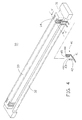
- FIG. 1 is an exploded view of an electrical connector assembly in accordance with a preferred embodiment of the present invention.
- FIG. 2 is an exploded view of a male connector of the electrical connector assembly of FIG. 1 .
- FIG. 3 is a cross-sectional view taken along line III—III in FIG. 2 .
- FIG. 4 is an exploded view of a female connector of the electrical connector assembly of FIG. 1 .
- FIG. 5 is a cross-sectional view taken along line V—V in FIG. 4 .
- FIG. 6 is a cross-section al view showing electrical connection of a male contact and a female contact when the male connector and the female connector are mated.
- an electrical connector assembly 1 in accordance with a preferred embodiment of the present invention includes a male connector 10 and a female connector 30 mating with the male connector 10 .
- the male connector 10 includes an elongate first insulative housing 12 and a plurality of male contacts 20 defined therein.
- the first housing 12 has a pair of side walls 14 , a pair of end walls 18 , and a central recess 15 surrounded by the side walls 14 and end walls 18 .
- a plurality of first receiving slots 16 is defined in the bottom wall of the housing 12 and extends through the bottom wall.
- Each male contact 20 comprises a mating portion 22 received in the first receiving slot 16 and a tail portion 24 extending vertically out of the bottom wall of the housing 12 .
- the mating portion 22 has a mating end 26 bent vertically and outwardly at one end thereof for attaching on a top surface of the side wall 14 .
- the mating end 26 has a first sloping contacting surface 28 and has a given width “A” for purposes described hereinafter.
- the female connector 30 includes an elongate second insulative housing 31 and a plurality of female contacts 40 defined therein.
- the housing 31 has two spaced side walls 32 and a central island 33 defined between the side walls 32 .
- the central island 33 defines a plurality of second receiving passageways 34 in opposite longitudinal sides thereof for receiving the female contacts 40 .
- Each female contact 40 has a base portion 41 defined horizontally under the bottom wall of the housing 31 .
- a first contacting portion 44 extends upwardly from one inner end of the base portion 41 in a vertical direction, the first contacting portion 44 is received in the second receiving slot 34 with a bending end 45 partly extending out of the second receiving passageway 34 .
- a second contacting portion 42 extends upwardly near an outer end of the base portion 41 in a direction substantially parallel with the first contacting portion 44 .
- the second contacting portion 42 is located immediately outside the side wall 32 and extends beyond a top surface of the side wall 32 .
- the second contacting portion 42 further defines a second sloping contacting surface 43 at a tip thereof for easily mating with the first sloping contacting surface 28 of the mating end 26 of the male contact 20 .
- the space 46 between the tip of the bending end 45 and an inner side of the second contacting portion 42 has a given width “B” that is slightly narrower than the width “A” of the mating end 26 of the male contact 20 .
- each male contact 20 mates with corresponding female contact 40 with the mating end 26 of the male contact 20 inserted into the space 46 and respectively establishing electrical connection with the first and second contacting portions 44 , 42 of the female contacting 40 .
- the mating end 26 of the male contact 20 firstly contacts the second contacting portion 42 of the female contact 40 with the second sloping surface 43 leading the male contact 20 along the first sloping surface 28 into the space 46 .
- the bending end 45 deforms outwardly such that the space B gets larger under the normal force initiated from the mating end 26 so as to receive the mating end 26 therein.
- the mating end 26 of the male contact 20 firstly contacts and oppresses the bending end 45 of the first contacting portion 44 of the female contact 40 such that the bending end 45 deforms outwardly to broaden the space “B”.
- the mating end 26 can also insert into the space “B” and establish electrical connection with the first and second contacting portion 44 , 42 , simultaneously.
Landscapes
- Coupling Device And Connection With Printed Circuit (AREA)
- Details Of Connecting Devices For Male And Female Coupling (AREA)
Abstract
An electrical connector assembly (1) comprises a male connector (10) and a female connector (30). The male connector has an elongate first insulative housing (12) and a plurality of male contacts (20) and the female connector has an elongate second insulative housing (31) and a plurality of female contacts (40). Each male contact has a mating portion (22) that can simultaneously contact a first and a second mating portions (44), (42) of the female contact such that a steady and liable electrical connection therebetween is established.
Description
1. Field of the Invention
The present invention relates to the art of electrical connectors, more particularly to electrical contacts of electrical connector assemblies for improving the performance of electrical connection therebetween.
2. Description of the Related Art
A connector assembly generally includes a male and a female connector mounted respectively on two spaced PC boards and adapted to mate with each other for mechanical and electrical interconnection therebetween. Each male and female connector commonly includes a miniature and elongate insulative housing that is manufactured by injection molding. The housing of the male connector is apt to deform in a lateral direction as a result of the remnant stress acting thereon. However, the level of deformation at both ends of the housing is different with the level of deformation at a middle portion of the housing. Therefore, side walls of the housing are inclined not to be planar. In such case, electrical contacts defined in the housing correspondingly offset from its correct positions such that the normal force between certain male contacts of the male connector and the female contacts of the female connector may become insufficient when the male connector and the female connector are mated. As a result, a reliable electrical connection between the male connector and the female connector cannot be assured.
Therefore, an object of the invention is to provide an electrical connector assembly wherein male contacts of a male connector can establish a stable contact with corresponding female contacts of a female connector for preventing an unstable electrical connection therebetween.
According to an aspect of the invention, an electrical connector assembly in accordance with the present invention comprises a male connector and a female connector. The male connector has an elongate first insulative housing and a plurality of male contacts defined therein. Each male contact has a mating portion retained in the first housing and a tail portion bent vertically from the mating portion and extending out from the first housing. Each female connector has an elongate second insulative housing and a plurality of female contacts defined therein. Each female contact has a base portion extending outside of the second housing, and a first and second mating portions bent vertically and extending upwardly from the base portion, respectively. The first and second mating portions are approximately parallel with each other and define a space therebetween for receiving the mating portion of the male contact therein. Thus, the mating portion of the male contact contacts with both the first and the second mating portions of the female contact such that a stable and liable electrical connection therebetween is established.
Other objects, advantages and novel features of the present invention will be drawn from the following detailed description of a preferred embodiment of the present invention with attached drawings, in which:
FIG. 1 is an exploded view of an electrical connector assembly in accordance with a preferred embodiment of the present invention.
FIG. 2 is an exploded view of a male connector of the electrical connector assembly of FIG. 1.
FIG. 3 is a cross-sectional view taken along line III—III in FIG. 2.
FIG. 4 is an exploded view of a female connector of the electrical connector assembly of FIG. 1.
FIG. 5 is a cross-sectional view taken along line V—V in FIG. 4.
FIG. 6 is a cross-section al view showing electrical connection of a male contact and a female contact when the male connector and the female connector are mated.
Referring to FIG. 1, an electrical connector assembly 1 in accordance with a preferred embodiment of the present invention includes a male connector 10 and a female connector 30 mating with the male connector 10.
Referring particularly to FIGS. 2 and 3, the male connector 10 includes an elongate first insulative housing 12 and a plurality of male contacts 20 defined therein. The first housing 12 has a pair of side walls 14, a pair of end walls 18, and a central recess 15 surrounded by the side walls 14 and end walls 18. A plurality of first receiving slots 16 is defined in the bottom wall of the housing 12 and extends through the bottom wall. Each male contact 20 comprises a mating portion 22 received in the first receiving slot 16 and a tail portion 24 extending vertically out of the bottom wall of the housing 12. The mating portion 22 has a mating end 26 bent vertically and outwardly at one end thereof for attaching on a top surface of the side wall 14. The mating end 26 has a first sloping contacting surface 28 and has a given width “A” for purposes described hereinafter.
Referring particularly to FIGS. 4 and 5, the female connector 30 includes an elongate second insulative housing 31 and a plurality of female contacts 40 defined therein. The housing 31 has two spaced side walls 32 and a central island 33 defined between the side walls 32. The central island 33 defines a plurality of second receiving passageways 34 in opposite longitudinal sides thereof for receiving the female contacts 40. Each female contact 40 has a base portion 41 defined horizontally under the bottom wall of the housing 31. A first contacting portion 44 extends upwardly from one inner end of the base portion 41 in a vertical direction, the first contacting portion 44 is received in the second receiving slot 34 with a bending end 45 partly extending out of the second receiving passageway 34. A second contacting portion 42 extends upwardly near an outer end of the base portion 41 in a direction substantially parallel with the first contacting portion 44. The second contacting portion 42 is located immediately outside the side wall 32 and extends beyond a top surface of the side wall 32. The second contacting portion 42 further defines a second sloping contacting surface 43 at a tip thereof for easily mating with the first sloping contacting surface 28 of the mating end 26 of the male contact 20. Referring to FIG. 5, the space 46 between the tip of the bending end 45 and an inner side of the second contacting portion 42 has a given width “B” that is slightly narrower than the width “A” of the mating end 26 of the male contact 20.
Referring to FIG. 6, in assembling, the central recess 14 of the first housing 12 of the male connector 10 receives the central island 33 of the second housing 31 of the female connector 30. Simultaneously, each male contact 20 mates with corresponding female contact 40 with the mating end 26 of the male contact 20 inserted into the space 46 and respectively establishing electrical connection with the first and second contacting portions 44, 42 of the female contacting 40. With that understood, if a protruding deformation along the first housing 12 of the male connector 10 occurs, the mating end 26 of the male contact 20 firstly contacts the second contacting portion 42 of the female contact 40 with the second sloping surface 43 leading the male contact 20 along the first sloping surface 28 into the space 46. At the same time, the bending end 45 deforms outwardly such that the space B gets larger under the normal force initiated from the mating end 26 so as to receive the mating end 26 therein. On the other hand, if the first housing 12 of the male connector 10 presents a concave deformation, the mating end 26 of the male contact 20 firstly contacts and oppresses the bending end 45 of the first contacting portion 44 of the female contact 40 such that the bending end 45 deforms outwardly to broaden the space “B”. Thus, the mating end 26 can also insert into the space “B” and establish electrical connection with the first and second contacting portion 44, 42, simultaneously.
It is to be understood, however, that even though numerous characteristics and advantages of the present invention have been set forth in the foregoing description, together with details of the structure and function of the invention, the disclosure is illustrative only, and changes may be made in detail, especially in matters of shape, size, and arrangement of parts within the principles of the invention to the full extent indicated by the broad general meaning of the terms in which the appended claims are expressed.
Claims (7)
1. An electrical connector assembly, comprising:
a male connector comprising an elongate first insualtive housing and a plurality of male contacts defined therein, each male contact having a mating portion;
a female connector comprising an elongate second insulative housing and a plurality of female contacts defined therein, each female contact having a base portion, a first and a second contacting portions spaced from each other and extending upwardly from the base portion in a substantially parallel manner such that a given space is defined therebetween; and
the mating portion of the male contact being inserted into the space and establish electrical connection with both the first and the second contacting portions of the female contact; wherein
a vertically bending end is formed in one end of the mating portion of the male contact.
2. The electrical connector assembly as claimed in claim 1 , wherein a width of the bending end is slightly larger than a width of the space.
3. The electrical connector assembly as claimed in claim 1 , wherein the second insulative housing of the female connector has a pair of spaced side walls and a central island defined between the side walls.
4. The electrical connector assembly as claimed in claim 3 , wherein the first contacting portion is received in the central island, and the second contacting portion is located outside the side wall and extends beyond the tip surface of the side wall.
5. An electrical connector assembly comprising:
a first connector defining a first housing with a pair of first sidewalls thereof;
a plurality of first contacts disposed on inner faces of said pair of first sidewalls;
a second connector defining a second housing with a pair of second sidewalls with a central island between;
a plurality of second contacts disposed by two sides of said central island; each of said first contacts including a mating portion being inside of the corresponding sidewall, and a mating end being outside of the corresponding first sidewall; and
each of said second contacts including a first contacting portion being inside of the corresponding second sidewall, and a second contacting portion being outside of the second corresponding sidewall; wherein
for each mated first contact and second contact, the mating portion engages the corresponding first contacting portion and the mating end engages the corresponding second contacting portion.
6. An electrical connector assembly comprising:
a first connector defining a first housing with at least one first sidewall thereof;
a plurality of first contacts with respectively stiff mating portions disposed on an inner face of said first sidewall and stiff mating ends exposed outside of the said first sidewall;
a second connector defining a second housing with at least a second sidewall;
a plurality of second contacts with inner resilient contacting portions and outer stiff contacting portions respectively disposed by two sides of said second sidewall; and
the mating portions with the associated first sidewall being sandwiched between the corresponding inner resilient contact portions and outer stiff contacting portions, respectively; wherein
the mating portions are mechanically and electrically engaged respectively with the corresponding inner resilient contacting portions, and the mating ends are mechanically and electrically engaged respectively with the corresponding outer stiff contacting portions.
7. An electrical connector assembly, comprising:
a male connector comprising an elongate first insualtive housing and a plurality of male contacts defined therein, each male contact having a mating portion;
a female connector comprising an elongate second insulative housing and a plurality of female contacts defined therein, each female contact having a base portion, a first and a second contacting portions spaced from each other and extending upwardly from the base portion in a substantially parallel manner such that a given space is defined therebetween; and
the mating portion of the male contact being inserted into the space and establish electrical connection with both the first and the second contacting portions of the female contact; wherein
the second insulative housing of the female connector has a pair of spaced side walls and a central island defined between the side walls; wherein
the first contacting portion is received in the central island, and the second contacting portion is located outside the side wall and extends beyond the tip surface of the side wall.
Priority Applications (1)
| Application Number | Priority Date | Filing Date | Title |
|---|---|---|---|
| US09/997,526 US6485312B1 (en) | 2001-11-29 | 2001-11-29 | Electrical connector assembly |
Applications Claiming Priority (1)
| Application Number | Priority Date | Filing Date | Title |
|---|---|---|---|
| US09/997,526 US6485312B1 (en) | 2001-11-29 | 2001-11-29 | Electrical connector assembly |
Publications (1)
| Publication Number | Publication Date |
|---|---|
| US6485312B1 true US6485312B1 (en) | 2002-11-26 |
Family
ID=25544129
Family Applications (1)
| Application Number | Title | Priority Date | Filing Date |
|---|---|---|---|
| US09/997,526 Expired - Fee Related US6485312B1 (en) | 2001-11-29 | 2001-11-29 | Electrical connector assembly |
Country Status (1)
| Country | Link |
|---|---|
| US (1) | US6485312B1 (en) |
Cited By (5)
| Publication number | Priority date | Publication date | Assignee | Title |
|---|---|---|---|---|
| US20040142586A1 (en) * | 2003-01-22 | 2004-07-22 | Hung-Chi Yu | Electrical connector assembly with locking means |
| US20040185691A1 (en) * | 2003-03-21 | 2004-09-23 | Hao-Yun Ma | Board-to-board electrical connector assembly |
| US20050042898A1 (en) * | 2003-09-06 | 2005-02-24 | Chi Zhang | Electrical connector assembly |
| EP1617518A1 (en) * | 2004-06-15 | 2006-01-18 | Funkwerk Dabendorf GmbH | Connector |
| US9525224B1 (en) * | 2015-08-03 | 2016-12-20 | Hon Hai Precision Industry Co., Ltd. | Electrical connector and electronic system |
Citations (5)
| Publication number | Priority date | Publication date | Assignee | Title |
|---|---|---|---|---|
| US5199884A (en) * | 1991-12-02 | 1993-04-06 | Amp Incorporated | Blind mating miniature connector |
| US5478248A (en) * | 1993-12-17 | 1995-12-26 | Berg Technology, Inc. | Connector for high density electronic assemblies |
| US5626500A (en) * | 1994-05-30 | 1997-05-06 | The Whitaker Corporation | Contact and connector |
| US5915976A (en) * | 1997-02-06 | 1999-06-29 | Hon Hai Precision Ind. Co., Ltd. | High speed connector |
| US6159021A (en) * | 1995-02-09 | 2000-12-12 | The Whitaker Corporation | Electrical connector for printed circuit boards |
-
2001
- 2001-11-29 US US09/997,526 patent/US6485312B1/en not_active Expired - Fee Related
Patent Citations (5)
| Publication number | Priority date | Publication date | Assignee | Title |
|---|---|---|---|---|
| US5199884A (en) * | 1991-12-02 | 1993-04-06 | Amp Incorporated | Blind mating miniature connector |
| US5478248A (en) * | 1993-12-17 | 1995-12-26 | Berg Technology, Inc. | Connector for high density electronic assemblies |
| US5626500A (en) * | 1994-05-30 | 1997-05-06 | The Whitaker Corporation | Contact and connector |
| US6159021A (en) * | 1995-02-09 | 2000-12-12 | The Whitaker Corporation | Electrical connector for printed circuit boards |
| US5915976A (en) * | 1997-02-06 | 1999-06-29 | Hon Hai Precision Ind. Co., Ltd. | High speed connector |
Cited By (8)
| Publication number | Priority date | Publication date | Assignee | Title |
|---|---|---|---|---|
| US20040142586A1 (en) * | 2003-01-22 | 2004-07-22 | Hung-Chi Yu | Electrical connector assembly with locking means |
| US6846187B2 (en) * | 2003-01-22 | 2005-01-25 | Hon Hai Precision Ind. Co., Ltd | Electrical connector assembly with locking means |
| US20040185691A1 (en) * | 2003-03-21 | 2004-09-23 | Hao-Yun Ma | Board-to-board electrical connector assembly |
| US6926538B2 (en) * | 2003-03-21 | 2005-08-09 | Hon Hai Precision Ind. Co., Ltd. | Board-to-board electrical connector assembly |
| US20050042898A1 (en) * | 2003-09-06 | 2005-02-24 | Chi Zhang | Electrical connector assembly |
| US6905345B2 (en) | 2003-09-06 | 2005-06-14 | Hon Hai Precision Ind. Co., Ltd | Electrical connector assembly |
| EP1617518A1 (en) * | 2004-06-15 | 2006-01-18 | Funkwerk Dabendorf GmbH | Connector |
| US9525224B1 (en) * | 2015-08-03 | 2016-12-20 | Hon Hai Precision Industry Co., Ltd. | Electrical connector and electronic system |
Similar Documents
| Publication | Publication Date | Title |
|---|---|---|
| US6585537B1 (en) | Cable end connector with locking member | |
| US6183287B1 (en) | Electrical connector | |
| US8961235B2 (en) | Electrical connector with improved mating member having anti-mismating portion for preventing incorrect insertion | |
| US7371125B2 (en) | Miniature audio jack connector | |
| US6690801B2 (en) | Audio jack having improved arrangement of contacts | |
| US6575793B1 (en) | Audio jack connector | |
| US20050112952A1 (en) | Power jack connector | |
| US7470153B2 (en) | Audio jack with improved contact arrangement | |
| US20050227524A1 (en) | Modular jack with a detective switch | |
| US20070066141A1 (en) | Electrical connector having an inner printed circuit board | |
| US8529298B2 (en) | Electronic card connector with a releasing portion for inserting or ejecting an electronic card smoothly | |
| US6485315B1 (en) | Electrical plug connector with spring latch and grounding tabs | |
| US20090149042A1 (en) | Electrical connector having flexibly and steadily enagagement between metallic shells and grounding terminals | |
| US20020064996A1 (en) | Retention element for electrical connector | |
| US6863559B2 (en) | Electrical connector for flexible printed circuit | |
| US20090186497A1 (en) | Electrical connector having power terminals | |
| US6077092A (en) | Electrical connector having stabilizing structure for spacer and terminal | |
| US6918799B2 (en) | Electrical connector having contact with pre-pressing structure | |
| US20060052008A1 (en) | Electrical connector with guidance face | |
| US6890220B2 (en) | Electrical connector assembly | |
| US6458001B1 (en) | Receptacle connector having anti-mismating structures | |
| US6971923B1 (en) | Cable end connector assembly with improved organizer | |
| US6485312B1 (en) | Electrical connector assembly | |
| US6508677B1 (en) | Low profile modular jack | |
| US6905345B2 (en) | Electrical connector assembly |
Legal Events
| Date | Code | Title | Description |
|---|---|---|---|
| AS | Assignment |
Owner name: HON HAI PRECISION IND. CO., LTD., TAIWAN Free format text: ASSIGNMENT OF ASSIGNORS INTEREST;ASSIGNOR:YU, HUNG-CHI;REEL/FRAME:012341/0378 Effective date: 20011113 |
|
| FPAY | Fee payment |
Year of fee payment: 4 |
|
| REMI | Maintenance fee reminder mailed | ||
| LAPS | Lapse for failure to pay maintenance fees | ||
| STCH | Information on status: patent discontinuation |
Free format text: PATENT EXPIRED DUE TO NONPAYMENT OF MAINTENANCE FEES UNDER 37 CFR 1.362 |
|
| FP | Lapsed due to failure to pay maintenance fee |
Effective date: 20101126 |