US6414823B1 - Coil-structures for magnetic microactuator - Google Patents
Coil-structures for magnetic microactuator Download PDFInfo
- Publication number
- US6414823B1 US6414823B1 US09/490,421 US49042100A US6414823B1 US 6414823 B1 US6414823 B1 US 6414823B1 US 49042100 A US49042100 A US 49042100A US 6414823 B1 US6414823 B1 US 6414823B1
- Authority
- US
- United States
- Prior art keywords
- microactuator
- coil
- disc
- magnets
- disc drive
- Prior art date
- Legal status (The legal status is an assumption and is not a legal conclusion. Google has not performed a legal analysis and makes no representation as to the accuracy of the status listed.)
- Expired - Lifetime
Links
Images


Classifications
-
- G—PHYSICS
- G11—INFORMATION STORAGE
- G11B—INFORMATION STORAGE BASED ON RELATIVE MOVEMENT BETWEEN RECORD CARRIER AND TRANSDUCER
- G11B5/00—Recording by magnetisation or demagnetisation of a record carrier; Reproducing by magnetic means; Record carriers therefor
- G11B5/48—Disposition or mounting of heads or head supports relative to record carriers ; arrangements of heads, e.g. for scanning the record carrier to increase the relative speed
- G11B5/54—Disposition or mounting of heads or head supports relative to record carriers ; arrangements of heads, e.g. for scanning the record carrier to increase the relative speed with provision for moving the head into or out of its operative position or across tracks
- G11B5/55—Track change, selection or acquisition by displacement of the head
- G11B5/5521—Track change, selection or acquisition by displacement of the head across disk tracks
- G11B5/5552—Track change, selection or acquisition by displacement of the head across disk tracks using fine positioning means for track acquisition separate from the coarse (e.g. track changing) positioning means
-
- G—PHYSICS
- G11—INFORMATION STORAGE
- G11B—INFORMATION STORAGE BASED ON RELATIVE MOVEMENT BETWEEN RECORD CARRIER AND TRANSDUCER
- G11B21/00—Head arrangements not specific to the method of recording or reproducing
- G11B21/16—Supporting the heads; Supporting the sockets for plug-in heads
- G11B21/18—Supporting the heads; Supporting the sockets for plug-in heads while the head is moving
Definitions
- the present invention relates to a disc drive microactuator, and more particularly to improved coil structures for use in a magnetic microactuator utilizing a vertical magnetic circuit contained on a substrate and a flex circuit to provide microactuation force.
- head positioning is accomplished by operating an actuator arm with a large-scale actuation motor, such as a voice coil motor, to radially position a head on a flexure at the end of the actuator arm.
- a large-scale actuation motor such as a voice coil motor
- the large scale motor lacks sufficient resolution to effectively accommodate high track-density discs.
- a high resolution head positioning mechanism, or microactuator is necessary to accommodate the more densely spaced tracks.
- One promising approach for high resolution head positioning involves employing a high resolution microactuator in addition to the conventional lower resolution actuator motor, thereby effecting head positioning through dual-stage actuation.
- Various microactuator designs have been considered to accomplish high resolution head positioning.
- One design involves inserting a silicon-based thin film structure between the suspension and the slider in a disc drive assembly.
- a major technical challenge in implementing such a microactuator is to provide sufficiently large actuation force to overcome spring bias forces to drive the head at a speed high enough to accommodate the required bandwidth.
- Such a design must be realized in a relatively small wafer area, to keep costs reasonable and to allow easy integration into the disc drive design.
- the present invention is a microactuator for a disc drive includes a stator attached to the disc drive support structure, a rotor operatively attached to a slider, the rotor being movable with respect to the stator in a first horizontal plane generally parallel to the surface of the disc, and a vertically arranged magnetic circuit.
- the magnetic circuit is arranged in a plurality of planes substantially parallel to the first horizontal plane so as to move the microactuator rotor and the slider in the first horizontal plane with a stroke of at least about 2 micro-meters in response to a current of no greater than about 100 milli-Amps provided to the magnetic circuit.
- FIG. 1 is a perspective view of a disc drive actuation system for positioning a slider over tracks of a disc.
- FIG. 2 is an exploded perspective view of a portion of a disc drive including a microactuator according to the present invention.
- FIG. 3 is a perspective view of a microactuator system for positioning a slider over tracks of a disc.
- FIG. 4 is a top view of the microactuator system shown in FIG. 3 .
- FIG. 5 is a perspective view of the underside of a flex circuit for use with a magnetic microactuator according to a first embodiment of the present invention.
- FIG. 6 is a perspective view of the magnetic microactuator attached to the flex circuit according to the first embodiment of the present invention.
- FIG. 7A is a top perspective view of a magnetic microactuator system having a top keeper plate carrying a dual-layer coil according to a second embodiment of the present invention.
- FIG. 7B is a bottom perspective view of the magnetic microactuator system shown in FIG. 7 A.
- FIG. 7C is a perspective view of the magnetic microactuator system shown in FIGS. 7A and 7B showing connections to a load beam and gimbal for implementing the system in a disc drive.
- FIG. 8 is a perspective view of the underside of the top keeper plate according to the second embodiment of the present invention.
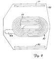
- FIG. 9 is a bottom view of the top keeper plate illustrating a first coil layer according to the second embodiment of the present invention.
- FIG. 10 is a bottom view of the top keeper plate illustrating a second coil layer according to the second embodiment of the present invention.
- FIG. 11 is a bottom view of the top keeper plate according to the second embodiment of the present invention, having separate coil terminals formed thereon for electrically contacting a flex circuit.
- FIG. 12 is a top perspective view of a magnetic microactuator system with a top keeper plate carrying a dual-layer coil and having upwardly facing separate coil terminals according to an alternate arrangement of the second embodiment of the present invention.
- FIG. 13 is atop perspective view of a magnetic microactuator system having a top keeper plate as generally shown in FIG. 12, further illustrating the flex circuit for contacting the microactuator and the transducing head.
- FIG. 14 is a section view of a disc drive system employing the magnetic microactuator system of the second embodiment of the present invention.
- FIG. 15 is a perspective view of a magnetic microactuator suspension for carrying a moving dual-layer coil according to a third embodiment of the present invention.
- FIG. 16 is a top view of the microactuator suspension shown in FIG. 11 illustrating the first coil layer.
- FIG. 17 is a top view of the microactuator suspension shown in FIG. 11 illustrating the second coil layer.
- FIG. 18 is a perspective view of the microactuator suspension shown in FIG. 11 having an attached flex circuit carrying the magnets and top keeper according to the third embodiment of the present invention.
- FIG. 19A is a section view of a disc drive system employing a magnetic microactuator system according to the third embodiment of the present invention, with microactuator contacts on the microactuator suspension at a distal end near the slider.
- FIG. 19B is a section view of a disc drive system employing a magnetic microactuator system according to the third embodiment of the present invention, with microactuator contacts on the microactuator suspension at a proximal end opposite from the slider.
- FIG. 20 is a plan view of a single-layer coil for use with a magnetic microactuator employing four magnets, according to a fourth embodiment of the present invention.
- FIG. 21 is a plan view of a single-layer coil for use with a magnetic microactuator employing two magnets, according to the fourth embodiment of the present invention.
- FIG. 1 is a perspective view of a disc drive actuation system 10 for positioning slider 24 over a track 29 of disc 27 .
- Actuation system 10 includes voice coil motor (VCM) 12 arranged to rotate actuator arm 16 on a spindle around axis 14 .
- Head suspension 18 is connected to actuator arm 16 at head mounting block 20 .
- Flexure 22 is connected to an end of head suspension 18 , and carries slider 24 .
- Slider 24 carries a transducing head (not shown in FIG. 1) for reading and/or writing data on concentric tracks 29 of disc 27 .
- Disc 27 rotates around axis 28 , so that windage is encountered by slider 24 to keep it aloft a small distance above the surface of disc 27 .
- VCM 12 is selectively operated to move actuator arm 16 around axis 14 , thereby moving slider 24 between tracks 29 of disc 27 .
- VCM 12 lacks sufficient resolution and frequency response to position a transducing head on slider 24 precisely over a selected track of disc 27 . Therefore, a higher resolution actuation device is necessary.
- FIG. 2 is an exploded perspective view of a portion of a disc drive including microactuator 30 for high resolution head positioning.
- Flexure 22 is attached to load beam 18
- microactuator 30 is attached to flexure 22 to carry slider 24 above a surface of disc 27 (FIG. 1 ).
- Transducing head 26 is carried by slider 24 to transduce data with the disc.
- load beam 18 , flexure 22 and microactuator 30 carrying slider 24 are all moved together as coarse positioning is performed by VCM 12 (FIG. 1) moving actuator arm 16 (FIG. 1 ).
- microactuator 30 generates a force which causes bending of the beam springs of the microactuator.
- the portion of microactuator 30 carrying slider 24 moves slightly with respect to flexure 22 in the direction of arrows 31 , displacing transducing head 26 with high resolution for precise positioning over a selected track of the disc.
- FIG. 3 is a perspective view
- FIG. 4 is a top view, of microactuator 30 for use in a disc drive system.
- Microactuator 30 includes outer preloading bars 32 and 34 and inner alignment clips 36 and 38 , with inner alignment clips 36 and 38 clamping against the sides of slider 24 at a frontal portion (to the right in FIGS. 3 and 4) thereof.
- Flexible beam springs 33 and 35 extend between the proximal ends of preloading bars 32 and 34 and the distal ends of alignment clips 36 and 38 .
- Tub 40 having a bottom surface lined with a ferromagnetic keeper material is formed in the substrate of microactuator 30 opposite transducing head 26 of slider 24 , and structural bond pad 42 is provided for attachment to the top surface (opposite the air-bearing surface) of slider 24 .
- Magnets 52 and 53 are located in tub 40 , attached to the ferromagnetic lining on the bottom surface of tub 40 .
- Standoffs 54 , 56 , 58 and 60 are formed on respective standoff bases 44 , 46 , 48 and 50 on outer preloading bars 32 and 34 , to be borne upon so as to apply pre-load force to microactuator 30 as it supports slider 24 over the surface of the disc.
- microactuator 30 has an outer perimeter of about 2195 by 1600 by 200 microns.
- the detail of the construction and operation of microactuator 30 are disclosed in U.S. application Ser. No. 09/315,006, which has been incorporated herein by reference.
- FIG. 5 is a perspective view of the underside of flexure 22 having flex circuit patterns formed thereon for use with a magnetic microactuator according to a first embodiment of the present invention.
- Flexure 22 is formed of a non-conductive polyimide material such as Kapton, for example, and forms the substrate of a flex circuit including conductive coil first layer 62 a connected to current-providing source 63 , and standoffs 64 , 66 , 68 and 70 .
- Standoffs 64 , 66 , 68 and 70 are aligned with respective standoffs 54 , 56 , 58 and 60 of microactuator 30 to apply pre-load force to microactuator 30 as it carries slider 24 (FIG. 3 ).
- conductive leads 72 , 74 , 76 and 78 are provided to electrically contact transducing head 26 carried by slider 24 (FIG. 3 ).
- Coil 62 and data leads 72 , 74 , 76 and 78 are formed of a conductive material such as copper.
- Standoffs 64 , 66 , 68 and 70 are preferably formed of copper, or alternatively of a material such as nickel. In some embodiments, standoffs 64 , 66 , 68 and 70 may be formed with sufficient thickness so as to render standoffs 54 , 56 , 58 and 60 on microactuator 30 (FIG. 3) unnecessary.
- the total standoff height between magnets 52 and 53 and coil 62 is typically about 10 to 100 micro-meters ( ⁇ m), with an exemplary height of 50 ⁇ m in one embodiment.
- Flexure 22 is typically about 50 ⁇ m thick, and may be made as thin as about 25 ⁇ m with some trade-off in durability.
- coil first layer 62 a is about 15 ⁇ m thick.
- FIG. 6 is a perspective view of microactuator 30 of the present invention attached to the underside of flexure 22 for use in a disc drive.
- Flexure 22 includes conductive coil second layer 62 b and ferromagnetic keeper 82 formed on its top surface opposite coil first layer 62 a (FIG. 5) above magnets 52 and 53 located in tub 40 of microactuator 30 (FIG. 3 ).
- a vertically arranged magnetic circuit is thereby formed from the bottom keeper (ferromagnetic lining of tub 40 ), magnets 52 and 53 , an airgap formed by the spacing between magnets 52 and 53 and dual-layer coil 62 , the windings of coil layers 62 a and 62 b themselves, flexure 22 and top keeper 82 .
- Keeper 82 may be plated on the polyimide substrate of flexure 22 (with an insulating layer for isolating keeper 82 from coil second layer 62 b ) or adhesively bonded thereto.
- Flexure 22 is shaped to include arms 84 and 86 and cross beams 88 and 90 for supporting data leads 72 , 74 , 76 and 78 , and central portion 92 for supporting coil 62 and standoffs 64 , 66 , 68 and 70 .
- Pre-load force is applied in a preferred embodiment to central portion 92 of flexure 22 by load beam 18 (FIG. 2 ).
- the arrangement of flexure 22 and the design of microactuator 30 are such that operation of microactuator 30 by circulating current through the windings of dual-layer coil 62 results in cross-track movement of slider 24 in a horizontal plane generally parallel to the surface of the disc, in the direction of arrows 31 , with the movement being permitted by the flexibility of beam springs 33 and 35 (FIG.
- Outer preloading bars 32 and 34 having standoffs 54 , 56 , 58 and 60 thereon effectively form the stator of the motor, with magnets 52 and 53 , slider bond pad 42 , slider 24 , flexible beams 33 and 35 and inner alignment clips 36 and 38 effectively forming the rotor of the motor (FIG. 3 ).
- lateral movement of magnets 52 and 53 affects the cross-track (radial) position of slider 24 with respect to outer preloading bars 32 and 34 and standoffs 54 , 56 , 58 and 60 , and also with respect to flexure 22 and to the tracks of the disc, thereby achieving high resolution positioning of the transducing head.
- Conductive coil first layer 62 a and second layer 62 b are formed on opposite sides of the polyimide substrate of flexure 22 , with a conductive via connecting the layers through the substrate at vertically adjacent portions 65 a and 65 b .
- the conductive via extends through a 75 ⁇ m diameter hole laser drilled in the flexure substrate.
- the wire width and spacing of coil first layer 62 a and second layer 62 b is presently constrained to a minimum of about 38 ⁇ m due to limitations of flexure processing; smaller wire widths and spacings are contemplated by the present invention as the resolution of flexure processing improves.
- coil 62 With the wire width and spacing at 38 ⁇ m, 20 traverses of the face of magnets 52 and 53 are made, with coil 62 having a length of 559 ⁇ m. With the exemplary dimensions given above, coil 62 has a resistance of 1.54 Ohms at an operating temperature of 150° C. A current of 100 milli-Amperes (mA) provided by current providing source 63 through coil 62 results in an actuation force of 0.67 milli-Newtons (mN), achieved with power dissipation of 15 milli-Watts (mW). For a design implementing microactuator 30 as shown in FIGS. 3 and 4 and having a typical offtrack resonance of 1000 Hz, a microactuation stroke of 6.4 ⁇ m in each direction is achieved.
- mN milli-Newtons
- a microactuator stroke of 1 to 2 ⁇ m is required for tracking operations (centering the head over a selected track), while a microactuator stroke of greater than 2 ⁇ m is required for seeking operations (moving the head between tracks).
- the embodiment shown in FIGS. 5 and 6 is therefore a simple design that is able to provide a useful microactuator stroke with an actuation current of 100 mA or less, with low power dissipation.
- the fabrication processes of this embodiment are also relatively simple and inexpensive to perform.
- FIG. 7A is a top perspective view
- FIG. 7B is a bottom perspective view, of a magnetic microactuator system having top keeper plate 100 carrying a dual-layer coil according to a second embodiment of the present invention.
- Top keeper plate 100 is formed of a ferromagnetic material, carries a dual-layer coil on its underside surface, and is attached to microactuator 98 on standoffs 101 and 102 by a suitable bonding method known in the art.
- Microactuator 98 has a bottom ferromagnetic keeper and a pair of magnets formed thereon, and is constructed in a manner similar to magnetic microactuator 30 described above, thereby creating a vertical magnetic circuit that is able to horizontally move the magnets of the microactuator and effect displacement of transducing head 26 in the direction of arrows 31 .
- microactuator 98 has an outer perimeter of about 2195 by 1600 by 200 microns in an exemplary configuration.
- Flex circuit 103 is provided for electrical connections, with flex circuit portion 104 electrically connecting to transducing head 26 on slider 24 , and flex circuit portion 105 electrically connecting to the dual-layer coil carried by top keeper plate 100 , at bond pads 112 a and 112 b .
- the details of top keeper plate 100 are discussed below with respect to FIGS. 8-11.
- FIG. 7C is a perspective view of the magnetic microactuator system shown in FIGS. 7A and 7B, including load beam 18 and gimbal 106 arranged to implement the microactuator system in a disc drive.
- Load beam 18 includes an aperture 107 spanned by a central dimpled portion 108 for applying the necessary pre-loading force to maintain slider 24 in proximity with the surface of the disc.
- Gimbal 106 is attached between load beam 18 and top keeper 100 , and includes bridge portion 109 that is borne upon by dimpled portion 108 of load beam 18 to apply the pre-loading force through microactuator 30 to slider 24 .
- FIG. 8 is a perspective view of the underside of top keeper plate 100 according to the second embodiment of the present invention.
- Top keeper plate 100 includes standoffs 110 and 111 for vertically spacing top keeper plate 100 from microactuator 30 when it is bonded thereto on standoffs 101 and 102 (FIG. 7 A).
- Dual-layer coil 112 is formed on the underside of top keeper plate 100 from a conductive material such as copper, with a first layer of coil 112 terminating at first layer bond pad 112 a and a second layer of coil 112 terminating at second layer bond pad 112 b .
- Bond pads 112 a and 112 b are electrically connected to flex circuit portion 105 (FIGS.
- FIG. 9 is a bottom view of top keeper plate 100 showing the first layer of coil 112
- FIG. 10 is a bottom view of top keeper plate 100 showing the second layer of coil 112 .
- FIG. 11 is a bottom view of another configuration of top keeper plate 100 having separate coil terminal bond pads 112 a and 112 b formed thereon for electrically contacting flex circuit portion 105 (FIGS. 7 A and 7 B).
- Coil terminal bond pads 112 a and 112 b are electrically connected to the respective layers of dual-layer coil 112 , although these connections are not visible in FIG. 11 because of the presence of an insulating layer over the conductors between coil terminal bond pads 112 a and 112 b and dual-layer coil 112 .
- FIG. 12 is a perspective view of magnetic microactuator system 98 having top keeper plate 100 carrying a dual-layer coil and having upwardly facing separate coil terminal bond pads 112 a and 112 b for connecting the dual-layer coil to a flex circuit.
- Coil terminal bond pads 112 a and 112 b are electrically connected to the respective layers of the dual-layer coil carried on the underside of top keeper plate 100 .
- Top keeper plate 100 is positioned on standoffs 101 and 102 in a manner similar to that shown in FIG. 7A, vertically adjacent to the magnets and the bottom keeper carried by microactuator 98 .
- FIG. 13 is a perspective view of magnetic microactuator system 98 as shown in FIG. 12, further illustrating flex circuit 103 for electrically contacting the dual-layer coil carried by top keeper plate 100 and the transducing head carried by the disc drive slider.
- Flex circuit 103 includes flex circuit portion 104 for electrically contacting the transducing head, and flex circuit portion 105 for connection to coil terminal bond pads 112 a and 112 b to supply current through the dual-layer coil carried by top keeper plate 100 , and coil via terminal 113 is provided to connect to the center of coil 112 for an alternate embodiment where a single-layer coil is used on top keeper plate 100 rather than a dual-layer coil.
- FIG. 14 is a section view taken at the center of the width of a disc drive system employing magnetic microactuator 98 according to the second embodiment of the present invention.
- the magnetic circuit formed below suspension load beam 18 includes top keeper plate 100 carrying dual-layer coil 112 , magnets 52 , 53 and bottom keeper 41 .
- Top keeper plate 100 includes an extended portion supporting separate coil terminal bond pads 112 a and 112 b connected to respective layers of dual-layer coil 112 .
- Flex circuit portion 105 is electrically connected to coil terminal bonds pads 112 a and 112 b to supply current through dual-layer coil 112 to operate microactuator 98 .
- Flex circuit portion 104 is electrically connected to the transducing head carried by slider 24 . In the configuration shown in FIG. 14, with a gap between flex circuit portion 105 and suspension load beam 18 of 50 micro-meters ( ⁇ m), the total package height from the top of suspension load beam 18 to the bottom of slider 24 is 735 ⁇ m.
- microactuator 98 is achieved by circulating current through the windings of dual-layer coil 112 which results in cross-track movement of slider 24 in a horizontal plane generally parallel to the surface of the disc, in the direction of arrows 31 , with the movement being permitted by the flexibility of the beam springs of microactuator 98 .
- Microactuator 98 is structurally similar to microactuator 30 shown in FIG. 3, with outer preloading bars forming the stator of the motor and magnets, a slider bond pad, slider 24 , flexible beams and inner alignment clips effectively forming the rotor of the motor (see FIG. 3 ).
- the second embodiment of the present invention may implement dual-layer coil 112 with a wire size and spacing of 8 ⁇ m and a wire thickness of 15 ⁇ m.
- This wire configuration provides 88 magnet face traverses, and coil 112 has a resistance of 25.4 Ohms at 150° C.
- this embodiment is able to achieve microactuation performance at low current levels that is significantly improved over prior art configurations, as shown in the table below.
- the microactuator of the second embodiment of the present invention is able to achieve microactuator strokes greater than 12 ⁇ m.
- a stroke of greater than about 12 ⁇ m is required to ensure proper microactuator seeking operation performance in a disc drive system having a disc stack of 10 discs, due to misalignment between the disc stack spindle and the actuator system.
- top keeper plate 100 is attached to microactuator 98 to form a unitary microactuator structure, that does not require any additional steps when the disc drive is being assembled.
- FIG. 15 is a perspective view of magnetic microactuator 114 for carrying a movable dual-layer coil (that is, as part of the microactuator rotor) according to a third embodiment of the present invention.
- Microactuator 114 includes outer preloading bars 115 and 116 and inner alignment clips 117 and 118 for receiving a slider (not shown) therebetween.
- Flexible beam springs 120 and 122 connect outer preloading bar 115 and inner alignment clip 117
- flexible beam springs 124 and 126 connect outer preloading bar 116 and inner alignment clip 118 .
- a ferromagnetic keeper 130 is provided on the substrate of microactuator 114 .
- Keeper 130 may take the form of an insert molded into a recess formed in the substrate, where the substrate is formed by a Metal Injection Molding (MIM) process.
- Standoffs 132 and 134 are provided on outer preloading bars 115 and 116 to be borne upon by a preloading bridge of a flexure (such as flexure 22 , FIG. 3) to apply preload force to the microactuator structure.
- MIM Metal Injection Molding
- Bond pads 136 , 138 and 140 are provided for attachment to a top surface (opposite the air-bearing surface) of a slider, so that movement of alignment clips 117 and 118 with respect to outer preloading bars 115 and 116 effected by microactuator 114 results in corresponding radial movement of the slider to achieve high resolution positioning of the transducing head carried by the slider.
- FIG. 16 is a top view of magnetic microactuator 114 illustrating a first coil layer of dual-layer coil 150 on ferromagnetic keeper 130
- FIG. 17 is a top view of magnetic microactuator 114 illustrating both coil layers of dual-layer coil 150 .
- the first layer of dual-layer coil 150 is connected by conductive trace 152 formed on inner alignment clip 117 to bond pad 154
- the second layer of dual-layer coil 150 is connected by conductive trace 153 formed on inner alignment clip 118 to bond pad 155
- the first and second layers of dual-layer coil are connected to each other by conductive via 156 .
- FIG. 18 is a perspective view of magnetic microactuator 114 having flexure 22 suspended thereabove to carry magnets 162 and 163 and top ferromagnetic keeper 164 and to provide preloading force to standoffs 132 and 134 on outer preloading bars 115 and 116 .
- Flexure 22 is shaped to include arms 84 and 86 and cross beam 89 therebetween at a distal end of flexure 22 .
- Central bridge portion 92 is located in the aperture between arms 84 and 86 and cross beam 89 , with a platform directly above dual-layer coil 150 , and bears upon standoffs 132 and 134 to apply preloading force to outer preloading bars 115 and 116 of microactuator 114 .
- Magnets 162 and 163 are attached to bridge portion 92 of flexure 22 above dual-layer coil 150 , and top ferromagnetic keeper 164 is formed on top of magnets 164 to complete the vertical magnetic circuit of bottom ferromagnetic keeper 130 , dual-layer coil 150 , magnets 162 and 163 and top ferromagnetic keeper 164 .
- top ferromagnetic keeper 164 is formed on top of magnets 164 to complete the vertical magnetic circuit of bottom ferromagnetic keeper 130 , dual-layer coil 150 , magnets 162 and 163 and top ferromagnetic keeper 164 .
- magnets 162 and 163 are fixed and dual-layer coil 150 on bottom ferromagnetic keeper 130 moves laterally in response to a current applied at bond pads 154 and 155 to flow through dual-layer coil 150 , thereby effecting movement of slider-supporting alignment clips 117 and 118 with respect to outer preloading bars 115 and 116 to radially position the transducing head carried by the slider.
- Dual-layer coil 150 may be formed in a manner similar to dual-layer coil 106 shown with respect to the second embodiment (FIGS. 7A, 7 B, 7 C and 8 - 14 ), with a wire size and spacing of 8 ⁇ m and a wire thickness of 15 ⁇ m. This wire configuration has characteristic parameters and performance similar to that described above with respect to the second embodiment of the invention. Dual-layer coil 150 may be plated, etched, wound from fine wire or realized by any other suitable method known in the art to achieve the desired resolution and magnet face traverses.
- FIG. 19A is a section view taken at the center of the width of a disc drive system employing magnetic microactuator 114 according to the third embodiment of the present invention.
- the magnetic circuit formed below suspension load beam 18 includes top keeper 164 , magnets 162 , 163 , dual-layer coil 150 and bottom keeper 130 .
- Flex circuit 166 is provided to make electrical connections with the transducing head carried by slider 24 and to coil 150 for operating microactuator 114 .
- Flex circuit portion 168 is electrically connected to coil terminal bonds pads 154 and 155 (shown in FIGS. 17 and 18) to supply current through conductive traces 152 and 153 (FIG. 17) to coil 150 for operation of microactuator 114 .
- Flex circuit portion 169 is electrically connected to the transducing head carried by slider 24 .
- FIG. 19B is a section view taken at the center of the width of a disc drive system employing magnetic microactuator 114 according to an alternate configuration of the third embodiment of the present invention.
- the magnetic circuit formed below suspension load beam 18 includes top keeper 164 , magnets 162 , 163 , dual-layer coil 150 and bottom keeper 130 .
- the substrate of microactuator 114 includes an extended portion supporting separate coil terminal bond pads 150 a and 150 b for electrical connection to the respective layers of dual-layer coil 150 .
- Flex circuit 166 is provided to make electrical connections with the transducing head carried by slider 24 and to coil 150 for operating microactuator 114 .
- Flex circuit portion 168 is electrically connected to coil terminal bonds pads 150 a and 150 b to supply current through coil 150 for operation of microactuator 114 .
- Flex circuit portion 169 is electrically connected to the transducing head carried by slider 24 .
- the substrate of microactuator 114 is slightly larger than microactuator 30 (FIG. 3) or microactuator 98 (FIG. 7 A), with an outer perimeter of about 3095 by 1900 by 200 microns in an exemplary configuration.
- FIGS. 19A and 19B enable reduction of the head gimbal assembly (HGA) package height by 70 ⁇ m relative to the second embodiment, to a total package height of 665 ⁇ m.
- HGA head gimbal assembly
- FIG. 20 is a plan view of single-layer coil 170 for use with a magnetic microactuator employing four magnets, according to a fourth embodiment of the present invention.
- the drawing of FIG. 20 is illustrative in nature, and does not necessarily depict the exact dimensional relationships and total number of coil windings and traverses that are actually utilized in the microactuator system.
- Single layer coil 170 is formed on the underside of a top keeper plate, similar to the configuration of the first coil layer of dual-layer coil 150 shown in FIG. 9 .
- bond pads 170 a and 170 b are provided to electrically contact coil 170 , for connection to a current-providing source.
- An out-of-plane jumper connection is required to access bond pad 170 a , which may be provided by the flex circuit or by a pattern of conductive traces on the top keeper plate itself.
- the conductor spacing may be made as small as 5 ⁇ m with a conductor width of 15 ⁇ m and a conductor thickness as great as 50 ⁇ m. Coil thicknesses up to about 50 ⁇ m are desirable to minimize the coil resistance and its associated power dissipation, while coil thicknesses exceeding about 50 ⁇ m tend to cause a decrease in magnetic field strength due to increased gap length in the magnetic circuit. With this configuration, nine coil traverses per magnet, or 36 total magnet face traverses, are achieved, and the coil resistance at 150° C. is 1.3 Ohms. For the amounts of microactuation force shown in the table above with respect to FIGS.
- 61 milli-Amps (mA) of current through the 72 turn single layer coil generates 1.48 milli-Newtons (mN) of force with a power dissipation of 29 milli-Watts (mW), compared to 63 mW of power at 50 mA to generate 1.48 mN of force with the 88 turn double layer coil.
- FIG. 21 is a plan view of single-layer coil 180 for use with a magnetic microactuator employing two magnets, according to another configuration of the fourth embodiment of the present invention.
- the drawing of FIG. 21 is illustrative in nature, and does not necessarily depict the exact dimensional relationships and total number of coil windings and traverses that are actually utilized in the microactuator system.
- Single layer coil 180 is formed on the underside of a top keeper plate, similar to the configuration of the first coil layer of dual-layer coil 150 shown in FIG. 9 .
- Two magnets 182 and 184 are provided on the microactuator substrate attached to a bottom keeper on the substrate, and the top keeper plate carrying coil 180 is attached to the microactuator stator to form the vertical magnetic circuit for effecting microactuation.
- Bond pads 180 a and 180 b are provided to electrically contact coil 180 , for connection to a current-providing source.
- An out-of-plane jumper connection is required to access bond pad 180 a , which may be provided by the flex circuit or by a pattern of conductive traces on the top keeper plate itself.
- the conductor spacing is 7 ⁇ m with a conductor width of 12 ⁇ m and a conductor thickness as great as 50 ⁇ m.
- the amounts of microactuation force shown in the table above with respect to FIGS. 7A-7C and 8 - 14 lower power dissipation is achieved and a slightly higher current is required, similar to the performance characteristics of the single-layer coil embodiment shown in FIG. 20 .
- the fourth embodiment of the invention has been described as a configuration where the microactuator coil is formed on a top keeper plate, it should be understood that the coil may be formed on the microactuator substrate as well, similar to the design of the third embodiment (FIGS. 15 - 19 ).
- the single-layer coil design of the fourth embodiment (FIGS. 20 and 21) utilizes relatively simple assemblies and has certain performance advantages, but requires a fairly complex arrangement to contact the single-layer coil at both ends of the coil.
- the present invention provides a number of coil and magnet configurations in a disc drive microactuation system for finely positioning a transducing head over a selected track of a disc.
- the dual-layer coil structures of the first, second and third embodiments and the high resolution single-layer coil structure of the fourth embodiment are able to provide high microactuation forces and therefore high microactuator strokes able to perform seeking operations, potentially even for a disc stack of 10 discs, with current requirements of about 100 mA or less and power dissipation of about 250 mW or less. This reduction of current and power dissipation is achievable due to the increased number of magnet face traverses by the coil, attributable to the configurations and dimensions of the coil provided by the present invention.
- providing the via between coil layers offset from the magnet area as in the first embodiment of the present invention increases the number of magnet face traverses by the coil.
- Fabricating the dual-layer coil directly on a top keeper plate as in the second embodiment of the present invention (FIGS. 7A-7C and 8 - 14 ) or on the microactuator substrate (FIGS. 15-19) increases the achievable resolution of the coil wires and therefore increases the number of magnet face traverses by the coil.
- Utilizing a single-layer coil with high resolution windings and either two or four magnets in the magnetic microactuator circuit as in the fourth embodiment of the present invention also increases the number of magnet face traverses by the coil compared to prior designs, and simplifies some of the wafer processes involved to form the microactuator.
Landscapes
- Supporting Of Heads In Record-Carrier Devices (AREA)
Abstract
Description
| Current | Actuation Force | Power Dissipation | Stroke (at 1 kHz) |
| 30 mA | 0.89 mN | 23 mW | 8.5 μm |
| 35 mA | 1.03 |
31 mW | 9.8 μm |
| 50 mA | 1.48 |
63 mW | 14.0 |
| 100 mA | 2.95 mN | 254 mW | 28.0 μm |
Claims (18)
Priority Applications (1)
| Application Number | Priority Date | Filing Date | Title |
|---|---|---|---|
| US09/490,421 US6414823B1 (en) | 1999-06-09 | 2000-01-24 | Coil-structures for magnetic microactuator |
Applications Claiming Priority (2)
| Application Number | Priority Date | Filing Date | Title |
|---|---|---|---|
| US13830999P | 1999-06-09 | 1999-06-09 | |
| US09/490,421 US6414823B1 (en) | 1999-06-09 | 2000-01-24 | Coil-structures for magnetic microactuator |
Publications (1)
| Publication Number | Publication Date |
|---|---|
| US6414823B1 true US6414823B1 (en) | 2002-07-02 |
Family
ID=26836081
Family Applications (1)
| Application Number | Title | Priority Date | Filing Date |
|---|---|---|---|
| US09/490,421 Expired - Lifetime US6414823B1 (en) | 1999-06-09 | 2000-01-24 | Coil-structures for magnetic microactuator |
Country Status (1)
| Country | Link |
|---|---|
| US (1) | US6414823B1 (en) |
Cited By (23)
| Publication number | Priority date | Publication date | Assignee | Title |
|---|---|---|---|---|
| US20020097530A1 (en) * | 2001-01-23 | 2002-07-25 | Bonin Wayne A. | Method of fabricating electrically isolated metal MEMS beams and microactuator incorporating the MEMS beam |
| US20020126420A1 (en) * | 2001-03-11 | 2002-09-12 | Yao Ming Gao | Method and apparatus for improved attachment of a micro-actuator to a slider device |
| US20020159192A1 (en) * | 2001-02-27 | 2002-10-31 | Takeshi Wada | Head slider with precise positioning actuator and manufacturing method of the head slider |
| US20020176212A1 (en) * | 2001-03-23 | 2002-11-28 | Norikazu Ota | Precise positioning actuator for head element and head device with the actuator |
| US20030076664A1 (en) * | 2000-04-05 | 2003-04-24 | Milasys Gbr | Micro-functional unit |
| US20030147177A1 (en) * | 2002-02-02 | 2003-08-07 | Sae Magnetics (H.K.) Ltd. | Head gimbal assembly with precise positioning actuator for head element, disk drive apparatus with the head gimbal assembly, and manufacturing method of the head gimbal assembly |
| US6614628B2 (en) * | 2001-01-19 | 2003-09-02 | Seagate Technology Llc | Moving coil micro actuator with reduced rotor mass |
| US20030202289A1 (en) * | 2002-04-24 | 2003-10-30 | International Business Machines Corporation | Micro-actuator integrated lead suspension head terminations |
| US6683758B2 (en) | 2000-06-01 | 2004-01-27 | Seagate Technology Llc | Fabrication method for integrated microactuator coils |
| US20040037009A1 (en) * | 2002-08-26 | 2004-02-26 | Yao Ming Gao | Method and mechanism of the PZT micro-actuator application for the magnetic head gimbal assembly of the hard disk driver |
| US6700749B2 (en) * | 2000-10-31 | 2004-03-02 | Tdk Corporation | Precise positioning actuator for head element, head gimbal assembly with the actuator, disk drive apparatus with the head gimbal assembly, manufacturing method of actuator and manufacturing method of head gimbal assembly |
| US20040056650A1 (en) * | 2002-09-20 | 2004-03-25 | Seagate Technology Llc | Disc drive slider test socket |
| US6765766B2 (en) * | 2000-07-11 | 2004-07-20 | Seagate Technology Llc | Bonding tub improved electromagnetic microactuator in disc drives |
| US6807030B1 (en) * | 2001-12-18 | 2004-10-19 | Western Digital (Fremont), Inc. | Enclosed piezoelectric microactuators coupled between head and suspension |
| US6831539B1 (en) | 2003-08-28 | 2004-12-14 | Seagate Technology Llc | Magnetic microactuator for disc with integrated head connections and limiters drives |
| US20050013056A1 (en) * | 2000-10-23 | 2005-01-20 | Matsushita Electric Industrial Co., Ltd. | Head supporting mechanism |
| US20050121984A1 (en) * | 2003-12-08 | 2005-06-09 | Shin-Etsu Chemical Co., Ltd. | Small-size direct-acting actuator |
| US7068473B2 (en) * | 2001-01-22 | 2006-06-27 | Kinetic Ceramics, Inc. | Piezoelectric microactuator for improved tracking control of disk drive read/write heads |
| US20070064347A1 (en) * | 2005-09-22 | 2007-03-22 | Sae Magnetics (H.K.) Ltd. | Microactuator, head gimbal assembly and hard disk drive using the same, and method of manufacturing microactuator |
| US20070220882A1 (en) * | 2005-01-18 | 2007-09-27 | Culpepper Martin L | 6-Axis electromagnetically-actuated meso-scale nanopositioner |
| US20080239571A1 (en) * | 2007-03-28 | 2008-10-02 | Jia-Yang Juang | Integrated silicon micro-actuator slider |
| US20090244786A1 (en) * | 2008-03-28 | 2009-10-01 | Hitachi Global Storage Technologies Netherlands B.V. | System, method and apparatus for flexure-integrated microactuator |
| US20090284872A1 (en) * | 2007-03-16 | 2009-11-19 | Fujitsu Limited | Magnetic head support and magnetic disk device |
Citations (44)
| Publication number | Priority date | Publication date | Assignee | Title |
|---|---|---|---|---|
| US3924268A (en) | 1974-08-05 | 1975-12-02 | Ibm | High density track follower control system for magnetic disk file |
| US4374402A (en) | 1980-06-27 | 1983-02-15 | Burroughs Corporation | Piezoelectric transducer mounting structure and associated techniques |
| US4651242A (en) | 1983-12-23 | 1987-03-17 | Hitachi, Ltd. | Magnetic disk apparatus |
| JPS63122069A (en) | 1986-11-12 | 1988-05-26 | Oki Electric Ind Co Ltd | Head positioning system for magnetic disk storage device |
| US4764829A (en) | 1985-09-27 | 1988-08-16 | Nec Corporation | Magnetic head assembly capable of effectively correcting position error of a head |
| US4914725A (en) | 1989-07-10 | 1990-04-03 | International Business Machines Corporation | Transducer positioning servo mechanisms employing digital and analog circuits |
| JPH02263369A (en) | 1989-04-03 | 1990-10-26 | Hitachi Ltd | Data head arm and head positioning device for magnetic disk device |
| EP0412221A2 (en) | 1989-08-07 | 1991-02-13 | Seagate Technology International | Apparatus for centering a transducer over a track of a magnetic disk |
| US5021906A (en) | 1989-10-31 | 1991-06-04 | International Business Machines Corporation | Programmable air bearing slider including magnetic read/write element |
| US5034828A (en) | 1989-04-07 | 1991-07-23 | Unisys Corp. | Slider with piezo-boss |
| JPH04134681A (en) | 1990-09-25 | 1992-05-08 | Fujitsu Ltd | Head positioning mechanism |
| JPH04368676A (en) | 1991-06-17 | 1992-12-21 | Hitachi Ltd | Access servo mechanism for magnetic disk device |
| US5177652A (en) | 1989-04-07 | 1993-01-05 | Hitachi, Ltd. | Dual-actuator transducer position control apparatus for seeking and following track on rotary disk |
| US5189578A (en) | 1989-06-28 | 1993-02-23 | Hitachi, Ltd. | Disk system with sub-actuators for fine head displacement |
| JPH0594682A (en) | 1991-08-09 | 1993-04-16 | Alps Electric Co Ltd | Floating magnetic head |
| JPH0620412A (en) | 1992-07-02 | 1994-01-28 | Fujitsu Ltd | Sector servo control system |
| US5303105A (en) | 1990-07-18 | 1994-04-12 | Seagate Technology, Inc. | Shape memory alloy for centering a transducer carried by a slider in a support arm over a track on a magnetic disk |
| US5364742A (en) | 1992-09-21 | 1994-11-15 | International Business Machines Corporation | Micro-miniature structures and method of fabrication thereof |
| US5375033A (en) | 1992-04-14 | 1994-12-20 | Cornell Research Foundation, Inc. | Multi-dimensional precision micro-actuator |
| JPH0785621A (en) | 1993-09-13 | 1995-03-31 | Hitachi Ltd | Structure for supporting magnetic head slider |
| US5521778A (en) | 1994-08-30 | 1996-05-28 | International Business Machines Corporation | Disk drive with primary and secondary actuator drives |
| US5657188A (en) | 1995-06-01 | 1997-08-12 | Hutchinson Technology Incorporated | Head suspension with tracking microactuator |
| US5745319A (en) | 1992-08-12 | 1998-04-28 | Kabushiki Kaisha Toshiba | Recording/reproducing apparatus with coarse and fine head positioning actuators and an elastic head gimbal |
| US5764444A (en) | 1991-07-23 | 1998-06-09 | Fujitsu Limited | Mechanism for minute movement of a head |
| US5781381A (en) | 1995-12-04 | 1998-07-14 | Fujitsu Limited | Double-driving head actuator |
| US5796558A (en) | 1997-05-15 | 1998-08-18 | Read-Rite Corporation | Adaptive micro-actuated head gimbal assembly |
| US5801472A (en) | 1995-08-18 | 1998-09-01 | Hitchi, Ltd. | Micro-fabricated device with integrated electrostatic actuator |
| US5805375A (en) | 1994-08-01 | 1998-09-08 | International Business Machines Corporation | Wobble motor microactuator for fine positioning and disk drive incorporating the microactuator |
| US5834864A (en) * | 1995-09-13 | 1998-11-10 | Hewlett Packard Company | Magnetic micro-mover |
| US5856896A (en) | 1996-12-04 | 1999-01-05 | Seagate Technology, Inc. | Gimbal suspension for supporting a head in a disc drive assembly |
| US5867347A (en) | 1997-06-13 | 1999-02-02 | Hutchinson Technology Incorporated | Head suspension with stacked coil microactuator for tracking axis adjustment of a read/write head |
| US5896246A (en) | 1996-06-11 | 1999-04-20 | Seagate Technology, Inc. | Suspension fabricated from silicon |
| US5898541A (en) | 1996-12-04 | 1999-04-27 | Seagate Technology, Inc. | Leading surface slider microactuator |
| US5898544A (en) | 1997-06-13 | 1999-04-27 | Hutchinson Technology Incorporated | Base plate-mounted microactuator for a suspension |
| US5920441A (en) | 1995-09-22 | 1999-07-06 | International Business Machines Corporation | Method and apparatus for controlling a multiple-stage actuator for a disk drive |
| US5936805A (en) | 1997-12-12 | 1999-08-10 | International Business Machines Corporation | Disk drive with secondary VCM actuator |
| US5959808A (en) | 1997-12-30 | 1999-09-28 | International Business Machines Corporation | Shielded electrostatic microactuators for magnetic-head positioning such devices |
| US6067215A (en) * | 1997-10-09 | 2000-05-23 | Seagate Technology, Inc. | Magnetic shielding for electromagnetic microactuator |
| US6078473A (en) * | 1998-05-13 | 2000-06-20 | Seagate Technology, Inc. | Gimbal flexure for use with microactuator |
| US6122149A (en) * | 1997-06-24 | 2000-09-19 | Seagate Technology, Inc. | Magnetic microactuator and inductive sensor having shaped pole configuration |
| US6157521A (en) * | 1997-09-25 | 2000-12-05 | Nec Corporation | Recording/reproducing head positioning mechanism |
| US6201668B1 (en) * | 1997-07-03 | 2001-03-13 | Seagate Technology Llc | Gimbal-level piezoelectric microactuator |
| US6239952B1 (en) * | 1997-12-04 | 2001-05-29 | Seagate Technology, Llc | Microactuator suspension with multiple “I” shaped microbeams |
| US6295185B1 (en) * | 1998-04-07 | 2001-09-25 | Seagate Technology Llc | Disc drive suspension having a moving coil or moving magnet microactuator |
-
2000
- 2000-01-24 US US09/490,421 patent/US6414823B1/en not_active Expired - Lifetime
Patent Citations (45)
| Publication number | Priority date | Publication date | Assignee | Title |
|---|---|---|---|---|
| US3924268A (en) | 1974-08-05 | 1975-12-02 | Ibm | High density track follower control system for magnetic disk file |
| US4374402A (en) | 1980-06-27 | 1983-02-15 | Burroughs Corporation | Piezoelectric transducer mounting structure and associated techniques |
| US4651242A (en) | 1983-12-23 | 1987-03-17 | Hitachi, Ltd. | Magnetic disk apparatus |
| US4764829A (en) | 1985-09-27 | 1988-08-16 | Nec Corporation | Magnetic head assembly capable of effectively correcting position error of a head |
| JPS63122069A (en) | 1986-11-12 | 1988-05-26 | Oki Electric Ind Co Ltd | Head positioning system for magnetic disk storage device |
| JPH02263369A (en) | 1989-04-03 | 1990-10-26 | Hitachi Ltd | Data head arm and head positioning device for magnetic disk device |
| US5177652A (en) | 1989-04-07 | 1993-01-05 | Hitachi, Ltd. | Dual-actuator transducer position control apparatus for seeking and following track on rotary disk |
| US5034828A (en) | 1989-04-07 | 1991-07-23 | Unisys Corp. | Slider with piezo-boss |
| US5189578A (en) | 1989-06-28 | 1993-02-23 | Hitachi, Ltd. | Disk system with sub-actuators for fine head displacement |
| US4914725A (en) | 1989-07-10 | 1990-04-03 | International Business Machines Corporation | Transducer positioning servo mechanisms employing digital and analog circuits |
| EP0412221A2 (en) | 1989-08-07 | 1991-02-13 | Seagate Technology International | Apparatus for centering a transducer over a track of a magnetic disk |
| US5021906A (en) | 1989-10-31 | 1991-06-04 | International Business Machines Corporation | Programmable air bearing slider including magnetic read/write element |
| US5303105A (en) | 1990-07-18 | 1994-04-12 | Seagate Technology, Inc. | Shape memory alloy for centering a transducer carried by a slider in a support arm over a track on a magnetic disk |
| JPH04134681A (en) | 1990-09-25 | 1992-05-08 | Fujitsu Ltd | Head positioning mechanism |
| JPH04368676A (en) | 1991-06-17 | 1992-12-21 | Hitachi Ltd | Access servo mechanism for magnetic disk device |
| US5764444A (en) | 1991-07-23 | 1998-06-09 | Fujitsu Limited | Mechanism for minute movement of a head |
| JPH0594682A (en) | 1991-08-09 | 1993-04-16 | Alps Electric Co Ltd | Floating magnetic head |
| US5375033A (en) | 1992-04-14 | 1994-12-20 | Cornell Research Foundation, Inc. | Multi-dimensional precision micro-actuator |
| JPH0620412A (en) | 1992-07-02 | 1994-01-28 | Fujitsu Ltd | Sector servo control system |
| US5745319A (en) | 1992-08-12 | 1998-04-28 | Kabushiki Kaisha Toshiba | Recording/reproducing apparatus with coarse and fine head positioning actuators and an elastic head gimbal |
| US5364742A (en) | 1992-09-21 | 1994-11-15 | International Business Machines Corporation | Micro-miniature structures and method of fabrication thereof |
| JPH0785621A (en) | 1993-09-13 | 1995-03-31 | Hitachi Ltd | Structure for supporting magnetic head slider |
| US5805375A (en) | 1994-08-01 | 1998-09-08 | International Business Machines Corporation | Wobble motor microactuator for fine positioning and disk drive incorporating the microactuator |
| US5521778A (en) | 1994-08-30 | 1996-05-28 | International Business Machines Corporation | Disk drive with primary and secondary actuator drives |
| US5657188A (en) | 1995-06-01 | 1997-08-12 | Hutchinson Technology Incorporated | Head suspension with tracking microactuator |
| US5801472A (en) | 1995-08-18 | 1998-09-01 | Hitchi, Ltd. | Micro-fabricated device with integrated electrostatic actuator |
| US5834864A (en) * | 1995-09-13 | 1998-11-10 | Hewlett Packard Company | Magnetic micro-mover |
| US5920441A (en) | 1995-09-22 | 1999-07-06 | International Business Machines Corporation | Method and apparatus for controlling a multiple-stage actuator for a disk drive |
| US5781381A (en) | 1995-12-04 | 1998-07-14 | Fujitsu Limited | Double-driving head actuator |
| US5896246A (en) | 1996-06-11 | 1999-04-20 | Seagate Technology, Inc. | Suspension fabricated from silicon |
| US5898541A (en) | 1996-12-04 | 1999-04-27 | Seagate Technology, Inc. | Leading surface slider microactuator |
| US5856896A (en) | 1996-12-04 | 1999-01-05 | Seagate Technology, Inc. | Gimbal suspension for supporting a head in a disc drive assembly |
| US5796558A (en) | 1997-05-15 | 1998-08-18 | Read-Rite Corporation | Adaptive micro-actuated head gimbal assembly |
| US5898544A (en) | 1997-06-13 | 1999-04-27 | Hutchinson Technology Incorporated | Base plate-mounted microactuator for a suspension |
| US5867347A (en) | 1997-06-13 | 1999-02-02 | Hutchinson Technology Incorporated | Head suspension with stacked coil microactuator for tracking axis adjustment of a read/write head |
| US6122149A (en) * | 1997-06-24 | 2000-09-19 | Seagate Technology, Inc. | Magnetic microactuator and inductive sensor having shaped pole configuration |
| US6201668B1 (en) * | 1997-07-03 | 2001-03-13 | Seagate Technology Llc | Gimbal-level piezoelectric microactuator |
| US6157521A (en) * | 1997-09-25 | 2000-12-05 | Nec Corporation | Recording/reproducing head positioning mechanism |
| US6067215A (en) * | 1997-10-09 | 2000-05-23 | Seagate Technology, Inc. | Magnetic shielding for electromagnetic microactuator |
| US6256175B1 (en) * | 1997-10-09 | 2001-07-03 | Seagate Technology Llc | Magnetic shielding for electromagnetic microactuator |
| US6239952B1 (en) * | 1997-12-04 | 2001-05-29 | Seagate Technology, Llc | Microactuator suspension with multiple “I” shaped microbeams |
| US5936805A (en) | 1997-12-12 | 1999-08-10 | International Business Machines Corporation | Disk drive with secondary VCM actuator |
| US5959808A (en) | 1997-12-30 | 1999-09-28 | International Business Machines Corporation | Shielded electrostatic microactuators for magnetic-head positioning such devices |
| US6295185B1 (en) * | 1998-04-07 | 2001-09-25 | Seagate Technology Llc | Disc drive suspension having a moving coil or moving magnet microactuator |
| US6078473A (en) * | 1998-05-13 | 2000-06-20 | Seagate Technology, Inc. | Gimbal flexure for use with microactuator |
Non-Patent Citations (10)
Cited By (43)
| Publication number | Priority date | Publication date | Assignee | Title |
|---|---|---|---|---|
| US20030076664A1 (en) * | 2000-04-05 | 2003-04-24 | Milasys Gbr | Micro-functional unit |
| US7166806B2 (en) * | 2000-04-05 | 2007-01-23 | Milasys Gbr | Micro-functional unit |
| US6683758B2 (en) | 2000-06-01 | 2004-01-27 | Seagate Technology Llc | Fabrication method for integrated microactuator coils |
| US6765766B2 (en) * | 2000-07-11 | 2004-07-20 | Seagate Technology Llc | Bonding tub improved electromagnetic microactuator in disc drives |
| US7106557B2 (en) * | 2000-10-23 | 2006-09-12 | Matsushita Electric Industrial Co., Ltd. | Head supporting mechanism |
| US20050013056A1 (en) * | 2000-10-23 | 2005-01-20 | Matsushita Electric Industrial Co., Ltd. | Head supporting mechanism |
| US6700749B2 (en) * | 2000-10-31 | 2004-03-02 | Tdk Corporation | Precise positioning actuator for head element, head gimbal assembly with the actuator, disk drive apparatus with the head gimbal assembly, manufacturing method of actuator and manufacturing method of head gimbal assembly |
| US6614628B2 (en) * | 2001-01-19 | 2003-09-02 | Seagate Technology Llc | Moving coil micro actuator with reduced rotor mass |
| US7068473B2 (en) * | 2001-01-22 | 2006-06-27 | Kinetic Ceramics, Inc. | Piezoelectric microactuator for improved tracking control of disk drive read/write heads |
| US6674614B2 (en) * | 2001-01-23 | 2004-01-06 | Seagate Technology Llc | Method of fabricating electrically isolated metal MEMS beams and microactuator incorporating the MEMS beam |
| US20020097530A1 (en) * | 2001-01-23 | 2002-07-25 | Bonin Wayne A. | Method of fabricating electrically isolated metal MEMS beams and microactuator incorporating the MEMS beam |
| US7253993B2 (en) * | 2001-02-27 | 2007-08-07 | Tdk Corporation | Head slider with precise positioning actuator and manufacturing method of the head slider |
| US20020159192A1 (en) * | 2001-02-27 | 2002-10-31 | Takeshi Wada | Head slider with precise positioning actuator and manufacturing method of the head slider |
| US20020126420A1 (en) * | 2001-03-11 | 2002-09-12 | Yao Ming Gao | Method and apparatus for improved attachment of a micro-actuator to a slider device |
| US20040027722A1 (en) * | 2001-03-11 | 2004-02-12 | Yao Ming Gao | Method and apparatus for improved attachment of a micro-actuator to a slider device |
| US6751069B2 (en) * | 2001-03-11 | 2004-06-15 | Sae Magnetics (H.K.) Ltd. | Method and apparatus for improved attachment of a micro-actuator to a slider device |
| US6842311B2 (en) * | 2001-03-23 | 2005-01-11 | Tdk Corporation | Precise positioning actuator for head element and head device with the actuator |
| US20020176212A1 (en) * | 2001-03-23 | 2002-11-28 | Norikazu Ota | Precise positioning actuator for head element and head device with the actuator |
| US7023668B2 (en) | 2001-03-23 | 2006-04-04 | Tdk Corporation | Precise positioning actuator for head element and head device with the actuator |
| US20050099735A1 (en) * | 2001-03-23 | 2005-05-12 | Tdk Corporation | Precise positioning actuator for head element and head device with the actuator |
| US7023663B2 (en) | 2001-11-03 | 2006-04-04 | Sae Magnetice (H.K.) Ltd. | Method and apparatus for improved attachment of a micro-actuator to a slider device |
| US6807030B1 (en) * | 2001-12-18 | 2004-10-19 | Western Digital (Fremont), Inc. | Enclosed piezoelectric microactuators coupled between head and suspension |
| US7099115B2 (en) * | 2002-02-02 | 2006-08-29 | Sae Magnetics (H.K.) Ltd. | Head gimbal assembly with precise positioning actuator for head element, disk drive apparatus with the head gimbal assembly, and manufacturing method of the head gimbal assembly |
| US20030147177A1 (en) * | 2002-02-02 | 2003-08-07 | Sae Magnetics (H.K.) Ltd. | Head gimbal assembly with precise positioning actuator for head element, disk drive apparatus with the head gimbal assembly, and manufacturing method of the head gimbal assembly |
| US20050083611A1 (en) * | 2002-04-24 | 2005-04-21 | Hitachi Global Storage Technologies | Micro-actuator integrated lead suspension head terminations |
| US6927946B2 (en) | 2002-04-24 | 2005-08-09 | Hitachi Global Storage Technologies Netherlands B.V. | Micro-actuator integrated lead suspension head terminations |
| US6833978B2 (en) * | 2002-04-24 | 2004-12-21 | Hitachi Global Storage Technologies | Micro-actuator integrated lead suspension head terminations |
| US20030202289A1 (en) * | 2002-04-24 | 2003-10-30 | International Business Machines Corporation | Micro-actuator integrated lead suspension head terminations |
| US20040037009A1 (en) * | 2002-08-26 | 2004-02-26 | Yao Ming Gao | Method and mechanism of the PZT micro-actuator application for the magnetic head gimbal assembly of the hard disk driver |
| US7580226B2 (en) * | 2002-08-26 | 2009-08-25 | Sae Magnetics (H.K.) Ltd. | Method and mechanism of the PZT micro-actuator application for the magnetic head gimbal assembly of the hard disk driver |
| US20040056650A1 (en) * | 2002-09-20 | 2004-03-25 | Seagate Technology Llc | Disc drive slider test socket |
| US6903543B2 (en) | 2002-09-20 | 2005-06-07 | Seagate Technology Llc | Disc drive slider test socket |
| US6831539B1 (en) | 2003-08-28 | 2004-12-14 | Seagate Technology Llc | Magnetic microactuator for disc with integrated head connections and limiters drives |
| US20050121984A1 (en) * | 2003-12-08 | 2005-06-09 | Shin-Etsu Chemical Co., Ltd. | Small-size direct-acting actuator |
| US7355305B2 (en) * | 2003-12-08 | 2008-04-08 | Shen-Etsu Chemical Co., Ltd. | Small-size direct-acting actuator |
| US7557470B2 (en) | 2005-01-18 | 2009-07-07 | Massachusetts Institute Of Technology | 6-axis electromagnetically-actuated meso-scale nanopositioner |
| US20070220882A1 (en) * | 2005-01-18 | 2007-09-27 | Culpepper Martin L | 6-Axis electromagnetically-actuated meso-scale nanopositioner |
| US20070064347A1 (en) * | 2005-09-22 | 2007-03-22 | Sae Magnetics (H.K.) Ltd. | Microactuator, head gimbal assembly and hard disk drive using the same, and method of manufacturing microactuator |
| US20090284872A1 (en) * | 2007-03-16 | 2009-11-19 | Fujitsu Limited | Magnetic head support and magnetic disk device |
| US20080239571A1 (en) * | 2007-03-28 | 2008-10-02 | Jia-Yang Juang | Integrated silicon micro-actuator slider |
| US8040639B2 (en) * | 2007-03-28 | 2011-10-18 | Hitachi Global Storage Technologies, Netherlands B.V. | Integrated silicon micro-actuator slider |
| US20090244786A1 (en) * | 2008-03-28 | 2009-10-01 | Hitachi Global Storage Technologies Netherlands B.V. | System, method and apparatus for flexure-integrated microactuator |
| US8085508B2 (en) | 2008-03-28 | 2011-12-27 | Hitachi Global Storage Technologies Netherlands B.V. | System, method and apparatus for flexure-integrated microactuator |
Similar Documents
| Publication | Publication Date | Title |
|---|---|---|
| US6414823B1 (en) | Coil-structures for magnetic microactuator | |
| US7411764B2 (en) | Head gimbal assembly with precise positioning actuator for read/write head and disk drive device with the head gimbal assembly | |
| US6351354B1 (en) | Head to flexure interconnection for disc drive microactuator | |
| US6700749B2 (en) | Precise positioning actuator for head element, head gimbal assembly with the actuator, disk drive apparatus with the head gimbal assembly, manufacturing method of actuator and manufacturing method of head gimbal assembly | |
| US6404706B1 (en) | Laser mounting for a thermally assisted GMR head | |
| US6122149A (en) | Magnetic microactuator and inductive sensor having shaped pole configuration | |
| US6078473A (en) | Gimbal flexure for use with microactuator | |
| US6671131B2 (en) | Precise positioning actuator for head element, head gimbal assembly with the actuator and manufacturing method of head gimbal assembly | |
| US5936805A (en) | Disk drive with secondary VCM actuator | |
| US6493192B2 (en) | Disc drive with improved head pitch adjustment | |
| US7733607B2 (en) | Suspension with strengthening plate, head gimbal assembly, and disk drive unit with the same | |
| KR100580242B1 (en) | Micro actuator | |
| JP2012238378A (en) | Method for providing electrical crossover in laminated layer structure | |
| JP2713762B2 (en) | Head support device | |
| US6898042B2 (en) | Slider level microactuator with integrated fly control | |
| US20080198511A1 (en) | Suspension for a hard disk drive microactuator | |
| US20040181932A1 (en) | System and method for manufacturing a hard disk drive suspension flexure and for preventing damage due to electrical arcing | |
| WO2003067575A1 (en) | Head gimbal assembly with precise positioning actuator for head element and disk drive apparatus with the head gimbal assembly | |
| US6831815B2 (en) | Head slider precise positioning actuator including a base section and a pair of movable arms | |
| US6414822B1 (en) | Magnetic microactuator | |
| US7538984B2 (en) | Rotational PZT micro-actuator with a rotatable plate | |
| US11900974B2 (en) | Hard drive flexure including a trace overlapping a base layer feature | |
| US20040001288A1 (en) | Collocated metal frame PZT micro-actuator with a lower stiffness suspension design | |
| US6614628B2 (en) | Moving coil micro actuator with reduced rotor mass | |
| US6574077B1 (en) | Microactuator assembly having improved standoff configuration |
Legal Events
| Date | Code | Title | Description |
|---|---|---|---|
| AS | Assignment |
Owner name: SEAGATE TECHNOLOGY, INC., CALIFORNIA Free format text: ASSIGNMENT OF ASSIGNORS INTEREST;ASSIGNORS:CRANE, PETER;BONIN, WAYNE A.;BOUTAGHOU, ZINE-EDDINE;REEL/FRAME:010550/0268 Effective date: 20000119 |
|
| AS | Assignment |
Owner name: SEAGATE TECHNOLOGY LLC, CALIFORNIA Free format text: ASSIGNMENT OF ASSIGNORS INTEREST;ASSIGNOR:SEAGATE TECHNOLOGY, INC.;REEL/FRAME:010978/0932 Effective date: 20000628 |
|
| STCF | Information on status: patent grant |
Free format text: PATENTED CASE |
|
| AS | Assignment |
Owner name: JPMORGAN CHASE BANK, AS COLLATERAL AGENT, NEW YORK Free format text: SECURITY AGREEMENT;ASSIGNOR:SEAGATE TECHNOLOGY LLC;REEL/FRAME:013177/0001 Effective date: 20020513 Owner name: JPMORGAN CHASE BANK, AS COLLATERAL AGENT,NEW YORK Free format text: SECURITY AGREEMENT;ASSIGNOR:SEAGATE TECHNOLOGY LLC;REEL/FRAME:013177/0001 Effective date: 20020513 |
|
| AS | Assignment |
Owner name: JPMORGAN CHASE BANK, AS COLLATERAL AGENT, NEW YORK Free format text: SECURITY INTEREST;ASSIGNOR:SEAGATE TECHNOLOGY LLC;REEL/FRAME:013516/0015 Effective date: 20020513 |
|
| FPAY | Fee payment |
Year of fee payment: 4 |
|
| AS | Assignment |
Owner name: SEAGATE TECHNOLOGY LLC, CALIFORNIA Free format text: RELEASE OF SECURITY INTERESTS IN PATENT RIGHTS;ASSIGNOR:JPMORGAN CHASE BANK, N.A. (FORMERLY KNOWN AS THE CHASE MANHATTAN BANK AND JPMORGAN CHASE BANK), AS ADMINISTRATIVE AGENT;REEL/FRAME:016958/0328 Effective date: 20051130 |
|
| AS | Assignment |
Owner name: JPMORGAN CHASE BANK, N.A., AS ADMINISTRATIVE AGENT Free format text: SECURITY AGREEMENT;ASSIGNORS:MAXTOR CORPORATION;SEAGATE TECHNOLOGY LLC;SEAGATE TECHNOLOGY INTERNATIONAL;REEL/FRAME:022757/0017 Effective date: 20090507 Owner name: WELLS FARGO BANK, NATIONAL ASSOCIATION, AS COLLATE Free format text: SECURITY AGREEMENT;ASSIGNORS:MAXTOR CORPORATION;SEAGATE TECHNOLOGY LLC;SEAGATE TECHNOLOGY INTERNATIONAL;REEL/FRAME:022757/0017 Effective date: 20090507 |
|
| FPAY | Fee payment |
Year of fee payment: 8 |
|
| AS | Assignment |
Owner name: MAXTOR CORPORATION, CALIFORNIA Free format text: RELEASE;ASSIGNOR:JPMORGAN CHASE BANK, N.A., AS ADMINISTRATIVE AGENT;REEL/FRAME:025662/0001 Effective date: 20110114 Owner name: SEAGATE TECHNOLOGY INTERNATIONAL, CALIFORNIA Free format text: RELEASE;ASSIGNOR:JPMORGAN CHASE BANK, N.A., AS ADMINISTRATIVE AGENT;REEL/FRAME:025662/0001 Effective date: 20110114 Owner name: SEAGATE TECHNOLOGY LLC, CALIFORNIA Free format text: RELEASE;ASSIGNOR:JPMORGAN CHASE BANK, N.A., AS ADMINISTRATIVE AGENT;REEL/FRAME:025662/0001 Effective date: 20110114 Owner name: SEAGATE TECHNOLOGY HDD HOLDINGS, CALIFORNIA Free format text: RELEASE;ASSIGNOR:JPMORGAN CHASE BANK, N.A., AS ADMINISTRATIVE AGENT;REEL/FRAME:025662/0001 Effective date: 20110114 |
|
| AS | Assignment |
Owner name: THE BANK OF NOVA SCOTIA, AS ADMINISTRATIVE AGENT, Free format text: SECURITY AGREEMENT;ASSIGNOR:SEAGATE TECHNOLOGY LLC;REEL/FRAME:026010/0350 Effective date: 20110118 |
|
| AS | Assignment |
Owner name: SEAGATE TECHNOLOGY LLC, CALIFORNIA Free format text: TERMINATION AND RELEASE OF SECURITY INTEREST IN PATENT RIGHTS;ASSIGNOR:WELLS FARGO BANK, NATIONAL ASSOCIATION, AS COLLATERAL AGENT AND SECOND PRIORITY REPRESENTATIVE;REEL/FRAME:030833/0001 Effective date: 20130312 Owner name: EVAULT INC. (F/K/A I365 INC.), CALIFORNIA Free format text: TERMINATION AND RELEASE OF SECURITY INTEREST IN PATENT RIGHTS;ASSIGNOR:WELLS FARGO BANK, NATIONAL ASSOCIATION, AS COLLATERAL AGENT AND SECOND PRIORITY REPRESENTATIVE;REEL/FRAME:030833/0001 Effective date: 20130312 Owner name: SEAGATE TECHNOLOGY US HOLDINGS, INC., CALIFORNIA Free format text: TERMINATION AND RELEASE OF SECURITY INTEREST IN PATENT RIGHTS;ASSIGNOR:WELLS FARGO BANK, NATIONAL ASSOCIATION, AS COLLATERAL AGENT AND SECOND PRIORITY REPRESENTATIVE;REEL/FRAME:030833/0001 Effective date: 20130312 Owner name: SEAGATE TECHNOLOGY INTERNATIONAL, CAYMAN ISLANDS Free format text: TERMINATION AND RELEASE OF SECURITY INTEREST IN PATENT RIGHTS;ASSIGNOR:WELLS FARGO BANK, NATIONAL ASSOCIATION, AS COLLATERAL AGENT AND SECOND PRIORITY REPRESENTATIVE;REEL/FRAME:030833/0001 Effective date: 20130312 |
|
| FPAY | Fee payment |
Year of fee payment: 12 |