US6398686B1 - Electronically controlled limited slip differential assembly - Google Patents
Electronically controlled limited slip differential assembly Download PDFInfo
- Publication number
- US6398686B1 US6398686B1 US09/643,232 US64323200A US6398686B1 US 6398686 B1 US6398686 B1 US 6398686B1 US 64323200 A US64323200 A US 64323200A US 6398686 B1 US6398686 B1 US 6398686B1
- Authority
- US
- United States
- Prior art keywords
- differential
- assembly
- collar
- actuator
- thrust
- Prior art date
- Legal status (The legal status is an assumption and is not a legal conclusion. Google has not performed a legal analysis and makes no representation as to the accuracy of the status listed.)
- Expired - Fee Related
Links
Images


Classifications
-
- F—MECHANICAL ENGINEERING; LIGHTING; HEATING; WEAPONS; BLASTING
- F16—ENGINEERING ELEMENTS AND UNITS; GENERAL MEASURES FOR PRODUCING AND MAINTAINING EFFECTIVE FUNCTIONING OF MACHINES OR INSTALLATIONS; THERMAL INSULATION IN GENERAL
- F16H—GEARING
- F16H48/00—Differential gearings
- F16H48/20—Arrangements for suppressing or influencing the differential action, e.g. locking devices
- F16H48/22—Arrangements for suppressing or influencing the differential action, e.g. locking devices using friction clutches or brakes
-
- F—MECHANICAL ENGINEERING; LIGHTING; HEATING; WEAPONS; BLASTING
- F16—ENGINEERING ELEMENTS AND UNITS; GENERAL MEASURES FOR PRODUCING AND MAINTAINING EFFECTIVE FUNCTIONING OF MACHINES OR INSTALLATIONS; THERMAL INSULATION IN GENERAL
- F16H—GEARING
- F16H48/00—Differential gearings
- F16H48/20—Arrangements for suppressing or influencing the differential action, e.g. locking devices
- F16H48/295—Arrangements for suppressing or influencing the differential action, e.g. locking devices using multiple means for force boosting
-
- F—MECHANICAL ENGINEERING; LIGHTING; HEATING; WEAPONS; BLASTING
- F16—ENGINEERING ELEMENTS AND UNITS; GENERAL MEASURES FOR PRODUCING AND MAINTAINING EFFECTIVE FUNCTIONING OF MACHINES OR INSTALLATIONS; THERMAL INSULATION IN GENERAL
- F16H—GEARING
- F16H48/00—Differential gearings
- F16H48/20—Arrangements for suppressing or influencing the differential action, e.g. locking devices
- F16H48/30—Arrangements for suppressing or influencing the differential action, e.g. locking devices using externally-actuatable means
- F16H48/34—Arrangements for suppressing or influencing the differential action, e.g. locking devices using externally-actuatable means using electromagnetic or electric actuators
-
- F—MECHANICAL ENGINEERING; LIGHTING; HEATING; WEAPONS; BLASTING
- F16—ENGINEERING ELEMENTS AND UNITS; GENERAL MEASURES FOR PRODUCING AND MAINTAINING EFFECTIVE FUNCTIONING OF MACHINES OR INSTALLATIONS; THERMAL INSULATION IN GENERAL
- F16H—GEARING
- F16H48/00—Differential gearings
- F16H48/20—Arrangements for suppressing or influencing the differential action, e.g. locking devices
- F16H2048/204—Control of arrangements for suppressing differential actions
-
- F—MECHANICAL ENGINEERING; LIGHTING; HEATING; WEAPONS; BLASTING
- F16—ENGINEERING ELEMENTS AND UNITS; GENERAL MEASURES FOR PRODUCING AND MAINTAINING EFFECTIVE FUNCTIONING OF MACHINES OR INSTALLATIONS; THERMAL INSULATION IN GENERAL
- F16H—GEARING
- F16H48/00—Differential gearings
- F16H48/20—Arrangements for suppressing or influencing the differential action, e.g. locking devices
- F16H48/30—Arrangements for suppressing or influencing the differential action, e.g. locking devices using externally-actuatable means
- F16H48/34—Arrangements for suppressing or influencing the differential action, e.g. locking devices using externally-actuatable means using electromagnetic or electric actuators
- F16H2048/343—Arrangements for suppressing or influencing the differential action, e.g. locking devices using externally-actuatable means using electromagnetic or electric actuators using a rotary motor
-
- F—MECHANICAL ENGINEERING; LIGHTING; HEATING; WEAPONS; BLASTING
- F16—ENGINEERING ELEMENTS AND UNITS; GENERAL MEASURES FOR PRODUCING AND MAINTAINING EFFECTIVE FUNCTIONING OF MACHINES OR INSTALLATIONS; THERMAL INSULATION IN GENERAL
- F16H—GEARING
- F16H48/00—Differential gearings
- F16H48/20—Arrangements for suppressing or influencing the differential action, e.g. locking devices
- F16H48/30—Arrangements for suppressing or influencing the differential action, e.g. locking devices using externally-actuatable means
- F16H48/34—Arrangements for suppressing or influencing the differential action, e.g. locking devices using externally-actuatable means using electromagnetic or electric actuators
- F16H2048/346—Arrangements for suppressing or influencing the differential action, e.g. locking devices using externally-actuatable means using electromagnetic or electric actuators using a linear motor
Definitions
- the present invention relates to a differential assembly, and more particularly to a differential assembly for motor vehicles, having an electronically controlled friction clutch assembly providing both limited slip and open differential capabilities.
- differentials well known in the prior art, are arranged in a power transmission system of a motor vehicle to allow a pair of output shafts operatively coupled to an input shaft to rotate at different speeds, thereby allowing the wheel associated with each output shaft to maintain traction with the road while the vehicle is turning. Such a device essentially distributes the torque provided by the input shaft between the output shafts.
- these types of differentials known in the art as an open differentials i.e. a differential without clutches or springs, are unsuitable in slippery conditions where one wheel experiences a much lower coefficient of friction than the other wheel; for instance, when one wheel of a vehicle is located on a patch of ice or mud and the other wheel is on dry pavement.
- Prior methods of limiting slippage between the side gears and the differential casing use a frictional clutch mechanism, usually clutch plates splined to a side gear hub portion, and a bias mechanism, usually a spring, to apply an initial preload between the frictional clutch mechanism and the differential casing.
- a frictional clutch mechanism with an initial preload for example a spring
- a minimum amount of torque can always be applied to the wheel having traction, i.e. the wheel located on dry pavement.
- the initial torque generates gear separating forces which further engage the frictional clutch and develop additional torque.
- Such limited slip differentials are well known in the prior art.
- the initial preload initiates the development of side gear separating forces which provide further braking action between the side gears and the differential casing.
- gear separating forces are forces induced on any set of meshing gears by the application of torque to the gears and which forces tend to separate the gears.
- the development of torque will create side gear separating forces which tend to move the side gears away from the pinion gears.
- the initial preload creates contact and friction pressure between the differential casing and the clutch mechanism disposed between the side gears and the differential casing to allow the engine to develop an initial torque.
- This initiation of torque transfer induces gear separating forces on the side gears which tend to separate the side gears to further increase friction between the clutch mechanism and the casing.
- the increased friction pressure of the clutch allows more torque to be developed, thus further increasing the side gear separating forces and limiting the slippage between the side gears and the differential casing.
- Such preloaded clutches are usually always engaged, and thus are susceptible to wear, causing undesirable repair and replacement costs. Additionally, such clutch mechanisms usually employ spring mechanisms, which add to the cost and difficulty of manufacture. Additionally, such a preloaded clutch mechanism may lock the output shafts together in situations where differential rotation is necessary. For example, if the vehicle is making a turn when the wheels are sufficiently engaged on the road surface and a sufficient amount of torque is developed, the differential will tend to lock up the output shafts due to the action of the side gear separating forces created by the developed torque. This may occur, for example, during tight turns on surfaces with a low coefficient of friction.
- the frictional clutch may be actuated by various hydraulic or electrical mechanisms, which may be external to the differential case or may be constructed of elements disposed inside the differential casing. However, such mechanisms usually are still susceptible to loading by gear separation forces and may lock the output shafts together in situations where differential rotation is necessary.
- the present invention provides an improved electronically controlled differential assembly providing both limited slip and open differential capabilities.
- the differential assembly in accordance with the preferred embodiment of the present invention includes a rotatable differential case forming housing a differential gearing rotatably supported in the case. and a pair of opposite side gears in meshing engagement with the differential gearing to permit differential rotation thereof.
- the differential assembly includes a friction disk clutch assembly disposed within the differential case and provided to lock the differential assembly.
- the friction clutch assembly includes a number of alternating outer friction plates non-rotatably coupled to the differential case and inner friction plates splined to a thrust collar disposed within the differential case coaxially to the side gears and adapted for loading the friction clutch plates when actuated.
- An annular separation plate is arranged within the differential case between the side gear and the friction clutch assembly.
- the separation plate is spaced from the side gear and non-rotatably secured to the differential case.
- the friction clutch assembly is confined in a space between the separation plate and the thrust collar.
- An electronic selectively controllable actuator assembly is provided for axially displacing the thrust collar in order to load the friction assembly when needed, thus providing the differential assembly with a limited slip function.
- the differential assembly of the present invention provides an open differential because a side gear separation force is not transmitted to the clutch assembly and does not affect a frictional pressure between the friction clutch plates and the thrust collar.
- the differential assembly in accordance with the present invention provides the limited slip function only when required, and performs as an open differential when sufficient torque is developed.
- FIG. 1 is a schematic diagram showing a drivetrain of a four-wheel-drive vehicle including an electronically controlled limited slip differential assembly
- FIG. 2 is a sectional view of the electronically controlled limited slip differential assembly in accordance with the present invention.
- FIG. 3 is a sectional view of a thrust collar
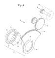
- FIG. 4 is an exploded perspective view of an actuator assembly for the limited slip differential assembly.
- an electronically controlled limited slip differential (LSD) assembly 10 in accordance with the present invention is utilized in a four-wheel-drive (FWD) vehicle 1 .
- the vehicle 1 comprises an engine 2 coupled to a four-wheel-drive transfer case 3 via a multi-speed change gear mechanism.
- the transfer case 3 is connected to a propeller shaft 4 for driving front wheels 5 of the vehicle 1 , and to a propeller shaft 7 for driving rear wheels 9 of the vehicle 1 through the electronically controlled differential assembly 10 .
- the differential assembly 10 is controlled by a control unit 80 .
- the control is carried out by judging vehicle running conditions according to wheel speeds and whether the brakes are applied inputted into the control unit 80 from wheel speed sensors 82 and a brake switch 84 .
- FIG. 2 of the drawings illustrates in detail the preferred arrangement of the differential assembly 10 in accordance with the present invention.
- Reference numeral 16 defines a differential case rotatably supported in a differential carrier 12 through roller bearings 14 , and defines an axis of rotation 17 .
- the differential case 16 is made of two halves 18 and 20 fastened to each other, preferably by means of bolts 22 .
- the differential assembly is provided with a set of pinion gears 24 rotatably supported on a pinion shaft 26 secured to the differential case 16 .
- the pinion gears 24 engage a pair of opposite side gears 28 adapted to rotate about the axis 17 .
- the side gears 28 are splined to output axle shafts 30 .
- a friction clutch assembly 32 is provided within the differential case 16 .
- the friction clutch assembly 32 well known in the prior art, includes sets of alternating outer friction plates 34 and inner friction plates 36 .
- an outer circumference of the outer friction plates 34 is provided with projections that non-rotatably engages corresponding grooves 38 formed in the differential case 16 .
- the outer friction plates 34 are slideable in axial direction.
- the inner friction plates 36 are splined to an annular thrust collar 40 disposed within the differential case 16 and adapted to actuate the clutch assembly 32 by axially loading the friction plates 34 and 36 .
- the thrust collar 40 is illustrated in detail in FIG. 3 .
- the thrust collar 40 includes hub portion 42 and an annular thrust flange 44 disposed between the hub portion 42 and a cylindrical tail portion 49 .
- the hub portion 42 is provided with splines 46 meshing with splines formed in a bore of the inner friction clutch plates 36 .
- the inner friction clutch plates 36 are non-rotatably, but axially slidably mounted on the thrust collar 40 .
- the annular thrust flange 44 is provided to axially load the friction clutch plates in order to actuate the friction clutch assembly 32 .
- the thrust collar 40 has a splined central bore 48 in sliding engagement with a splined end 31 of the axle shaft 30 , thus axially slidably, but non-rotatably coupling the thrust collar 40 to the axle shaft 30 .
- an annular separation plate 50 provided to separate the friction clutch assembly 32 from the side gear 28 .
- the friction clutch assembly 32 is confined in a space between the thrust collar 40 and the separation plate 50 .
- the separation plate 50 is spaced from the side gear 28 by a free running clearance therebetween.
- an axially endmost one of the friction clutch plates 34 , 36 forming the friction clutch assembly 32 abuts the separation plate 50 .
- one of the friction clutch plates 34 , 36 is engageable by the thrust collar 40 . Therefore, gear separating forces generated during the differential rotation between the side gears 28 , does not affect loading conditions of the friction clutch assembly 32 , i.e. friction clutch engagement, thus providing a limited slip differential capable to perform as an open differential.
- the differential assembly 10 further comprises an actuator assembly 52 which is controllable by the electronic control unit 80 based on the data from the vehicle wheel sensors 82 and the brake switch 84 , to cause the axial displacement of the thrust collar 40 in the direction of the friction clutch assembly 32 .
- actuator assembly 52 which is controllable by the electronic control unit 80 based on the data from the vehicle wheel sensors 82 and the brake switch 84 , to cause the axial displacement of the thrust collar 40 in the direction of the friction clutch assembly 32 .
- actuator assemblies known in the prior art may be used in the differential assembly of the present invention, such as hydraulic, electromagnetic, mechanical, etc.
- a preferred embodiment of the actuator assembly 52 is described below with the reference to FIGS. 2 and 4.
- the actuator assembly 52 comprises an electric servomotor 54 mounted to the differential carrier 12 and selectively controlled by the electronic control unit 80 , as a driving means.
- the servomotor 54 drives an actuating ring 60 , preferably through reduction gears 56 and 58 .
- the actuating ring 60 rotatable but axially constrained, is provided with a radially extended arcuate portion 62 formed with external gear teeth 64 meshing with teeth of the reduction gear 58 so that the rotation of the servomotor 54 causes the angular displacement of the actuating ring 60 , preferably less than 180°.
- the preferred embodiment of the actuator assembly 52 of the present invention includes a pressure collar 66 provided to apply an axial force to the thrust collar 40 in order to load the friction clutch assembly 32 .
- the pressure collar 66 is non-rotatably mounted to the differential carrier 12 , while capable to move axially.
- An axial thrust bearing 68 is provided between the pressure collar 66 and the thrust collar 40 to reduce the friction because the thrust collar 40 rotates with the axle shaft 30 .
- a pressure collar actuator 70 is disposed intermediate to the actuating ring 60 and the pressure collar 66 .
- the pressure collar actuator 70 is provided to convert the angular displacement of the actuating ring 60 into axial displacement of the pressure collar 66 .
- a ball-and-ramp actuator well known to those skilled in the art, is employed.
- an annular radial surface 67 of the pressure collar 66 facing the actuating ring 60 is formed with a set of circumferentially extending grooves 72 of varying axial depth, facing complementary grooves 74 in the actuating ring 60 , whose depth varies in the opposite circumferential sense.
- a corresponding number of balls 76 disposed between the pressure collar 66 and the actuating ring 60 one in each pair of the facing grooves 72 and 74 .
- a cam disc actuator including cooperative cam surfaces (not shown) provided on opposite sides of the actuating ring 60 and the pressure collar 66 , may be used as the pressure collar actuator.
- the electronically controlled differential assembly in accordance with the present invention represents a novel arrangement of the limited slip differential assembly that provides both limited slip and open differential capabilities.
Landscapes
- Engineering & Computer Science (AREA)
- General Engineering & Computer Science (AREA)
- Mechanical Engineering (AREA)
- Physics & Mathematics (AREA)
- Electromagnetism (AREA)
- Retarders (AREA)
- Mechanical Operated Clutches (AREA)
Abstract
Description
Claims (27)
Priority Applications (4)
| Application Number | Priority Date | Filing Date | Title |
|---|---|---|---|
| US09/643,232 US6398686B1 (en) | 2000-08-22 | 2000-08-22 | Electronically controlled limited slip differential assembly |
| AU58019/01A AU5801901A (en) | 2000-08-22 | 2001-08-14 | Electronically controlled limited slip differential assembly |
| JP2001248496A JP2002122213A (en) | 2000-08-22 | 2001-08-20 | Differential gear assembly |
| DE10140880A DE10140880A1 (en) | 2000-08-22 | 2001-08-21 | Electronically controlled limited slip differential assembly for motor vehicle, has selectively controllable actuator assembly to displace thrust collar in order to load friction clutch assembly |
Applications Claiming Priority (1)
| Application Number | Priority Date | Filing Date | Title |
|---|---|---|---|
| US09/643,232 US6398686B1 (en) | 2000-08-22 | 2000-08-22 | Electronically controlled limited slip differential assembly |
Publications (1)
| Publication Number | Publication Date |
|---|---|
| US6398686B1 true US6398686B1 (en) | 2002-06-04 |
Family
ID=24579924
Family Applications (1)
| Application Number | Title | Priority Date | Filing Date |
|---|---|---|---|
| US09/643,232 Expired - Fee Related US6398686B1 (en) | 2000-08-22 | 2000-08-22 | Electronically controlled limited slip differential assembly |
Country Status (4)
| Country | Link |
|---|---|
| US (1) | US6398686B1 (en) |
| JP (1) | JP2002122213A (en) |
| AU (1) | AU5801901A (en) |
| DE (1) | DE10140880A1 (en) |
Cited By (52)
| Publication number | Priority date | Publication date | Assignee | Title |
|---|---|---|---|---|
| US20020198076A1 (en) * | 2001-06-19 | 2002-12-26 | Mack Trucks, Inc. | Enclosed axle differential lock mechanism |
| US6533090B2 (en) * | 2001-08-03 | 2003-03-18 | Gkn Automotive, Inc. | Integrated axle module with twin electronic torque management |
| US20030054914A1 (en) * | 2001-09-19 | 2003-03-20 | Honda Giken Kogyo Kabushiki Kaisha | Limited slip differential |
| US6561939B1 (en) * | 2001-11-06 | 2003-05-13 | Torque-Traction Technologies, Inc. | Gear module for clutch actuator in differential assembly |
| US20030171182A1 (en) * | 2002-03-08 | 2003-09-11 | Gkn Automotive, Inc. | Alex module with axle shaft electronic management |
| US6626787B2 (en) | 2001-04-02 | 2003-09-30 | New Venture Gear, Inc. | On-demand all-wheel drive system |
| US6645109B2 (en) * | 2001-03-27 | 2003-11-11 | New Venture Gear, Inc. | Two-speed transfer case with ball-ramp clutch and single motor activator/shift system |
| US20040112702A1 (en) * | 2002-12-16 | 2004-06-17 | Stevenson Paul D. | Transmission torque-transmitting mechanism having a ball ramp electric motor apply mechanism |
| US6766889B1 (en) | 2003-02-11 | 2004-07-27 | New Venture Gear, Inc. | Wedge fork clutch actuator for driveline clutches |
| US20040149505A1 (en) * | 2001-04-02 | 2004-08-05 | Burns Timothy M. | Electronically-tuned hydromechanical coupling |
| US20040163916A1 (en) * | 2003-02-21 | 2004-08-26 | Showalter Dan Joseph | Single actuator lost motion shift assembly |
| US20040163919A1 (en) * | 2003-02-21 | 2004-08-26 | Kirkwood Malcolm E. | Torque transfer device with double ball screw clutch actuator |
| US20040173428A1 (en) * | 2003-03-07 | 2004-09-09 | Bowen Thomas C. | Worm driven ball screw actuator for traction clutches |
| US20040188216A1 (en) * | 2003-03-27 | 2004-09-30 | Nobushi Yamazaki | Torque transmission apparatus |
| US20040200655A1 (en) * | 2003-04-08 | 2004-10-14 | Mueller Joseph G. | On-demand transfer case |
| US20040226796A1 (en) * | 2001-07-05 | 2004-11-18 | Lars Severinsson | Ball arrangement in a torque transmitting device |
| US6840884B2 (en) | 2001-11-14 | 2005-01-11 | Xiaochun Wang | Fluctuating gear ratio limited-slip differential |
| US20050096172A1 (en) * | 2003-10-30 | 2005-05-05 | Mueller Joseph G. | Two-speed transfer case with adaptive clutch control |
| US20050113203A1 (en) * | 2003-11-24 | 2005-05-26 | Mueller Joseph G. | Clutch actuation system for two-speed active transfer case |
| US20050159264A1 (en) * | 2003-03-07 | 2005-07-21 | Dumitru Puiu | Torque vectoring drive units with worm driven ball screw clutches |
| EP1459927A3 (en) * | 2003-03-21 | 2005-08-24 | BorgWarner Inc. | Rear axle having electromagnetic clutches and geared differential |
| US20060046888A1 (en) * | 2004-08-30 | 2006-03-02 | Dumitru Puiu | Torque coupling with power-operated clutch actuator |
| US20060128515A1 (en) * | 2003-11-24 | 2006-06-15 | Mueller Joseph G | Two-speed transfer case |
| US20060163018A1 (en) * | 2005-01-26 | 2006-07-27 | Todd Ekonen | Power-operated clutch actuator for torque transfer mechanisms |
| GB2424251A (en) * | 2005-03-18 | 2006-09-20 | Dana Corp | Front-wheel-drive transaxle with limited slip differential |
| US20070023252A1 (en) * | 2005-07-28 | 2007-02-01 | Magna Powertrain Usa, Inc. | Power-operated clutch actuator for torque couplings |
| US20070034475A1 (en) * | 2005-08-11 | 2007-02-15 | Capito Russell T | Electronically-controlled hydraulically-actuated coupling |
| US20070049451A1 (en) * | 2005-09-01 | 2007-03-01 | Magna Powertrain Usa, Inc. | Two-speed transfer case with ballramp clutch actuator |
| US20070095628A1 (en) * | 2005-10-28 | 2007-05-03 | Magna Powertrain Usa, Inc. | Power-operated clutch actuator for torque transfer mechanisms |
| US20070215428A1 (en) * | 2005-08-11 | 2007-09-20 | American Axle & Manufacturing, Inc. | Electrohydraulic torque transfer device and control system |
| US20070251345A1 (en) * | 2006-04-26 | 2007-11-01 | Magna Powertrain Ag & Co Kg | Two-Speed Transfer Case With Adaptive Torque Transfer Clutch |
| US20080214355A1 (en) * | 2005-08-11 | 2008-09-04 | American Axle & Manufacturing, Inc. | Electrohydraulic Torque Transfer Device |
| US20090160152A1 (en) * | 2007-12-19 | 2009-06-25 | Gm Global Technology Operations, Inc. | Rearward Torque Arm for Damping Independently Suspended and Driven Axle Shafts |
| US20090294238A1 (en) * | 2008-05-30 | 2009-12-03 | American Axle & Manufacturing, Inc. | Electromechanical actuator for friction clutches |
| US20100012455A1 (en) * | 2005-04-28 | 2010-01-21 | Magna Powertrain Ag & Co. Kg | Power divider for motor vehicles comprising a controlled friction coupling |
| US7650808B2 (en) | 2006-02-03 | 2010-01-26 | Magna Powertrain Usa, Inc. | Sprial cam clutch actuation system for two-speed transfer case |
| US8197386B2 (en) | 2005-08-11 | 2012-06-12 | American Axle & Manufacturing, Inc. | Electrohydraulic torque transfer device and temperature control system |
| CN104006139A (en) * | 2014-06-03 | 2014-08-27 | 湖北航天技术研究院特种车辆技术中心 | Electronic limited slip differential mechanism |
| US9625024B2 (en) | 2013-06-14 | 2017-04-18 | Dana Automotive Systems Group, Llc | Differential with torque coupling |
| US9649931B2 (en) * | 2015-06-10 | 2017-05-16 | Gm Global Technology Operations, Llc | Vehicle differential assembly |
| US9701195B2 (en) | 2013-06-14 | 2017-07-11 | Dana Automotive Systems Group, Llc | Differential with torque coupling |
| US10012299B2 (en) | 2015-10-14 | 2018-07-03 | Dana Automotive Systems Group, Llc | Integrated active limited slip differential |
| US10197144B2 (en) | 2017-01-20 | 2019-02-05 | Dana Heavy Vehicle Systems Group, Llc | Drive unit with torque vectoring and an axle disconnect and reconnect mechanism |
| WO2019058233A1 (en) * | 2017-09-19 | 2019-03-28 | Bombardier Recreational Products Inc. | Control of a limited slip differential optimized for slippery driving conditions |
| US10408323B2 (en) | 2014-07-16 | 2019-09-10 | Dana Automotive Systems Group, Llc | Drive unit with twin side shaft torque coupling |
| US10836252B2 (en) | 2017-09-19 | 2020-11-17 | Bombardier Recreational Products Inc. | Control of a limited slip differential based on an engine torque |
| US10962097B2 (en) | 2017-09-19 | 2021-03-30 | Bombardier Recreational Products Inc. | Control of a limited slip differential based on a steering angle of a vehicle |
| US20220178404A1 (en) * | 2019-10-09 | 2022-06-09 | American Axle & Manufacturing, Inc. | Driveline component having lightweight ball-ramp mechanism |
| US11378167B2 (en) | 2017-09-19 | 2022-07-05 | Bombardier Recreational Products Inc. | Control of a limited slip differential based on an accelerator control position |
| RU2780680C2 (en) * | 2017-09-19 | 2022-09-29 | Бомбардье Рекриэйшенел Продактс Инк. | Control of limited slip differential, optimized for slippery driving conditions |
| US20250052309A1 (en) * | 2022-04-26 | 2025-02-13 | Gkn Automotive Limited | Variable characteristic limited-slip differential |
| DE102008061627B4 (en) * | 2007-12-19 | 2025-10-09 | GM Global Technology Operations LLC (n. d. Ges. d. Staates Delaware) | Individually suspended and driven axle shaft assembly, drive system configured therewith and method for reducing traction force vibrations in such an axle shaft assembly |
Families Citing this family (3)
| Publication number | Priority date | Publication date | Assignee | Title |
|---|---|---|---|---|
| DE10249247B4 (en) * | 2002-10-23 | 2010-08-26 | Man Nutzfahrzeuge Ag | Differential gearbox for commercial vehicles |
| DE10332496A1 (en) * | 2003-07-17 | 2005-02-10 | Zf Friedrichshafen Ag | Lockable differential gearing for automobile, has electric motor driving operating device for clutch coupling 2 drive shafts in locked position of compensation gearing |
| KR100796163B1 (en) | 2006-10-31 | 2008-01-21 | 다이모스(주) | Electronically Controlled Axle Module Of Vehicle |
Citations (11)
| Publication number | Priority date | Publication date | Assignee | Title |
|---|---|---|---|---|
| US4462272A (en) * | 1981-08-19 | 1984-07-31 | Rockwell International Corporation | Limited slip differential |
| US4662861A (en) | 1985-11-27 | 1987-05-05 | Canadian Fram Limited | Two speed accessory drive |
| US4805486A (en) | 1986-06-04 | 1989-02-21 | Tochigifujisangyo Kabushiki Kaisha | Locking differential gear assembly |
| US4950214A (en) | 1988-05-05 | 1990-08-21 | Uni-Cardan Ag | Differential drive |
| US5080640A (en) | 1989-06-07 | 1992-01-14 | Gkn Automotive Ag | Differential unit |
| US5092825A (en) | 1990-07-02 | 1992-03-03 | Eaton Corporation | Modulating limited slip differential |
| US5106349A (en) | 1989-05-18 | 1992-04-21 | Gkn Automotive Ag | Differential unit |
| US5279401A (en) | 1988-11-08 | 1994-01-18 | Uni-Cardan Ag | Method for controlling friction clutches or brakes |
| JPH08105512A (en) * | 1994-10-03 | 1996-04-23 | Tochigi Fuji Ind Co Ltd | Differential limiting device |
| US5732594A (en) | 1996-10-31 | 1998-03-31 | Ford Global Technologies, Inc. | Manual transmission with throttle actuated downshift |
| US6290623B1 (en) * | 1999-06-28 | 2001-09-18 | Dana Corporation | Removable support of motor vehicle differential side gear that facilitates machining |
Family Cites Families (1)
| Publication number | Priority date | Publication date | Assignee | Title |
|---|---|---|---|---|
| JPS62196951A (en) * | 1986-02-25 | 1987-08-31 | Canon Inc | Data transmission system |
-
2000
- 2000-08-22 US US09/643,232 patent/US6398686B1/en not_active Expired - Fee Related
-
2001
- 2001-08-14 AU AU58019/01A patent/AU5801901A/en not_active Abandoned
- 2001-08-20 JP JP2001248496A patent/JP2002122213A/en active Pending
- 2001-08-21 DE DE10140880A patent/DE10140880A1/en not_active Withdrawn
Patent Citations (11)
| Publication number | Priority date | Publication date | Assignee | Title |
|---|---|---|---|---|
| US4462272A (en) * | 1981-08-19 | 1984-07-31 | Rockwell International Corporation | Limited slip differential |
| US4662861A (en) | 1985-11-27 | 1987-05-05 | Canadian Fram Limited | Two speed accessory drive |
| US4805486A (en) | 1986-06-04 | 1989-02-21 | Tochigifujisangyo Kabushiki Kaisha | Locking differential gear assembly |
| US4950214A (en) | 1988-05-05 | 1990-08-21 | Uni-Cardan Ag | Differential drive |
| US5279401A (en) | 1988-11-08 | 1994-01-18 | Uni-Cardan Ag | Method for controlling friction clutches or brakes |
| US5106349A (en) | 1989-05-18 | 1992-04-21 | Gkn Automotive Ag | Differential unit |
| US5080640A (en) | 1989-06-07 | 1992-01-14 | Gkn Automotive Ag | Differential unit |
| US5092825A (en) | 1990-07-02 | 1992-03-03 | Eaton Corporation | Modulating limited slip differential |
| JPH08105512A (en) * | 1994-10-03 | 1996-04-23 | Tochigi Fuji Ind Co Ltd | Differential limiting device |
| US5732594A (en) | 1996-10-31 | 1998-03-31 | Ford Global Technologies, Inc. | Manual transmission with throttle actuated downshift |
| US6290623B1 (en) * | 1999-06-28 | 2001-09-18 | Dana Corporation | Removable support of motor vehicle differential side gear that facilitates machining |
Cited By (114)
| Publication number | Priority date | Publication date | Assignee | Title |
|---|---|---|---|---|
| US6966864B2 (en) | 2001-03-27 | 2005-11-22 | Magna Drivetrain Of America, Inc. | Two-speed transfer case with ball-ramp clutch and single motor activator/shift system |
| US6645109B2 (en) * | 2001-03-27 | 2003-11-11 | New Venture Gear, Inc. | Two-speed transfer case with ball-ramp clutch and single motor activator/shift system |
| US20040069509A1 (en) * | 2001-03-27 | 2004-04-15 | Williams Randolph C. | Transfer case for four-wheel drive vehicle |
| US20050070392A1 (en) * | 2001-03-27 | 2005-03-31 | Williams Randolph C. | Two-speed transfer case with ball-ramp clutch and single motor activator/shift system |
| US6824487B2 (en) | 2001-03-27 | 2004-11-30 | New Venture Gear, Inc. | Transfer case for four-wheel drive vehicle |
| US6953411B2 (en) | 2001-04-02 | 2005-10-11 | Magna Drivetrain Of America, Inc. | Electronically-tuned hydromechanical coupling |
| US6626787B2 (en) | 2001-04-02 | 2003-09-30 | New Venture Gear, Inc. | On-demand all-wheel drive system |
| US20040149505A1 (en) * | 2001-04-02 | 2004-08-05 | Burns Timothy M. | Electronically-tuned hydromechanical coupling |
| US20020198076A1 (en) * | 2001-06-19 | 2002-12-26 | Mack Trucks, Inc. | Enclosed axle differential lock mechanism |
| US20040248692A1 (en) * | 2001-06-19 | 2004-12-09 | Mack Trucks, Inc. | Enclosed axle differential lock mechanism |
| US20040226796A1 (en) * | 2001-07-05 | 2004-11-18 | Lars Severinsson | Ball arrangement in a torque transmitting device |
| US6533090B2 (en) * | 2001-08-03 | 2003-03-18 | Gkn Automotive, Inc. | Integrated axle module with twin electronic torque management |
| US6857982B2 (en) * | 2001-09-19 | 2005-02-22 | Honda Giken Kogyo Kabushiki Kaisha | Limited slip differential |
| US20030054914A1 (en) * | 2001-09-19 | 2003-03-20 | Honda Giken Kogyo Kabushiki Kaisha | Limited slip differential |
| US6561939B1 (en) * | 2001-11-06 | 2003-05-13 | Torque-Traction Technologies, Inc. | Gear module for clutch actuator in differential assembly |
| US6840884B2 (en) | 2001-11-14 | 2005-01-11 | Xiaochun Wang | Fluctuating gear ratio limited-slip differential |
| US20030171182A1 (en) * | 2002-03-08 | 2003-09-11 | Gkn Automotive, Inc. | Alex module with axle shaft electronic management |
| US6945899B2 (en) * | 2002-03-08 | 2005-09-20 | Gkn Driveline North America, Inc. | Axle module with axle shaft electronic management |
| US20040112702A1 (en) * | 2002-12-16 | 2004-06-17 | Stevenson Paul D. | Transmission torque-transmitting mechanism having a ball ramp electric motor apply mechanism |
| US6766889B1 (en) | 2003-02-11 | 2004-07-27 | New Venture Gear, Inc. | Wedge fork clutch actuator for driveline clutches |
| US20040188213A1 (en) * | 2003-02-11 | 2004-09-30 | Pennycuff Dale L. | Wedge fork clutch actuator for driveline clutches |
| US6938748B2 (en) | 2003-02-11 | 2005-09-06 | Magna Drivetrain Of America, Inc. | Wedge fork clutch actuator for driveline clutches |
| US20040163916A1 (en) * | 2003-02-21 | 2004-08-26 | Showalter Dan Joseph | Single actuator lost motion shift assembly |
| US6808052B2 (en) | 2003-02-21 | 2004-10-26 | New Venture Gear, Inc. | Torque transfer device with double ball screw clutch actuator |
| US20040163919A1 (en) * | 2003-02-21 | 2004-08-26 | Kirkwood Malcolm E. | Torque transfer device with double ball screw clutch actuator |
| US6802794B2 (en) * | 2003-02-21 | 2004-10-12 | Borgwarner, Inc. | Single actuator lost motion shift assembly |
| US6945375B2 (en) | 2003-02-21 | 2005-09-20 | Magna Drivetrain Of America, Inc. | Torque transfer device having an electric motor/brake actuator and friction clutch |
| US20040163918A1 (en) * | 2003-02-21 | 2004-08-26 | Kirkwood Malcolm E. | Torque transfer device having an electric motor/brake actuator and friction clutch |
| US20050079943A1 (en) * | 2003-02-21 | 2005-04-14 | Kirkwood Malcolm E. | Torque transfer device having an electric motor/brake actuator and friction clutch |
| US6808053B2 (en) | 2003-02-21 | 2004-10-26 | New Venture Gear, Inc. | Torque transfer device having an electric motor/brake actuator and friction clutch |
| US7175558B2 (en) | 2003-03-07 | 2007-02-13 | Magna Powertrain Usa, Inc. | Torque vectoring drive units with worm driven ball screw clutches |
| US6851537B2 (en) | 2003-03-07 | 2005-02-08 | Magna Drivetrain Of America, Inc. | Worm driven ball screw actuator for traction clutches |
| US20040173428A1 (en) * | 2003-03-07 | 2004-09-09 | Bowen Thomas C. | Worm driven ball screw actuator for traction clutches |
| US20050159264A1 (en) * | 2003-03-07 | 2005-07-21 | Dumitru Puiu | Torque vectoring drive units with worm driven ball screw clutches |
| EP1459927A3 (en) * | 2003-03-21 | 2005-08-24 | BorgWarner Inc. | Rear axle having electromagnetic clutches and geared differential |
| US20040188216A1 (en) * | 2003-03-27 | 2004-09-30 | Nobushi Yamazaki | Torque transmission apparatus |
| US7083033B2 (en) * | 2003-03-27 | 2006-08-01 | Tochigi Fuji Sangyo Kabushiki Kaisha | Torque transmission apparatus |
| US7178652B2 (en) | 2003-04-08 | 2007-02-20 | Magna Powertrain Usa, Inc. | Power transmission device having torque transfer mechanism with power-operated clutch actuator |
| US20060054373A1 (en) * | 2003-04-08 | 2006-03-16 | Mueller Joseph G | Power transmission device having torque transfer mechanism with power-operated clutch actuator |
| US20050023063A1 (en) * | 2003-04-08 | 2005-02-03 | Mueller Joseph G. | On-demand transfer case |
| US20040200655A1 (en) * | 2003-04-08 | 2004-10-14 | Mueller Joseph G. | On-demand transfer case |
| US6808037B1 (en) | 2003-04-08 | 2004-10-26 | New Venture Gear, Inc. | On-demand transfer case |
| US6964315B2 (en) | 2003-04-08 | 2005-11-15 | Magnadrivetrain Of America, Inc. | On-demand transfer case |
| US20050096172A1 (en) * | 2003-10-30 | 2005-05-05 | Mueller Joseph G. | Two-speed transfer case with adaptive clutch control |
| US7081064B2 (en) | 2003-10-30 | 2006-07-25 | Magna Powertrain Usa, Inc. | Two-speed transfer case with adaptive clutch control |
| US7229378B2 (en) | 2003-10-30 | 2007-06-12 | Magna Powertrain Usa, Inc. | Shift system for transfer case |
| US6905436B2 (en) | 2003-10-30 | 2005-06-14 | Magna Drivetrain Of America, Inc. | Two-speed transfer case with adaptive clutch control |
| US20060247082A1 (en) * | 2003-10-30 | 2006-11-02 | Magna Powertrain Usa, Inc. | Shift system for transfer case |
| US20050202919A1 (en) * | 2003-11-24 | 2005-09-15 | Mueller Joseph G. | Clutch actuation system for two-speed active transfer case |
| US7033300B2 (en) | 2003-11-24 | 2006-04-25 | Magna Powertrain, Inc. | Clutch actuation system for two-speed active transfer case |
| US20060128515A1 (en) * | 2003-11-24 | 2006-06-15 | Mueller Joseph G | Two-speed transfer case |
| US7399251B2 (en) | 2003-11-24 | 2008-07-15 | Magna Powertrain Usa, Inc. | Two-speed transfer case |
| US6929577B2 (en) | 2003-11-24 | 2005-08-16 | Magna Drivetrain Of America, Inc. | Clutch actuation system for two-speed active transfer case |
| US20050113203A1 (en) * | 2003-11-24 | 2005-05-26 | Mueller Joseph G. | Clutch actuation system for two-speed active transfer case |
| US20060046888A1 (en) * | 2004-08-30 | 2006-03-02 | Dumitru Puiu | Torque coupling with power-operated clutch actuator |
| US7338403B2 (en) | 2004-08-30 | 2008-03-04 | Magna Powertrain Usa, Inc. | Torque coupling with power-operated clutch actuator |
| US20060272876A1 (en) * | 2005-01-26 | 2006-12-07 | Magna Powertrain Usa, Inc. | Power transmission devices having torque transfer coupling with power-operated clutch actuator |
| US7258213B2 (en) | 2005-01-26 | 2007-08-21 | Magna Powertrain Usa, Inc. | Power transmission devices having torque transfer coupling with power-operated clutch actuator |
| US20060163018A1 (en) * | 2005-01-26 | 2006-07-27 | Todd Ekonen | Power-operated clutch actuator for torque transfer mechanisms |
| US7111716B2 (en) | 2005-01-26 | 2006-09-26 | Magna Powertrain Usa, Inc. | Power-operated clutch actuator for torque transfer mechanisms |
| GB2424251A (en) * | 2005-03-18 | 2006-09-20 | Dana Corp | Front-wheel-drive transaxle with limited slip differential |
| US20060211532A1 (en) * | 2005-03-18 | 2006-09-21 | Krisher James A | Torque-coupling device for front-wheel-drive transaxle unit |
| GB2424251B (en) * | 2005-03-18 | 2010-01-06 | Dana Corp | Torque-coupling device for front-wheel-drive transaxle unit |
| US7390278B2 (en) | 2005-03-18 | 2008-06-24 | Dana Automotive Systems Group, Llc. | Torque-coupling device for front-wheel-drive transaxle unit |
| US20100012455A1 (en) * | 2005-04-28 | 2010-01-21 | Magna Powertrain Ag & Co. Kg | Power divider for motor vehicles comprising a controlled friction coupling |
| US8091451B2 (en) | 2005-04-28 | 2012-01-10 | Magna Powertrain Ag & Co Kg | Power divider for motor vehicles comprising a controlled friction coupling |
| US7686149B2 (en) | 2005-07-28 | 2010-03-30 | Magna Powertrain Usa, Inc. | Power transmission device with friction clutch and power-operated clutch actuator |
| US20090211869A1 (en) * | 2005-07-28 | 2009-08-27 | Magna Powertrain Usa, Inc. | Power Transmission Device With Friction Clutch And Power-Operated Clutch Actuator |
| US7527133B2 (en) | 2005-07-28 | 2009-05-05 | Magna Powertrain Usa, Inc. | Power-operated clutch actuator for torque couplings |
| US20070023252A1 (en) * | 2005-07-28 | 2007-02-01 | Magna Powertrain Usa, Inc. | Power-operated clutch actuator for torque couplings |
| US20070215428A1 (en) * | 2005-08-11 | 2007-09-20 | American Axle & Manufacturing, Inc. | Electrohydraulic torque transfer device and control system |
| US8083041B2 (en) | 2005-08-11 | 2011-12-27 | American Axle & Manufacturing, Inc. | Electrohydraulic torque transfer device |
| US7445106B2 (en) | 2005-08-11 | 2008-11-04 | American Axle & Manufacturing, Inc. | Electronically-controlled hydraulically-actuated coupling |
| US20070034475A1 (en) * | 2005-08-11 | 2007-02-15 | Capito Russell T | Electronically-controlled hydraulically-actuated coupling |
| US8197386B2 (en) | 2005-08-11 | 2012-06-12 | American Axle & Manufacturing, Inc. | Electrohydraulic torque transfer device and temperature control system |
| US20080214355A1 (en) * | 2005-08-11 | 2008-09-04 | American Axle & Manufacturing, Inc. | Electrohydraulic Torque Transfer Device |
| US20100243397A1 (en) * | 2005-08-11 | 2010-09-30 | Capito Russell T | Electronically-controlled hydraulically-actuated coupling |
| US20080287250A1 (en) * | 2005-08-11 | 2008-11-20 | Capito Russell T | Electronically-controlled hydraulically-actuated coupling |
| US8016093B2 (en) | 2005-08-11 | 2011-09-13 | American Axle & Manufacturing, Inc. | Electronically-controlled hydraulically-actuated coupling |
| US7743899B2 (en) | 2005-08-11 | 2010-06-29 | American Axle & Manufacturing, Inc. | Electrohydraulic torque transfer device and control system |
| US20070049451A1 (en) * | 2005-09-01 | 2007-03-01 | Magna Powertrain Usa, Inc. | Two-speed transfer case with ballramp clutch actuator |
| US7540820B2 (en) | 2005-09-01 | 2009-06-02 | Magna Powertrain Usa, Inc. | Two-speed transfer case with ballramp clutch actuator |
| US20070095628A1 (en) * | 2005-10-28 | 2007-05-03 | Magna Powertrain Usa, Inc. | Power-operated clutch actuator for torque transfer mechanisms |
| US7650808B2 (en) | 2006-02-03 | 2010-01-26 | Magna Powertrain Usa, Inc. | Sprial cam clutch actuation system for two-speed transfer case |
| US7694598B2 (en) | 2006-04-26 | 2010-04-13 | Magna Powertrain Ag & Co Kg | Two-speed transfer case with adaptive torque transfer clutch |
| US20070251345A1 (en) * | 2006-04-26 | 2007-11-01 | Magna Powertrain Ag & Co Kg | Two-Speed Transfer Case With Adaptive Torque Transfer Clutch |
| US7874398B2 (en) | 2007-12-19 | 2011-01-25 | GM Global Technology Operations LLC | Rearward torque arm for damping independently suspended and driven axle shafts |
| DE102008061627B4 (en) * | 2007-12-19 | 2025-10-09 | GM Global Technology Operations LLC (n. d. Ges. d. Staates Delaware) | Individually suspended and driven axle shaft assembly, drive system configured therewith and method for reducing traction force vibrations in such an axle shaft assembly |
| US20090159359A1 (en) * | 2007-12-19 | 2009-06-25 | Gm Global Technology Operations, Inc. | Independently Suspended and Driven Asymmetric Axle Shafts |
| US20090160152A1 (en) * | 2007-12-19 | 2009-06-25 | Gm Global Technology Operations, Inc. | Rearward Torque Arm for Damping Independently Suspended and Driven Axle Shafts |
| US7938222B2 (en) * | 2007-12-19 | 2011-05-10 | GM Global Technology Operations LLC | Independently suspended and driven asymmetric axle shafts |
| US20090294238A1 (en) * | 2008-05-30 | 2009-12-03 | American Axle & Manufacturing, Inc. | Electromechanical actuator for friction clutches |
| US8534439B2 (en) | 2008-05-30 | 2013-09-17 | American Axle & Manufacturing, Inc. | Electromechanical actuator for friction clutches |
| US9701195B2 (en) | 2013-06-14 | 2017-07-11 | Dana Automotive Systems Group, Llc | Differential with torque coupling |
| US9625024B2 (en) | 2013-06-14 | 2017-04-18 | Dana Automotive Systems Group, Llc | Differential with torque coupling |
| CN104006139B (en) * | 2014-06-03 | 2016-09-14 | 湖北航天技术研究院特种车辆技术中心 | A kind of electronic limited slip differential device |
| CN104006139A (en) * | 2014-06-03 | 2014-08-27 | 湖北航天技术研究院特种车辆技术中心 | Electronic limited slip differential mechanism |
| US10408323B2 (en) | 2014-07-16 | 2019-09-10 | Dana Automotive Systems Group, Llc | Drive unit with twin side shaft torque coupling |
| US9649931B2 (en) * | 2015-06-10 | 2017-05-16 | Gm Global Technology Operations, Llc | Vehicle differential assembly |
| US10012299B2 (en) | 2015-10-14 | 2018-07-03 | Dana Automotive Systems Group, Llc | Integrated active limited slip differential |
| US10197144B2 (en) | 2017-01-20 | 2019-02-05 | Dana Heavy Vehicle Systems Group, Llc | Drive unit with torque vectoring and an axle disconnect and reconnect mechanism |
| WO2019058233A1 (en) * | 2017-09-19 | 2019-03-28 | Bombardier Recreational Products Inc. | Control of a limited slip differential optimized for slippery driving conditions |
| US10836252B2 (en) | 2017-09-19 | 2020-11-17 | Bombardier Recreational Products Inc. | Control of a limited slip differential based on an engine torque |
| US10962097B2 (en) | 2017-09-19 | 2021-03-30 | Bombardier Recreational Products Inc. | Control of a limited slip differential based on a steering angle of a vehicle |
| US11378167B2 (en) | 2017-09-19 | 2022-07-05 | Bombardier Recreational Products Inc. | Control of a limited slip differential based on an accelerator control position |
| US11383599B2 (en) | 2017-09-19 | 2022-07-12 | Bombardier Recreational Products Inc. | Control of a limited slip differential based on an engine torque |
| RU2780680C2 (en) * | 2017-09-19 | 2022-09-29 | Бомбардье Рекриэйшенел Продактс Инк. | Control of limited slip differential, optimized for slippery driving conditions |
| US11674578B2 (en) | 2017-09-19 | 2023-06-13 | Bombardier Recreational Products Inc. | Control of a limited slip differential optimized for slippery driving conditions |
| CN111094797B (en) * | 2017-09-19 | 2023-10-27 | 庞巴迪动力产品公司 | Control of limited-slip differential optimized for slippery driving conditions |
| CN111094797A (en) * | 2017-09-19 | 2020-05-01 | 庞巴迪动力产品公司 | Control of limited slip differential optimized for wet driving conditions |
| US20220178404A1 (en) * | 2019-10-09 | 2022-06-09 | American Axle & Manufacturing, Inc. | Driveline component having lightweight ball-ramp mechanism |
| US11940014B2 (en) * | 2019-10-09 | 2024-03-26 | American Axle & Manufacturing, Inc. | Driveline component having lightweight ball-ramp mechanism |
| US20250052309A1 (en) * | 2022-04-26 | 2025-02-13 | Gkn Automotive Limited | Variable characteristic limited-slip differential |
| US12385558B2 (en) * | 2022-04-26 | 2025-08-12 | Gkn Automotive Limited | Variable characteristic limited-slip differential |
Also Published As
| Publication number | Publication date |
|---|---|
| AU5801901A (en) | 2002-02-28 |
| DE10140880A1 (en) | 2002-05-08 |
| JP2002122213A (en) | 2002-04-26 |
Similar Documents
| Publication | Publication Date | Title |
|---|---|---|
| US6398686B1 (en) | Electronically controlled limited slip differential assembly | |
| US6561939B1 (en) | Gear module for clutch actuator in differential assembly | |
| US5971123A (en) | Bi-directional overrunning clutch | |
| US6827663B2 (en) | Differential gear | |
| US9022195B2 (en) | Bi-directional overrunning clutch having split roll cage and drag mechanism | |
| US9309957B2 (en) | Locking differential having combination preload springs for maintained contact | |
| US6537172B1 (en) | Electronically actuated modulatable differential | |
| JPH11125280A (en) | Clutch with magnetical-rheological actuating device for transfer case, etc. | |
| US6481548B2 (en) | Two-way clutch with limited slip feature | |
| US9303748B2 (en) | Collapsible clutching differential | |
| US5215506A (en) | Electronically controlled differential limiting system | |
| US7390278B2 (en) | Torque-coupling device for front-wheel-drive transaxle unit | |
| CN104411528B (en) | Locking differential with reloading spring wear-resistant pad | |
| WO2013109703A1 (en) | Two-mode passive limited slip differential | |
| US9151376B2 (en) | Locking differential having dampening communication spring | |
| US4966265A (en) | Clutch | |
| US20220136569A1 (en) | Torque transmission device for a motor vehicle | |
| US6742640B1 (en) | Wrap spring activated torque transfer device | |
| US6554732B1 (en) | Differential assembly with modified limited slip clutch arrangement | |
| CN220416145U (en) | Electric control locking limited slip differential | |
| KR20040016966A (en) | A ball arrangement in a torque transmitting device | |
| AU1871802A (en) | Eclipse roller drive direction sensing differential |
Legal Events
| Date | Code | Title | Description |
|---|---|---|---|
| AS | Assignment |
Owner name: DANA CORPORATION, OHIO Free format text: ASSIGNMENT OF ASSIGNORS INTEREST;ASSIGNOR:IRWIN, EARL JAMES;REEL/FRAME:011031/0052 Effective date: 20000821 |
|
| AS | Assignment |
Owner name: SPICER TECHNOLOGY, INC., INDIANA Free format text: ASSIGNMENT OF ASSIGNORS INTEREST;ASSIGNOR:DANA CORPORATION;REEL/FRAME:012607/0547 Effective date: 20020218 |
|
| AS | Assignment |
Owner name: TORQUE-TRACTION TECHNOLOGIES, INC., OHIO Free format text: MERGER /CHANGE OF NAME;ASSIGNORS:SPICER TECHNOLOGY, INC.;SPICER DRIVESHAFT, INC.;REEL/FRAME:014646/0285 Effective date: 20021231 Owner name: TORQUE-TRACTION TECHNOLOGIES, INC., OHIO Free format text: MERGER AND CHANGE OF NAME;ASSIGNORS:SPICER TECHNOLOGY, INC.;SPICER DRIVESHAFT, INC.;REEL/FRAME:013943/0214 Effective date: 20021231 |
|
| FPAY | Fee payment |
Year of fee payment: 4 |
|
| AS | Assignment |
Owner name: TORQUE-TRACTION TECHNOLOGIES LLC, OHIO Free format text: MERGER;ASSIGNOR:TORQUE-TRACTION TECHNOLOGY, INC.;REEL/FRAME:017240/0209 Effective date: 20060101 |
|
| AS | Assignment |
Owner name: DANA AUTOMOTIVE SYSTEMS GROUP, LLC, OHIO Free format text: ASSIGNMENT OF ASSIGNORS INTEREST;ASSIGNOR:TORQUE-TRACTION TECHNOLOGIES, LLC;REEL/FRAME:020518/0949 Effective date: 20080131 Owner name: DANA AUTOMOTIVE SYSTEMS GROUP, LLC,OHIO Free format text: ASSIGNMENT OF ASSIGNORS INTEREST;ASSIGNOR:TORQUE-TRACTION TECHNOLOGIES, LLC;REEL/FRAME:020518/0949 Effective date: 20080131 |
|
| AS | Assignment |
Owner name: CITICORP USA, INC., NEW YORK Free format text: INTELLECTUAL PROPERTY REVOLVING FACILITY SECURITY AGREEMENT;ASSIGNORS:DANA HOLDING CORPORATION;DANA LIMITED;DANA AUTOMOTIVE SYSTEMS GROUP, LLC;AND OTHERS;REEL/FRAME:020859/0249 Effective date: 20080131 Owner name: CITICORP USA, INC.,NEW YORK Free format text: INTELLECTUAL PROPERTY REVOLVING FACILITY SECURITY AGREEMENT;ASSIGNORS:DANA HOLDING CORPORATION;DANA LIMITED;DANA AUTOMOTIVE SYSTEMS GROUP, LLC;AND OTHERS;REEL/FRAME:020859/0249 Effective date: 20080131 Owner name: CITICORP USA, INC., NEW YORK Free format text: INTELLECTUAL PROPERTY TERM FACILITY SECURITY AGREEMENT;ASSIGNORS:DANA HOLDING CORPORATION;DANA LIMITED;DANA AUTOMOTIVE SYSTEMS GROUP, LLC;AND OTHERS;REEL/FRAME:020859/0359 Effective date: 20080131 Owner name: CITICORP USA, INC.,NEW YORK Free format text: INTELLECTUAL PROPERTY TERM FACILITY SECURITY AGREEMENT;ASSIGNORS:DANA HOLDING CORPORATION;DANA LIMITED;DANA AUTOMOTIVE SYSTEMS GROUP, LLC;AND OTHERS;REEL/FRAME:020859/0359 Effective date: 20080131 |
|
| FPAY | Fee payment |
Year of fee payment: 8 |
|
| FEPP | Fee payment procedure |
Free format text: PAYOR NUMBER ASSIGNED (ORIGINAL EVENT CODE: ASPN); ENTITY STATUS OF PATENT OWNER: LARGE ENTITY |
|
| REMI | Maintenance fee reminder mailed | ||
| LAPS | Lapse for failure to pay maintenance fees | ||
| STCH | Information on status: patent discontinuation |
Free format text: PATENT EXPIRED DUE TO NONPAYMENT OF MAINTENANCE FEES UNDER 37 CFR 1.362 |
|
| FP | Lapsed due to failure to pay maintenance fee |
Effective date: 20140604 |