US6393949B1 - Ratchet screwdriver - Google Patents
Ratchet screwdriver Download PDFInfo
- Publication number
- US6393949B1 US6393949B1 US09/748,444 US74844400A US6393949B1 US 6393949 B1 US6393949 B1 US 6393949B1 US 74844400 A US74844400 A US 74844400A US 6393949 B1 US6393949 B1 US 6393949B1
- Authority
- US
- United States
- Prior art keywords
- main body
- switching
- ratchet
- block
- stop blocks
- Prior art date
- Legal status (The legal status is an assumption and is not a legal conclusion. Google has not performed a legal analysis and makes no representation as to the accuracy of the status listed.)
- Expired - Fee Related
Links
Images


Classifications
-
- B—PERFORMING OPERATIONS; TRANSPORTING
- B25—HAND TOOLS; PORTABLE POWER-DRIVEN TOOLS; MANIPULATORS
- B25G—HANDLES FOR HAND IMPLEMENTS
- B25G1/00—Handle constructions
- B25G1/06—Handle constructions reversible or adjustable for position
- B25G1/063—Handle constructions reversible or adjustable for position for screwdrivers, wrenches or spanners
-
- B—PERFORMING OPERATIONS; TRANSPORTING
- B25—HAND TOOLS; PORTABLE POWER-DRIVEN TOOLS; MANIPULATORS
- B25B—TOOLS OR BENCH DEVICES NOT OTHERWISE PROVIDED FOR, FOR FASTENING, CONNECTING, DISENGAGING OR HOLDING
- B25B15/00—Screwdrivers
- B25B15/02—Screwdrivers operated by rotating the handle
- B25B15/04—Screwdrivers operated by rotating the handle with ratchet action
Definitions
- the present invention relates generally to a hand tool, and more particularly to a ratchet screwdriver.
- a ratchet screwdriver 10 of the prior art comprises a handle 11 having a main body 12 which is provided at the front end thereof with a shaft hole 14 with a core hole 13 .
- a shaft 17 is pivoted to the shaft hole 14 and is provided with a gear 15 and a protruded pillar 16 .
- a stop plate 19 is disposed in an insertion slot 18 of the main body 12 .
- the gear 15 is actuated by two check plates 20 which are provided with a dial button seat 22 having two elastic press plates 21 .
- a housing 24 is fitted over the main body 12 such that a retaining cut 25 of the housing 24 is engaged with a projection 26 of the main body 12 .
- the housing 24 has a position confining hole 23 .
- the main body 12 is further provided with a locking member 28 having a bearing hole 27 which is slidably fitted over the shaft 17 .
- the prior art ratchet screwdriver 10 is defective in design because the main body 12 is not provided with sufficient torsional strength, because the check plates 20 are too thin, and because the adjustment of the dial button seat 22 cannot be easily done, and also because assembly of the ratchet screwdriver 10 is not cost-effective.
- the primary objective of the present invention is to provide a ratchet screwdriver which is free of the deficiencies of the prior art ratchet screwdriver described above.
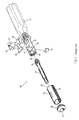
- FIG. 1 shows an exploded view of a ratchet screwdriver of the prior art.
- FIG. 2 shows a perspective view of the ratchet screwdriver of the prior art.
- FIG. 3 shows a perspective view of the present invention.
- FIG. 4 shows an exploded view of the present invention.
- FIGS. 5-7 are cross-sectional views of the present invention.
- FIG. 8 shows a longitudinal sectional view of the present invention.
- FIG. 9 shows a partial sectional view of the present invention.
- a ratchet screwdriver 30 of the present invention comprises a main body 35 , a ratchet rod 34 , a shell tube 31 , a switching ring 32 , a pressing member 33 , two stop blocks 36 , a switching block 37 , a locating member 38 , and a recovery elastic piece.
- the main body 35 is provided at one end with an outer threaded portion 354 and is further provided in the interior with a receiving space in which the ratchet rod 34 , the switching block 37 , and two stop blocks 36 are disposed.
- the main body 35 is also provided in the outer edge thereof with two receiving holes 351 for two stop blocks 36 to be disposed in the receiving space of the interior of the main body.
- the main body 35 is further provided with an elastic piece retaining groove 352 and a locating member groove 353 in which the locating member 38 is retained.
- the recovery elastic piece 39 is retained in the elastic piece retaining groove 352 .
- the shell tube 31 is fitted over the main body 35 such that the switching ring 32 is fitted over the shell tube 31 , and such that the outer threaded portion 354 is engaged with an inner threaded portion 331 of the pressing member 33 .
- the ratchet rod 34 is provided with an annular groove 342 and a ratchet tooth 341 and is capable of one-way position confinement.
- the shell tube 31 is fitted over the main body 35 and is provided at one end with the switch ring 32 which is provided with a retaining groove 321 for retaining a protruded block 371 of the switching block 37 .
- the pressing member 33 is provided in the inner wall with inner threads 331 which are engaged with the outer threaded portion 354 of the main body 35 for locating the switching ring 32 and the shell tube 31 on the main body 35 .
- the two stop blocks 36 are disposed in the interior of the main body 35 so as to cooperate with the ratchet tooth 341 of the ratchet rod 34 .
- the switching block 37 is provided with a protruded block 371 and is disposed in the interior of the main body 35 such that the switching block 37 is retained in the annular groove 342 of the ratchet rod 34 , such that the switching block 37 presses against the stop blocks 36 , and such that the protruded block 371 of the switching block 37 is retained in the retaining groove 321 of the switching ring 32 .
- the locating member 38 is provided with a locating segment 381 and a fixation end 382 .
- the locating segment 381 is retained in the locating member retaining groove 353 of the main body 35 .
- the recovery elastic piece 39 is of a curved construction and is retained in the elastic piece retaining groove 352 of the main body 35 such that the recovery elastic piece 39 is rested against the two stop blocks 36 .
- the tip is retained by the ratchet rod 34 .
- the switching block 37 is linked to turn on the annular groove 342 of the ratchet rod 34 , thereby causing one of the two pointed top portions of the switching block 37 to push one stop block 36 upward to move away from the rotating track of the ratchet tooth 341 .
- the Other one of the two pointed top portions of the switching block 37 moves away from other stop block 36 .
- the ratchet screwdriver 30 is capable of one-way rotation.
Landscapes
- Engineering & Computer Science (AREA)
- Mechanical Engineering (AREA)
- Details Of Spanners, Wrenches, And Screw Drivers And Accessories (AREA)
Abstract
A ratchet screwdriver including a main body, two stop blocks, a switching block, a locating member, a recovery elastic piece. The main body is provided with an outer threaded portion having a hole for receiving a ratchet rod. A shell tube is fitted over the main body such that a switching ring is fitted over the shell tube. The switching ring is provided with a retaining groove for retaining a protruded block of the switching block. The shell tube and the switching ring are pressed against the main body by a pressing member having inner threads which are engaged with the outer threaded portion of the main body.
Description
1. Field of the Invention
The present invention relates generally to a hand tool, and more particularly to a ratchet screwdriver.
2. Description of Related Art
As shown in FIGS. 1 and 2, a ratchet screwdriver 10 of the prior art comprises a handle 11 having a main body 12 which is provided at the front end thereof with a shaft hole 14 with a core hole 13. A shaft 17 is pivoted to the shaft hole 14 and is provided with a gear 15 and a protruded pillar 16. A stop plate 19 is disposed in an insertion slot 18 of the main body 12. The gear 15 is actuated by two check plates 20 which are provided with a dial button seat 22 having two elastic press plates 21. A housing 24 is fitted over the main body 12 such that a retaining cut 25 of the housing 24 is engaged with a projection 26 of the main body 12. The housing 24 has a position confining hole 23. The main body 12 is further provided with a locking member 28 having a bearing hole 27 which is slidably fitted over the shaft 17.
The prior art ratchet screwdriver 10 is defective in design because the main body 12 is not provided with sufficient torsional strength, because the check plates 20 are too thin, and because the adjustment of the dial button seat 22 cannot be easily done, and also because assembly of the ratchet screwdriver 10 is not cost-effective.
The primary objective of the present invention is to provide a ratchet screwdriver which is free of the deficiencies of the prior art ratchet screwdriver described above.
The features and the advantages of the present invention will be readily understood upon a thoughtful deliberation of the following detailed description of the present invention with reference to the accompanying drawings.
FIG. 1 shows an exploded view of a ratchet screwdriver of the prior art.
FIG. 2 shows a perspective view of the ratchet screwdriver of the prior art.
FIG. 3 shows a perspective view of the present invention.
FIG. 4 shows an exploded view of the present invention.
FIGS. 5-7 are cross-sectional views of the present invention.
FIG. 8 shows a longitudinal sectional view of the present invention.
FIG. 9 shows a partial sectional view of the present invention.
As shown in FIGS. 3-9, a ratchet screwdriver 30 of the present invention comprises a main body 35, a ratchet rod 34, a shell tube 31, a switching ring 32, a pressing member 33, two stop blocks 36, a switching block 37, a locating member 38, and a recovery elastic piece.
The main body 35 is provided at one end with an outer threaded portion 354 and is further provided in the interior with a receiving space in which the ratchet rod 34, the switching block 37, and two stop blocks 36 are disposed. The main body 35 is also provided in the outer edge thereof with two receiving holes 351 for two stop blocks 36 to be disposed in the receiving space of the interior of the main body. The main body 35 is further provided with an elastic piece retaining groove 352 and a locating member groove 353 in which the locating member 38 is retained. The recovery elastic piece 39 is retained in the elastic piece retaining groove 352. The shell tube 31 is fitted over the main body 35 such that the switching ring 32 is fitted over the shell tube 31, and such that the outer threaded portion 354 is engaged with an inner threaded portion 331 of the pressing member 33.
The ratchet rod 34 is provided with an annular groove 342 and a ratchet tooth 341 and is capable of one-way position confinement.
The shell tube 31 is fitted over the main body 35 and is provided at one end with the switch ring 32 which is provided with a retaining groove 321 for retaining a protruded block 371 of the switching block 37.
The pressing member 33 is provided in the inner wall with inner threads 331 which are engaged with the outer threaded portion 354 of the main body 35 for locating the switching ring 32 and the shell tube 31 on the main body 35.
The two stop blocks 36 are disposed in the interior of the main body 35 so as to cooperate with the ratchet tooth 341 of the ratchet rod 34.
The switching block 37 is provided with a protruded block 371 and is disposed in the interior of the main body 35 such that the switching block 37 is retained in the annular groove 342 of the ratchet rod 34, such that the switching block 37 presses against the stop blocks 36, and such that the protruded block 371 of the switching block 37 is retained in the retaining groove 321 of the switching ring 32.
The locating member 38 is provided with a locating segment 381 and a fixation end 382. The locating segment 381 is retained in the locating member retaining groove 353 of the main body 35.
The recovery elastic piece 39 is of a curved construction and is retained in the elastic piece retaining groove 352 of the main body 35 such that the recovery elastic piece 39 is rested against the two stop blocks 36.
In operation, the tip is retained by the ratchet rod 34. As the switching ring 32 is turned, the switching block 37 is linked to turn on the annular groove 342 of the ratchet rod 34, thereby causing one of the two pointed top portions of the switching block 37 to push one stop block 36 upward to move away from the rotating track of the ratchet tooth 341. the Other one of the two pointed top portions of the switching block 37 moves away from other stop block 36. As a result, the ratchet screwdriver 30 is capable of one-way rotation.
Claims (1)
1. A ratchet screwdriver comprising:
a main body having an outer threaded portion at one end thereof, said main body having a receiving space in an interior thereof, said main body having a retaining groove and a locating groove;
a shell tube fitted over said main body, said shell tube having a switching ring at one end thereof, said shell tube having a retaining groove therein;
a pressing member having inner threads in an inner wall thereof, said inner threads engaged with said outer threaded portion of said main body, said pressing member retaining said switching ring and said shell tube on said main body;
a ratchet rod having an annular groove and ratchet teeth, said ratchet rod disposed in said receiving space of said main body;
two stop blocks disposed in said receiving space of said main body, said two stop blocks cooperative with said ratchet teeth of ratchet rod;
a switching block disposed in said receiving space of said main body, said switching block having a protruded block, said switching block retained in said annular groove of said ratchet rod such that said switching block bears against said stop blocks, said protruded block of said switching block being retained in said retaining groove of said switching ring;
a locating member having a locating segment and a fixation end, said locating segment being retained in said locating groove of said main body; and
a recovery elastic piece retained in said retaining groove of said main body, said recovery elastic piece having ends bearing respectively on said stop blocks on a side of said stop blocks opposite said switching block.
Priority Applications (1)
| Application Number | Priority Date | Filing Date | Title |
|---|---|---|---|
| US09/748,444 US6393949B1 (en) | 2000-12-27 | 2000-12-27 | Ratchet screwdriver |
Applications Claiming Priority (1)
| Application Number | Priority Date | Filing Date | Title |
|---|---|---|---|
| US09/748,444 US6393949B1 (en) | 2000-12-27 | 2000-12-27 | Ratchet screwdriver |
Publications (1)
| Publication Number | Publication Date |
|---|---|
| US6393949B1 true US6393949B1 (en) | 2002-05-28 |
Family
ID=25009463
Family Applications (1)
| Application Number | Title | Priority Date | Filing Date |
|---|---|---|---|
| US09/748,444 Expired - Fee Related US6393949B1 (en) | 2000-12-27 | 2000-12-27 | Ratchet screwdriver |
Country Status (1)
| Country | Link |
|---|---|
| US (1) | US6393949B1 (en) |
Cited By (11)
| Publication number | Priority date | Publication date | Assignee | Title |
|---|---|---|---|---|
| US20020043134A1 (en) * | 2000-10-12 | 2002-04-18 | Shih-Chi Ho | Locating and shifting structures of a movable joint of a ratchet screwdriver |
| EP1547727A1 (en) * | 2003-12-23 | 2005-06-29 | Chia Yu Chen | Tool having an angularly adjustable driving head |
| EP1563963A1 (en) * | 2004-02-16 | 2005-08-17 | Felo-Werkzeugfabrik Holland-Letz Gmbh | Screwdriver with holding device |
| US20050211027A1 (en) * | 2004-03-25 | 2005-09-29 | Zu-Shung Shu | Selective one-way bit-driving apparatus |
| US7028587B1 (en) * | 2005-07-15 | 2006-04-18 | Shu Chi Chiang | Ratchet tool |
| US20080033559A1 (en) * | 2002-10-29 | 2008-02-07 | Zucherman James F | Interspinous process implants and methods of use |
| US20080154278A1 (en) * | 2005-05-23 | 2008-06-26 | Custom Spine, Inc. | Ratcheting torque wrench |
| US20110004222A1 (en) * | 2009-04-07 | 2011-01-06 | Lutz Biedermann | Tool for Use with a Bone Anchor, in Particular for Spinal Surgery |
| US20150047473A1 (en) * | 2013-08-14 | 2015-02-19 | Lawrence Ryans | Compact Gas Cylinder Valve Ratchet Driver Tool |
| US9056391B1 (en) * | 2014-09-12 | 2015-06-16 | Matatakitoyo Tool Co., Ltd. | Wrench with a lockable torque-setting mechanism |
| US10525571B2 (en) * | 2018-01-10 | 2020-01-07 | Gong Fong Enterprise Co., Ltd. | Screwdriver and ratchet mechanism thereof |
Citations (8)
| Publication number | Priority date | Publication date | Assignee | Title |
|---|---|---|---|---|
| US5573093A (en) * | 1995-10-06 | 1996-11-12 | Lee; Song M. | Ratchet transmission control mechanism of a screwdriver |
| US5749272A (en) * | 1996-04-24 | 1998-05-12 | Phan; Tan Thanh | Ratchet screw driver |
| US5974915A (en) * | 1998-06-15 | 1999-11-02 | Chou; Mei Chu | Ratchet screw driver |
| US6047801A (en) * | 1997-12-09 | 2000-04-11 | Liao; Yung-Chuan | Ratchet screwdriver |
| US6059083A (en) * | 1999-05-05 | 2000-05-09 | Tseng; Hung Kui | Ratchet mechanism |
| US6151995A (en) * | 1999-01-12 | 2000-11-28 | Shu; Zu-Shung | Ratchet mechanism housing assembly for a ratchet screwdriver |
| US6240810B1 (en) * | 1999-08-12 | 2001-06-05 | Yeh-Hsing Enterprise Co., Ltd. | Ratchet screwdriver having a concealable ratchet shifter |
| US6305248B1 (en) * | 1998-08-03 | 2001-10-23 | The Stanley Works Limited | Ratcheting driver |
-
2000
- 2000-12-27 US US09/748,444 patent/US6393949B1/en not_active Expired - Fee Related
Patent Citations (8)
| Publication number | Priority date | Publication date | Assignee | Title |
|---|---|---|---|---|
| US5573093A (en) * | 1995-10-06 | 1996-11-12 | Lee; Song M. | Ratchet transmission control mechanism of a screwdriver |
| US5749272A (en) * | 1996-04-24 | 1998-05-12 | Phan; Tan Thanh | Ratchet screw driver |
| US6047801A (en) * | 1997-12-09 | 2000-04-11 | Liao; Yung-Chuan | Ratchet screwdriver |
| US5974915A (en) * | 1998-06-15 | 1999-11-02 | Chou; Mei Chu | Ratchet screw driver |
| US6305248B1 (en) * | 1998-08-03 | 2001-10-23 | The Stanley Works Limited | Ratcheting driver |
| US6151995A (en) * | 1999-01-12 | 2000-11-28 | Shu; Zu-Shung | Ratchet mechanism housing assembly for a ratchet screwdriver |
| US6059083A (en) * | 1999-05-05 | 2000-05-09 | Tseng; Hung Kui | Ratchet mechanism |
| US6240810B1 (en) * | 1999-08-12 | 2001-06-05 | Yeh-Hsing Enterprise Co., Ltd. | Ratchet screwdriver having a concealable ratchet shifter |
Cited By (16)
| Publication number | Priority date | Publication date | Assignee | Title |
|---|---|---|---|---|
| US20020043134A1 (en) * | 2000-10-12 | 2002-04-18 | Shih-Chi Ho | Locating and shifting structures of a movable joint of a ratchet screwdriver |
| US20080033559A1 (en) * | 2002-10-29 | 2008-02-07 | Zucherman James F | Interspinous process implants and methods of use |
| EP1547727A1 (en) * | 2003-12-23 | 2005-06-29 | Chia Yu Chen | Tool having an angularly adjustable driving head |
| EP1563963A1 (en) * | 2004-02-16 | 2005-08-17 | Felo-Werkzeugfabrik Holland-Letz Gmbh | Screwdriver with holding device |
| US20050178251A1 (en) * | 2004-02-16 | 2005-08-18 | Felo-Werkzeugfabrik Holland-Letz Gmbh | Screw driver including a holding device |
| US20050211027A1 (en) * | 2004-03-25 | 2005-09-29 | Zu-Shung Shu | Selective one-way bit-driving apparatus |
| US7121168B2 (en) * | 2004-03-25 | 2006-10-17 | Zu-Shung Shu | Bit-driving apparatus |
| US20080154278A1 (en) * | 2005-05-23 | 2008-06-26 | Custom Spine, Inc. | Ratcheting torque wrench |
| US8100913B2 (en) * | 2005-05-23 | 2012-01-24 | Custom Spine, Inc. | Ratcheting torque wrench |
| US7028587B1 (en) * | 2005-07-15 | 2006-04-18 | Shu Chi Chiang | Ratchet tool |
| US20110004222A1 (en) * | 2009-04-07 | 2011-01-06 | Lutz Biedermann | Tool for Use with a Bone Anchor, in Particular for Spinal Surgery |
| US9149308B2 (en) * | 2009-04-07 | 2015-10-06 | Biedermann Technologies Gmbh & Co. Kg | Tool for use with a bone anchor, in particular for spinal surgery |
| US20150047473A1 (en) * | 2013-08-14 | 2015-02-19 | Lawrence Ryans | Compact Gas Cylinder Valve Ratchet Driver Tool |
| US9630301B2 (en) * | 2013-08-14 | 2017-04-25 | Lawrence Ryans | Compact gas cylinder valve ratchet driver tool |
| US9056391B1 (en) * | 2014-09-12 | 2015-06-16 | Matatakitoyo Tool Co., Ltd. | Wrench with a lockable torque-setting mechanism |
| US10525571B2 (en) * | 2018-01-10 | 2020-01-07 | Gong Fong Enterprise Co., Ltd. | Screwdriver and ratchet mechanism thereof |
Similar Documents
| Publication | Publication Date | Title |
|---|---|---|
| US6393949B1 (en) | Ratchet screwdriver | |
| US6168287B1 (en) | Combination of an electric-powered tool and an illuminating device received in the tool | |
| US5012709A (en) | Impact screw driver | |
| US20020023520A1 (en) | Biasing arrangement for a pawl of a reversible ratchet-type wrench | |
| JPS61128962A (en) | Chuck mechanism of dental handpiece | |
| US4915555A (en) | Power drill having drill chuck tightener | |
| US20100132517A1 (en) | Ratchet wrench with socket quick release mechanism | |
| US6886729B1 (en) | Trigger used in single shooting and double shooting of nail drivers | |
| EP1989023B1 (en) | Three-way ratchet drive mechanism | |
| US7066055B1 (en) | Ratchet wrench that can release socket rapidly | |
| US20100229694A1 (en) | Ratchet tool | |
| US5816337A (en) | Handle of gardening tool | |
| US5063797A (en) | Hand-held tool for rotatably driving a bit | |
| US7059420B1 (en) | Structure for fastening detachably blade with handle of gardening implements | |
| US20050257382A1 (en) | Electric cutting tool | |
| US6454066B1 (en) | Luggage | |
| US6240810B1 (en) | Ratchet screwdriver having a concealable ratchet shifter | |
| US5634383A (en) | Bicycle shoe plate holding-down device | |
| US7047842B1 (en) | Pawl mechanism of a ratchet wrench | |
| GB2375497A (en) | Illuminated tool | |
| US20210331296A1 (en) | Ratchet Wrench Allowing Easy Change of Rotation Direction | |
| US6435061B1 (en) | Ratchet screwdriver | |
| US20050023389A1 (en) | Grinding tool | |
| US6389932B1 (en) | Ratchet wrench | |
| US20020043134A1 (en) | Locating and shifting structures of a movable joint of a ratchet screwdriver |
Legal Events
| Date | Code | Title | Description |
|---|---|---|---|
| AS | Assignment |
Owner name: YEN HSING ENTERPRISE CO., LTD., TAIWAN Free format text: ASSIGNMENT OF ASSIGNORS INTEREST;ASSIGNOR:HO, SHIH-CHI;REEL/FRAME:011411/0166 Effective date: 20001219 |
|
| FPAY | Fee payment |
Year of fee payment: 4 |
|
| FPAY | Fee payment |
Year of fee payment: 8 |
|
| REMI | Maintenance fee reminder mailed | ||
| LAPS | Lapse for failure to pay maintenance fees | ||
| STCH | Information on status: patent discontinuation |
Free format text: PATENT EXPIRED DUE TO NONPAYMENT OF MAINTENANCE FEES UNDER 37 CFR 1.362 |
|
| FP | Expired due to failure to pay maintenance fee |
Effective date: 20140528 |