US6332501B1 - Linear coiled tubing injector - Google Patents
Linear coiled tubing injector Download PDFInfo
- Publication number
- US6332501B1 US6332501B1 US09/569,965 US56996500A US6332501B1 US 6332501 B1 US6332501 B1 US 6332501B1 US 56996500 A US56996500 A US 56996500A US 6332501 B1 US6332501 B1 US 6332501B1
- Authority
- US
- United States
- Prior art keywords
- coiled tubing
- rollers
- injector
- tubing
- linear
- Prior art date
- Legal status (The legal status is an assumption and is not a legal conclusion. Google has not performed a legal analysis and makes no representation as to the accuracy of the status listed.)
- Expired - Lifetime
Links
- 238000000034 method Methods 0.000 claims description 10
- 230000005540 biological transmission Effects 0.000 claims description 3
- 238000005096 rolling process Methods 0.000 claims description 3
- 238000005553 drilling Methods 0.000 abstract description 53
- 230000009977 dual effect Effects 0.000 abstract description 20
- 238000002347 injection Methods 0.000 abstract description 12
- 239000007924 injection Substances 0.000 abstract description 12
- 239000012530 fluid Substances 0.000 description 4
- 230000000295 complement effect Effects 0.000 description 3
- 244000261422 Lysimachia clethroides Species 0.000 description 2
- 230000003466 anti-cipated effect Effects 0.000 description 2
- 230000000712 assembly Effects 0.000 description 2
- 238000000429 assembly Methods 0.000 description 2
- 238000006243 chemical reaction Methods 0.000 description 2
- 230000006835 compression Effects 0.000 description 2
- 238000007906 compression Methods 0.000 description 2
- 238000009434 installation Methods 0.000 description 2
- 238000005086 pumping Methods 0.000 description 2
- 238000006467 substitution reaction Methods 0.000 description 2
- 239000000725 suspension Substances 0.000 description 2
- 238000012360 testing method Methods 0.000 description 2
- UONOETXJSWQNOL-UHFFFAOYSA-N tungsten carbide Chemical compound [W+]#[C-] UONOETXJSWQNOL-UHFFFAOYSA-N 0.000 description 2
- 230000015572 biosynthetic process Effects 0.000 description 1
- 239000011248 coating agent Substances 0.000 description 1
- 238000000576 coating method Methods 0.000 description 1
- 230000008878 coupling Effects 0.000 description 1
- 238000010168 coupling process Methods 0.000 description 1
- 238000005859 coupling reaction Methods 0.000 description 1
- 230000001186 cumulative effect Effects 0.000 description 1
- 230000001419 dependent effect Effects 0.000 description 1
- 238000013461 design Methods 0.000 description 1
- 230000000694 effects Effects 0.000 description 1
- 230000008030 elimination Effects 0.000 description 1
- 238000003379 elimination reaction Methods 0.000 description 1
- 230000002708 enhancing effect Effects 0.000 description 1
- 230000000977 initiatory effect Effects 0.000 description 1
- 238000003780 insertion Methods 0.000 description 1
- 230000037431 insertion Effects 0.000 description 1
- 238000012423 maintenance Methods 0.000 description 1
- 238000005259 measurement Methods 0.000 description 1
- 238000004806 packaging method and process Methods 0.000 description 1
- 238000002360 preparation method Methods 0.000 description 1
- 230000002441 reversible effect Effects 0.000 description 1
- 230000000630 rising effect Effects 0.000 description 1
- 230000000087 stabilizing effect Effects 0.000 description 1
Images


Classifications
-
- E—FIXED CONSTRUCTIONS
- E21—EARTH OR ROCK DRILLING; MINING
- E21B—EARTH OR ROCK DRILLING; OBTAINING OIL, GAS, WATER, SOLUBLE OR MELTABLE MATERIALS OR A SLURRY OF MINERALS FROM WELLS
- E21B19/00—Handling rods, casings, tubes or the like outside the borehole, e.g. in the derrick; Apparatus for feeding the rods or cables
- E21B19/22—Handling reeled pipe or rod units, e.g. flexible drilling pipes
-
- E—FIXED CONSTRUCTIONS
- E21—EARTH OR ROCK DRILLING; MINING
- E21B—EARTH OR ROCK DRILLING; OBTAINING OIL, GAS, WATER, SOLUBLE OR MELTABLE MATERIALS OR A SLURRY OF MINERALS FROM WELLS
- E21B15/00—Supports for the drilling machine, e.g. derricks or masts
Definitions
- the invention relates to coiled tubing injectors, and apparatus and methods for combining conventional sectional tubing drilling with drilling using coiled tubing. More particularly, a collapsible mast and rotary table can be arranged for operation with both a catwalk for sectional tubulars and with a coiled tubing unit. A linear coiled tubing injector is sufficiently narrow to coexist in the mast while tripping conventional tubulars.
- Coiled tubing has been a useful apparatus in oil field operations due to the speed at which a tool can be run in (injected) and tripped out (withdrawn) from a well bore.
- Coiled tubing is supplied on a spool.
- An injector at the wellhead is used to grip and control the tubing for controlled injection and withdrawal at the well.
- drilling with coiled tubing is accomplished with downhole motors driven by fluid pumped downhole from the surface.
- the linear injector of the present invention extends coiled tubing capability beyond that known heretofore.
- none of the functionality of the conventional rig is sacrificed while achieving enhanced capabilities by the addition of coiled tubing.
- coiled tubing is driven along a linear section of an endless chain conveyor with an opposing linear array of rollers.
- gripper blocks pull on both sides of the coiled tubing and the present invention only pulls on one side.
- Applicant has found that by eliminating the prior art parallel chain drives, the difficulty to synchronize the two drives is avoided and the substitution of non-driving rollers for one side of the tubing injector results in less damage to the coiled tubing. Further, by eliminating the challenge of maintaining dual chain synchronicity, the novel injector is able to take unrestricted advantage of an extended length of a linear driving section, thus providing superior injection and pulling capability.
- deep wells can be drilled with coiled tubing even from the surface due to the combination of enabling the use of full diameter tubing, implementing a straightener and using an injector which is capable of applying both significant injector force on a drilling bit and full pulling capability f or tripping out of the deep wells.
- An injector of 20 feet in length is capable of a nominal pulling capacity of about 100,000 lb. force.
- suspension of the preferred injector in a conventional derrick having strong draw works and a rotary table permits operation with both conventional sectional tubing, including BHA, and simplifying the making up to coiled tubing.
- coiled tubing injection apparatus comprising:
- a chain conveyor extending about an endless path and having at least one linear section aligned with the wellbore;
- idlers extend laterally from the gripper blocks for rolling along a track, thereby supporting the normal forces on the chain conveyor.
- biasing means are provided for adjusting the normal force imposed by the rollers against the coiled tubing.
- a tubing straightener is positioned between the apparatus and a source of coiled tubing, just preceding the corridor between the linear portion of the gripper blocks and the linear array of rollers.
- the linear injector can be pivotally mounted to a mobile transport for aligning the linear injector with wellheads at any angle to the surface.
- the present invention utilizes a combination of apparatus which borrows the best of both the conventional and coiled tubing drilling apparatus for providing improved efficiency in drilling operations.
- Both the conventional and coiled tubing art is improved to permit even deep wells to be drilled using coiled tubing.
- conventional coiled tubing injectors could be used, they must be narrow enough to standby in the mast while sectional drilling is ongoing.
- One such injector is a novel coiled tubing linear injector which further extends coiled tubing capability beyond that known heretofore.
- none of the functionality of the conventional rig is sacrificed while achieving enhanced capabilities by the addition of coiled tubing.
- a shorter mast can be implemented with coiled tubing. Further, by providing a mast which is accessible on two sides, and having a side-shifting crown assembly with dual block/hooks combinations, then operations with both conventional sectional and coiled tubing is radically simplified and streamlined.
- a first rig comprises a collapsible mast on a trailer, a substructure, rotary tubing drive means (table or power swivel), side shifting crown, dual blocks and dual drawworks.
- An integrated hydraulic system powers the drawworks, side-shifting crown, rotary table and lifts the collapsible mast.
- a second rig comprises a coiled tubing injector and a reel of coiled tubing on a trailer. Suitable support equipment is provided such as a mud system, mud pump and control house.
- the two rigs are arranged tail to tail.
- the mast when erected, has a first side open to the deck of the trailer of the first rig, forming a catwalk for drill pipe.
- the opposing side of the mast is open to the second coiled tubing rig. Accordingly, lengths of sectional tubulars can be handled or drawn up the first open side from the first rig; and coiled tubing can be introduced from the second side.
- the novel injector meets all the requirements, having a shallow depth and can idle, set aside in the mast, when handling sectional tubulars (tubing or casing).
- the preferred injector comprises a linear section of an endless chain conveyor with an opposing linear array of tubing hold-down rollers.
- the novel injector is able to take unrestricted advantage of an extended length of a linear driving section, thus providing superior injection and pulling capability and enabling use of conventional diameter tubing.
- deep wells can now be drilled with coiled tubing, even from the surface, due to the implementation of an injector which is capable of applying both significant injector force on a drilling bit and full pulling capability for tripping out of the deep wells, and preferably a straightener and even being able to using conventional diameters of sectional tubulars.
- the novel injector of 15 feet in length is capable of a nominal pulling capacity of about 80,000 lb. force.
- suspension of the preferred injector in a mast having both strong draw works and a rotary table, permits operation with both conventional sectional tubing, including assembling of the BHA, and simplifying the making up to coiled tubing. Having both open sides minimizes the footprint of this hybrid drilling apparatus. Further drilling efficiency is improved, eliminating wasted steps formerly required to decommission one type of drilling apparatus and commission the other.
- a method for hybrid drilling of a well with both sectional tubulars and coiled tubing comprises the steps of:
- a hybrid drilling system having a mast having at least one open side and equipped for drilling with tubulars, at least one drawworks and a drive for rotating tubulars, and having a coiled tubing injector having a supply of coiled tubing;
- the method further comprises handling tubulars and coiled tubing through the same open side of the mast. More preferably, the tubulars and are handled through separate open sides of the mast.
- apparatus for achieving the above method comprises:
- a mast over the well having at least one open side
- a coiled tubing injector and supply of coiled tubing the injector being sufficiently compact to be hung in the mast from the drawworks with the coiled tubing being supplied through the mast's open side.
- the apparatus comprises a mast and tubular rotating means, the mast having a side shifting crown having at least two positions over the well and first and second opposing and open sides, a first block/hook fitted to the side shifting crown and being fitted with elevators for handling tubing through the first open side; a second block/hook being fitted to the side shifting crown, the second block hook being alternately fitted with, a swivel for rotary drilling with tubulars, and a coiled tubing injector for drilling with coiled tubing supplied through the second open side; and a coiled tubing injector, preferably one having a bi-directional driven chain fitted with tubing gripper blocks which extend about an endless path and having at least one linear supported section aligned with the wellbore, and a linear array of hold-down rollers in parallel and opposing arrangement to the linear section of the chain conveyor for forming a corridor therebetween and through which coiled tubing extends, the rollers urging the coiled tubing into frictional engagement with the gripper blocks.
- FIG. 1 is a perspective view of a linear coiled tubing injector according to one embodiment of the present invention; the holddown roller being removed for illustrating the tubing corridor;
- FIG. 2 is a close up perspective and partial view of the linear injector of FIG. 1, illustrating tubing being driven between the gripper blocks and the holddown rollers;
- FIG. 3 is a perspective view according to FIG. 1 illustrating the array of holddown rollers. The continuous chain and drives are shown removed;
- FIG. 4 is an axial view of the head pulley and cross-section through the tubing, illustrating a holddown strut
- FIG. 5 is a side view of the linear injector having a tubing straightener atop the injector;
- FIG. 6 is a close up, partial side view of the linear injector according to FIG. 5;
- FIG. 7 is a perspective view of a matched pair of roller gripper blocks, the wider block being fitted with roller idlers, and one block assembly cap screw shown exploded from the assembly;
- FIG. 8 is a perspective view of a pair of holddown rollers in a rocker housing
- FIG. 9 is a perspective view of a belleville spring-equipped strut
- FIG. 10 is a cross-section of the strut of FIG. 9;
- FIG. 11 is a side view of a pull test apparatus, utilizing four gripper blocks, four corresponding holddown rollers and a hydraulic cylinder, all according to the Example;
- FIG. 12 is a side elevation view of one arrangement of the novel hybrid linear injector in combination with a conventional sectional tubing mast and draw works with sectional and coiled tubing accessing the mast from the same open side;
- FIG. 13 is a plan view of the arrangement according to FIG. 12 illustrating a preferred “V” arrangement of the coiled tubing transport rig, catwalk and the conventional mast;
- FIG. 14 is a side elevation view of the linear injector arrangement according to FIG. 12, the linear injector being in a shipping position on its coiled tubing trailer;
- FIG. 15 is a linear injector arrangement according to FIG. 12, the lower end of the linear injector being pinned in the base of a conventional mast and the upper end being in a partially raised position as it is being lifted by the mast's drawworks;
- FIG. 16 is a close up side view of the linear injector of FIG. 12 installed in the conventional mast and aligned over the wellhead;
- FIG. 17 is a partial close up of the upper end of the linear injector of FIG. 16 illustrating the straightener and nip of the blocks and the rollers;
- FIG. 18 is a plan, cross-sectional view of one embodiment of the head sprocket and drive for illustrating a hydraulic arrangement for loading the coiled tubing holddown rollers;
- FIGS. 19 a - 19 c illustrate isometric, side and end views respectively of one embodiment of the gripper block assembly, wherein conventional roller chain is fitted with brackets and gripper blocks;
- FIG. 20 is an isometric view of an alternate embodiment of gripper block, specifically illustrating a single offset roller gripper block
- FIG. 21 is an isometric view of a train of offset roller gripper blocks according to FIG. 20, one of which is shown fitted with a reaction idler;
- FIG. 22 is an isometric view of an alternate embodiment of a gripper block, specifically illustrating the narrow block of a matched pair of narrow and wide roller gripper blocks;
- FIG. 23 is an isometric view of the wider second block of a matched pair of roller gripper blocks according to FIG. 22;
- FIG. 24 is an isometric view of the wider second block of FIG. 23, fitted with idlers;
- FIG. 25 is an isometric view of a train of roller gripper blocks according to FIGS. 22 and 23 extending over a sprocket;
- FIG. 26 illustrates a side elevation view of an alternate implementation of the novel linear injector, illustrating three stages (a),(b),(c) of an all-in-one coiled tubing rig utilizing the novel injector for workovers or for directional drilling of predominately shallow wells;
- FIG. 27 is a side elevation view of one arrangement of a second embodiment of the hybrid conventional sectional and coiled tubing rig of the present invention. Sectional tubing is worked from the left open side and coiled tubing from the right open side through a dual duty mast;
- FIG. 28 is a side elevation view of a sectional tubing trailer according to FIG. 27, the dual duty mast being in a shipping position on its trailer;
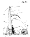
- FIG. 29 is a side elevation view of a coiled tubing injector and reel according to FIG. 28, the injector being stored in a shipping position on its coiled tubing trailer;
- FIG. 30 a is a side elevation view of the sectional tubing trailer, with the mast erected, and with the crown positioned for drilling with a kelly, swivel and sectional tubing;
- FIG. 30 b is an end elevation view of the mast of FIG. 30 a , with the crown shifted for drilling with the kelly aligned with the wellbore;
- FIG. 31 a is a side elevation view of the mast with the crown shifted for installing the linear injector and initiating feeding of the coiled tubing;
- FIG. 31 b is an end elevation view of the mast of FIG. 31 a , with the crown positioned with the elevators set aside;
- FIG. 32 is a close up side view of a compact linear injector, ideal for implementation in hybrid arrangements described herein;
- FIG. 33 a is a side elevation view of the mast with the crown shifted for landing the linear injector positioned in the mast and with coiled tubing poised to rest in the guide arch;
- FIG. 33 b is an end elevation view of the mast of FIG. 33 a , with the crown positioned for manipulating the linear injector;
- FIG. 34 is a side elevation view of the mast of FIG. 33 a with the linear injector lowered and pinned in the mast for coiled tubing drilling;
- FIG. 35 a is a side elevation view of the mast with the crown shifted for setting the linear injector aside and for aligning the elevators for running in tubing or casing;
- FIG. 35 b is an end elevation view of the mast of FIG. 35 a , with the crown shifted so that the elevators are aligned for running tubing or casing.
- FIGS. 1-10 illustrate a particularly compact embodiment of an injector 100 .
- FIGS. 16-18 illustrate a second injector embodiment 200 , the variance between the two being characterized primarily in the packaging of the drives, the overall length of the coiled tubing gripping section, and the type of tubing holddowns.
- FIGS. 20-25 illustrate details of the gripper blocks common to both embodiments 100 , 200 .
- the novel concepts are common between the two preferred embodiments described herein.
- a new coiled tubing injector 100 is provided which is characterized by a linearly extending section 101 .
- This “linear” injector 100 in combination with a suitable support or mast (FIG. 12 , 27 ) can provide superior pulling capability, is gentle to coiled tubing and can also handle full diameter tubing, providing substantially all the advantages of both conventional sectional drill tubing and coiled tubing.
- the linear injectors 100 , 200 respectively comprise a continuous chain conveyor 102 fitted to a frame 109 having a chain 103 extending endlessly therearound.
- the continuous conveyor 102 is fitted with upper and lower drive sprockets 104 , 105 .
- the endless chain 103 is fitted with a multiplicity of coiled tubing gripper blocks 106 ; one block 106 per link of the chain 103 .
- the blocks 106 move with the chain conveyor 102 .
- the blocks 106 are pivotally interconnected with pins 107 which engage the upper and lower drive sprockets 104 , 105 .
- the moving gripper blocks 106 are formed with grooves 108 for accepting coiled tubing 110 .
- one portion of the continuous conveyor 102 forms the linear section 101 .
- a linear array 111 of complementary hold-down rollers 112 exert a normal force on the coiled tubing 110 , urging it into the moving gripper blocks 106 and thereby frictionally engaging the coiled tubing 110 with minimal damage caused thereto.
- the relatively long length of the linear section 101 combined with a uniform coiled tubing gripping force, imposes large pulling force on the coiled tubing 110 , resulting in significant pulling capability.
- the capability of the linear injector 100 is even further expanded to include the injection and pulling out large bore coiled tubing 110 in deep well drilling operations.
- the linear array 111 of hold-down rollers 112 comprises a multiplicity of these rollers 112 , distributed along, parallel to and facing the linear section 101 of gripper blocks 106 .
- the rollers 112 have corresponding grooves 113 to accept the coiled tubing 110 .
- a corridor 114 is formed between the opposing grooves 108 , 113 of the gripper blocks 106 and rollers 112 .
- the coiled tubing 110 extends through the corridor 114 .
- the moving gripper blocks 106 are movably supported by skate or track means 120 , located along the linear section 101 , so as to resist the reaction force produced by the rollers 112 and thereby grip the coiled tubing 110 extending in the corridor 114 therebetween.
- first and second block embodiments shown in FIGS. 1-6, 20 - 25 respectively, the moving gripper blocks 106 themselves (roller gripper blocks 106 a ) form the continuous chain conveyor 102 . This is in contrast to the independent assembly 106 b of blocks 106 and chain 103 illustrated in a third embodiment shown in FIGS. 19 a - 19 c.
- each roller gripper block 106 a comprises a block 106 formed with a semi-circular groove 108 , fitted with a replaceable insert 121 which is sized to match the diameter of the coiled tubing 110 being used.
- the insert can have a tungsten carbide surface finish (not visible) placed thereon for increased longevity and gripping (friction) capability.
- the roller gripper blocks 106 a have an offset link configuration having narrow first bifurcated prongs 122 and second wider bifurcated prongs 123 . Adjacent roller gripper blocks 106 a , 106 a interconnect with the first prongs 122 fitting between the wider second prongs 123 of the immediately adjacent roller block 106 a with pin 107 pivotally connecting them together.
- roller blocks 116 themselves form the continuous chain conveyor 102 and are fitted with the grooves 108 and inserts 121 .
- two types of roller blocks 116 are provided; one block 116 a having closely spaced links 117 a and another block 116 b with widely spaced links 117 b .
- Each roller block 116 a , 116 b is mounted to (or formed with) a pair of parallel links 117 a , 117 b , spaced sufficiently to enable the upper and lower sprockets 104 , 105 to pass therebetween (FIG. 25 ).
- the roller pin 107 passes transversely through the links 117 a , 117 b for pivotally pinning them together.
- the narrow spaced links 117 a fit between the widely spaced links 17 b , the narrow and widely spaced link roller blocks 116 a , 116 b connected in alternating fashion and, when pinned together, form the continuous chain conveyor 102 , shown wrapped about a sprocket 104 , 105 .
- the interconnecting pins 107 of any block 106 or specific configuration 106 a , 116 a , 116 b are engaged by the upper and lower drive sprockets 104 , 105 .
- the transverse or distal end of each pin 107 supports an idler assembly 122 having a bearing 123 and idler 124 which engages a backing track 120 , enabling the blocks 106 to resist the normal force imposed by the rollers 112 .
- the backing track 120 is conveniently formed by flat bar atop parallel “I”-beams 123 forming the structure or frame 109 of the linear injector 100 .
- separate gripper blocks 106 c are provided as a separate component mounted to brackets 130 on roller chain 131 .
- the continuous conveyor 102 can be supported along its linear section 101 by a linear skate 132 , backing the roller chain 131 .
- the chain conveyor 102 is driven at one or both of the upper and lower sprockets 104 , 105 preferably with primer movers 133 such as hydraulic motors or planetary drives.
- primer movers 133 such as hydraulic motors or planetary drives.
- the path of the continuous chain conveyor 102 forms a periphery about an interior 134 .
- Efficient use of the interior 134 results in a compact and narrow arrangement wherein four prime movers 133 are nested within the injector interior 134 , using belted or chain transmission 135 coupled to sprockets 136 to drive the conveyor 102 .
- a direct planetary drive 137 is shown coupled and extending laterally and directly off the sprocket.
- the prime movers 133 are reversible for providing injection force in one rotational direction and pulling force in the other rotational direction.
- the pitch of the conveyor chain 102 is minimized to reduce the diameter of the upper and lower sprockets 104 , 105 , resulting in a reduced driving moment and reduced drive size.
- biasing means are provided for urging holddown rollers 112 into engagement with the coiled tubing 110 .
- First and second telescoping members 140 , 141 extend between the rollers 112 and the track 118 or frame 109 .
- Spring means 142 (FIG. 10) are placed between first and second members 140 , 141 for maintaining compression on the coiled tubing 110 .
- a lateral and levered arrangement of complementary pairs of fixed and adjustable struts 143 , 144 urge holddown rollers 112 towards the gripper blocks 106 for sandwiching the coiled tubing 110 therebetween.
- the adjustable struts 144 form the spring means 142 and telescoping members 140 , 141 .
- a plurality of these lever arrangements are provided in the array 111 along the injector's linear section 101 .
- each strut 144 comprises a cylindrical housing 145 (of the first telescoping member 140 ), a shaft 146 (the second telescoping member 141 ) and conical spring or load-indicating washers 142 .
- the strut 144 can only be pulled from the housing 145 by compression of the washers 142 .
- the struts 144 set the appropriate load for maximizing normal force on the roller 112 without damaging the coiled tubing 110 .
- Other elastomeric load-indicating washers may also be used.
- the complementary fixed struts 143 provide the fulcrum from which the rollers 112 are levered into engagement with the coiled tubing 110 . Further, the fixed struts 143 incorporated a coarse threaded adjustment 146 for setting the position of the holddown rollers 112 .
- the holddown rollers 112 themselves are provided in parallel pairs, rotatably fitted to a rocker housing 150 .
- the rocker housing 150 has a single pivot shaft 151 which is secured at each end to the fixed and adjustable struts 143 , 144 .
- the pivot and rocker housing 151 , 150 ensures that load is distributed between the two parallel rollers 112 .
- the force produced by the roller 112 can be dynamically adjusted using hydraulic actuators 147 , further enabling the rollers 112 to adjust the normal gripping force or optionally to temporarily and sequentially lift the rollers 112 off the coiled tubing 110 or sectional tubing to pass an upset or other diameter variation.
- the long linear section 101 can also accommodate long rigid sectional strings (not shown).
- the linear injector 100 , 200 can be used in a variety of heretofore restricted applications including the injection of long strings of downhole tools or in the case of drilling operations, injecting and pulling out large bore coiled tubing 110 in deep well drilling operations.
- rollers 112 can be grouped intoarrays 149 (FIG. 17 ), each having several rollers 112 (e.g. five) minimizing the number of hydraulic actuators 147 .
- a tubing straightener 160 is located at the upper end 41 of the linear injector 100 , 200 so that coiled tubing 110 , without appreciable residual bend, is caused to enter the injector, reducing load on the gripper blocks 106 and rollers 112 and further so that coiled tubing 110 leaves the linear injector 100 , 200 straight.
- the straightener 160 re-bends the tubing 110 to the lowest stress possible unsupported shape—preferably a parabolic shape.
- FIG. 11 four gripper blocks 106 and corresponding holddown rollers 112 were constructed according to FIGS. 7 and 8 and in opposed relation to form the corridor 114 .
- the gripper blocks 106 were anchored to a base structure 164 so as to be immovable.
- a length of tubing 110 was installed in the corridor 114 and affixed to a first hydraulic pull cylinder 165 .
- a second hydraulic normal-force cylinder 166 forces the hold down rollers 112 into engagement with the length of tubing 110 . Any movement of the tubing 110 , indicating slippage of the tubing 110 in the gripper blocks 106 , was measured by a dial indicator (not shown).
- the first pull cylinder 165 had a 12.5 in 2 effective area or 1,250 lbs. of pull force per 100 lbs. hydraulic pressure.
- the second normal force cylinder 166 had a 5.15 in 2 effective area capable of producing a total normal force of 20,600 lbs. at a pressure of 4000 psi. For four rollers, this became 5,150 lbs. per roller.
- the four gripper block inserts 121 (not detailed) were sprayed with a friction enhancing tungsten carbide coating.
- the pressure of the first pull cylinder 165 was increased until slippage occurred. Slippage occurred consistently at about 1000 psi. Accordingly, the pull force was about 12,500 lbs or each of the four gripper blocks 106 were holding up to 12,500/4 or 3,125 lbs. each. With the imposed normal force of 5,150 lbs. each, the coefficient of friction at slip was about 3,125/5,150 or 0.61. Assuming an efficiency of 80% to account for drive and friction losses in a full injector 100 , 200 , the effective coefficient of friction is only 0.5 (0.61*0.80).
- the linear injector 100 , 200 is particularly suited to use in combination with one or more arrangements of apparatus for conventional sectional drilling.
- a conventional mast is implemented constructed in a style in common use today .
- a coiled tubing linear injector is arranged for installation and access through the same V-door as is used for handing conventional sectional tubing. Simply, in this arrangement, all drilling activity is performed through the same mast access.
- a portable, dual duty mast which enables access from two sides. Accordingly, a coiled tubing injector can be arranged for access from one open side and sectional tubing from the second open side.
- mast capable of handling stands of 2 or 3 lengths of tubing. This requires a mast of 130-140 feet in height.
- a mast of only about 75 feet in height is required—set only by the length of tubulars being handled, the usual constraint being “Range-3”, 45 ft. long casing.
- coiled tubing has only a cumulative weight of about 7 lbs./ft. compared to about 16 lbs./ft. with the associated sectional tubing having heavy collars and thicker walls.
- a conventional, sectional tubing, drilling rig (conventional rig) 201 is positioned at a well 202 .
- the well is fitted with a Blow-out Preventor (BOP) 202 b .
- BOP Blow-out Preventor
- a novel, coiled tubing transport rig 203 (CT Rig) is also positioned at the well 202 .
- CT Rig novel, coiled tubing transport rig 203
- the preferred CT Rig 203 incorporates only means for transporting the novel injector 200 and does not include pumps and the like, and thus is substantially less complicated and less expensive than prior art coiled tubing injector rigs.
- the CT Rig 203 comprises a mobile trailer or truck frame 205 having a coiled tubing spool 206 mounted thereon.
- Conventional means (not detailed) are provided for managing coiled tubing dispensing and retrieving, including spool drives.
- a curved feed arch 207 assists in directing the coiled tubing 110 approximately along a parabolic loop 208 .
- the parabolic loop 208 has been found to be a low stress configuration for the loop of coiled tubing.
- the CT Rig 203 forms a transport bed 208 for storing and transporting the linear injector 200 to the well 202 .
- the transport rig 203 is mounted and supported in the mast 204 of the conventional rig 201 .
- the conventional rig 201 may comprise a mobile trailer 210 , the mast 204 rising from substructure and a rotary table 211 , at the drilling floor 212 , to draw works 213 in the crown 214 and means for suspending the linear injector 200 in the mast 204 .
- the upper end 215 of the continuous conveyor 200 is fitted with second guide arch or gooseneck 216 for guiding the coiled tubing 110 .
- the CT Rig 203 and conventional rig 201 are oriented out of alignment for retaining full functionality of the conventional rig 201 . Accordingly, a catwalk 217 and pipe rack 218 are able to access the drilling floor 212 . Further, mud pumps 218 and mud tanks 219 accompany the conventional rig 201 .
- the linear injector 200 is a continuous conveyor 102 having an upper 215 and a lower end 225 . As shown in FIGS. 28 and 29, the lower end 215 of the linear injector 200 is rotationally pinned in the mast 204 above the drilling floor 212 . The linear injector 200 is hoisted into the mast 204 . As shown in FIG. 15, a cable 220 from the mast's draw works 213 is directed about an idler 221 located about the monkeyboard and is attached to the upper end 215 of the linear injector 200 .
- the upper end 215 is hoisted upwardly, pivoting the linear injector 200 about the bottom end 225 and into position.
- the linear injector 200 is aligned with the BOP 202 b .
- the linear injector 200 is secured for suspending it in the mast 204 .
- the linear injector 200 can be alternated between two positions within the mast 204 . In a first position, the injector is aligned with the BOP 202 b for injection and withdrawal of coiled tubing 110 . In a second position, the linear injector 200 is shifted or set aside in the mast 204 to take the injector out of alignment from the BOP 202 b . When out of alignment, the mast 204 can be used in a conventional manner; more specifically to enable sectional tubulars to be pulled up the catwalk 217 and into the mast 204 and utilizing the rotary table 213 for making up the tubular's threaded joints.
- a high capacity draw works 213 and a rotary table 211 are now available.
- the physical distance placed between the conventional rig 201 and the source of the coiled tubing (the spool 206 ) enables the formation of a large radius parabolic loop 208 further allowing the injector rig to utilize large coiled tubing diameters, including 3.5 inch diameter typical for use in conventional rigs.
- the long linear injector 200 is capable of dealing with large lengths of coiled or sectional tubing.
- use of the large fluid bore of 3.5 inch tubing 110 reduces fluid friction pumping power requirements from about 1000 HP to only 5-600 HP at 5,000 feet. It is postulated that a 5,000 foot deep well can be drilled in about 1 ⁇ 2 the time conventionally required due to the elimination of the need to make up joints every 30 feet.
- the length of the linear section 101 is configurable depending upon the driving force required. Maximum length would be limited by the working height within the mast 204 . For instance for a working height of about 50-60 feet, normally provided for making up stands of sectional tubulars, the linear section 101 of the injector 200 could be upwards of 30 feet tall.
- the straightener 160 and a coiled tubing guide gooseneck must also be accommodated in the mast 204 .
- BHA Bottom Hole Assemblies
- a BHA includes the bit, mud motor and measurement equipment, which must be made up and can be in the order of 30 feet in length.
- Conventional coiled tubing drilling units have tried various means to make up the BHA, requiring the various pieces to be threaded together. This is usually a labor intensive job because coiled tubing units are not normally set up to rotate tubing to make up the joints. Occasionally drill collars are also threaded onto the BHA to provide startup drilling weight or improve linear stability.
- a conventional mast 204 with the linear injector 100 , 200 , the capital costs of the whole operation are reduced.
- a rig transporting a linear injector 100 , 200 need not have a mast, nor fluid pumping equipment and can simply include the coiled tubing injector 200 and spool 206
- the conventional mast 204 provides the capability of lifting at the required high pull forces and through the use of the rotary table 31 enables readily making up BHA and connections onto the non rotating coiled tubing 11 .
- the linear injector 200 is particularly well suited for shallow directional drilling or the insertion of downhole tools such as pumps or for workovers, and is able to provide continuous, straightened tubing into any well, including a slant wellhead and BOP 202 b .
- the linear injector 200 can be located on its own trailer 203 and does not require further mast superstructure.
- the linear injector 200 can be transported prone (stage (a)), raised partially for injection through a slant wellhead/BOP 202 b (stage (b)) or raised completely for injection down a vertical well (stage (c)).
- a BHA for directional drilling or a pump can be pre-assembled and carried on an integrated coiled tubing injector rig for injection without additional equipment.
- a first rig 301 comprises a collapsible mast 304 on a first trailer, a substructure, rotary tubing drive means 311 (table or power swivel), side shifting crown 314 , dual blocks 313 a and dual drawworks 313 .
- drawworks 313 b is also used to describe the winches 131 d , cable 313 e , crown pulley 313 b and blocks 313 a in combination.
- drawworks 313 includes means for attaching various tools, such as a hook 313 c for handing elevators, swivels and the injector 100 .
- An integrated hydraulic system powers the drawworks 313 , side-shifting crown 313 b , rotary table 311 and lifts the collapsible mast 304 .
- a second rig 303 comprises a coiled tubing injector and a reel of coiled tubing on a second trailer.
- Suitable support equipment is provided such as a mud system, mud pump and control house.
- the first rig 301 is transported to a well in a transportable, collapsed form.
- the substructure 350 is located at the trailer's back end 351 .
- the substructure 350 is optionally equipped with a wellhead and BOP 302 b for centering over the well 302 .
- the rotary table 311 is installed in the substructure 350 for positioning over the center of the BOP 302 b .
- the mast 304 has its crown 353 and a base 354 formed of two support structures 355 , 356 pivotally connected at the crown 353 and having a transverse dimension about that of the width of the trailer 305 .
- the two support structures 355 , 356 lie substantially parallel to the trailer 305 , arranged as one lower support structure 355 and one upper support structure 356 .
- the clearances of the top of the substructure 350 and the top of the upper support structure 356 are both optimally low enough for highway travel.
- the lower support structure is pivotally connected at its base 355 b to the substructure 350 .
- the base 356 b of the upper support is free for subs frequent pinning at 356 c when erect.
- Hydraulic rams 357 are located between the mast's lower support structure 355 and the trailer 305 and, when energized, drive the mast 304 into the erect position.
- the coiled tubing injector 100 is positioned at the second rig's back end 370 .
- a coiled tubing supply reel 306 is positioned mid-tailer and is capable of storing up to 6500 feet of 31 ⁇ 2 inch tubing, 8500 feet of 27 ⁇ 8′′ tubing or 12,000 feet of 23 ⁇ 8′′ tubing.
- each of the lower and upper support structures 355 , 356 are designed to support the compressive loads of pulling tubing without the requirement for significant cross bracing.
- each of the lower and upper support structures 355 , 356 are formed of a pair of spaced legs 371 constructed of hollow structural tubing depending downwardly from the crown 353 . Between the legs 371 is formed a large open side 372 , suitable for tubing access.
- the crown 353 comprises a horizontal beam 373 and ties the two pairs of legs 371 together.
- the crown 353 when erected, the crown 353 is positioned over the well 302 .
- the trailer 305 itself forms a catwalk 317 for handling conventional sectional tubing or tubulars 310 .
- the crown 353 is shown equipped with a shifting crown 313 b comprising a first block 381 and second block 382 movable laterally in the crown 353 .
- the first and second blocks 381 , 382 are alternately positionable one or the other over the well 302 .
- Each block 381 , 382 has means, such as a hook 313 c , for attaching various tools.
- the second block 382 is shown, fitted with a hook 313 c , a swivel 383 and a kelly 384 .
- the kelly 384 is driven by the rotary table 311 for drilling purposes.
- the first and second rigs 301 , 303 are arranged back end 351 to back end 371 .
- the mast 304 when erected, has a first side open 374 to the trailer 305 of the first rig 301 for forming a catwalk 317 for drill pipe, casing or tubulars 310 generally.
- the opposing side of the mast 304 is open to the second coiled tubing rig 303 . Accordingly, lengths of sectional tubulars 310 can be handled or drawn up the first open side 374 from the first rig 301 ; and coiled tubing 110 can be introduced from the second open side 375 .
- the coiled tubing rig 303 is not necessarily provided with a guide arch.
- a guide arch 316 is instead pivotally connected to and shipped with the mast 304 .
- the guide arch 316 is pivoted out from the upper support structure 356 so that it projects laterally therefrom.
- the coiled tubing injector 100 is released from its shipping condition.
- One of the blocks 382 (the second block being shown) is lowered to capture the injector 100 for lifting it into the mast 304 .
- the coiled tubing 110 is spooled off of the reel 306 .
- An objective is to maintain a gentle loop, such as a parabolic shaped loop 308 , for minimizing stress in the coiled tubing 110 .
- Cables 385 stabilize the injector 100 as i t is lifted and prevent it from colliding with the mast 304 .
- the injector 100 is hung in the mast 304 and the coiled tubing 110 is aligned over t he guide arch 316 .
- the injector 1100 is landed on the substructure 350 .
- a chair structure 390 at the bottom of the injector 100 couples with a corresponding base structure 391 on the substructure floor 312 .
- the chair 390 and base structure 391 telescope to permit several feet of vertical movement by the injector 100 but constrain the injector 100 aligned over the BOP 302 b and well 302 .
- the weight of the injector 100 and the coiled tubing 110 is borne by the drawworks 313 .
- the coiled tubing 110 is set into the guide arch 316 .
- the optimal curve in the coiled tubing is known as a parabolic loop 308 .
- a level wind 392 is provided for stabilizing the coiled tubing 110 as it traverses across the reel 306 as it spools on and off.
- the coiled tubing injector 100 can be of any design which is capable of fitting in the mast 100 with enough spare lateral room to permit the injector 100 to be shifted out of the way and to permit the other block 381 , 382 to be aligned with the well 302 .
- the linear coiled tubing injector 100 as described above meets such criteria.
- the depth of the injector 100 can be a narrow as three feet, and when idle, can be set aside in the mast 304 , such as when handling tubulars 310 (drill tubing or casing).
- Drilling with coiled tubing 110 is now possible with the injector 100 being operated as described above.
- the dual drawworks 381 , 382 are optimized to perform simultaneous operations and, as much as possible, minimize serial handling. For example, rather than utilizing a rotary table 311 and kelly 384 to both drill, then serially handle the next length of drill tubing 310 , the first block and drawworks 381 could be lifting the sequential tubular 310 while the previous tubular is being run in with the second block and drawworks 382 .
- optimal modes for drilling may vary from site to site.
- the hybrid apparatus is particularly versatile for adapting to the individual cases.
- drilling from surface in one instance may be best performed using conventional rotary drilling with a bit, drill collars and sectional tubing 310 .
- surface hole can be drilled with the coiled tubing injector 100 .
- surface hole is drilled and cased using threaded sectional tubulars and the remainder of the drilling is conducted with coiled tubing 110 .
- Drill surface hole Once drilled, run surface casing tubulars and install a wellhead/BOP 302 b.
- the first drawworks 381 can be side shifted in the crown 353 to clear the mast 304 over the well 302 .
- the second drawworks 383 are shifted and the injector 100 is set aside in the mast 304 .
- the first drawworks 381 could be fitted with elevators or with a swivel and kelly again for handling tubulars 310 .
Landscapes
- Engineering & Computer Science (AREA)
- Life Sciences & Earth Sciences (AREA)
- Geology (AREA)
- Mining & Mineral Resources (AREA)
- Mechanical Engineering (AREA)
- Physics & Mathematics (AREA)
- Environmental & Geological Engineering (AREA)
- Fluid Mechanics (AREA)
- General Life Sciences & Earth Sciences (AREA)
- Geochemistry & Mineralogy (AREA)
- Earth Drilling (AREA)
- Guides For Winding Or Rewinding, Or Guides For Filamentary Materials (AREA)
Abstract
Description
Claims (26)
Priority Applications (7)
| Application Number | Priority Date | Filing Date | Title |
|---|---|---|---|
| CA002298089A CA2298089A1 (en) | 2000-02-03 | 2000-02-03 | Linear coiled tubing injector |
| US09/569,965 US6332501B1 (en) | 2000-02-03 | 2000-05-12 | Linear coiled tubing injector |
| CA002332290A CA2332290C (en) | 2000-02-03 | 2001-01-26 | Hybrid sectional and coiled tubing drilling rig |
| CA002332420A CA2332420C (en) | 2000-02-03 | 2001-01-26 | Linear coiled tubing injector |
| PCT/CA2001/000105 WO2001057355A1 (en) | 2000-02-03 | 2001-01-29 | Linear coiled tubing injector/hybrid sectional and coiled tubing drilling rig |
| AU2001229928A AU2001229928A1 (en) | 2000-02-03 | 2001-01-29 | Linear coiled tubing injector/hybrid sectional and coiled tubing drilling rig |
| US09/815,623 US6408955B2 (en) | 2000-02-03 | 2001-03-23 | Hybrid sectional and coiled tubing drilling rig |
Applications Claiming Priority (3)
| Application Number | Priority Date | Filing Date | Title |
|---|---|---|---|
| CA002298089A CA2298089A1 (en) | 2000-02-03 | 2000-02-03 | Linear coiled tubing injector |
| CA2298098 | 2000-02-03 | ||
| US09/569,965 US6332501B1 (en) | 2000-02-03 | 2000-05-12 | Linear coiled tubing injector |
Related Child Applications (1)
| Application Number | Title | Priority Date | Filing Date |
|---|---|---|---|
| US09/815,623 Division US6408955B2 (en) | 2000-02-03 | 2001-03-23 | Hybrid sectional and coiled tubing drilling rig |
Publications (1)
| Publication Number | Publication Date |
|---|---|
| US6332501B1 true US6332501B1 (en) | 2001-12-25 |
Family
ID=25681518
Family Applications (2)
| Application Number | Title | Priority Date | Filing Date |
|---|---|---|---|
| US09/569,965 Expired - Lifetime US6332501B1 (en) | 2000-02-03 | 2000-05-12 | Linear coiled tubing injector |
| US09/815,623 Expired - Fee Related US6408955B2 (en) | 2000-02-03 | 2001-03-23 | Hybrid sectional and coiled tubing drilling rig |
Family Applications After (1)
| Application Number | Title | Priority Date | Filing Date |
|---|---|---|---|
| US09/815,623 Expired - Fee Related US6408955B2 (en) | 2000-02-03 | 2001-03-23 | Hybrid sectional and coiled tubing drilling rig |
Country Status (4)
| Country | Link |
|---|---|
| US (2) | US6332501B1 (en) |
| AU (1) | AU2001229928A1 (en) |
| CA (3) | CA2298089A1 (en) |
| WO (1) | WO2001057355A1 (en) |
Cited By (26)
| Publication number | Priority date | Publication date | Assignee | Title |
|---|---|---|---|---|
| US20030034162A1 (en) * | 2001-07-03 | 2003-02-20 | Emanuel Kulhanek | Well string injection system and method |
| US6530432B2 (en) * | 2001-07-11 | 2003-03-11 | Coiled Tubing Solutions, Inc. | Oil well tubing injection system and method |
| US6609566B2 (en) * | 1999-01-15 | 2003-08-26 | Drilling & Coiled Technology, Inc., A Division Of Gotco International, Inc. | Gripper block assembly for coiled tubing injector head |
| US20040118556A1 (en) * | 2002-12-19 | 2004-06-24 | Widney Mark D. | Guide support for rig mounted continuous feed injection unit |
| US20040118573A1 (en) * | 2002-12-19 | 2004-06-24 | Jason Schroeder | Well string injection system with gripper pads |
| US6973979B2 (en) | 2003-04-15 | 2005-12-13 | Savanna Energy Services Corp. | Drilling rig apparatus and downhole tool assembly system and method |
| US20060260844A1 (en) * | 2005-05-19 | 2006-11-23 | Patton Bartley J | Coiled tubing drilling rig |
| US20060266528A1 (en) * | 2005-05-26 | 2006-11-30 | Emanuel Kulhanek | Balanced continuous well string injection unit |
| US20060283588A1 (en) * | 2005-06-17 | 2006-12-21 | Wood Thomas D | System, method and apparatus conducting earth borehole operations |
| US20060283587A1 (en) * | 2005-06-17 | 2006-12-21 | Wood Thomas D | System, method and apparatus for conducting earth borehole operations |
| US20070125551A1 (en) * | 2005-12-05 | 2007-06-07 | Richard Havinga | Method and apparatus for conducting earth borehole operations |
| US20080023227A1 (en) * | 2006-07-25 | 2008-01-31 | Bartley Patton | Coiled tubing and drilling system |
| US7549468B2 (en) | 2005-12-13 | 2009-06-23 | Foremost Industries Ltd. | Coiled tubing injector system |
| US20090250205A1 (en) * | 2005-03-30 | 2009-10-08 | Sietse Jelle Koopmans | Coiled Tubing Injector Head |
| US20100132935A1 (en) * | 2008-10-27 | 2010-06-03 | David Brian Magnus | Gripper Block |
| CN102704870A (en) * | 2012-04-19 | 2012-10-03 | 烟台杰瑞石油服务集团股份有限公司 | Coiled tubing clamping device and injection head using same |
| US8544536B2 (en) | 2010-09-24 | 2013-10-01 | National Oilwell Varco, L.P. | Coiled tubing injector with limited slip chains |
| US8701754B2 (en) | 2012-06-18 | 2014-04-22 | National Oilwell Varco, L.P. | Coiled tubing injector with strain relief |
| AU2010328737B2 (en) * | 2009-12-07 | 2014-10-23 | Annulus Intervention System AS | Injection module, method and use for lateral insertion and bending of a coiled tubing via a side opening in a well |
| WO2014182949A1 (en) * | 2013-05-09 | 2014-11-13 | Premier Coil Solutions | Chain service indicator |
| US9399895B2 (en) | 2011-09-02 | 2016-07-26 | National Oilwell Varco L.P. | Coiled tubing injector head with chain guides |
| US9428973B2 (en) | 2013-05-07 | 2016-08-30 | Premier Coil Solutions, Inc. | Quick-release gripping insert assembly |
| US20170121162A1 (en) * | 2015-11-03 | 2017-05-04 | Cameron International Corporation | Rope hoisting system |
| US9850713B2 (en) | 2015-09-28 | 2017-12-26 | Must Holding Llc | Systems using continuous pipe for deviated wellbore operations |
| WO2019162655A1 (en) * | 2018-02-22 | 2019-08-29 | Maats Tech Limited | Overboarding device |
| US11274505B2 (en) | 2020-02-21 | 2022-03-15 | Enquest Energy Solutions, Llc | Gripper assembly for a coiled tubing injector |
Families Citing this family (29)
| Publication number | Priority date | Publication date | Assignee | Title |
|---|---|---|---|---|
| CA2322917C (en) * | 2000-10-06 | 2007-01-09 | Cancoil Integrated Services Inc. | Trolley and traveling block system |
| US6554075B2 (en) * | 2000-12-15 | 2003-04-29 | Halliburton Energy Services, Inc. | CT drilling rig |
| US6672394B2 (en) * | 2001-06-19 | 2004-01-06 | Heartland Rigs International, Llc | Interchangeable coiled tubing support block and method of use |
| US7051818B2 (en) * | 2002-04-22 | 2006-05-30 | P.E.T. International, Inc. | Three in one combined power unit for nitrogen system, fluid system, and coiled tubing system |
| US20060048933A1 (en) * | 2004-09-07 | 2006-03-09 | John Van Way | Method and apparatus for spooled tubing operations |
| CA2501463A1 (en) * | 2005-03-17 | 2006-09-17 | Frac Source Inc. | Support apparatus for a lubricator in a coiled tubing operation |
| CA2629561C (en) * | 2005-11-17 | 2012-03-13 | Xtreme Coil Drilling Corp. | Integrated top drive and coiled tubing injector |
| US7401656B2 (en) * | 2005-12-05 | 2008-07-22 | Xtreme Coil Drilling Corp. | Mobile drilling rig with dual carriers |
| US8408288B2 (en) * | 2006-03-07 | 2013-04-02 | Xtreme Drilling And Coil Services Corp. | System for conducting jointed pipe and coiled tubing operations |
| EA014374B1 (en) * | 2006-03-15 | 2010-10-29 | Экстрим Койл Дриллинг Корп. | Mobile drilling rig and a method for selectively inserting coiled tubing or threaded tubulars into a well |
| WO2008134055A1 (en) * | 2007-04-29 | 2008-11-06 | Wise Well Intervention Services, Inc. | Modular well servicing unit |
| US7798237B2 (en) | 2007-05-07 | 2010-09-21 | Nabors Alaska Drilling, Inc. | Enclosed coiled tubing rig |
| CA2694581A1 (en) * | 2007-07-27 | 2009-02-05 | Expro Ax-S Technology Limited | Deployment system |
| GB0803231D0 (en) * | 2008-02-22 | 2008-04-02 | Qserv Ltd | Apparatus and method |
| US8672043B2 (en) | 2010-11-03 | 2014-03-18 | Nabors Alaska Drilling, Inc. | Enclosed coiled tubing boat and methods |
| US20120111581A1 (en) * | 2010-11-04 | 2012-05-10 | Schlumberger Technology Corporation | Apparatus and method for reducing the residual bending and fatigue in coiled tubing |
| CN104350230B (en) | 2012-03-01 | 2017-02-22 | 沙特阿拉伯石油公司 | continuous rotary drilling system and method of use |
| US9790751B2 (en) * | 2012-05-14 | 2017-10-17 | Nabors Drilling International Limited | Drilling rig employing top drive |
| US9410382B2 (en) | 2012-05-14 | 2016-08-09 | Nabors Drilling International Limited | Drilling rig carriage movable along racks and including pinions driven by electric motors |
| US9995094B2 (en) | 2014-03-10 | 2018-06-12 | Consolidated Rig Works L.P. | Powered milling clamp for drill pipe |
| WO2018132861A1 (en) | 2017-01-18 | 2018-07-26 | Deep Exploration Technologies Crc Limited | Mobile coiled tubing drilling apparatus |
| EP3421711B1 (en) | 2017-06-28 | 2020-04-29 | National Oilwell Varco Norway AS | Drilling system and method |
| US10787870B1 (en) | 2018-02-07 | 2020-09-29 | Consolidated Rig Works L.P. | Jointed pipe injector |
| CN109854184B (en) * | 2019-02-23 | 2024-09-17 | 中国石油大学(华东) | Dual derricks and casing handling system and method for submarine drilling rigs |
| RU197401U1 (en) * | 2019-12-05 | 2020-04-23 | Общество с ограниченной ответственностью "РГМ-Нефть-Газ-Сервис" | COIL TUBING FEED MECHANISM |
| CN111350459B (en) * | 2020-03-12 | 2021-07-27 | 中煤科工集团西安研究院有限公司 | Double-diesel-engine power vehicle-mounted drilling machine and control method thereof |
| CN112452627B (en) * | 2020-11-07 | 2022-04-26 | 欣润润滑科技(广东)有限公司 | Device is paintd with lubricating oil high efficiency to chain processing production |
| WO2022129246A1 (en) * | 2020-12-17 | 2022-06-23 | Itrec B.V. | Recirculating cylindrical rollers assembly for supporting a pile holding system on a rail |
| NL2028920B1 (en) * | 2021-08-04 | 2023-02-17 | Itrec Bv | Recirculating cylindrical rollers assembly for supporting an object on a rail, e.g. in a pile holding system |
Citations (21)
| Publication number | Priority date | Publication date | Assignee | Title |
|---|---|---|---|---|
| US2567009A (en) | 1948-06-24 | 1951-09-04 | Shell Dev | Equipment for inserting small flexible tubing into high-pressure wells |
| US3313346A (en) | 1964-12-24 | 1967-04-11 | Chevron Res | Continuous tubing well working system |
| US3363880A (en) | 1966-11-14 | 1968-01-16 | Schiumberger Technology Corp | Cable-feeding apparatus |
| US3373818A (en) | 1965-10-20 | 1968-03-19 | Brown Oil Tools | Apparatus for running pipe |
| US3379052A (en) | 1965-09-20 | 1968-04-23 | Earle A. Howard | Soil penetrometer |
| US3559905A (en) | 1968-01-09 | 1971-02-02 | Corod Mfg Ltd | roeder; Werner H. |
| US4585061A (en) * | 1983-10-18 | 1986-04-29 | Hydra-Rig Incorporated | Apparatus for inserting and withdrawing coiled tubing with respect to a well |
| US4673035A (en) | 1986-01-06 | 1987-06-16 | Gipson Thomas C | Method and apparatus for injection of tubing into wells |
| US5188174A (en) * | 1991-04-03 | 1993-02-23 | Stewart & Stevenson Services, Inc. | Apparatus for inserting and withdrawing coil tubing into a well |
| US5215151A (en) | 1991-09-26 | 1993-06-01 | Cudd Pressure Control, Inc. | Method and apparatus for drilling bore holes under pressure |
| US5279364A (en) | 1991-02-27 | 1994-01-18 | Canadian Fracmaster Ltd. | Guide arch for tubing |
| US5309990A (en) | 1991-07-26 | 1994-05-10 | Hydra-Rig, Incorporated | Coiled tubing injector |
| US5553668A (en) | 1995-07-28 | 1996-09-10 | Halliburton Company | Twin carriage tubing injector apparatus |
| US5566764A (en) * | 1995-06-16 | 1996-10-22 | Elliston; Tom | Improved coil tubing injector unit |
| US5839514A (en) | 1997-05-23 | 1998-11-24 | Fleet Cementers, Inc. | Method and apparatus for injection of tubing into wells |
| US5842530A (en) | 1995-11-03 | 1998-12-01 | Canadian Fracmaster Ltd. | Hybrid coiled tubing/conventional drilling unit |
| US5890534A (en) | 1995-03-10 | 1999-04-06 | Baker Hughes Incorporated | Variable injector |
| US5918671A (en) | 1997-10-31 | 1999-07-06 | Willard P. Bridges D/B/A Coiled Tubing Products | Skate roller bearing for coiled tubing |
| US5975203A (en) | 1998-02-25 | 1999-11-02 | Schlumberger Technology Corporation | Apparatus and method utilizing a coiled tubing injector for removing or inserting jointed pipe sections |
| US6173769B1 (en) * | 1998-04-30 | 2001-01-16 | Hydra Rig, Inc. | Universal carrier for grippers in a coiled tubing injector |
| US6189609B1 (en) * | 1998-09-23 | 2001-02-20 | Vita International, Inc. | Gripper block for manipulating coil tubing in a well |
Family Cites Families (13)
| Publication number | Priority date | Publication date | Assignee | Title |
|---|---|---|---|---|
| US2187392A (en) * | 1937-01-11 | 1940-01-16 | Alvin H Lane | Derrick |
| US2787342A (en) * | 1954-01-07 | 1957-04-02 | Moore Corp Lee C | Trailer mounted drilling rigs |
| US3516183A (en) * | 1967-02-02 | 1970-06-23 | Stanley Serota | Grab with adjustable guide mast |
| US3658298A (en) * | 1969-10-14 | 1972-04-25 | United States Steel Corp | Drilling rig with shiftable crown blocks |
| US4336840A (en) * | 1978-06-06 | 1982-06-29 | Hughes Tool Company | Double cylinder system |
| US4621403A (en) * | 1984-05-18 | 1986-11-11 | Hughes Tool Company | Apparatus and method for inserting coiled tubing |
| US5244046A (en) * | 1992-08-28 | 1993-09-14 | Otis Engineering Corporation | Coiled tubing drilling and service unit and method for oil and gas wells |
| US5738173A (en) * | 1995-03-10 | 1998-04-14 | Baker Hughes Incorporated | Universal pipe and tubing injection apparatus and method |
| NO301088B1 (en) * | 1995-04-06 | 1997-09-08 | Harald Strand | Device for insertion of coiled tubing |
| NO975344D0 (en) * | 1997-11-21 | 1997-11-21 | Mercur Subsea Products Asa | Device at well, especially at associated rig |
| US6003598A (en) * | 1998-01-02 | 1999-12-21 | Cancoil Technology Corporation | Mobile multi-function rig |
| US6158516A (en) * | 1998-12-02 | 2000-12-12 | Cudd Pressure Control, Inc. | Combined drilling apparatus and method |
| US6273188B1 (en) * | 1998-12-11 | 2001-08-14 | Schlumberger Technology Corporation | Trailer mounted coiled tubing rig |
-
2000
- 2000-02-03 CA CA002298089A patent/CA2298089A1/en not_active Abandoned
- 2000-05-12 US US09/569,965 patent/US6332501B1/en not_active Expired - Lifetime
-
2001
- 2001-01-26 CA CA002332420A patent/CA2332420C/en not_active Expired - Fee Related
- 2001-01-26 CA CA002332290A patent/CA2332290C/en not_active Expired - Fee Related
- 2001-01-29 WO PCT/CA2001/000105 patent/WO2001057355A1/en active Application Filing
- 2001-01-29 AU AU2001229928A patent/AU2001229928A1/en not_active Abandoned
- 2001-03-23 US US09/815,623 patent/US6408955B2/en not_active Expired - Fee Related
Patent Citations (22)
| Publication number | Priority date | Publication date | Assignee | Title |
|---|---|---|---|---|
| US2567009A (en) | 1948-06-24 | 1951-09-04 | Shell Dev | Equipment for inserting small flexible tubing into high-pressure wells |
| US3313346A (en) | 1964-12-24 | 1967-04-11 | Chevron Res | Continuous tubing well working system |
| US3379052A (en) | 1965-09-20 | 1968-04-23 | Earle A. Howard | Soil penetrometer |
| US3373818A (en) | 1965-10-20 | 1968-03-19 | Brown Oil Tools | Apparatus for running pipe |
| US3363880A (en) | 1966-11-14 | 1968-01-16 | Schiumberger Technology Corp | Cable-feeding apparatus |
| US3559905A (en) | 1968-01-09 | 1971-02-02 | Corod Mfg Ltd | roeder; Werner H. |
| US4585061A (en) * | 1983-10-18 | 1986-04-29 | Hydra-Rig Incorporated | Apparatus for inserting and withdrawing coiled tubing with respect to a well |
| US4673035A (en) | 1986-01-06 | 1987-06-16 | Gipson Thomas C | Method and apparatus for injection of tubing into wells |
| US4673035B1 (en) | 1986-01-06 | 1999-08-10 | Plains Energy Services Ltd | Method and apparatus for injection of tubing into wells |
| US5279364A (en) | 1991-02-27 | 1994-01-18 | Canadian Fracmaster Ltd. | Guide arch for tubing |
| US5188174A (en) * | 1991-04-03 | 1993-02-23 | Stewart & Stevenson Services, Inc. | Apparatus for inserting and withdrawing coil tubing into a well |
| US5309990A (en) | 1991-07-26 | 1994-05-10 | Hydra-Rig, Incorporated | Coiled tubing injector |
| US5215151A (en) | 1991-09-26 | 1993-06-01 | Cudd Pressure Control, Inc. | Method and apparatus for drilling bore holes under pressure |
| US5890534A (en) | 1995-03-10 | 1999-04-06 | Baker Hughes Incorporated | Variable injector |
| US5566764A (en) * | 1995-06-16 | 1996-10-22 | Elliston; Tom | Improved coil tubing injector unit |
| US5553668A (en) | 1995-07-28 | 1996-09-10 | Halliburton Company | Twin carriage tubing injector apparatus |
| US5842530A (en) | 1995-11-03 | 1998-12-01 | Canadian Fracmaster Ltd. | Hybrid coiled tubing/conventional drilling unit |
| US5839514A (en) | 1997-05-23 | 1998-11-24 | Fleet Cementers, Inc. | Method and apparatus for injection of tubing into wells |
| US5918671A (en) | 1997-10-31 | 1999-07-06 | Willard P. Bridges D/B/A Coiled Tubing Products | Skate roller bearing for coiled tubing |
| US5975203A (en) | 1998-02-25 | 1999-11-02 | Schlumberger Technology Corporation | Apparatus and method utilizing a coiled tubing injector for removing or inserting jointed pipe sections |
| US6173769B1 (en) * | 1998-04-30 | 2001-01-16 | Hydra Rig, Inc. | Universal carrier for grippers in a coiled tubing injector |
| US6189609B1 (en) * | 1998-09-23 | 2001-02-20 | Vita International, Inc. | Gripper block for manipulating coil tubing in a well |
Cited By (55)
| Publication number | Priority date | Publication date | Assignee | Title |
|---|---|---|---|---|
| US6609566B2 (en) * | 1999-01-15 | 2003-08-26 | Drilling & Coiled Technology, Inc., A Division Of Gotco International, Inc. | Gripper block assembly for coiled tubing injector head |
| US20060076148A1 (en) * | 2001-06-25 | 2006-04-13 | Emanuel Kulhanek | Well string injection system and method |
| US20040020658A1 (en) * | 2001-06-25 | 2004-02-05 | Emanuel Kulhanek | Well string injection system and method |
| US20080017388A1 (en) * | 2001-06-25 | 2008-01-24 | Emanuel Kulhanek | Well string injection system and method |
| US7032676B2 (en) * | 2001-06-25 | 2006-04-25 | C-Tech Energy Services, Inc. | Well string injection system and method |
| US7383879B2 (en) | 2001-06-25 | 2008-06-10 | C-Tech Oilwell Technologies Inc. | Well string injection system and method |
| US8056639B2 (en) | 2001-07-03 | 2011-11-15 | Emanuel Kulhanek | Well string injection system and method |
| US20030034162A1 (en) * | 2001-07-03 | 2003-02-20 | Emanuel Kulhanek | Well string injection system and method |
| US6530432B2 (en) * | 2001-07-11 | 2003-03-11 | Coiled Tubing Solutions, Inc. | Oil well tubing injection system and method |
| US20040118556A1 (en) * | 2002-12-19 | 2004-06-24 | Widney Mark D. | Guide support for rig mounted continuous feed injection unit |
| US20040118573A1 (en) * | 2002-12-19 | 2004-06-24 | Jason Schroeder | Well string injection system with gripper pads |
| US6880629B2 (en) | 2002-12-19 | 2005-04-19 | C-Tech Energy Services, Inc. | Well string injection system with gripper pads |
| US6880630B2 (en) | 2002-12-19 | 2005-04-19 | C-Tech Energy Services, Inc. | Guide support for rig mounted continuous feed injection unit |
| US7513312B2 (en) | 2003-04-15 | 2009-04-07 | Savanna Energy Services Corp. | Drilling rig apparatus and downhole tool assembly system and method |
| US6973979B2 (en) | 2003-04-15 | 2005-12-13 | Savanna Energy Services Corp. | Drilling rig apparatus and downhole tool assembly system and method |
| US20070144745A1 (en) * | 2003-04-15 | 2007-06-28 | Gene Carriere | Drilling rig apparatus and downhole tool assembly system and method |
| US20090250205A1 (en) * | 2005-03-30 | 2009-10-08 | Sietse Jelle Koopmans | Coiled Tubing Injector Head |
| US7857042B2 (en) * | 2005-03-30 | 2010-12-28 | Asep Holding B.V. | Coiled tubing injector head |
| US20060260844A1 (en) * | 2005-05-19 | 2006-11-23 | Patton Bartley J | Coiled tubing drilling rig |
| US7600585B2 (en) | 2005-05-19 | 2009-10-13 | Schlumberger Technology Corporation | Coiled tubing drilling rig |
| US7318482B2 (en) | 2005-05-26 | 2008-01-15 | C-Tech Oilwell Technologies Inc. | Balanced continuous well string injection unit |
| US20060266528A1 (en) * | 2005-05-26 | 2006-11-30 | Emanuel Kulhanek | Balanced continuous well string injection unit |
| US8074710B2 (en) | 2005-06-17 | 2011-12-13 | Wood Thomas D | System for conducting earth borehole operations |
| US20110036559A1 (en) * | 2005-06-17 | 2011-02-17 | Wood Thomas D | System, method and apparatus for conducting earth borehole operations |
| US8627896B2 (en) | 2005-06-17 | 2014-01-14 | Xtreme Drilling And Coil Services Corp. | System, method and apparatus for conducting earth borehole operations |
| US20060283588A1 (en) * | 2005-06-17 | 2006-12-21 | Wood Thomas D | System, method and apparatus conducting earth borehole operations |
| US20060283587A1 (en) * | 2005-06-17 | 2006-12-21 | Wood Thomas D | System, method and apparatus for conducting earth borehole operations |
| US7810554B2 (en) | 2005-06-17 | 2010-10-12 | Xtreme Coil Drilling Corp. | System, method and apparatus for conducting earth borehole operations |
| US8191637B2 (en) * | 2005-12-05 | 2012-06-05 | Xtreme Coil Drilling Corp. | Method and apparatus for conducting earth borehole operations |
| US20070125551A1 (en) * | 2005-12-05 | 2007-06-07 | Richard Havinga | Method and apparatus for conducting earth borehole operations |
| US7549468B2 (en) | 2005-12-13 | 2009-06-23 | Foremost Industries Ltd. | Coiled tubing injector system |
| US7640999B2 (en) | 2006-07-25 | 2010-01-05 | Schlumberger Technology Corporation | Coiled tubing and drilling system |
| US20080023227A1 (en) * | 2006-07-25 | 2008-01-31 | Bartley Patton | Coiled tubing and drilling system |
| US20100132935A1 (en) * | 2008-10-27 | 2010-06-03 | David Brian Magnus | Gripper Block |
| US8132617B2 (en) | 2008-10-27 | 2012-03-13 | David Brian Magnus | Gripper block |
| AU2010328737B2 (en) * | 2009-12-07 | 2014-10-23 | Annulus Intervention System AS | Injection module, method and use for lateral insertion and bending of a coiled tubing via a side opening in a well |
| US8544536B2 (en) | 2010-09-24 | 2013-10-01 | National Oilwell Varco, L.P. | Coiled tubing injector with limited slip chains |
| US9458682B2 (en) | 2010-09-24 | 2016-10-04 | National Oilwell Varco, L.P. | Coiled tubing injector with limited slip chains |
| US9151122B2 (en) | 2010-09-24 | 2015-10-06 | National Oilwell Varco, L.P. | Coiled tubing injector with limited slip chains |
| US9399895B2 (en) | 2011-09-02 | 2016-07-26 | National Oilwell Varco L.P. | Coiled tubing injector head with chain guides |
| CN102704870A (en) * | 2012-04-19 | 2012-10-03 | 烟台杰瑞石油服务集团股份有限公司 | Coiled tubing clamping device and injection head using same |
| CN102704870B (en) * | 2012-04-19 | 2014-05-07 | 烟台杰瑞石油服务集团股份有限公司 | Coiled tubing clamping device and injection head using same |
| US8701754B2 (en) | 2012-06-18 | 2014-04-22 | National Oilwell Varco, L.P. | Coiled tubing injector with strain relief |
| US9428973B2 (en) | 2013-05-07 | 2016-08-30 | Premier Coil Solutions, Inc. | Quick-release gripping insert assembly |
| WO2014182949A1 (en) * | 2013-05-09 | 2014-11-13 | Premier Coil Solutions | Chain service indicator |
| US9617807B2 (en) | 2013-05-09 | 2017-04-11 | Premier Coil Solutions, Inc. | Chain service indicator |
| US9850713B2 (en) | 2015-09-28 | 2017-12-26 | Must Holding Llc | Systems using continuous pipe for deviated wellbore operations |
| US10156096B2 (en) | 2015-09-28 | 2018-12-18 | Must Holdings Llc | Systems using continuous pipe for deviated wellbore operations |
| US10465444B2 (en) | 2015-09-28 | 2019-11-05 | Must Holding Llc | Systems using continuous pipe for deviated wellbore operations |
| US10954720B2 (en) | 2015-09-28 | 2021-03-23 | Must Holding Llc | Systems using continuous pipe for deviated wellbore operations |
| US11286720B2 (en) | 2015-09-28 | 2022-03-29 | Must Holding Llc | Systems using continuous pipe for deviated wellbore operations |
| US20170121162A1 (en) * | 2015-11-03 | 2017-05-04 | Cameron International Corporation | Rope hoisting system |
| US9790070B2 (en) * | 2015-11-03 | 2017-10-17 | Cameron International Corporation | Rope hoisting system |
| WO2019162655A1 (en) * | 2018-02-22 | 2019-08-29 | Maats Tech Limited | Overboarding device |
| US11274505B2 (en) | 2020-02-21 | 2022-03-15 | Enquest Energy Solutions, Llc | Gripper assembly for a coiled tubing injector |
Also Published As
| Publication number | Publication date |
|---|---|
| CA2332420C (en) | 2004-08-10 |
| CA2332290A1 (en) | 2001-08-03 |
| US6408955B2 (en) | 2002-06-25 |
| WO2001057355A8 (en) | 2001-11-08 |
| CA2332290C (en) | 2004-08-10 |
| WO2001057355A1 (en) | 2001-08-09 |
| CA2298089A1 (en) | 2001-08-03 |
| AU2001229928A1 (en) | 2001-08-14 |
| US20010015274A1 (en) | 2001-08-23 |
| CA2332420A1 (en) | 2001-08-03 |
Similar Documents
| Publication | Publication Date | Title |
|---|---|---|
| US6332501B1 (en) | Linear coiled tubing injector | |
| US7478677B2 (en) | Coiled tubing/top drive rig and method | |
| US5738173A (en) | Universal pipe and tubing injection apparatus and method | |
| US7828087B2 (en) | Rocket rig drilling apparatus | |
| US8327927B2 (en) | Apparatus and method for performing earth borehole operations | |
| US7513312B2 (en) | Drilling rig apparatus and downhole tool assembly system and method | |
| EP0777810B1 (en) | Portable top drive | |
| US4899832A (en) | Modular well drilling apparatus and methods | |
| US20030196791A1 (en) | Tubular handling apparatus and method | |
| CN104302866A (en) | Boom mounted coiled tubing guide and method for running coiled tubing | |
| MXPA03001424A (en) | Combined drilling apparatus and method. | |
| WO2007007204A2 (en) | Apparatus and method for performing earth borehole operations | |
| CA2425448C (en) | Drilling rig apparatus and downhole tool assembly system and method | |
| WO2007067356A2 (en) | Univeral rig with vertical stand for tubulars | |
| EA010676B1 (en) | Coiled tubing top drive rig and method for inserting coiled tubing into a well | |
| US20060231269A1 (en) | Apparatus and method for performing earth borehole operations | |
| US4492502A (en) | Technique for picking up and laying down pipe | |
| AU2007226221B2 (en) | Mobile drilling rig with dual carriers | |
| AU723903B2 (en) | Universal pipe and tubing injection apparatus and method |
Legal Events
| Date | Code | Title | Description |
|---|---|---|---|
| AS | Assignment |
Owner name: PLAINS ENERGY SERVICES LTD., CANADA Free format text: ASSIGNMENT OF ASSIGNORS INTEREST;ASSIGNOR:GIPSON, THOMAS C.;REEL/FRAME:010808/0237 Effective date: 20000511 |
|
| AS | Assignment |
Owner name: PRECISION DRILLING CORPORATION, CANADA Free format text: ASSIGNMENT OF ASSIGNORS INTEREST;ASSIGNOR:PLAINS ENERGY SERVICES LTD.;REEL/FRAME:012089/0443 Effective date: 20010608 |
|
| STCF | Information on status: patent grant |
Free format text: PATENTED CASE |
|
| FEPP | Fee payment procedure |
Free format text: PAYER NUMBER DE-ASSIGNED (ORIGINAL EVENT CODE: RMPN); ENTITY STATUS OF PATENT OWNER: LARGE ENTITY Free format text: PAYOR NUMBER ASSIGNED (ORIGINAL EVENT CODE: ASPN); ENTITY STATUS OF PATENT OWNER: LARGE ENTITY |
|
| FEPP | Fee payment procedure |
Free format text: PAT HOLDER NO LONGER CLAIMS SMALL ENTITY STATUS, ENTITY STATUS SET TO UNDISCOUNTED (ORIGINAL EVENT CODE: STOL); ENTITY STATUS OF PATENT OWNER: LARGE ENTITY |
|
| FPAY | Fee payment |
Year of fee payment: 4 |
|
| FEPP | Fee payment procedure |
Free format text: PAYOR NUMBER ASSIGNED (ORIGINAL EVENT CODE: ASPN); ENTITY STATUS OF PATENT OWNER: LARGE ENTITY Free format text: PAYER NUMBER DE-ASSIGNED (ORIGINAL EVENT CODE: RMPN); ENTITY STATUS OF PATENT OWNER: LARGE ENTITY |
|
| AS | Assignment |
Owner name: ROYAL BANK OF CANADA, CANADA Free format text: SECURITY AGREEMENT;ASSIGNOR:PRECISION DRILLING CORPORATION;REEL/FRAME:022034/0306 Effective date: 20081223 |
|
| FPAY | Fee payment |
Year of fee payment: 8 |
|
| AS | Assignment |
Owner name: PRECISION DRILLING CORPORATION, CANADA Free format text: RELEASE BY SECURED PARTY;ASSIGNOR:ROYAL BANK OF CANADA;REEL/FRAME:025411/0632 Effective date: 20101117 |
|
| FPAY | Fee payment |
Year of fee payment: 12 |