US6319458B1 - Pulverized coal injecting apparatus - Google Patents
Pulverized coal injecting apparatus Download PDFInfo
- Publication number
- US6319458B1 US6319458B1 US09/509,711 US50971100A US6319458B1 US 6319458 B1 US6319458 B1 US 6319458B1 US 50971100 A US50971100 A US 50971100A US 6319458 B1 US6319458 B1 US 6319458B1
- Authority
- US
- United States
- Prior art keywords
- pulverized coal
- inner pipe
- dimples
- injecting apparatus
- pipe
- Prior art date
- Legal status (The legal status is an assumption and is not a legal conclusion. Google has not performed a legal analysis and makes no representation as to the accuracy of the status listed.)
- Expired - Fee Related
Links
- 239000003245 coal Substances 0.000 title claims abstract description 89
- 239000012530 fluid Substances 0.000 claims abstract description 30
- QVGXLLKOCUKJST-UHFFFAOYSA-N atomic oxygen Chemical compound [O] QVGXLLKOCUKJST-UHFFFAOYSA-N 0.000 abstract description 39
- 239000001301 oxygen Substances 0.000 abstract description 39
- 229910052760 oxygen Inorganic materials 0.000 abstract description 39
- 238000002485 combustion reaction Methods 0.000 abstract description 37
- 239000000446 fuel Substances 0.000 abstract description 11
- 238000000034 method Methods 0.000 description 10
- 239000000571 coke Substances 0.000 description 6
- 230000002093 peripheral effect Effects 0.000 description 6
- 229910000805 Pig iron Inorganic materials 0.000 description 5
- 230000003247 decreasing effect Effects 0.000 description 5
- MYMOFIZGZYHOMD-UHFFFAOYSA-N Dioxygen Chemical compound O=O MYMOFIZGZYHOMD-UHFFFAOYSA-N 0.000 description 4
- 230000000694 effects Effects 0.000 description 4
- 238000004519 manufacturing process Methods 0.000 description 4
- 239000007789 gas Substances 0.000 description 3
- XEEYBQQBJWHFJM-UHFFFAOYSA-N Iron Chemical compound [Fe] XEEYBQQBJWHFJM-UHFFFAOYSA-N 0.000 description 2
- 206010001497 Agitation Diseases 0.000 description 1
- IJGRMHOSHXDMSA-UHFFFAOYSA-N Atomic nitrogen Chemical compound N#N IJGRMHOSHXDMSA-UHFFFAOYSA-N 0.000 description 1
- 230000002411 adverse Effects 0.000 description 1
- 238000013019 agitation Methods 0.000 description 1
- 238000005097 cold rolling Methods 0.000 description 1
- 238000007796 conventional method Methods 0.000 description 1
- 229910001873 dinitrogen Inorganic materials 0.000 description 1
- 229910001882 dioxygen Inorganic materials 0.000 description 1
- 239000010763 heavy fuel oil Substances 0.000 description 1
- 229910052742 iron Inorganic materials 0.000 description 1
- 239000007788 liquid Substances 0.000 description 1
- 239000000463 material Substances 0.000 description 1
- 230000035699 permeability Effects 0.000 description 1
- 239000002994 raw material Substances 0.000 description 1
- 239000002893 slag Substances 0.000 description 1
Images


Classifications
-
- C—CHEMISTRY; METALLURGY
- C21—METALLURGY OF IRON
- C21B—MANUFACTURE OF IRON OR STEEL
- C21B5/00—Making pig-iron in the blast furnace
- C21B5/001—Injecting additional fuel or reducing agents
- C21B5/003—Injection of pulverulent coal
Definitions
- the present invention relates to a pulverized coal injecting apparatus in which oxygen is used to improve the combustion of pulverized coal in a blast furnace using the pulverized coal instead of the expensive coal in a pig iron manufacturing process.
- the present invention relates to a pulverized coal injecting apparatus in which dimples are formed on the surface if an inner pipe to improve the combustion of the pulverized coal.
- FIG. 1 ( a ) Generally in a pig iron manufacturing process of a blast furnace, as shown in FIG. 1 ( a ), iron ore as a raw material and coke as a fuel are fed through the top of the furnace, while hot air is fed through a tuyere which is formed on a lower portion of the furnace. Thus, the coke is burned, thereby producing pig iron and slag.
- expensive coke is replaced with the pulverized coal by using a pulverized coal injecting apparatus 4 in which tuyere is formed to feed the pulverized coal.
- FIG. 1 ( b ) illustrates in detail the race way 3 .
- the unburnt pulverized coal passes through the coke layer within the blast furnace, to be partly discharged to the outside of the furnace, and to be partly accumulated within the coke layer in which the gas velocity is relatively slow.
- This accumulated unburnt pulverized coal remains within the inner region of the furnace to alter the gas flow. Further, it lowers the intra-furnace temperature, and increases the permeability resistance, with the result that the size of the race way is decreased.
- the pulverized coal feeding amount is increased, the decrease of the combustion efficiency of the pulverized coal becomes very serious, with the result that the manufacturing cost of the pig iron is increased.
- pure oxygen is enriched, thereby improving the combustion efficiency of the pulverized coal.
- the oxygen concentration in the hot air flow is increased so, as to promote the combustion of the pulverized coal.
- the flow amount of the hot blast is very large, and therefore, even if oxygen is enriched to a high degree, the actual oxygen concentration increases just by several percent, with the result that the final effect is meager. Further, the cost of newly building the oxygen producing facilities is very high, and therefore, there is a limit in carrying out the oxygen enrichment.
- FIG. 2 a illustrates one example of this.
- a pulverized coal injecting apparatus 10 is of a coaxial type, and the pulverized coal is fed through an inner pipe 12 , while pure oxygen is enriched in an outer pipe 11 .
- the oxygen concentration is raised to improve the combustion efficiency.
- the combustion efficiency is somewhat improved compared with the case of carrying out the hot blast oxygen enrichment.
- the external oxygen cannot intrude into the pulverized coal flow, but burns only in the outer regions.
- FIG. 2 b illustrates another effort of solving the above described problem.
- an oxygen flow swirler 23 is formed between the coaxial pipes, so as to form a vortex in the inner region of the pulverized coal flow.
- the effect of installing the swirler depends on how suitable it is to the structure of the burner. In other words, if the spiral angle is too deep, the oxygen is directed to the outside of the pulverized coal flow rather than the inner region, with the result that the combustion efficiency is lowered. On the other hand, if these angle is too shallow, it is not different from the case of the general coaxial lance as shown in FIG. 2 a.
- the oxygen feeding angle is altered to forcibly mix the oxygen into the pulverized coal flow.
- the combustion efficiency is improved, the flame width is expanded to cause damages in the tuyere.
- the leading end of the pipe is slightly protruded to alter the feeding angle, and therefore, the protrusion is worn out due to the continuous collisions with the pulverized coal flow.
- the present invention is intended to overcome the above described disadvantages of the conventional techniques.
- the pulverized coal injecting apparatus includes: a cylindrical inner pipe for feeding a pulverized coal into a tuyere; a cylindrical outer pipe coaxially surrounding the inner pipe; a spiral swirler formed on a surface of the inner pipe; the pulverized coal being supplied through the inner pipe; and a combustible fluid being supplied through between the outer and inner pipes.
- the pulverized coal injecting apparatus further includes: a plurality of dimples formed on the surface of the leading end portion of the inner pipe, for reducing a fluid flow resistance to improve the mixing of the pulverized coal with the fluid.
- the pulverized coal injecting apparatus includes: a cylindrical inner pipe for feeding a pulverized coal into a tuyere; a cylindrical outer pipe coaxially surrounding the inner pipe; a spiral flow path formed on the surface of the inner pipe; a pulverized coal being fed through the inner pipe; and a combustible fluid being fed through between the inner and outer pipes.
- FIGS. 1 a and 1 b illustrate the operating status of the general blast furnace
- FIGS. 2 a and 2 b illustrate the conventional pulverized coal injecting apparatus
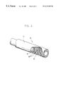
- FIG. 3 illustrates the constitution of the pulverized coal injecting apparatus according to the present invention
- FIGS. 4 a and 4 b are graphical illustrations comparatively showing the oxygen concentration of the conventional apparatus and that of the apparatus of the present invention.
- FIGS. 5 a and 5 b are graphical illustrations comparatively showing the combustion temperature of the conventional apparatus and that of the apparatus of the present invention
- FIG. 6 is a graphical illustration comparatively showing the combustion efficiency in the race way of the conventional apparatus and that in the race way of the apparatus according to the present invention
- FIG. 7 illustrates a second embodiment of the pulverized coal injecting apparatus according to the present invention.
- FIG. 8 illustrates various cross sectional shapes of the dimples according to the presint invention, in which:
- FIGS. 8 ( a ), 8 ( b ) and 8 ( c ) illustrate round cross-sectional shapes; and FIGS. 8 ( d ) and 8 ( e ) illustrate angular cross-sectional shapes;
- FIG. 9 a is a graphical illustration comparatively showing the combustion states (when the oxygen is enriched between the inner and outer pipes of the lance) for the case where W/D is 4, is 2 and is 1, where D indicates the depth of the dimples, and W indicates the width of the dimples;
- FIG. 9 b is a graphical illustration comparatively showing the combustion states for the cases where the ratio D/t between the lance thickness t and the dimple depth D is 0.9, 0.5 and 0, when the oxygen enrichment is carried out between the outer and inner pipes;
- FIG. 9 c is a graphical illustration comparatively showing the oxygen enriching methods for the case where W/D is 2, and where the distance L between the dimples is 0, and L is 1 ⁇ 4 of the outside diameter of the pipe;
- FIG. 9 d is a graphical illustration comparatively showing the oxygen enriching methods for the case where the leading end of the coaxial pipes is expanded by 2 mm, and where dimples having a depth of 2 mm are formed;
- FIG. 10 is a graphical illustration comparatively showing the race ways for the case where W/D is 0.5 to 5.
- a first embodiment of the pulverized coal injecting apparatus basically includes: a cylindrical inner pipe 32 ; a cylindrical outer pipe 31 coaxially surrounding the inner pipe for forming a coaxial pipe structure; and a spiral swirler 33 formed on the surface of the inner pipe 32 .
- the pulverized coal injecting apparatus includes a plurality of semi-spherical dimples 34 formed on the surface of the inner pipe 32 .
- the semi-spherical dimples should be preferably formed over a distance of 100 mm from the leading end of the inner pipe.
- an introduction portion is required for ensuring a stable flow overcoming the agitations which have been caused at the mouth.
- this value corresponds to a 0.05-multiple of the Reynold's number, but in the case of a turbulent flow, it is far shorter.
- the cylindrical inner pipe can feed a liquid fuel or a gaseous fuel into a tuyere.
- the semi-spherical dimples decrease the flow resistance of the combustible fluid which flows between the inner and outer pipes 32 and 31 , thereby improving the mixing owing to the vortex which is generated at the leading end of the injecting apparatus.
- the combustible fluid may be usually oxygen.
- the turbulence degree of the fluid flow is expressed, and for this, the Reynold's number is used.
- the flow is of laminar type, and at 2000 or more, the flow is of turbulent type.
- the turbulent flow at more than 2000 of the Reynold's number, there is a segment where the flow pattern is drastically altered in accordance with the surface conditions of the pipe.
- a combustible fluid is supplied in the range of Reynold's number 2000 to 400,000.
- the intra-pipe resistance is decreased to 1 ⁇ 2, the fluid flow becomes smooth, and the mixing of the fluid at the leading end of the pipe is promoted.
- the currently used oxygen enrichment amount is about 300 Nm 3 /hr, and the Reynold's number for the oxygen flowing through between an outer pipe inside diameter of 41 mm and an inner pipe outside diameter of 34 mm is about 100,000. Accordingly, if the dimples are formed on the surface of the inner pipe, then the combustion efficiency is improved.
- the semi-spherical dimples which are formed on the surface of the inner pipe should be preferably arranged in a zig zag form.
- the conventional coaxial pulverized coal injecting apparatus with the spiral swirler formed thereon and the coaxial pulverized coal injecting apparatus with the dimples formed thereon were subjected to experiments to see the mixing efficiency between oxygen and pulverized coal.
- the experimented results are illustrated in FIG. 4 .
- the oxygen concentration in the inner region was 60%. Further, it was seen that, as the fluid advanced in the axial direction of the pipe, the oxygen was not spread toward the peripheral regions. Therefore, the oxygen concentration at the center of the flow was gradually increased.
- the oxygen gas as an auxiliary combustion material a nitrogen gas as a carrying gas, and a gaseous fuel as a fuel were used to carry out the experiment.
- FIG. 5 illustrates the results of the experiments on the two kinds of the coaxial pipes. Of them, FIG. 5 a illustrates the results of measuring the temperature at the center of the flame, and FIG. 5 b illustrates the results of measuring the temperature at the peripheral region of the flame.
- the results of measuring the temperature of the center of the flame are as shown in FIG. 5 a . That is, in the case of the apparatus of the present invention, a combustion of almost 100% occurred in the first half portion, and therefore, the central temperature of the first half portion was higher by about 200-300° C. compared with the conventional case. In the last half portion, there was no fuel left to be burned, and therefore, the temperature was lowered in the last half portion.
- the temperature of the peripheral regions is illustrated in FIG. 5 b . That is, in the case of the conventional apparatus, the flame temperature in the peripheral regions was lowered by about 200° C. This corresponds to the cold rolling experiment, and this owes to the fact that the oxygen is not spread to the peripheral regions, but is converged to the central regions.
- FIG. 7 illustrates a second embodiment of the pulverized coal injecting apparatus according to the present invention.
- a plurality of dimples 105 are formed on the surface of the leading end of an inner pipe 142 (having a thickness t).
- the depth of the dimples 105 is called D
- the width of the dimples 105 is called W.
- W/D is designed to be 0.5 to 4.
- the Reynold's number becomes 60,000 to 200,000.
- the dimples 105 are formed on surface of the inner pipe 142 , then there was improved the mixing between the fuel flowing through a pulverized coal flow path 150 of the inner pipe 142 and the fluid flowing through between the inner and outer pipes 142 and 145 .
- different effects were generated depending on the shapes of the dimples. Therefore, by adopting the dimples of various shapes as mentioned below, the combustion efficiencies were obtained by experiments.
- the shapes of the dimples 105 were made different in accordance with the depth D of the dimples 105 and the width W of the dimples 105 .
- FIGS. 8 a , 8 b and 8 c illustrate the cases where the cross sectional shape of the dimple is round, while FIGS. 8 d and 8 e illustrate the cases where the cross sectional shape is angular.
- FIG. 9 a is a graphical illustration comparatively showing the combustion states (when the oxygen is enriched between the inner and outer pipes of the lance) for the case where W/D is 4, is 2 and is 1, where D indicates the depth of the dimples, and W indicates the width of the dimples.
- W/D was 2. That is, when W/D was 2, to be superior the temperature at a first point from the leading end was very high. The temperature at a second point was also high, while the temperatures at third, fourth and fifth points (where the residual fuel was burned) were low. In view of this, the combustion efficiency was highest in the case where W/D was 2.
- FIG. 9 b is a graphical illustration comparatively showing the combustion states for the cases where the ratio D/t between the lance thickness t and the dimple depth D was 0.9, 0.5 and 0, when the oxygen enrichment was carried out between the outer and inner pipes. The combustion efficiency was most superior in the case where D/t was 0.9.
- FIG. 9 c is a graphical illustration comparatively showing the oxygen enriching methods for the case where W/D was 2, and where the distance L between the dimples was 0, and where L was 1 ⁇ 4 of the outside diameter of the pipe.
- the experimental result showed to be as follows. That is, the case where the distance L between the dimples 105 was 0, that is, the case where the dimples 105 were arranged in a zig zag form, showed the highest combustion efficiency. This shows the number of the dimples 105 . If the number of the dimples is large, the combustion efficiency was greatly improved. Under the same principle, if the number of the dimples 105 was large, then the initial and highest temperature were very high, while the temperature of the last half portion was low.
- FIG. 9 d is a graphical illustration comparatively showing the oxygen enriching methods for the case where the leading end of the coaxial pipes was expanded by 2 mm, and where dimples having a depth of 2 mm were formed. The result showed that the combustion efficiency was greatly improved owing to the effect of the dimples 105 . In the case of the conventional apparatus, the temperature in the last half portion was very high due to the combustion of the residual oxygen.
- FIG. 8 a illustrates the cross sectional shape of the dimple 105 , for the case where W/D was 4.
- FIG. 8 c illustrates the cross sectional shape of the dimple 105 , for the case where W/D was 0.5. All of these cases showed superior combustion efficiencies compared with the conventional apparatus.
- FIG. 10 is a graphical illustration comparatively showing the race ways for the case where W/D of the dimple was 0.5 to 4 according to the present invention, and for the case of the conventional apparatus.
- the temperature was raised by more than 50° C. compared with the conventional case.
- the fluid flow becomes efficient to improve the combustion efficiency for the pulverized coal, and therefore, the oxygen enrichment cost and the fuel cost can be saved.
- the dimples can be formed on the inner surface of inner pipe, in case of injecting a pulverized coal through between the outer and inner pipes, and injecting the combustible fluid through the inner pipe.
- the fuel cost is curtailed through the improvement of the combustion efficiency, and since the unburnt coal fines can be prevented from being accumulated, the stability of the furnace operating conditions can be ensured.
Landscapes
- Engineering & Computer Science (AREA)
- Chemical & Material Sciences (AREA)
- Manufacturing & Machinery (AREA)
- Materials Engineering (AREA)
- Metallurgy (AREA)
- Organic Chemistry (AREA)
- Manufacture Of Iron (AREA)
- Blast Furnaces (AREA)
Abstract
A pulverized coal injecting apparatus includes a cylindrical inner pipe for feeding pulverized coal into a tuyere of a blast furnace. A cylindrical outer pipe coaxially surrounds the inner pipe. A spiral swirler is formed on the surface of the inner pipe and the pulverized coal is supplied through the inner pipe, while a combustible fluid is supplied through a space defined between the outer and inner pipes. The pulverized coal injecting apparatus further includes a plurality of dimples formed on a surface of a leading end portion of the inner pipe for reducing fluid flow resistance so as to improve the mixing of the pulverized coal with the combustible fluid. The fluid flow becomes efficient so as to improve the combustion efficiency of the pulverized coal. Thus, the oxygen enrichment cost and fuel costs are reduced.
Description
This application is a 371 filing of PCT/KR99/00440 filed on Sep. 8, 1999.
The present invention relates to a pulverized coal injecting apparatus in which oxygen is used to improve the combustion of pulverized coal in a blast furnace using the pulverized coal instead of the expensive coal in a pig iron manufacturing process. Particularly the present invention relates to a pulverized coal injecting apparatus in which dimples are formed on the surface if an inner pipe to improve the combustion of the pulverized coal.
Generally in a pig iron manufacturing process of a blast furnace, as shown in FIG. 1(a), iron ore as a raw material and coke as a fuel are fed through the top of the furnace, while hot air is fed through a tuyere which is formed on a lower portion of the furnace. Thus, the coke is burned, thereby producing pig iron and slag. In accordance with the progress in the pig iron manufacturing process of the blast furnace, at present, expensive coke is replaced with the pulverized coal by using a pulverized coal injecting apparatus 4 in which tuyere is formed to feed the pulverized coal. In the case of a blast furnace in which this pulverized coal is fed as described above, a large cavity which is called a race way (combustion area) 3 is formed on the front of the tuyere due to the high temperature air flow. FIG. 1(b) illustrates in detail the race way 3.
Most of the coke and the pulverized coal are burned in the race way (combustion area) to supply the heat which is required in reducing the ore. However, depending on cases, the unburnt pulverized coal passes through the coke layer within the blast furnace, to be partly discharged to the outside of the furnace, and to be partly accumulated within the coke layer in which the gas velocity is relatively slow. This accumulated unburnt pulverized coal remains within the inner region of the furnace to alter the gas flow. Further, it lowers the intra-furnace temperature, and increases the permeability resistance, with the result that the size of the race way is decreased. As the pulverized coal feeding amount is increased, the decrease of the combustion efficiency of the pulverized coal becomes very serious, with the result that the manufacturing cost of the pig iron is increased.
In order to solve this problem, in the general technique, pure oxygen is enriched, thereby improving the combustion efficiency of the pulverized coal. By carrying out the pure oxygen enrichment through the tuyere, the oxygen concentration in the hot air flow is increased so, as to promote the combustion of the pulverized coal. However, in this method, the flow amount of the hot blast is very large, and therefore, even if oxygen is enriched to a high degree, the actual oxygen concentration increases just by several percent, with the result that the final effect is meager. Further, the cost of newly building the oxygen producing facilities is very high, and therefore, there is a limit in carrying out the oxygen enrichment.
Meanwhile, in order to solve the above described problem, recently, efforts have been concentrated on modifying the structure of the pulverized coal injecting apparatus.
FIG. 2a illustrates one example of this. As shown in this drawing, a pulverized coal injecting apparatus 10 is of a coaxial type, and the pulverized coal is fed through an inner pipe 12, while pure oxygen is enriched in an outer pipe 11. Thus the oxygen concentration is raised to improve the combustion efficiency. In this method, the combustion efficiency is somewhat improved compared with the case of carrying out the hot blast oxygen enrichment. In this method, however, the external oxygen cannot intrude into the pulverized coal flow, but burns only in the outer regions.
FIG. 2b illustrates another effort of solving the above described problem. In this method, an oxygen flow swirler 23 is formed between the coaxial pipes, so as to form a vortex in the inner region of the pulverized coal flow. However, as has been widely recognized, the effect of installing the swirler depends on how suitable it is to the structure of the burner. In other words, if the spiral angle is too deep, the oxygen is directed to the outside of the pulverized coal flow rather than the inner region, with the result that the combustion efficiency is lowered. On the other hand, if these angle is too shallow, it is not different from the case of the general coaxial lance as shown in FIG. 2a.
As still another example of the efforts, there is a single piped expanded pulverized coal injecting apparatus in which the diameter of the single pipe is sufficiently expanded so as to cause a turbulent pulverized coal flow in the leading end of the feeding pipe. In this method, however, there is required a large scale improvement in the auxiliary facilities. Further, if an expanded pipe is installed within the tuyere, the cross sectional area of the tuyere is decreased, thereby impeding the introduction of the hot blast into the blast furnace so as to lower the productivity.
As still another attempt, there is an eccentric double-lance in which two single pipes are set to improve the combustion efficiency. However, if two pulverized coal injecting pipes are installed within a single tuyere, then the cross sectional area is decreased as described above, and therefore, not only are to the productivity and furnace condition stability, adversely effected but also management becomes troublesome since the number of the injecting pipes is doubled.
Besides, in still another attempt, the oxygen feeding angle is altered to forcibly mix the oxygen into the pulverized coal flow. In this case, however, although the combustion efficiency is improved, the flame width is expanded to cause damages in the tuyere. Further, the leading end of the pipe is slightly protruded to alter the feeding angle, and therefore, the protrusion is worn out due to the continuous collisions with the pulverized coal flow.
The present invention is intended to overcome the above described disadvantages of the conventional techniques.
Therefore it is an object of the present invention to provide a pulverized coal injecting apparatus in which the tuyere of the blast furnace or the like is not damaged, and yet the combustion efficiency of the pulverized coal is markedly improved.
In achieving the above object, the pulverized coal injecting apparatus according to the present invention includes: a cylindrical inner pipe for feeding a pulverized coal into a tuyere; a cylindrical outer pipe coaxially surrounding the inner pipe; a spiral swirler formed on a surface of the inner pipe; the pulverized coal being supplied through the inner pipe; and a combustible fluid being supplied through between the outer and inner pipes. The pulverized coal injecting apparatus further includes: a plurality of dimples formed on the surface of the leading end portion of the inner pipe, for reducing a fluid flow resistance to improve the mixing of the pulverized coal with the fluid.
In another aspect of the present invention, the pulverized coal injecting apparatus according to the present invention includes: a cylindrical inner pipe for feeding a pulverized coal into a tuyere; a cylindrical outer pipe coaxially surrounding the inner pipe; a spiral flow path formed on the surface of the inner pipe; a pulverized coal being fed through the inner pipe; and a combustible fluid being fed through between the inner and outer pipes. The pulverized coal injecting apparatus further includes: a plurality of dimples formed on a part of the surface of the leading end portion of the inner pipe; and W/D=0.5 to 4, where D indicates a depth of the dimples, and W indicates a width of the dimples.
The above object and other advantages of the present invention will become more apparent by describing in detail the preferred embodiment of the present invention with reference to the attached drawings in which:
FIGS. 1a and 1 b illustrate the operating status of the general blast furnace;
FIGS. 2a and 2 b illustrate the conventional pulverized coal injecting apparatus;
FIG. 3 illustrates the constitution of the pulverized coal injecting apparatus according to the present invention;
FIGS. 4a and 4 b are graphical illustrations comparatively showing the oxygen concentration of the conventional apparatus and that of the apparatus of the present invention;
FIGS. 5a and 5 b are graphical illustrations comparatively showing the combustion temperature of the conventional apparatus and that of the apparatus of the present invention;
FIG. 6 is a graphical illustration comparatively showing the combustion efficiency in the race way of the conventional apparatus and that in the race way of the apparatus according to the present invention;
FIG. 7 illustrates a second embodiment of the pulverized coal injecting apparatus according to the present invention;
FIG. 8 illustrates various cross sectional shapes of the dimples according to the presint invention, in which:
FIGS. 8(a), 8(b) and 8(c) illustrate round cross-sectional shapes; and FIGS. 8(d) and 8(e) illustrate angular cross-sectional shapes;
FIG. 9a is a graphical illustration comparatively showing the combustion states (when the oxygen is enriched between the inner and outer pipes of the lance) for the case where W/D is 4, is 2 and is 1, where D indicates the depth of the dimples, and W indicates the width of the dimples;
FIG. 9b is a graphical illustration comparatively showing the combustion states for the cases where the ratio D/t between the lance thickness t and the dimple depth D is 0.9, 0.5 and 0, when the oxygen enrichment is carried out between the outer and inner pipes;
FIG. 9c is a graphical illustration comparatively showing the oxygen enriching methods for the case where W/D is 2, and where the distance L between the dimples is 0, and L is ¼ of the outside diameter of the pipe;
FIG. 9d is a graphical illustration comparatively showing the oxygen enriching methods for the case where the leading end of the coaxial pipes is expanded by 2 mm, and where dimples having a depth of 2 mm are formed; and
FIG. 10 is a graphical illustration comparatively showing the race ways for the case where W/D is 0.5 to 5.
As shown in FIG. 3, a first embodiment of the pulverized coal injecting apparatus according to the present invention basically includes: a cylindrical inner pipe 32; a cylindrical outer pipe 31 coaxially surrounding the inner pipe for forming a coaxial pipe structure; and a spiral swirler 33 formed on the surface of the inner pipe 32.
Unlike the conventional pulverized coal injecting apparatuses, the pulverized coal injecting apparatus according to the present invention includes a plurality of semi-spherical dimples 34 formed on the surface of the inner pipe 32. The semi-spherical dimples should be preferably formed over a distance of 100 mm from the leading end of the inner pipe. In the case of a fluid flowing through between the two pipes, an introduction portion is required for ensuring a stable flow overcoming the agitations which have been caused at the mouth. In the case of a laminar flow, this value corresponds to a 0.05-multiple of the Reynold's number, but in the case of a turbulent flow, it is far shorter. In the case of the present invention, with a turbulent flow over the length of 100 mm, a fully developed fluid flow could be obtained. The cylindrical inner pipe can feed a liquid fuel or a gaseous fuel into a tuyere.
The semi-spherical dimples decrease the flow resistance of the combustible fluid which flows between the inner and outer pipes 32 and 31, thereby improving the mixing owing to the vortex which is generated at the leading end of the injecting apparatus. In the above, the combustible fluid may be usually oxygen.
In expressing the flow of the fluid, the turbulence degree of the fluid flow is expressed, and for this, the Reynold's number is used.
Reynold's number=pipe diameter×velocity×fluid density/fluid viscosity
At a Reynold's number of 2000 or less, the flow is of laminar type, and at 2000 or more, the flow is of turbulent type. In the case of the turbulent flow at more than 2000 of the Reynold's number, there is a segment where the flow pattern is drastically altered in accordance with the surface conditions of the pipe. Thus, in the present invention, a combustible fluid is supplied in the range of Reynold's number 2000 to 400,000.
In the case of the semi-spherical dimples of the present invention, at a Reynold's number of 40,000 to 400,000, the intra-pipe resistance is decreased to ½, the fluid flow becomes smooth, and the mixing of the fluid at the leading end of the pipe is promoted. The currently used oxygen enrichment amount is about 300 Nm3/hr, and the Reynold's number for the oxygen flowing through between an outer pipe inside diameter of 41 mm and an inner pipe outside diameter of 34 mm is about 100,000. Accordingly, if the dimples are formed on the surface of the inner pipe, then the combustion efficiency is improved. Here, the semi-spherical dimples which are formed on the surface of the inner pipe should be preferably arranged in a zig zag form.
Now the present invention will be described based on actual experimental examples.
The conventional coaxial pulverized coal injecting apparatus with the spiral swirler formed thereon and the coaxial pulverized coal injecting apparatus with the dimples formed thereon were subjected to experiments to see the mixing efficiency between oxygen and pulverized coal. The experimented results are illustrated in FIG. 4.
In the case of FIG. 4a in which only the conventional spiral swirler is adopted, the oxygen concentration in the inner region was 50%. Further, it was seen that, as the fluid advanced in the axial direction of the pipe, the oxygen was spread toward the peripheral regions, and that the mixing efficiency between the pulverized coal and the oxygen was lowered.
On the other hand, in the case of FIG. 4b in which the apparatus of the present invention was utilized, the oxygen concentration in the inner region was 60%. Further, it was seen that, as the fluid advanced in the axial direction of the pipe, the oxygen was not spread toward the peripheral regions. Therefore, the oxygen concentration at the center of the flow was gradually increased.
In order to see the combustion efficiencies of the two kinds of the coaxial pipes, the oxygen gas as an auxiliary combustion material, a nitrogen gas as a carrying gas, and a gaseous fuel as a fuel were used to carry out the experiment.
FIG. 5 illustrates the results of the experiments on the two kinds of the coaxial pipes. Of them, FIG. 5a illustrates the results of measuring the temperature at the center of the flame, and FIG. 5b illustrates the results of measuring the temperature at the peripheral region of the flame.
The results of measuring the temperature of the center of the flame are as shown in FIG. 5a. That is, in the case of the apparatus of the present invention, a combustion of almost 100% occurred in the first half portion, and therefore, the central temperature of the first half portion was higher by about 200-300° C. compared with the conventional case. In the last half portion, there was no fuel left to be burned, and therefore, the temperature was lowered in the last half portion.
Meanwhile, the temperature of the peripheral regions is illustrated in FIG. 5b. That is, in the case of the conventional apparatus, the flame temperature in the peripheral regions was lowered by about 200° C. This corresponds to the cold rolling experiment, and this owes to the fact that the oxygen is not spread to the peripheral regions, but is converged to the central regions.
When carrying out the blast furnace operation, in order to compare the actual combustion efficiencies in the race ways, a pulverized coal of 150 Kg/t-p and an oxygen enrichment of 10,000 Nm3/hr were adopted in 34 pulverized coal injecting devices. Thus the highest temperatures in the race ways were measured, and the results are shown in FIG. 6.
As shown in FIG. 6, in the apparatus of the present invention compared with the conventional apparatus, the combustion efficiency was increased by about 1-2%, and because of this, the fuel ratio was decreased by about 2 Kg/ton-pig.
FIG. 7 illustrates a second embodiment of the pulverized coal injecting apparatus according to the present invention.
In this second embodiment of the pulverized coal injecting apparatus of the present invention, a plurality of dimples 105 are formed on the surface of the leading end of an inner pipe 142 (having a thickness t). The depth of the dimples 105 is called D, and the width of the dimples 105 is called W. Under these assumptions, W/D is designed to be 0.5 to 4. In the case where the currently using oxygen enrichment is 20 to 400 Nm3/hr, and where the oxygen passes through between an outer pipe 145 (having an inside diameter of 41 mm) and an inner pipe 142 (having an outside diameter of 31 mm), the Reynold's number becomes 60,000 to 200,000. Therefore, if the dimples 105 are formed on surface of the inner pipe 142, then there was improved the mixing between the fuel flowing through a pulverized coal flow path 150 of the inner pipe 142 and the fluid flowing through between the inner and outer pipes 142 and 145. However, different effects were generated depending on the shapes of the dimples. Therefore, by adopting the dimples of various shapes as mentioned below, the combustion efficiencies were obtained by experiments.
As illustrated in FIG. 8, the shapes of the dimples 105 were made different in accordance with the depth D of the dimples 105 and the width W of the dimples 105. The case where the diameter of the bottom of the dimple is different from the diameter of the top of the dimple, the case where the former was same as the latter, and the case where the former was larger than the latter, were distinguished. FIGS. 8a, 8 b and 8 c illustrate the cases where the cross sectional shape of the dimple is round, while FIGS. 8d and 8 e illustrate the cases where the cross sectional shape is angular.
FIG. 9a is a graphical illustration comparatively showing the combustion states (when the oxygen is enriched between the inner and outer pipes of the lance) for the case where W/D is 4, is 2 and is 1, where D indicates the depth of the dimples, and W indicates the width of the dimples. According to these experiments, the results showed the case where W/D was 2. That is, when W/D was 2, to be superior the temperature at a first point from the leading end was very high. The temperature at a second point was also high, while the temperatures at third, fourth and fifth points (where the residual fuel was burned) were low. In view of this, the combustion efficiency was highest in the case where W/D was 2.
FIG. 9b is a graphical illustration comparatively showing the combustion states for the cases where the ratio D/t between the lance thickness t and the dimple depth D was 0.9, 0.5 and 0, when the oxygen enrichment was carried out between the outer and inner pipes. The combustion efficiency was most superior in the case where D/t was 0.9.
FIG. 9c is a graphical illustration comparatively showing the oxygen enriching methods for the case where W/D was 2, and where the distance L between the dimples was 0, and where L was ¼ of the outside diameter of the pipe. The experimental result showed to be as follows. That is, the case where the distance L between the dimples 105 was 0, that is, the case where the dimples 105 were arranged in a zig zag form, showed the highest combustion efficiency. This shows the number of the dimples 105. If the number of the dimples is large, the combustion efficiency was greatly improved. Under the same principle, if the number of the dimples 105 was large, then the initial and highest temperature were very high, while the temperature of the last half portion was low.
FIG. 9d is a graphical illustration comparatively showing the oxygen enriching methods for the case where the leading end of the coaxial pipes was expanded by 2 mm, and where dimples having a depth of 2 mm were formed. The result showed that the combustion efficiency was greatly improved owing to the effect of the dimples 105. In the case of the conventional apparatus, the temperature in the last half portion was very high due to the combustion of the residual oxygen.
The combustion efficiency was almost the same in the different shapes of the dimples as shown in FIG. 8. FIG. 8a illustrates the cross sectional shape of the dimple 105, for the case where W/D was 4. FIG. 8c illustrates the cross sectional shape of the dimple 105, for the case where W/D was 0.5. All of these cases showed superior combustion efficiencies compared with the conventional apparatus.
FIG. 10 is a graphical illustration comparatively showing the race ways for the case where W/D of the dimple was 0.5 to 4 according to the present invention, and for the case of the conventional apparatus.
As shown in this drawing, the temperature was raised by more than 50° C. compared with the conventional case.
According to the present invention as described above, the fluid flow becomes efficient to improve the combustion efficiency for the pulverized coal, and therefore, the oxygen enrichment cost and the fuel cost can be saved.
And also, the dimples can be formed on the inner surface of inner pipe, in case of injecting a pulverized coal through between the outer and inner pipes, and injecting the combustible fluid through the inner pipe.
Further, according to the present invention, since the fuel cost is curtailed through the improvement of the combustion efficiency, and since the unburnt coal fines can be prevented from being accumulated, the stability of the furnace operating conditions can be ensured.
Claims (14)
1. A pulverized coal injecting apparatus comprising:
a cylindrical inner pipe for feeding a pulverized coal into a tuyere;
a cylindrical outer pipe coaxially surrounding said inner pipe;
a spiral swirler formed on a surface of said inner pipe;
the pulverized coal being supplied through said inner pipe; and
a combustible fluid being supplied through between said outer and inner pipes,
the pulverized coal injecting apparatus further comprising:
a plurality of dimples formed on a surface of a leading end portion of said inner pipe, for reducing a fluid flow resistance to improve a mixing of the pulverized coal with a fluid.
2. The pulverized coal injecting apparatus as claimed in claim 1, wherein said dimples are formed on a portion within 100 mm from a leading end of said inner pipe.
3. The pulverized coal injecting apparatus as claimed in claim 1, wherein said dimples are formed in a zig zag form.
4. The pulverized coal injecting apparatus as claimed in claim 1, wherein said dimples have a semi-spherical cross section.
5. The pulverized coal injecting apparatus as claimed in claim 1, said dimples are formed on the inner surface of inner pipe, in case of injecting a pulverized coal through between said outer and inner pipes, and injecting said combustible fluid through said inner pipe.
6. A pulverized coal injecting apparatus comprising:
a cylindrical inner pipe for feeding a pulverized coal into a tuyere;
a cylindrical outer pipe coaxially surrounding said inner pipe;
a spiral flow path formed on a surface of said inner pipe;
a pulverized coal being fed through said inner pipe; and
a combustible fluid being fed through between said inner and outer pipes,
the pulverized coal injecting apparatus further comprising:
a plurality of dimples formed on a part of a surface of a leading end portion of said inner pipe, W/D being 0.5 to 4, where D indicates a depth of said dimples, and W indicates a width of said dimples.
7. The pulverized coal injecting apparatus as claimed in claim 6, wherein W/D is 2.
8. The pulverized coal injecting apparatus as claimed in claim 6, wherein a distance L between said dimples is 0.
9. The pulverized coal injecting apparatus as claimed in claim 6, wherein said dimples have an angular cross-sectional shape.
10. A pulverized coal injecting apparatus comprising:
a cylindrical inner pipe for feeding a pulverized coal into a tuyere;
a cylindrical outer pipe coaxially surrounding said inner pipe;
a spiral flow path formed on a surface of said inner pipe;
a pulverized coal being fed through said inner pipe; and
a combustible fluid being fed through between said inner and outer pipes,
the pulverized coal injecting apparatus further comprising:
a plurality of dimples formed on a part of a surface of a leading end portion of said inner pipe, said dimples having a depth as large as a thickness of said inner pipe permits.
11. The pulverized coal injecting apparatus as claimed in claim 2, wherein said dimples have a semi-spherical cross section.
12. The pulverized coal injecting apparatus as claimed in claim 3, wherein said dimples have a semi-spherical cross section.
13. The pulverized coal injecting apparatus as claimed in claim 7, wherein said dimples have an angular cross-sectional shape.
14. The pulverized coal injecting apparatus as claimed in claim 8, wherein said dimples have an angular cross-sectional shape.
Applications Claiming Priority (5)
| Application Number | Priority Date | Filing Date | Title |
|---|---|---|---|
| KR98-15221 | 1998-08-13 | ||
| KR2019980015221U KR200278280Y1 (en) | 1998-08-13 | 1998-08-13 | Pulverized coal blow lance |
| KR10-1999-0029067A KR100380747B1 (en) | 1999-07-19 | 1999-07-19 | A pulverized coal injection apparatus utilizing duplex pipe |
| KR99-29067 | 1999-07-19 | ||
| PCT/KR1999/000440 WO2000009763A1 (en) | 1998-08-13 | 1999-08-09 | Pulverized coal injecting apparatus |
Publications (1)
| Publication Number | Publication Date |
|---|---|
| US6319458B1 true US6319458B1 (en) | 2001-11-20 |
Family
ID=26633608
Family Applications (1)
| Application Number | Title | Priority Date | Filing Date |
|---|---|---|---|
| US09/509,711 Expired - Fee Related US6319458B1 (en) | 1998-08-13 | 1999-09-08 | Pulverized coal injecting apparatus |
Country Status (6)
| Country | Link |
|---|---|
| US (1) | US6319458B1 (en) |
| EP (1) | EP1060272B1 (en) |
| JP (1) | JP3379946B2 (en) |
| CN (1) | CN1093882C (en) |
| DE (1) | DE69913664T2 (en) |
| WO (1) | WO2000009763A1 (en) |
Cited By (13)
| Publication number | Priority date | Publication date | Assignee | Title |
|---|---|---|---|---|
| US20050241605A1 (en) * | 2004-04-29 | 2005-11-03 | Bedwell Donald R | Fluid flow surface with indentations |
| US20060040223A1 (en) * | 2003-01-21 | 2006-02-23 | Ghani M U | Method and apparatus for injecting a gas into a two-phase stream |
| US20060260521A1 (en) * | 2005-05-19 | 2006-11-23 | Hanson Simon P | Apparatus for reducing NOx emissions in furnaces through the concentration of solid fuel as compared to air |
| US20070205543A1 (en) * | 2006-03-06 | 2007-09-06 | Lanyi Michael D | Oxidant-swirled fossil fuel injector for a shaft furnace |
| US20090162652A1 (en) * | 2007-12-21 | 2009-06-25 | Ranade Aditya P | Co-extruded fluoropolymer multilayer laminates |
| US20110016790A1 (en) * | 2008-03-05 | 2011-01-27 | Basf Se | Process and apparatus for thermal partial oxidation of hydrocarbons |
| US20120073692A1 (en) * | 2010-06-24 | 2012-03-29 | Isco Industries, Llc | Modified pipe inlet |
| CN103088173A (en) * | 2011-11-01 | 2013-05-08 | 张昭贵 | Blast furnace coal injection device, and mounting and operating methods thereof |
| US20130146680A1 (en) * | 2011-12-09 | 2013-06-13 | United States Steel Corporation | Injection lance with variable swirl |
| WO2015198285A1 (en) | 2014-06-27 | 2015-12-30 | Tubitak | A coal feeding system |
| US20160074617A1 (en) * | 2013-05-13 | 2016-03-17 | Arizona Board Of Regents On Behalf Of The University Of Arizona | Aerostasis in Pulmonary Surgery |
| US9938593B2 (en) | 2013-04-03 | 2018-04-10 | Jfe Steel Corporation | Blast furnace operation method |
| EP4283233A1 (en) * | 2011-12-21 | 2023-11-29 | JFE Steel Corporation | Double wall lance |
Families Citing this family (10)
| Publication number | Priority date | Publication date | Assignee | Title |
|---|---|---|---|---|
| LU91264B1 (en) | 2006-07-12 | 2008-01-14 | Wurth Paul Sa | Pulverized coal injection lance |
| CN101270873B (en) * | 2007-03-23 | 2011-06-15 | 宝山钢铁股份有限公司 | Method and device for blowing breeze to pure oxygen smelting mobile filling bed smelting furnace |
| LU91445B1 (en) | 2008-05-23 | 2009-11-24 | Wurth Paul Sa | Method for feeding pulverised coal into a blast furnace |
| LU91543B1 (en) * | 2009-03-24 | 2010-09-27 | Wurth Paul Sa | Tuyere stock arrangement for a blast furnace and method for operating a blast furnace |
| CN101948940B (en) * | 2010-09-03 | 2012-05-02 | 南通海鹰机电集团有限公司 | Efficient, safe and environment-friendly blasting device |
| EP2726827B1 (en) * | 2011-06-30 | 2019-12-11 | University of Canterbury | Flow rate determination method and apparatus |
| DE102014216336A1 (en) | 2014-08-18 | 2016-02-18 | Küttner Holding GmbH & Co. KG | Process for injecting replacement reductants into a blast furnace |
| CN115448773B (en) * | 2022-10-25 | 2024-04-19 | 艾克杰生物科技(黑龙江)有限公司 | Biological organic fertilizer and processing technology thereof |
| CN116678219B (en) * | 2023-05-17 | 2023-11-03 | 贵州麒臻实业集团有限公司 | Furnace pulverized coal injection system device |
| CN117487979A (en) * | 2023-11-27 | 2024-02-02 | 山东钢铁集团永锋临港有限公司 | Method for improving oxygen enrichment rate and pulverized coal combustion rate of blast furnace |
Citations (3)
| Publication number | Priority date | Publication date | Assignee | Title |
|---|---|---|---|---|
| US2454892A (en) * | 1946-05-22 | 1948-11-30 | John H Sprow | Blast furnace tuyere |
| US4434976A (en) * | 1981-12-11 | 1984-03-06 | Nippon Steel Corporation | Concentric multi-tube-system nozzle situated beneath the surface of the melt in a refining vessel |
| US5333840A (en) | 1991-01-17 | 1994-08-02 | SSAB Tunnplåt AB | Blast pipe and tuyere arrangement for a blast furnace and method |
Family Cites Families (3)
| Publication number | Priority date | Publication date | Assignee | Title |
|---|---|---|---|---|
| US3758090A (en) * | 1971-03-26 | 1973-09-11 | Nippon Kokan Kk | Combustion apparatus for blast furnaces |
| JPS59502109A (en) * | 1982-09-03 | 1984-12-20 | ナウチノ−プロイズヴオドストウエンノエ オビエデイネニエ゛トウラチエルメト″ | metal bottom blowing tuyere |
| US5411393A (en) * | 1993-01-04 | 1995-05-02 | Southwire Company | Premix burner for furnace with gas enrichment |
-
1999
- 1999-08-09 CN CN99801352A patent/CN1093882C/en not_active Expired - Fee Related
- 1999-08-09 DE DE69913664T patent/DE69913664T2/en not_active Expired - Fee Related
- 1999-08-09 EP EP99938619A patent/EP1060272B1/en not_active Expired - Lifetime
- 1999-08-09 WO PCT/KR1999/000440 patent/WO2000009763A1/en active IP Right Grant
- 1999-08-09 JP JP2000565196A patent/JP3379946B2/en not_active Expired - Fee Related
- 1999-09-08 US US09/509,711 patent/US6319458B1/en not_active Expired - Fee Related
Patent Citations (3)
| Publication number | Priority date | Publication date | Assignee | Title |
|---|---|---|---|---|
| US2454892A (en) * | 1946-05-22 | 1948-11-30 | John H Sprow | Blast furnace tuyere |
| US4434976A (en) * | 1981-12-11 | 1984-03-06 | Nippon Steel Corporation | Concentric multi-tube-system nozzle situated beneath the surface of the melt in a refining vessel |
| US5333840A (en) | 1991-01-17 | 1994-08-02 | SSAB Tunnplåt AB | Blast pipe and tuyere arrangement for a blast furnace and method |
Non-Patent Citations (6)
| Title |
|---|
| B{acute over (ee)}r, J.M. et al., "Combustion Aerodynamics," Chapter 5, "Swirling Flows," pp. 100-145, Applied Science Publishers LtdDec. 1957. |
| Maki, Akira et al., "High Rate Coal Injection of 218 kg/t at Fukuyama No. 4 Blast Furnace," ISIJ International, vol. 36 (1996), No. 6, pp. 650-657, Dec. 1996. |
| Peters, K.H. et al., "Effect of High Levels of Coal Injection on Blast Furnace Operation," 2nd European Ironmaking Congress, pp. 247-262, No Date. |
| Takeda, Kanji et al., "Integrated Mathematical Model of Pulverised Coal Combustion in a Blast Furnace," ISIJ International, vol. 37 (1997), No. 5, pp. 432-440, Dec. 1997. |
| Wikström, J.O. et al., "SSAB/MEFOS Oxy-Coal System -3 Years of Industrial Experience," 1996 Ironmaking Conference Proceedings, pp. 61-66, Dec. 1996. |
| Wikström, J.O. et al., "SSAB/MEFOS Oxy-Coal System —3 Years of Industrial Experience," 1996 Ironmaking Conference Proceedings, pp. 61-66, Dec. 1996. |
Cited By (21)
| Publication number | Priority date | Publication date | Assignee | Title |
|---|---|---|---|---|
| US20060040223A1 (en) * | 2003-01-21 | 2006-02-23 | Ghani M U | Method and apparatus for injecting a gas into a two-phase stream |
| US7914279B2 (en) | 2003-01-21 | 2011-03-29 | American Air Liquide, Inc. | Method and apparatus for injecting a gas into a two-phase stream |
| US20050241605A1 (en) * | 2004-04-29 | 2005-11-03 | Bedwell Donald R | Fluid flow surface with indentations |
| US20060260521A1 (en) * | 2005-05-19 | 2006-11-23 | Hanson Simon P | Apparatus for reducing NOx emissions in furnaces through the concentration of solid fuel as compared to air |
| US7472657B2 (en) | 2005-05-19 | 2009-01-06 | Fuel And Furnace Consulting, Inc. | Apparatus for reducing NOx emissions in furnaces through the concentration of solid fuel as compared to air |
| US20070205543A1 (en) * | 2006-03-06 | 2007-09-06 | Lanyi Michael D | Oxidant-swirled fossil fuel injector for a shaft furnace |
| US20090162652A1 (en) * | 2007-12-21 | 2009-06-25 | Ranade Aditya P | Co-extruded fluoropolymer multilayer laminates |
| US20110016790A1 (en) * | 2008-03-05 | 2011-01-27 | Basf Se | Process and apparatus for thermal partial oxidation of hydrocarbons |
| US8801814B2 (en) * | 2008-03-05 | 2014-08-12 | Basf Se | Process and apparatus for thermal partial oxidation of hydrocarbons |
| US8973616B2 (en) * | 2010-06-24 | 2015-03-10 | Isco Industries, Inc. | Modified pipe inlet |
| US20120073692A1 (en) * | 2010-06-24 | 2012-03-29 | Isco Industries, Llc | Modified pipe inlet |
| CN103088173A (en) * | 2011-11-01 | 2013-05-08 | 张昭贵 | Blast furnace coal injection device, and mounting and operating methods thereof |
| US20130146680A1 (en) * | 2011-12-09 | 2013-06-13 | United States Steel Corporation | Injection lance with variable swirl |
| US8919670B2 (en) * | 2011-12-09 | 2014-12-30 | United States Steel Corporation | Injection lance with variable swirl |
| EP4283233A1 (en) * | 2011-12-21 | 2023-11-29 | JFE Steel Corporation | Double wall lance |
| US9938593B2 (en) | 2013-04-03 | 2018-04-10 | Jfe Steel Corporation | Blast furnace operation method |
| US20160074617A1 (en) * | 2013-05-13 | 2016-03-17 | Arizona Board Of Regents On Behalf Of The University Of Arizona | Aerostasis in Pulmonary Surgery |
| US10188824B2 (en) * | 2013-05-13 | 2019-01-29 | The Arizona Board Of Regents On Behalf Of The University Of Arizona | Aerostasis in pulmonary surgery |
| US11013880B2 (en) | 2013-05-13 | 2021-05-25 | Arizona Board Of Regents On Behalf Of The University Of Arizona | Aerostasis in pulmonary surgery |
| WO2015198285A1 (en) | 2014-06-27 | 2015-12-30 | Tubitak | A coal feeding system |
| US9982206B2 (en) | 2014-06-27 | 2018-05-29 | Tubitak | Coal feeding system |
Also Published As
| Publication number | Publication date |
|---|---|
| EP1060272A1 (en) | 2000-12-20 |
| DE69913664D1 (en) | 2004-01-29 |
| EP1060272B1 (en) | 2003-12-17 |
| JP2002522639A (en) | 2002-07-23 |
| CN1275168A (en) | 2000-11-29 |
| WO2000009763A1 (en) | 2000-02-24 |
| DE69913664T2 (en) | 2004-09-30 |
| CN1093882C (en) | 2002-11-06 |
| JP3379946B2 (en) | 2003-02-24 |
Similar Documents
| Publication | Publication Date | Title |
|---|---|---|
| US6319458B1 (en) | Pulverized coal injecting apparatus | |
| ES2265586T3 (en) | INJECTOR FOR METAL FOUNDING OVEN. | |
| US8080200B2 (en) | Pulverized coal injection lance | |
| US20070205543A1 (en) | Oxidant-swirled fossil fuel injector for a shaft furnace | |
| CN102822356A (en) | Blast furnace tuyere cooling | |
| AU2517500A (en) | Multiple coherent jet lance | |
| CN112239798B (en) | Tuyere for basic oxygen converter | |
| JP2009139081A (en) | Burner lance for charging powdery and granular matter of smelting reduction furnace and manufacturing method of molten metal by smelting reduction | |
| KR100782684B1 (en) | Solid fuel blowing device of blast furnace fine powder | |
| KR100380747B1 (en) | A pulverized coal injection apparatus utilizing duplex pipe | |
| JP3733601B2 (en) | Apparatus for injecting pulverized coal for blast furnace and method for injecting pulverized coal in blast furnace | |
| KR200278280Y1 (en) | Pulverized coal blow lance | |
| EP3266883B1 (en) | Blast furnace operating method | |
| EP3266882B1 (en) | Method for operating blast furnace | |
| JP3493937B2 (en) | How to blow pulverized coal into the blast furnace | |
| JP4747662B2 (en) | Lance for blowing gas reducing material, blast furnace and blast furnace operating method | |
| KR200278277Y1 (en) | Pulverized coal injection lance | |
| AU648454B2 (en) | Gasifier burner for powdered solid fuels and method for using the same | |
| JP4427469B2 (en) | Blast furnace pulverized coal injection burner and pulverized coal injection method using the same | |
| KR100711460B1 (en) | Nozzle for blowing fuel and raw materials in powder form | |
| JP2000160216A (en) | Lance for blowing powdery material into blast furnace | |
| SU992587A1 (en) | Tuyere apparatus for blast furnace | |
| JPH09256012A (en) | Method for blowing pulverized fine coal into blast furnace and pipe for blowing pulverized fine coal | |
| KR100627464B1 (en) | Pulverized coal combustibility improving device in blast furnace operation | |
| JPH10237514A (en) | Burner for injecting pulverized fine coal into blast furnace |
Legal Events
| Date | Code | Title | Description |
|---|---|---|---|
| AS | Assignment |
Owner name: POHANG IRON & STEEL CO., LTD., KOREA, REPUBLIC OF Free format text: ASSIGNMENT OF ASSIGNORS INTEREST;ASSIGNORS:JUNG, JIN KYUNG;YUK, SANG SUK;CHO, BONG RAE;AND OTHERS;REEL/FRAME:010813/0001 Effective date: 20000310 |
|
| CC | Certificate of correction | ||
| FPAY | Fee payment |
Year of fee payment: 4 |
|
| REMI | Maintenance fee reminder mailed | ||
| LAPS | Lapse for failure to pay maintenance fees | ||
| STCH | Information on status: patent discontinuation |
Free format text: PATENT EXPIRED DUE TO NONPAYMENT OF MAINTENANCE FEES UNDER 37 CFR 1.362 |
|
| FP | Lapsed due to failure to pay maintenance fee |
Effective date: 20091120 |