US630636A - Protective casing for electric cables or wires. - Google Patents
Protective casing for electric cables or wires. Download PDFInfo
- Publication number
- US630636A US630636A US71076899A US1899710768A US630636A US 630636 A US630636 A US 630636A US 71076899 A US71076899 A US 71076899A US 1899710768 A US1899710768 A US 1899710768A US 630636 A US630636 A US 630636A
- Authority
- US
- United States
- Prior art keywords
- cable
- electric cables
- spurs
- recesses
- wires
- Prior art date
- Legal status (The legal status is an assumption and is not a legal conclusion. Google has not performed a legal analysis and makes no representation as to the accuracy of the status listed.)
- Expired - Lifetime
Links
Images
Classifications
-
- H—ELECTRICITY
- H01—ELECTRIC ELEMENTS
- H01B—CABLES; CONDUCTORS; INSULATORS; SELECTION OF MATERIALS FOR THEIR CONDUCTIVE, INSULATING OR DIELECTRIC PROPERTIES
- H01B7/00—Insulated conductors or cables characterised by their form
- H01B7/17—Protection against damage caused by external factors, e.g. sheaths or armouring
- H01B7/18—Protection against damage caused by wear, mechanical force or pressure; Sheaths; Armouring
- H01B7/22—Metal wires or tapes, e.g. made of steel
- H01B7/226—Helicoidally wound metal wires or tapes
Definitions
- My invention relates to the exterior metallic protective portion of the cable; and it consists of the said part of the cable constructed of coiled metal strips in the manner hereinafter described, so as to be flexible and at the same time capable of tensile strength to resist being pulled apart in handling, placing, and in other ways in which it may be subject to such stresses, also so as to be nail-proof to protect the cable from nails when placed in the walls of buildings, as follows, reference being made to the accompanying drawings, in which Figure 1 is a side view of a short section of the protective portion of a cable made in accordance with my invention. Fig. 2 is an end view, and Fig. 3 is a longitudinal section, of the structure of Fig. 1. Fig. l is a side view, Fig.
- Fig. 5 an end View
- Fig. 6 a longitudinal section, of the structure of Fig. 1 with a section of the cable inserted.
- Fig. 7 is a side View
- Fig. 8 an end View
- Fig. 9 a longitudinal section, of the structure of Fig. 1 without the lining of insulating material represented in Fig. 1;
- Fig. 10 is a side view, Fig. 11 an end View, and Fig. 12 a longitudinal section, of the structure of Fig. 1 with a lining of lead and with an inner flatstrip coil.
- the essential feature of the invention consists of one or more flat metallic strips, as a, having a row of projecting spurs or bosses, as c, on one side and along one margin and a row of recesses or indentations 1) along the other margin and on the other side wound spirally and overlapped so that the indentations cover the spurs and thus interlock the respective coils, whereby an insulating tubular protective case is provided that is flexible to permit the inclosed cable to bend freely in handling and placing and in turning angles and sinuous courses when used in buildings, and the coils will not be pulled apart nor materially disturbed by the tensile stresses to Serial No. 710.768. (No model.)
- the spurs are produced by indenting the strip in the same manner as it is indented to form the recesses; but they may be produced in any other approved way, and it is to he understood that the spurs resulting from the indentations made to produce the recesses have no function as spurs, and they only appear in the drawings as resultant of the preferred mode of producing the recesses.
- the spurs will be sufficiently smaller than the recesses to allow them such lateral play in the recesses as may be desirable for the requisite flexibility of the cable.
- Figs. 7, 8, and 9 such construction is represented, the casing consisting only of the metallic strip.
- Figs. 1, 2, and 3 show the same construction, with an insulatinglining cl, of asbestos or other suitable material, inserted, and in Figs. 10, 11, and 12 I have represented a lining of lead 6, together with an inner coiled-strip lining f, a construction better adapted for laying in water and where greater strength of the case is required.
- Figs. 4, 5, and 6 representthc casing constructed on the cable g h, as when the cable is not required to be removable from the casing.
- spurs being outside and the recesses inside of the strip, as represented, they may be respectively reversed, the operation and efiect being the same.
- An electric metallic casing for electric cables consisting of a spirally-Wound overlapped metallic strip having spurs along one margin and recesses along the other margin, said recesses overlapping said spurs.
- An elastic metallic casing for electric cables consisting of a spirally-Wound overlapped metallic strip having spurs along one margin and recesses along the other margin, said recesses overlapping said spurs, a lining ,for said casing and an electric cable inclosed in said lining.
- An electric metallic casing for electric cables consisting of a spirally-Wound overlapped metallic strip having spurs along one margin and recesses along the other margin, said recesses overlapping said spurs, a lining AUGUST SUNDII. Vitnesses:
Landscapes
- Laying Of Electric Cables Or Lines Outside (AREA)
Description
. No. 680,636. Patented Aug. 8, I899. A. SUNDH.
PROTECTIVE CASING FOR ELECTRIC CABLES 0B WIRES.
(Application filed. Mat, 38, 1899) (No Model.)
lNVE/VTOR W/ TNE SSE S A TTOHNE Y m: "cams PETER: co, FHOTO LIIHQ., WASNINGTON. o. c.
UNITED STATES PATENT OFFICE.
AUGUST SUNDH, OF YONKERS, NElV YORK.
PROTEC TlVE CASING FOR ELECTRIC CABLES OR WIRES.
SPECIFICATION forming part of Letters Patent No. 630,636, dated August 8, 1899.
Application filed March 2 8, 1 8 9 9.
To all whom it may concern:
Be it knownthat I, AUGUST SUNDH, a citizen of the United States of America, and a resident of Yonkers, county of Westchester, and State of New York, have invented certain new and useful Improvements in Protective Casings for Electric Cables or WVires, of which the following is a specification.
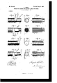
My invention relates to the exterior metallic protective portion of the cable; and it consists of the said part of the cable constructed of coiled metal strips in the manner hereinafter described, so as to be flexible and at the same time capable of tensile strength to resist being pulled apart in handling, placing, and in other ways in which it may be subject to such stresses, also so as to be nail-proof to protect the cable from nails when placed in the walls of buildings, as follows, reference being made to the accompanying drawings, in which Figure 1 is a side view of a short section of the protective portion of a cable made in accordance with my invention. Fig. 2 is an end view, and Fig. 3 is a longitudinal section, of the structure of Fig. 1. Fig. l is a side view, Fig. 5 an end View, and Fig. 6 a longitudinal section, of the structure of Fig. 1 with a section of the cable inserted. Fig. 7 is a side View, Fig. 8 an end View, and Fig. 9 a longitudinal section, of the structure of Fig. 1 without the lining of insulating material represented in Fig. 1; and Fig. 10 is a side view, Fig. 11 an end View, and Fig. 12 a longitudinal section, of the structure of Fig. 1 with a lining of lead and with an inner flatstrip coil.
The essential feature of the invention consists of one or more flat metallic strips, as a, having a row of projecting spurs or bosses, as c, on one side and along one margin and a row of recesses or indentations 1) along the other margin and on the other side wound spirally and overlapped so that the indentations cover the spurs and thus interlock the respective coils, whereby an insulating tubular protective case is provided that is flexible to permit the inclosed cable to bend freely in handling and placing and in turning angles and sinuous courses when used in buildings, and the coils will not be pulled apart nor materially disturbed by the tensile stresses to Serial No. 710.768. (No model.)
which the cable is subject. I The spurs are produced by indenting the strip in the same manner as it is indented to form the recesses; but they may be produced in any other approved way, and it is to he understood that the spurs resulting from the indentations made to produce the recesses have no function as spurs, and they only appear in the drawings as resultant of the preferred mode of producing the recesses.
The spurs will be sufficiently smaller than the recesses to allow them such lateral play in the recesses as may be desirable for the requisite flexibility of the cable.
In the drawings I have represented only one strip, coiled so as to overlap itself; but it is manifest that two or more may be coiled together, the strips being started with the recessed margin of one strip overlapping the spur margin of another.
I propose to construct the case independently of the cable when it may be desired to inclose the cable in such manner that the cable maybe drawn in and out in order that thecable may be removed for inspection and repairs without removing the casing from its fixed position. In Figs. 7, 8, and 9 such construction is represented, the casing consisting only of the metallic strip. Figs. 1, 2, and 3 show the same construction, with an insulatinglining cl, of asbestos or other suitable material, inserted, and in Figs. 10, 11, and 12 I have represented a lining of lead 6, together with an inner coiled-strip lining f, a construction better adapted for laying in water and where greater strength of the case is required.
Figs. 4, 5, and 6 representthc casing constructed on the cable g h, as when the cable is not required to be removable from the casing.
It will be seen that the overlapped coils of metallic strips make an effective nail-proof casing for protection of the cable when laid in the walls of buildings, where it is exposed to the liability of nails being driven in.
Instead of the spurs being outside and the recesses inside of the strip, as represented, they may be respectively reversed, the operation and efiect being the same.
What I claim as my invention is- 1. An electric metallic casing for electric cables, consisting of a spirally-Wound overlapped metallic strip having spurs along one margin and recesses along the other margin, said recesses overlapping said spurs.
2. An elastic metallic casing for electric cables, consisting of a spirally-Wound overlapped metallic strip having spurs along one margin and recesses along the other margin, said recesses overlapping said spurs, a lining ,for said casing and an electric cable inclosed in said lining.
3. An electric metallic casing for electric cables consisting of a spirally-Wound overlapped metallic strip having spurs along one margin and recesses along the other margin, said recesses overlapping said spurs, a lining AUGUST SUNDII. Vitnesses:
G. SEDGWICK, J. HOWARD.
Priority Applications (1)
| Application Number | Priority Date | Filing Date | Title |
|---|---|---|---|
| US71076899A US630636A (en) | 1899-03-28 | 1899-03-28 | Protective casing for electric cables or wires. |
Applications Claiming Priority (1)
| Application Number | Priority Date | Filing Date | Title |
|---|---|---|---|
| US71076899A US630636A (en) | 1899-03-28 | 1899-03-28 | Protective casing for electric cables or wires. |
Publications (1)
| Publication Number | Publication Date |
|---|---|
| US630636A true US630636A (en) | 1899-08-08 |
Family
ID=2699231
Family Applications (1)
| Application Number | Title | Priority Date | Filing Date |
|---|---|---|---|
| US71076899A Expired - Lifetime US630636A (en) | 1899-03-28 | 1899-03-28 | Protective casing for electric cables or wires. |
Country Status (1)
| Country | Link |
|---|---|
| US (1) | US630636A (en) |
Cited By (5)
| Publication number | Priority date | Publication date | Assignee | Title |
|---|---|---|---|---|
| US3093162A (en) * | 1959-06-29 | 1963-06-11 | Duriron Co | Plastic lined perforated metal tube |
| US3189676A (en) * | 1960-03-17 | 1965-06-15 | Muller Jacques | Reinforced pipes incorporating a ground wire |
| US3682203A (en) * | 1970-01-23 | 1972-08-08 | Federal Metal Hose Corp The | Flexible metal hose |
| US6155303A (en) * | 1998-05-14 | 2000-12-05 | Witzenmann Gmbh | Hose with interlocked profile, particularly for automotive exhaust systems |
| US20150274352A1 (en) * | 2012-09-26 | 2015-10-01 | Xaver Lipp | Container produced from a single-layered, helically bent sheet-metal strip |
-
1899
- 1899-03-28 US US71076899A patent/US630636A/en not_active Expired - Lifetime
Cited By (6)
| Publication number | Priority date | Publication date | Assignee | Title |
|---|---|---|---|---|
| US3093162A (en) * | 1959-06-29 | 1963-06-11 | Duriron Co | Plastic lined perforated metal tube |
| US3189676A (en) * | 1960-03-17 | 1965-06-15 | Muller Jacques | Reinforced pipes incorporating a ground wire |
| US3682203A (en) * | 1970-01-23 | 1972-08-08 | Federal Metal Hose Corp The | Flexible metal hose |
| US6155303A (en) * | 1998-05-14 | 2000-12-05 | Witzenmann Gmbh | Hose with interlocked profile, particularly for automotive exhaust systems |
| US20150274352A1 (en) * | 2012-09-26 | 2015-10-01 | Xaver Lipp | Container produced from a single-layered, helically bent sheet-metal strip |
| US10023352B2 (en) * | 2012-09-26 | 2018-07-17 | Xaver Lipp | Container produced from a single-layered, helically bent sheet-metal strip |
Similar Documents
| Publication | Publication Date | Title |
|---|---|---|
| US630636A (en) | Protective casing for electric cables or wires. | |
| US840766A (en) | Tubing. | |
| US630634A (en) | Protective casing for electric cables or wires. | |
| US479525A (en) | Frederic a | |
| US1140425A (en) | Flexible tubing. | |
| US998827A (en) | Flexible conduit. | |
| GB2057779A (en) | A flexible tubular casing for electric cable | |
| US882292A (en) | Flexible conduit. | |
| US630635A (en) | Protective casing for electric cables or wires. | |
| US2367944A (en) | Metal conduit | |
| US717778A (en) | Electric conducting-cable. | |
| US630637A (en) | Protective casing for electric cables or wires. | |
| US630599A (en) | Protective casing for electric cables or wires. | |
| US967260A (en) | Spiral metallic hose. | |
| US1164521A (en) | Protective covering or armor. | |
| US1155460A (en) | Armor for flexible articles. | |
| US1134119A (en) | Cable-armor. | |
| US1821887A (en) | Wire cable | |
| US692960A (en) | Armor or sheating for electric conductors. | |
| US577284A (en) | Conduit-sheathing | |
| US1009964A (en) | Tubing. | |
| US1275279A (en) | Conduit or conductor. | |
| US1160203A (en) | Package of elbows. | |
| US616612A (en) | Edwin t | |
| US415262A (en) | Jean a |