US6259423B1 - Display device using organic electroluminescent elements - Google Patents
Display device using organic electroluminescent elements Download PDFInfo
- Publication number
- US6259423B1 US6259423B1 US09/134,830 US13483098A US6259423B1 US 6259423 B1 US6259423 B1 US 6259423B1 US 13483098 A US13483098 A US 13483098A US 6259423 B1 US6259423 B1 US 6259423B1
- Authority
- US
- United States
- Prior art keywords
- display device
- display
- light
- panel
- luminescent
- Prior art date
- Legal status (The legal status is an assumption and is not a legal conclusion. Google has not performed a legal analysis and makes no representation as to the accuracy of the status listed.)
- Expired - Fee Related
Links
- 229910052751 metal Inorganic materials 0.000 claims abstract description 25
- 239000002184 metal Substances 0.000 claims abstract description 25
- 239000011521 glass Substances 0.000 claims abstract description 15
- 230000005525 hole transport Effects 0.000 claims abstract description 10
- 239000000758 substrate Substances 0.000 claims abstract description 6
- 239000010410 layer Substances 0.000 claims description 33
- 239000011159 matrix material Substances 0.000 claims description 14
- VYPSYNLAJGMNEJ-UHFFFAOYSA-N Silicium dioxide Chemical compound O=[Si]=O VYPSYNLAJGMNEJ-UHFFFAOYSA-N 0.000 claims description 8
- GWEVSGVZZGPLCZ-UHFFFAOYSA-N Titan oxide Chemical compound O=[Ti]=O GWEVSGVZZGPLCZ-UHFFFAOYSA-N 0.000 claims description 8
- 230000015572 biosynthetic process Effects 0.000 claims description 7
- 239000003086 colorant Substances 0.000 claims description 7
- 239000012044 organic layer Substances 0.000 claims description 7
- 229910052681 coesite Inorganic materials 0.000 claims description 4
- 229910052906 cristobalite Inorganic materials 0.000 claims description 4
- 239000000377 silicon dioxide Substances 0.000 claims description 4
- 229910052682 stishovite Inorganic materials 0.000 claims description 4
- 229910052905 tridymite Inorganic materials 0.000 claims description 4
- 230000009467 reduction Effects 0.000 abstract description 2
- 239000004973 liquid crystal related substance Substances 0.000 description 33
- 238000010586 diagram Methods 0.000 description 15
- 230000003287 optical effect Effects 0.000 description 8
- 210000003128 head Anatomy 0.000 description 5
- NRCMAYZCPIVABH-UHFFFAOYSA-N Quinacridone Chemical compound N1C2=CC=CC=C2C(=O)C2=C1C=C1C(=O)C3=CC=CC=C3NC1=C2 NRCMAYZCPIVABH-UHFFFAOYSA-N 0.000 description 4
- 230000005540 biological transmission Effects 0.000 description 4
- 238000001816 cooling Methods 0.000 description 4
- 230000020169 heat generation Effects 0.000 description 4
- 238000004020 luminiscence type Methods 0.000 description 4
- 229910052736 halogen Inorganic materials 0.000 description 3
- 150000002367 halogens Chemical class 0.000 description 3
- 239000000463 material Substances 0.000 description 3
- 238000000034 method Methods 0.000 description 3
- 230000002269 spontaneous effect Effects 0.000 description 3
- 229910052724 xenon Inorganic materials 0.000 description 3
- FHNFHKCVQCLJFQ-UHFFFAOYSA-N xenon atom Chemical compound [Xe] FHNFHKCVQCLJFQ-UHFFFAOYSA-N 0.000 description 3
- RETDKIXQRINZEF-UHFFFAOYSA-N 1,3-benzoxazole;zinc Chemical compound [Zn].C1=CC=C2OC=NC2=C1 RETDKIXQRINZEF-UHFFFAOYSA-N 0.000 description 2
- 230000009471 action Effects 0.000 description 2
- 230000007423 decrease Effects 0.000 description 2
- 230000017525 heat dissipation Effects 0.000 description 2
- 239000000203 mixture Substances 0.000 description 2
- 230000004048 modification Effects 0.000 description 2
- 238000012986 modification Methods 0.000 description 2
- DCZNSJVFOQPSRV-UHFFFAOYSA-N n,n-diphenyl-4-[4-(n-phenylanilino)phenyl]aniline Chemical class C1=CC=CC=C1N(C=1C=CC(=CC=1)C=1C=CC(=CC=1)N(C=1C=CC=CC=1)C=1C=CC=CC=1)C1=CC=CC=C1 DCZNSJVFOQPSRV-UHFFFAOYSA-N 0.000 description 2
- 230000008569 process Effects 0.000 description 2
- 206010020675 Hypermetropia Diseases 0.000 description 1
- 230000004075 alteration Effects 0.000 description 1
- 230000003321 amplification Effects 0.000 description 1
- 238000006243 chemical reaction Methods 0.000 description 1
- 230000000694 effects Effects 0.000 description 1
- 238000000295 emission spectrum Methods 0.000 description 1
- 238000005265 energy consumption Methods 0.000 description 1
- 239000003269 fluorescent indicator Substances 0.000 description 1
- 230000003760 hair shine Effects 0.000 description 1
- AMGQUBHHOARCQH-UHFFFAOYSA-N indium;oxotin Chemical compound [In].[Sn]=O AMGQUBHHOARCQH-UHFFFAOYSA-N 0.000 description 1
- 238000001755 magnetron sputter deposition Methods 0.000 description 1
- 238000004519 manufacturing process Methods 0.000 description 1
- 229910001507 metal halide Inorganic materials 0.000 description 1
- 150000005309 metal halides Chemical class 0.000 description 1
- 238000003199 nucleic acid amplification method Methods 0.000 description 1
- 239000011347 resin Substances 0.000 description 1
- 229920005989 resin Polymers 0.000 description 1
- 238000005549 size reduction Methods 0.000 description 1
- 230000003595 spectral effect Effects 0.000 description 1
- 238000001228 spectrum Methods 0.000 description 1
- 238000002834 transmittance Methods 0.000 description 1
- 238000007738 vacuum evaporation Methods 0.000 description 1
- 238000001039 wet etching Methods 0.000 description 1
Images


Classifications
-
- H—ELECTRICITY
- H10—SEMICONDUCTOR DEVICES; ELECTRIC SOLID-STATE DEVICES NOT OTHERWISE PROVIDED FOR
- H10K—ORGANIC ELECTRIC SOLID-STATE DEVICES
- H10K50/00—Organic light-emitting devices
- H10K50/80—Constructional details
- H10K50/85—Arrangements for extracting light from the devices
- H10K50/852—Arrangements for extracting light from the devices comprising a resonant cavity structure, e.g. Bragg reflector pair
-
- H—ELECTRICITY
- H04—ELECTRIC COMMUNICATION TECHNIQUE
- H04N—PICTORIAL COMMUNICATION, e.g. TELEVISION
- H04N9/00—Details of colour television systems
- H04N9/12—Picture reproducers
- H04N9/31—Projection devices for colour picture display, e.g. using electronic spatial light modulators [ESLM]
- H04N9/3138—Projection devices for colour picture display, e.g. using electronic spatial light modulators [ESLM] using arrays of modulated light sources
-
- H—ELECTRICITY
- H10—SEMICONDUCTOR DEVICES; ELECTRIC SOLID-STATE DEVICES NOT OTHERWISE PROVIDED FOR
- H10K—ORGANIC ELECTRIC SOLID-STATE DEVICES
- H10K59/00—Integrated devices, or assemblies of multiple devices, comprising at least one organic light-emitting element covered by group H10K50/00
- H10K59/10—OLED displays
- H10K59/17—Passive-matrix OLED displays
-
- H—ELECTRICITY
- H10—SEMICONDUCTOR DEVICES; ELECTRIC SOLID-STATE DEVICES NOT OTHERWISE PROVIDED FOR
- H10K—ORGANIC ELECTRIC SOLID-STATE DEVICES
- H10K59/00—Integrated devices, or assemblies of multiple devices, comprising at least one organic light-emitting element covered by group H10K50/00
- H10K59/80—Constructional details
- H10K59/875—Arrangements for extracting light from the devices
- H10K59/876—Arrangements for extracting light from the devices comprising a resonant cavity structure, e.g. Bragg reflector pair
-
- H—ELECTRICITY
- H10—SEMICONDUCTOR DEVICES; ELECTRIC SOLID-STATE DEVICES NOT OTHERWISE PROVIDED FOR
- H10K—ORGANIC ELECTRIC SOLID-STATE DEVICES
- H10K59/00—Integrated devices, or assemblies of multiple devices, comprising at least one organic light-emitting element covered by group H10K50/00
- H10K59/90—Assemblies of multiple devices comprising at least one organic light-emitting element
- H10K59/95—Assemblies of multiple devices comprising at least one organic light-emitting element wherein all light-emitting elements are organic, e.g. assembled OLED displays
-
- G—PHYSICS
- G09—EDUCATION; CRYPTOGRAPHY; DISPLAY; ADVERTISING; SEALS
- G09G—ARRANGEMENTS OR CIRCUITS FOR CONTROL OF INDICATING DEVICES USING STATIC MEANS TO PRESENT VARIABLE INFORMATION
- G09G3/00—Control arrangements or circuits, of interest only in connection with visual indicators other than cathode-ray tubes
- G09G3/20—Control arrangements or circuits, of interest only in connection with visual indicators other than cathode-ray tubes for presentation of an assembly of a number of characters, e.g. a page, by composing the assembly by combination of individual elements arranged in a matrix no fixed position being assigned to or needed to be assigned to the individual characters or partial characters
- G09G3/22—Control arrangements or circuits, of interest only in connection with visual indicators other than cathode-ray tubes for presentation of an assembly of a number of characters, e.g. a page, by composing the assembly by combination of individual elements arranged in a matrix no fixed position being assigned to or needed to be assigned to the individual characters or partial characters using controlled light sources
- G09G3/30—Control arrangements or circuits, of interest only in connection with visual indicators other than cathode-ray tubes for presentation of an assembly of a number of characters, e.g. a page, by composing the assembly by combination of individual elements arranged in a matrix no fixed position being assigned to or needed to be assigned to the individual characters or partial characters using controlled light sources using electroluminescent panels
- G09G3/32—Control arrangements or circuits, of interest only in connection with visual indicators other than cathode-ray tubes for presentation of an assembly of a number of characters, e.g. a page, by composing the assembly by combination of individual elements arranged in a matrix no fixed position being assigned to or needed to be assigned to the individual characters or partial characters using controlled light sources using electroluminescent panels semiconductive, e.g. using light-emitting diodes [LED]
- G09G3/3208—Control arrangements or circuits, of interest only in connection with visual indicators other than cathode-ray tubes for presentation of an assembly of a number of characters, e.g. a page, by composing the assembly by combination of individual elements arranged in a matrix no fixed position being assigned to or needed to be assigned to the individual characters or partial characters using controlled light sources using electroluminescent panels semiconductive, e.g. using light-emitting diodes [LED] organic, e.g. using organic light-emitting diodes [OLED]
- G09G3/3216—Control arrangements or circuits, of interest only in connection with visual indicators other than cathode-ray tubes for presentation of an assembly of a number of characters, e.g. a page, by composing the assembly by combination of individual elements arranged in a matrix no fixed position being assigned to or needed to be assigned to the individual characters or partial characters using controlled light sources using electroluminescent panels semiconductive, e.g. using light-emitting diodes [LED] organic, e.g. using organic light-emitting diodes [OLED] using a passive matrix
-
- H—ELECTRICITY
- H01—ELECTRIC ELEMENTS
- H01L—SEMICONDUCTOR DEVICES NOT COVERED BY CLASS H10
- H01L2924/00—Indexing scheme for arrangements or methods for connecting or disconnecting semiconductor or solid-state bodies as covered by H01L24/00
- H01L2924/0001—Technical content checked by a classifier
- H01L2924/0002—Not covered by any one of groups H01L24/00, H01L24/00 and H01L2224/00
-
- H—ELECTRICITY
- H10—SEMICONDUCTOR DEVICES; ELECTRIC SOLID-STATE DEVICES NOT OTHERWISE PROVIDED FOR
- H10K—ORGANIC ELECTRIC SOLID-STATE DEVICES
- H10K50/00—Organic light-emitting devices
- H10K50/80—Constructional details
- H10K50/85—Arrangements for extracting light from the devices
- H10K50/858—Arrangements for extracting light from the devices comprising refractive means, e.g. lenses
-
- H—ELECTRICITY
- H10—SEMICONDUCTOR DEVICES; ELECTRIC SOLID-STATE DEVICES NOT OTHERWISE PROVIDED FOR
- H10K—ORGANIC ELECTRIC SOLID-STATE DEVICES
- H10K50/00—Organic light-emitting devices
- H10K50/80—Constructional details
- H10K50/87—Arrangements for heating or cooling
-
- H—ELECTRICITY
- H10—SEMICONDUCTOR DEVICES; ELECTRIC SOLID-STATE DEVICES NOT OTHERWISE PROVIDED FOR
- H10K—ORGANIC ELECTRIC SOLID-STATE DEVICES
- H10K59/00—Integrated devices, or assemblies of multiple devices, comprising at least one organic light-emitting element covered by group H10K50/00
- H10K59/30—Devices specially adapted for multicolour light emission
- H10K59/35—Devices specially adapted for multicolour light emission comprising red-green-blue [RGB] subpixels
-
- H—ELECTRICITY
- H10—SEMICONDUCTOR DEVICES; ELECTRIC SOLID-STATE DEVICES NOT OTHERWISE PROVIDED FOR
- H10K—ORGANIC ELECTRIC SOLID-STATE DEVICES
- H10K59/00—Integrated devices, or assemblies of multiple devices, comprising at least one organic light-emitting element covered by group H10K50/00
- H10K59/80—Constructional details
- H10K59/875—Arrangements for extracting light from the devices
- H10K59/879—Arrangements for extracting light from the devices comprising refractive means, e.g. lenses
-
- H—ELECTRICITY
- H10—SEMICONDUCTOR DEVICES; ELECTRIC SOLID-STATE DEVICES NOT OTHERWISE PROVIDED FOR
- H10K—ORGANIC ELECTRIC SOLID-STATE DEVICES
- H10K59/00—Integrated devices, or assemblies of multiple devices, comprising at least one organic light-emitting element covered by group H10K50/00
- H10K59/80—Constructional details
- H10K59/8794—Arrangements for heating and cooling
Definitions
- the present invention relates to a display device using organic electroluminescent (EL) elements.
- EL organic electroluminescent
- Various types of display devices are known, one of which is a projector type display.
- This projector type display normally uses a liquid crystal panel. More specifically, a transmitted light is obtained by controlling each liquid crystal element of the liquid crystal panel according to video information and also by controlling the transmitted light by using a polarizing plate. Then, by projecting the transmitted light controlled according to the video information onto a screen, a video image is displayed.
- FIG. 11 shows an example of the conventional full-color projector type display.
- a reflector 104 is disposed behind a light source 102 , with the result that a parallel beam of white light is emitted forward.
- the parallel beam is first reflected by a mirror 106 and is then incident on a dichroic mirror 108 , which is arranged tilted 45° from the optical path, and only yellow light is reflected by the mirror 108 in a direction at right angles with the optical path before reflection. Therefore, the transmitted light of the mirror 108 is red light. This red light is reflected in a specified direction by a mirror 110 .
- Liquid crystal panels 120 , 122 and 124 are disposed close to the three sides of a dichroic lens 126 and accept red light, green light and blue light, respectively.
- the liquid crystal panels 120 , 122 and 124 cause the red, green and blue light, modulated by the control of the liquid crystals, to fall on the dichroic lens 126 .
- the dichroic lens 126 combines those rays that go into the above-mentioned three sides to form a parallel beam, which is emitted from the one other side.
- a screen 130 is installed across a lens 128 in front of the one other side of the dichroic lens 126 .
- the red, green and blue rays, which have been modulated separately by the liquid crystal panels 120 , 122 and 124 , are combined, and a full-color image is displayed on the screen 130 .
- HUD head up displays
- the projector type display devices are audio-visual displays to show a TV screen or the like and head up displays (HUD) used in automobiles or airplanes.
- HUD head up displays
- light rays that have passed through the liquid crystal panel are projected by means of a dichroic filter or a hologram optical element.
- FIG. 12 shows an example of the structure of a conventional dichroic system HUD.
- a light source 140 formed by a halogen lamp (or a xenon lamp)
- a liquid crystal panel 142 In front of a light source 140 formed by a halogen lamp (or a xenon lamp), there is a liquid crystal panel 142 .
- a transmitted light of the liquid crystal panel 142 passes through a shutter 144 , a mirror 146 and a collimating lens 148 , and is applied to a dichroic filter 150 attached to the inner surface of the windshield glass.
- a virtual image of an image modulated by the liquid crystal panel 142 appears in front of the windshield glass.
- FIG. 13 shows an example of the conventional hologram system HUD.
- a light from a light source 160 formed by a halogen lamp (or a xenon lamp) or a CRT (cathode ray tube) is injected into a liquid crystal panel 162 that includes a polarizing plate.
- the light, modulated by the liquid crystal panel 162 passes through an aberration-corrected lens system 164 and a mirror 166 , and is projected onto a hologram optical element (a diffraction grating) 168 provided on the windshield glass. Accordingly, a virtual image of an image formed in the liquid crystal panel 162 is made to appear in front of the windshield glass.
- a hologram optical element a diffraction grating
- the liquid crystal display In the area of devices for information display, there are CRT, the liquid crystal display, the plasma display, the inorganic EL display and so on.
- these kinds of displays are designed to provide a wide angle of field, and make it possible for the viewers to look at the displayed information from a diagonal direction.
- the angle of field it is desired that the angle of field be limited.
- the liquid crystal displays which are not spontaneous luminescent type displays, the angle of field can be narrowed easily, but there is a problem that it is difficult to achieve an image display with high luminance.
- the liquid crystal display device was not preferable.
- a display device comprises a luminescent panel (organic EL panel) having organic electroluminescent elements (organic EL elements) arranged in a matrix, and a driver for driving the individual organic EL elements of the luminescent panel on the basis of video information.
- a luminescent panel organic EL panel
- organic electroluminescent elements organic EL elements
- the luminescent panel is formed by arranging the organic EL elements in a matrix formation. Therefore, an image can be displayed according to video information, that is, by causing desired organic EL elements to emit light. Being spontaneous luminescence elements, the organic EL elements do not require a light source.
- the organic EL panel which generates light according to video information, does not require a transmission type liquid crystal panel or the like, and therefore the generated light can be utilized one hundred percent. As a result, the organic EL panel can make a high-luminance image display with ease.
- the display device according to the present invention can be formed in a simple structure, and can be produced in a smaller size and with a lighter weight easily.
- Suitable for this organic EL panel is a micro-optical resonance type organic EL element disclosed in Japanese Patent Laid-Open Publication No. Hei-9-180883.
- an organic EL element such as this, it is possible to obtain light with high luminance, high directivity and better monochromaticity. It also becomes possible to easily display an image with a high luminance of 10000 cd/m 2 .
- An organic EL element such as this is formed by stacking a dielectric mirror, a transparent electrode, a hole transport layer, a luminous layer, and a metal electrode on a glass substrate.
- a dielectric mirror By placing the transparent electrodes and the metal electrodes so that their stripes perpendicularly intersect each other, the pixels can be arranged at the intersections of those electrodes in a matrix formation. Accordingly, a display device with a simple matrix type drive can be realized by controlling the application of a voltage between the transparent electrodes and the metal electrodes.
- the light from the organic EL panel is preferably projected through a projection lens to a screen. Being free from power attenuation during transmission through the liquid crystal or the polarizing plate, the present invention can realize a high-luminance projector type display.
- three matrix type organic EL panels for different luminescent colors are provided, the light emission of those panels is controlled according to information, and the rays of different colors are combined and projected onto a screen.
- the three organic EL panels By allotting the three organic EL panels to the three primary colors (R, G and B), a full color image can be displayed on the screen.
- the light from the light source must be separated by dichroic mirrors, for example, into primaries R, G and B, so that the device necessarily becomes large in size.
- dichroic mirrors are very expensive.
- the liquid crystal is required to have a large contrast ratio (100:1 to 1000:1).
- the luminance of the light source is required to be 10000 cd/m 2 or higher.
- the organic EL panels generate primaries R, G and B with high directivity, respectively, so that the structure of the device is simple and the optical system can be obviated. Furthermore, the organic EL panel can produce a high luminance, for which reason a distinct image can be obtained easily, and not many problems, such as heat generation, will be encountered.
- the light including video information, which is generated by the organic EL panel is utilized in the head up displays.
- the head up displays particularly those attached to the windshield glass of vehicles, a sufficient visibility of information displayed must be secured without sacrificing the visibility of the view in front of the car, and a light source for very high luminance of the screen is required.
- the luminance of the xenon lamp is 3000 cd/m 2 and its service life is about 100 hours.
- a light source should desirably have a life of 10000 hours when used at a luminance of 10000 ⁇ 15000 cd/m 2 , but such a light source has yet to be developed.
- a Fresnel lens or the like is used, because of its low light transmittance and the no directivity of the emitted light, there is a great loss of light.
- the organic EL panel With the organic EL panel, since the panel generates light by itself, the produced light can be utilized one hundred percent. Therefore, the organic EL panel can perform display with high luminance while keeping light loss a minimum level.
- the display can be structured in a simple form, thus offering chances of reductions in size and weight.
- the essential requirement of the display is a compact size, and to this end, it is most desirable to use the organic EL panel. Be it a dichroic system or a hologram system, an organic EL panel can preferably be used.
- the organic EL panel should preferably be used as is to achieve a high-directivity display.
- the micro-optical resonance type organic EL element has high directivity. Therefore, an organic EL panel using those organic EL elements provides better visibility to the viewer who squarely faces the panel, but the visibility decreases sharply when the viewer shifts to either side.
- the visibility should be secured only for the driver, so that this type of display should preferably be used.
- the organic EL panel images can be displayed with a high luminance of 10000 cd/m 2 or higher, as the result, the driver can easily view the displayed information when the sun is shining in through the window or the driver is an elderly person.
- FIG. 1 is a diagram showing the structure of the organic EL panel
- FIG. 2 is a perspective view showing the structure of the organic EL panel
- FIG. 3 is a diagram showing a luminescence pattern
- FIG. 4 is a block diagram showing the general composition of the display, including driver circuits
- FIG. 5 is a diagram showing the structure of a mono-color display
- FIG. 6 is a diagram showing the composition of a full-color display
- FIGS. 7 a , 7 b and 7 c are diagrams showing wavelengths of luminescence
- FIG. 8 is a diagram showing the structure of a hologram system HUD
- FIG. 9 is a diagram showing the structure of a dichroic system HUD.
- FIG. 10 is a diagram showing the arrangement of a direct viewing type display
- FIG. 11 is a diagram showing the structure of a conventional full-color display
- FIG. 12 is a diagram showing the structure of a conventional dichroic system HUD.
- FIG. 13 is a diagram showing the structure of a conventional hologram system HUD
- FIGS. 14A and 14B are diagrams showing a structure that enables a full-color display by a single luminescent panel.
- FIG. 1 is a diagram showing the structure of an example of an organic EL panel according to a preferred embodiment of the present invention.
- the basic structure of a piece of electroluminescent element is the same as in Japanese Patent Laid-Open Publication No. Hei-9-180883.
- This element is organized by forming a dielectric mirror 12 , a transparent electrode 14 , a hole transport layer 16 , a luminous layer 18 , and a metal electrode 20 in this order on a glass substrate.
- the glass substrate 10 is in a rectangular form with two 2.5-inch diagonal lines.
- the dielectric mirror 12 is obtained by alternately forming a SiO 2 layer and a TiO 2 layer. Each layer of SiO 2 and TiO 2 of the dielectric layer 12 is determined so as to be 1 ⁇ 4 of a 580-nm wavelength of the center frequency of the stop band.
- the transparent electrode 14 is formed of ITO (indium tin oxide), and the space between the metal mirror and the dielectric mirror is set at about 1 ⁇ 2 of or about the same as the wavelength of light that is made to resonate. In this example, the thickness of the transparent electrode 14 is 40 nm.
- a triphenyldiamine derivative is used, and its thickness is set at 55 nm.
- an alumiquinolinol complex is used, and its thickness is set at 40 nm.
- This luminous layer 18 is doped with about 1% quinacridone in order to improve luminous efficiency.
- the thickness of an organic layer consisting of the hole transport layer 16 and the luminous layer 18 is set such that the resonance wavelength becomes a wavelength of 535 nm, which is close to a peak on the short wavelength side of the emission spectrum of quinacridone to prevent other resonance wavelengths from occurring in the spectrum of quinacridone.
- MgAg is used for the metal electrode 20 .
- the organic EL panel according to the present embodiment includes the transparent electrodes 14 and the metal electrodes arranged so as to intersect each other as shown in FIG. 2, and the organic EL elements are located at the intersections of the two kinds of electrodes. More specifically, the organic EL panel is a simple matrix type panel, which includes 20 horizontal lines of the 2-mm-wide transparent electrodes 14 and 30 vertical lines of the 2-mm-wide metal electrodes 20 .
- This organic EL panel is formed as follows.
- the dielectric mirror 12 and the transparent electrode 14 are deposited by the RF magnetron sputtering process.
- the transparent electrode 14 is etched so as to be in stripes by wet etching.
- the hole transport layer 16 and the luminous layer 18 and the metal electrode 20 are deposited in this order by the vacuum evaporation process.
- the metal electrode 20 is formed in stripes by using a mechanical mask.
- the organic EL panel is encapsulated by a glass plate and a ultraviolet cured resin. If necessary, the panel may be fitted on its rear side with a radiator plate or a cooling fan to restrain the temperature rise of the panel.
- the dielectric mirror 12 and the metal electrode 20 constitute a micro-optical resonator.
- This micro-optical resonator causes resonance of a ray of a specific wavelength among the rays output from the organic layer made of the hole transport layer 16 and the luminous layer 18 , and this ray is radiated with high directivity in the direction of the front face of the panel.
- FIG. 3 is a schematic diagram of the emission pattern. As depicted, a ray with high directivity is emitted in the direction of the front face.
- a high-luminance panel can be realized.
- the above-mentioned structure is an example, and thus for the materials of the layers of the organic EL panel, various kinds of materials described in Japanese Patent Laid-Open Publication No. Hei-9-180883 may be adopted. The material and the thickness are varied with different kinds of luminescent color.
- FIG. 4 shows an example of the structure of the organic luminescent panel, which also shows driver circuits.
- Two booster circuits 32 , 34 are connected to a 4.5V DC power source 30 .
- the booster circuit 32 can output voltages in the range of 5V to 12V.
- the output voltage of this booster circuit 32 is supplied to a driver 36 .
- the booster circuit 34 outputs a constant voltage of 5V.
- the output voltage of the booster circuit 34 is supplied as a source voltage to a microcomputer 38 .
- the microcomputer 38 comprises an I/O interface 38 a for exchange of signals with outside devices, a ROM 38 b for storing programs, a RAM 38 c for storing various items of data, and a CPU 38 d for performing various operations.
- a clock generator circuit 40 connected to the microcomputer 38 , supplies clock signals to set timing of actions at a frequency of 8 MHz.
- Two oscillators 42 , 44 are connected to the microcomputer 38 .
- the oscillator 42 supplies signals of 5 MHz to 50 MHz to control displaying speed, and the oscillator 44 supplies signals of 0.2 kHz to 2 kHz to control scanning frequency.
- An organic EL panel 48 is connected through two drivers to the microcomputer 38 .
- the driver 36 is a circuit to control whether or not to apply a voltage, supplied from the booster circuit 32 as described above, to the organic EL panel, and is formed of transistors respectively connected to the vertical electrodes in the organic EL panel 48 .
- a transistor in the driver 36 is turned on, a voltage from the booster circuit 32 is applied to a vertical electrode connected to this transistor.
- the driver 46 is formed of transistors respectively connected to the horizontal electrodes in the organic EL panel 48 . When a transistor in the driver 46 is turned on, a horizontal electrode connected to this transistor is connected to earth.
- the microcomputer 38 controls the drivers 36 and 46 to turn on one transistor each, voltage is applied across one vertical electrode and one horizontal electrode, with the result that an organic EL element at the intersection of the two electrodes emits light. Therefore, when one horizontal line is selected by a transistor of the driver 46 and under this condition the driver 36 turns on the transistors specified by data for that line, the display of data is effected at the pixels of one horizontal line. By repeating this scanning action in the vertical direction, the display of one picture can be achieved.
- the horizontal driver 36 is provided with a data register for one line to thereby drive the transistors according to stored data.
- Video data for display may be supplied externally in step with the internal display cycle. Prearranged patterns of characters or the like may be stored in ROM 38 B and displayed.
- a video signal is sent at horizontal and vertical scanning frequencies specified by a standard.
- the horizontal and vertical synchronizing signals are separated from the video signal, and the video component is converted into digital signals corresponding to the number of pixels of the organic EL panel.
- the video signal is displayed on the organic EL panel 48 in step with the horizontal and vertical synchronizing signals.
- FIG. 5 shows an example of a projector type display utilizing the above-mentioned organic EL panel 48 .
- a mono-color display is performed.
- a projection lens 50 is placed in front of the organic EL panel 48 .
- a screen 52 is set.
- a displayed image on the organic EL panel 48 is magnified by the projection lens 50 , and brought to a focus on the screen 52 .
- the image on the organic EL panel 48 is projected onto the screen 52 .
- the radiator plate 54 is used to dissipate the heat of the organic EL panel 48 .
- characters were displayed by driving the organic EL panel 48 with a matrix of 30 horizontal lines ⁇ 20 vertical lines, a duty ratio of ⁇ fraction (1/32) ⁇ , and a voltage of 15V.
- the luminescent color was green with better monochromaticity
- the luminance on the organic EL panel 48 was 10000 cd/m 2
- the luminance on the screen 52 was 200 cd/m 2
- a distinct image was projected on the screen 52 .
- the organic EL panel emits light by itself, and also serves as information conversion means for converting video information into light. Therefore, the organic EL panel 48 performs two functions as a light source in a projector type display that uses a liquid crystal panel, and also as a liquid crystal panel. Accordingly, the organic EL panel 48 is very simple in structure. Since the organic EL panel 48 emits light spontaneously, there is no light loss that would occur when light is passed through a liquid crystal panel or a polarizing plate, for which reason the light utilization factor is high. Thus, it is easy to produce bright images, and heat generation is relatively low. On the flat organic EL panel 48 , a radiator plate or the like can be installed easily and will exhibit great cooling efficiency. Therefore, the display device can be reduced in size and weight by simplifying the general configuration of the device, and therefore clear images can be produced.
- a reflection type screen or a transmission type screen can be applied.
- the screen can be used also for a display device on a vehicle with a limited display area.
- FIG. 6 shows a full-color projection type display. As illustrated, this display uses three organic EL panels 48 R, 48 G and 48 B for red, green and blue rays. Those three organic EL panels 48 R, 48 G and 48 B are arranged close to the three sides of a dichroic prism 56 . A projection lens 50 is arranged in front of the one other side of the dichroic prism 56 . A screen 52 is disposed further ahead of the projection lens 50 .
- the dichroic prism 56 combines the rays coming in from the three sides, and emits the rays toward the projection lens 50 . Therefore, the rays generated in the three organic EL panels 48 R, 48 G and 48 B are combined to form a full-color picture on the screen 52 .
- the three organic EL panels 48 R, 48 G and 48 B may be driven according to display data of R, G and B colors.
- the organic EL panel 48 G for green light may be structured as described above.
- the organic EL panel 48 B for blue light may be formed by making the luminous layer of a benzoxazole zinc complex and setting the resonance wavelength at 450 nm.
- the organic EL panel 48 R for red light may be realized by forming the luminous layer of DCM and setting the resonance wavelength at 610 nm.
- the structures of a benzoxazole zinc complex and DCM are shown below.
- the number of layers and the reflectance of the dielectric mirror 12 can be varied, with the result that the spectral half-width of an emission wavelength (corresponding to color purity) and the degree of light amplification can be controlled. Furthermore, fine adjustment of an emission wavelength is possible by varying a resonance wavelength.
- each luminescent color can be made to have better monochromaticity than the luminescent color from the organic layer as shown in FIGS. 7 a , 7 b and 7 c .
- the degree of monochromaticity can be varied. Therefore, the luminescent color can be selected to suit the purpose of use or the user. By this method, a full-color display can be adjusted finely. Note that the adjustment of a luminescent color can also be done on a mono-color display.
- the display structure is very simple and can be made in a compact form.
- a projector type display using a liquid crystal panel requires a complicated optical system to generate R, G and B rays.
- the organic EL panel being capable of emitting R, G and B rays by itself, does not require such a complicated optical system at all. Being free from the problem of attenuation as in light transmission through a liquid crystal or a polarizing plate, the organic EL panel can produce images with high luminance.
- the organic EL panels 48 R, 48 G and 48 B for R, G and B color are provided separately, but they can be incorporated in a single panel. More specifically, as shown in FIGS. 14A and 14B, by arranging the organic EL elements of primary colors successively and in a matrix formation and making the R, G and B pixels emit light according to video signals, a full-color display on a single organic EL panel can be achieved.
- the general structure of the device is the same as in the mono-color display shown in FIG. 5, in other words, a single organic EL panel 48 can effect a full-color display.
- FIG. 8 shows a structural example of a hologram system head up display (HUD) mounted on a vehicle.
- HUD head up display
- two mirrors 60 and 62 are arranged in front of an organic EL panel 48 to thereby control the direction of light output by emission of the organic EL panel 48 .
- This light strikes a holographic lens 64 , by which the light is reflected.
- the reflected light is applied to a combiner 66 attached to the inner surface of the windshield glass.
- a virtual image appears to be in front of the windshield glass, which corresponds to an image displayed on the organic EL panel 48 .
- a virtual image should be formed about 2 m ahead of the windshield glass.
- the organic EL panel 48 not much heat is generated because the organic EL panel 48 emits light by itself, and heat can be dissipated relatively easily because the organic EL panel 48 is flat in shape. Its structure is simpler than in a type of device that has a light source and a liquid crystal panel provided separately. Therefore, the general device structure can be made in a compact form. In an application as a full-color display, because of its very simple structure, it can be preferably mounted on a vehicle.
- FIG. 9 shows a structural example of a dichroic system head up display (HUD) mounted on a vehicle.
- a mirror 70 is arranged in front of an organic EL display 48 , and the light reflected from the mirror 70 passes through a collimating lens 72 , and is applied to a dichroic filter 74 attached to the inner surface of the windshield. Therefore, a virtual image of an image of the organic EL panel 48 appears to be ahead of the windshield.
- a shutter 76 is provided to prevent a reverse convergence of sunlight by the collimating lens 72 . Even in this structure, as in the hologram system HUD mentioned above, a compact-size device can be produced and cooling can be facilitated.
- the projector type display has been described.
- the organic EL panel 48 performs display by spontaneous luminescence, this panel can be used as a direct-viewing display.
- the organic EL panel 48 has a resonator portion including the dielectric mirror 12 and the metal electrode 20 . Therefore, light with high directivity is emitted in the direction of the front face of the organic EL panel 48 . For this reason, it is possible to provide a display which features high visibility with high luminance for a viewer in front of the screen but has lower visibility for viewing from other directions.
- the organic EL panel 48 shown in FIG. 10 characters were displayed with a duty ratio of ⁇ fraction (1/32) ⁇ and a voltage of 10V.
- the luminance was 500 cd/m 2 .
- a display of green color with better monochromaticity could be confirmed.
- the luminance was 50 cd/m 2 , and a displayed image was indistinct.
- the luminance at the front face was about 200 cd/m 2 , and a displayed image was visible also from a diagonal direction. The color purity was worse than in the present embodiment.
- a high-directivity display such as this can be preferably used for an onboard display, an instrument panel display for example.
- an onboard display an instrument panel display for example.
- FIG. 10 by installing a display so that it is distinct and highly visible only to a driver sitting correctly in the driver's seat, the driver can be made conscious of safe driving in a correct posture.
- a high-luminance image display is possible at 500 cd/m 2 or higher. This bright display serves to make a farsighted elderly driver narrow his or her eyes unconsciously. Narrowing the eyes reduces chromatic aberration and helps the driver see a sharp image of display on the instrument panel nearby, that is to say, display becomes more easily visible. Also, because a sufficient luminance is obtainable, a secure display can be effected even when the sun shines through the window.
Landscapes
- Engineering & Computer Science (AREA)
- Multimedia (AREA)
- Signal Processing (AREA)
- Physics & Mathematics (AREA)
- Optics & Photonics (AREA)
- Electroluminescent Light Sources (AREA)
- Devices For Indicating Variable Information By Combining Individual Elements (AREA)
Abstract
For use in a display device, a simple-matrix-drive-type luminescent panel is formed by stacking a dielectric mirror layer, a transparent electrode, a hole transport layer, a luminous layer, and a metal electrode on a glass substrate, wherein the transparent electrode is formed as a plurality of stripes equally spaced apart a specified distance from each other, and the metal electrode is formed as a plurality of stripes equally spaced apart a specified distance from each other and arranged at right angles with the transparent electrode stripes, and pixels are formed at intersections of the metal electrodes and the transparent electrodes and wherein in order for the pixels of the panel to emit light to display information, the application of a voltage to the pixels is controlled by selection of the electrodes according to information. This luminescent panel contributes to reductions in size and weight of the display device.
Description
1. Field of the Invention
The present invention relates to a display device using organic electroluminescent (EL) elements.
2. Description of the Related Art
Various types of display devices are known, one of which is a projector type display. This projector type display normally uses a liquid crystal panel. More specifically, a transmitted light is obtained by controlling each liquid crystal element of the liquid crystal panel according to video information and also by controlling the transmitted light by using a polarizing plate. Then, by projecting the transmitted light controlled according to the video information onto a screen, a video image is displayed.
FIG. 11 shows an example of the conventional full-color projector type display. As illustrated, a reflector 104 is disposed behind a light source 102, with the result that a parallel beam of white light is emitted forward. The parallel beam is first reflected by a mirror 106 and is then incident on a dichroic mirror 108, which is arranged tilted 45° from the optical path, and only yellow light is reflected by the mirror 108 in a direction at right angles with the optical path before reflection. Therefore, the transmitted light of the mirror 108 is red light. This red light is reflected in a specified direction by a mirror 110. When the yellow light reflected by the dichroic mirror 108 is incident on a dichroic mirror 112, green light is separated and reflected in a right-angle direction, and blue light passes through the mirror 112. The blue light reflects through mirrors 114 and 116 and goes on to a specified direction. Liquid crystal panels 120, 122 and 124, each including a polarizing plate, are disposed close to the three sides of a dichroic lens 126 and accept red light, green light and blue light, respectively. The liquid crystal panels 120, 122 and 124 cause the red, green and blue light, modulated by the control of the liquid crystals, to fall on the dichroic lens 126. The dichroic lens 126 combines those rays that go into the above-mentioned three sides to form a parallel beam, which is emitted from the one other side. A screen 130 is installed across a lens 128 in front of the one other side of the dichroic lens 126. The red, green and blue rays, which have been modulated separately by the liquid crystal panels 120, 122 and 124, are combined, and a full-color image is displayed on the screen 130.
Among the projector type display devices are audio-visual displays to show a TV screen or the like and head up displays (HUD) used in automobiles or airplanes. In the HUD, light rays that have passed through the liquid crystal panel are projected by means of a dichroic filter or a hologram optical element.
FIG. 12 shows an example of the structure of a conventional dichroic system HUD. In front of a light source 140 formed by a halogen lamp (or a xenon lamp), there is a liquid crystal panel 142. A transmitted light of the liquid crystal panel 142 passes through a shutter 144, a mirror 146 and a collimating lens 148, and is applied to a dichroic filter 150 attached to the inner surface of the windshield glass. Thus, a virtual image of an image modulated by the liquid crystal panel 142 appears in front of the windshield glass.
FIG. 13 shows an example of the conventional hologram system HUD. A light from a light source 160 formed by a halogen lamp (or a xenon lamp) or a CRT (cathode ray tube) is injected into a liquid crystal panel 162 that includes a polarizing plate. The light, modulated by the liquid crystal panel 162, passes through an aberration-corrected lens system 164 and a mirror 166, and is projected onto a hologram optical element (a diffraction grating) 168 provided on the windshield glass. Accordingly, a virtual image of an image formed in the liquid crystal panel 162 is made to appear in front of the windshield glass.
Incidentally, in the display mentioned above, light loses its power greatly when it passes through the liquid crystal panel. To produce color images, three primaries are generated from white light emitted from a light source, and the rays of three primaries are transmitted through the three liquid crystal panels, respectively. In this case, the utilization factor of light is 10% or so. Therefore, to produce bright images, it is required to irradiate the liquid crystal panel with light at a high luminance of about 10000 cd/m2. Normally, a metal halide lamp or a halogen lamp is used as the light source. A high voltage needs to be used for the light source, and in this case, there is a problem that high heat is generated by the light source. To obtain an adequate transmitted light, it is necessary to irradiate the liquid crystal panel with light with sufficient parallelism. To this end, it is necessary to provide the light source with a large reflector, which is a hindrance to the movement toward weight and size reductions of the device itself. Another problem is the need to provide a large cooling fan for the light source.
With regard to the HUD in automobiles or airplanes, there are requirements to decrease the size, weight and energy consumption. Those problems with the projector type display have been obstacles to the widespread use of HUD.
In the area of devices for information display, there are CRT, the liquid crystal display, the plasma display, the inorganic EL display and so on. However, these kinds of displays are designed to provide a wide angle of field, and make it possible for the viewers to look at the displayed information from a diagonal direction. On the other hand, with some displays, it is desired that the angle of field be limited. In the liquid crystal displays, which are not spontaneous luminescent type displays, the angle of field can be narrowed easily, but there is a problem that it is difficult to achieve an image display with high luminance. With display on the instrument panel of a car, it is required that an information display should be visible to the driver only and that high luminance should be provided to secure enough visibility even when there is direct sunlight coming into the car. Therefore, in view of the above requirements, the liquid crystal display device was not preferable. There are displays that use LED or a fluorescent indicator tube (a magic eye), but they are only capable of simple display, and are not suitable for display with high resolution.
It is an object of the present invention to provide a display device simple in structure and easy to reduce the size and weight.
According to the present invention, a display device comprises a luminescent panel (organic EL panel) having organic electroluminescent elements (organic EL elements) arranged in a matrix, and a driver for driving the individual organic EL elements of the luminescent panel on the basis of video information.
As described above, in the present invention, the luminescent panel is formed by arranging the organic EL elements in a matrix formation. Therefore, an image can be displayed according to video information, that is, by causing desired organic EL elements to emit light. Being spontaneous luminescence elements, the organic EL elements do not require a light source. The organic EL panel, which generates light according to video information, does not require a transmission type liquid crystal panel or the like, and therefore the generated light can be utilized one hundred percent. As a result, the organic EL panel can make a high-luminance image display with ease. Furthermore, being capable of outputting images only with the organic EL panel, the display device according to the present invention can be formed in a simple structure, and can be produced in a smaller size and with a lighter weight easily. If a liquid crystal panel is used, a light source needs to be added, and because of this, a problem of heat generation arises. However, heat generation is less of a problem with the organic EL panel. On the contrary, there is a merit that its flat panel is superior in heat dissipation.
Suitable for this organic EL panel is a micro-optical resonance type organic EL element disclosed in Japanese Patent Laid-Open Publication No. Hei-9-180883. By the use of an organic EL element such as this, it is possible to obtain light with high luminance, high directivity and better monochromaticity. It also becomes possible to easily display an image with a high luminance of 10000 cd/m2.
An organic EL element such as this is formed by stacking a dielectric mirror, a transparent electrode, a hole transport layer, a luminous layer, and a metal electrode on a glass substrate. By placing the transparent electrodes and the metal electrodes so that their stripes perpendicularly intersect each other, the pixels can be arranged at the intersections of those electrodes in a matrix formation. Accordingly, a display device with a simple matrix type drive can be realized by controlling the application of a voltage between the transparent electrodes and the metal electrodes.
The light from the organic EL panel is preferably projected through a projection lens to a screen. Being free from power attenuation during transmission through the liquid crystal or the polarizing plate, the present invention can realize a high-luminance projector type display.
Preferably, three matrix type organic EL panels for different luminescent colors are provided, the light emission of those panels is controlled according to information, and the rays of different colors are combined and projected onto a screen. By allotting the three organic EL panels to the three primary colors (R, G and B), a full color image can be displayed on the screen. In the case of a conventional full-color projector type display, the light from the light source must be separated by dichroic mirrors, for example, into primaries R, G and B, so that the device necessarily becomes large in size. Another problem is that because the light must be sufficiently parallel, the production of the optical system is troublesome, and its weight becomes heavy. Moreover, the dichroic mirrors are very expensive. In order to produce a distinct image, the liquid crystal is required to have a large contrast ratio (100:1 to 1000:1). In addition, the luminance of the light source is required to be 10000 cd/m2 or higher.
In the above-mentioned structure according to the present invention, the organic EL panels generate primaries R, G and B with high directivity, respectively, so that the structure of the device is simple and the optical system can be obviated. Furthermore, the organic EL panel can produce a high luminance, for which reason a distinct image can be obtained easily, and not many problems, such as heat generation, will be encountered.
Preferably, the light, including video information, which is generated by the organic EL panel is utilized in the head up displays. With the head up displays, particularly those attached to the windshield glass of vehicles, a sufficient visibility of information displayed must be secured without sacrificing the visibility of the view in front of the car, and a light source for very high luminance of the screen is required. At present, the luminance of the xenon lamp is 3000 cd/m2 and its service life is about 100 hours. As an ideal light source, a light source should desirably have a life of 10000 hours when used at a luminance of 10000˜15000 cd/m2, but such a light source has yet to be developed. When a Fresnel lens or the like is used, because of its low light transmittance and the no directivity of the emitted light, there is a great loss of light.
With the organic EL panel, since the panel generates light by itself, the produced light can be utilized one hundred percent. Therefore, the organic EL panel can perform display with high luminance while keeping light loss a minimum level. When the organic EL panel is used, the display can be structured in a simple form, thus offering chances of reductions in size and weight. When a display is mounted on a vehicle, the essential requirement of the display is a compact size, and to this end, it is most desirable to use the organic EL panel. Be it a dichroic system or a hologram system, an organic EL panel can preferably be used.
In addition, the organic EL panel should preferably be used as is to achieve a high-directivity display. As described above, the micro-optical resonance type organic EL element has high directivity. Therefore, an organic EL panel using those organic EL elements provides better visibility to the viewer who squarely faces the panel, but the visibility decreases sharply when the viewer shifts to either side. With a display on the instrument panel of a vehicle, the visibility should be secured only for the driver, so that this type of display should preferably be used. By arranging to provide a high visibility when the driver sits up straight, the driver can be made to straighten up. With the organic EL panel, images can be displayed with a high luminance of 10000 cd/m2 or higher, as the result, the driver can easily view the displayed information when the sun is shining in through the window or the driver is an elderly person.
FIG. 1 is a diagram showing the structure of the organic EL panel;
FIG. 2 is a perspective view showing the structure of the organic EL panel;
FIG. 3 is a diagram showing a luminescence pattern;
FIG. 4 is a block diagram showing the general composition of the display, including driver circuits;
FIG. 5 is a diagram showing the structure of a mono-color display;
FIG. 6 is a diagram showing the composition of a full-color display;
FIGS. 7a, 7 b and 7 c are diagrams showing wavelengths of luminescence;
FIG. 8 is a diagram showing the structure of a hologram system HUD;
FIG. 9 is a diagram showing the structure of a dichroic system HUD;
FIG. 10 is a diagram showing the arrangement of a direct viewing type display;
FIG. 11 is a diagram showing the structure of a conventional full-color display;
FIG. 12 is a diagram showing the structure of a conventional dichroic system HUD; and
FIG. 13 is a diagram showing the structure of a conventional hologram system HUD;
FIGS. 14A and 14B are diagrams showing a structure that enables a full-color display by a single luminescent panel.
An embodiment of the present invention will be described with reference to the accompanying drawings.
[Structure of the Organic EL Panel]
FIG. 1 is a diagram showing the structure of an example of an organic EL panel according to a preferred embodiment of the present invention. The basic structure of a piece of electroluminescent element is the same as in Japanese Patent Laid-Open Publication No. Hei-9-180883. This element is organized by forming a dielectric mirror 12, a transparent electrode 14, a hole transport layer 16, a luminous layer 18, and a metal electrode 20 in this order on a glass substrate.
The glass substrate 10 is in a rectangular form with two 2.5-inch diagonal lines. The dielectric mirror 12 is obtained by alternately forming a SiO2 layer and a TiO2 layer. Each layer of SiO2 and TiO2 of the dielectric layer 12 is determined so as to be ¼ of a 580-nm wavelength of the center frequency of the stop band. The transparent electrode 14 is formed of ITO (indium tin oxide), and the space between the metal mirror and the dielectric mirror is set at about ½ of or about the same as the wavelength of light that is made to resonate. In this example, the thickness of the transparent electrode 14 is 40 nm.
For the hole transport layer 16, a triphenyldiamine derivative is used, and its thickness is set at 55 nm. For the luminous layer 18, an alumiquinolinol complex is used, and its thickness is set at 40 nm. This luminous layer 18 is doped with about 1% quinacridone in order to improve luminous efficiency. The thickness of an organic layer consisting of the hole transport layer 16 and the luminous layer 18 is set such that the resonance wavelength becomes a wavelength of 535 nm, which is close to a peak on the short wavelength side of the emission spectrum of quinacridone to prevent other resonance wavelengths from occurring in the spectrum of quinacridone. For the metal electrode 20, MgAg is used.
The structures of the triphenyldiamine derivative, the alumiquinolinol complex, and quinacridone are shown below. 
The organic EL panel according to the present embodiment includes the transparent electrodes 14 and the metal electrodes arranged so as to intersect each other as shown in FIG. 2, and the organic EL elements are located at the intersections of the two kinds of electrodes. More specifically, the organic EL panel is a simple matrix type panel, which includes 20 horizontal lines of the 2-mm-wide transparent electrodes 14 and 30 vertical lines of the 2-mm-wide metal electrodes 20.
This organic EL panel is formed as follows. The dielectric mirror 12 and the transparent electrode 14 are deposited by the RF magnetron sputtering process. The transparent electrode 14 is etched so as to be in stripes by wet etching. Then, the hole transport layer 16 and the luminous layer 18 and the metal electrode 20 are deposited in this order by the vacuum evaporation process. The metal electrode 20 is formed in stripes by using a mechanical mask. Subsequently, the organic EL panel is encapsulated by a glass plate and a ultraviolet cured resin. If necessary, the panel may be fitted on its rear side with a radiator plate or a cooling fan to restrain the temperature rise of the panel.
In the organic EL panel according to the present embodiment, the dielectric mirror 12 and the metal electrode 20 constitute a micro-optical resonator. This micro-optical resonator causes resonance of a ray of a specific wavelength among the rays output from the organic layer made of the hole transport layer 16 and the luminous layer 18, and this ray is radiated with high directivity in the direction of the front face of the panel. FIG. 3 is a schematic diagram of the emission pattern. As depicted, a ray with high directivity is emitted in the direction of the front face.
Therefore, by increasing the luminance in the direction of the front face, a high-luminance panel can be realized. The above-mentioned structure is an example, and thus for the materials of the layers of the organic EL panel, various kinds of materials described in Japanese Patent Laid-Open Publication No. Hei-9-180883 may be adopted. The material and the thickness are varied with different kinds of luminescent color.
[Structure of the Driver Circuit]
FIG. 4 shows an example of the structure of the organic luminescent panel, which also shows driver circuits. Two booster circuits 32, 34 are connected to a 4.5V DC power source 30. The booster circuit 32 can output voltages in the range of 5V to 12V. The output voltage of this booster circuit 32 is supplied to a driver 36. The booster circuit 34 outputs a constant voltage of 5V. The output voltage of the booster circuit 34 is supplied as a source voltage to a microcomputer 38. The microcomputer 38 comprises an I/O interface 38 a for exchange of signals with outside devices, a ROM 38 b for storing programs, a RAM 38 c for storing various items of data, and a CPU 38 d for performing various operations. A clock generator circuit 40, connected to the microcomputer 38, supplies clock signals to set timing of actions at a frequency of 8 MHz. Two oscillators 42, 44 are connected to the microcomputer 38. The oscillator 42 supplies signals of 5 MHz to 50 MHz to control displaying speed, and the oscillator 44 supplies signals of 0.2 kHz to 2 kHz to control scanning frequency.
An organic EL panel 48 is connected through two drivers to the microcomputer 38. The driver 36 is a circuit to control whether or not to apply a voltage, supplied from the booster circuit 32 as described above, to the organic EL panel, and is formed of transistors respectively connected to the vertical electrodes in the organic EL panel 48. When a transistor in the driver 36 is turned on, a voltage from the booster circuit 32 is applied to a vertical electrode connected to this transistor. On the other hand, the driver 46 is formed of transistors respectively connected to the horizontal electrodes in the organic EL panel 48. When a transistor in the driver 46 is turned on, a horizontal electrode connected to this transistor is connected to earth.
In the display device structured as described, when the microcomputer 38 controls the drivers 36 and 46 to turn on one transistor each, voltage is applied across one vertical electrode and one horizontal electrode, with the result that an organic EL element at the intersection of the two electrodes emits light. Therefore, when one horizontal line is selected by a transistor of the driver 46 and under this condition the driver 36 turns on the transistors specified by data for that line, the display of data is effected at the pixels of one horizontal line. By repeating this scanning action in the vertical direction, the display of one picture can be achieved. Preferably, the horizontal driver 36 is provided with a data register for one line to thereby drive the transistors according to stored data.
Video data for display may be supplied externally in step with the internal display cycle. Prearranged patterns of characters or the like may be stored in ROM 38B and displayed. In ordinary NTSC-system television broadcast, a video signal is sent at horizontal and vertical scanning frequencies specified by a standard. The horizontal and vertical synchronizing signals are separated from the video signal, and the video component is converted into digital signals corresponding to the number of pixels of the organic EL panel. As those signals are supplied to the microcomputer 38, the video signal is displayed on the organic EL panel 48 in step with the horizontal and vertical synchronizing signals.
[Structure of the Mono-color Display]
FIG. 5 shows an example of a projector type display utilizing the above-mentioned organic EL panel 48. In this example, a mono-color display is performed. A projection lens 50 is placed in front of the organic EL panel 48. Further ahead of the panel 48, a screen 52 is set. Thus, a displayed image on the organic EL panel 48 is magnified by the projection lens 50, and brought to a focus on the screen 52. In other words, the image on the organic EL panel 48 is projected onto the screen 52. The radiator plate 54 is used to dissipate the heat of the organic EL panel 48.
In the display structured as described, characters were displayed by driving the organic EL panel 48 with a matrix of 30 horizontal lines ×20 vertical lines, a duty ratio of {fraction (1/32)}, and a voltage of 15V. The luminescent color was green with better monochromaticity, the luminance on the organic EL panel 48 was 10000 cd/m2, the luminance on the screen 52 was 200 cd/m2, and a distinct image was projected on the screen 52.
According to the present embodiment, the organic EL panel emits light by itself, and also serves as information conversion means for converting video information into light. Therefore, the organic EL panel 48 performs two functions as a light source in a projector type display that uses a liquid crystal panel, and also as a liquid crystal panel. Accordingly, the organic EL panel 48 is very simple in structure. Since the organic EL panel 48 emits light spontaneously, there is no light loss that would occur when light is passed through a liquid crystal panel or a polarizing plate, for which reason the light utilization factor is high. Thus, it is easy to produce bright images, and heat generation is relatively low. On the flat organic EL panel 48, a radiator plate or the like can be installed easily and will exhibit great cooling efficiency. Therefore, the display device can be reduced in size and weight by simplifying the general configuration of the device, and therefore clear images can be produced.
For the screen 52, a reflection type screen or a transmission type screen can be applied. The screen can be used also for a display device on a vehicle with a limited display area.
[Structure of the Full-Color Display]
FIG. 6 shows a full-color projection type display. As illustrated, this display uses three organic EL panels 48R, 48G and 48B for red, green and blue rays. Those three organic EL panels 48R, 48G and 48B are arranged close to the three sides of a dichroic prism 56. A projection lens 50 is arranged in front of the one other side of the dichroic prism 56. A screen 52 is disposed further ahead of the projection lens 50.
The dichroic prism 56 combines the rays coming in from the three sides, and emits the rays toward the projection lens 50. Therefore, the rays generated in the three organic EL panels 48R, 48G and 48B are combined to form a full-color picture on the screen 52. The three organic EL panels 48R, 48G and 48B may be driven according to display data of R, G and B colors.
The organic EL panel 48G for green light may be structured as described above. The organic EL panel 48B for blue light may be formed by making the luminous layer of a benzoxazole zinc complex and setting the resonance wavelength at 450 nm. The organic EL panel 48R for red light may be realized by forming the luminous layer of DCM and setting the resonance wavelength at 610 nm. The structures of a benzoxazole zinc complex and DCM are shown below. 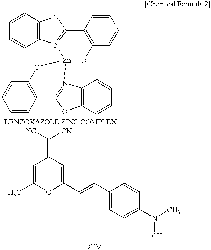
The number of layers and the reflectance of the dielectric mirror 12 can be varied, with the result that the spectral half-width of an emission wavelength (corresponding to color purity) and the degree of light amplification can be controlled. Furthermore, fine adjustment of an emission wavelength is possible by varying a resonance wavelength. In other words, by providing a resonator, each luminescent color can be made to have better monochromaticity than the luminescent color from the organic layer as shown in FIGS. 7a, 7 b and 7 c. As depicted in FIG. 7c, by changing the total number of layers of the dielectric mirror 12, the degree of monochromaticity can be varied. Therefore, the luminescent color can be selected to suit the purpose of use or the user. By this method, a full-color display can be adjusted finely. Note that the adjustment of a luminescent color can also be done on a mono-color display.
In the display according to the present embodiment, it is only necessary to provide organic EL panels 48R, 48G and 48B close to the dichroic prism 56, so that the display structure is very simple and can be made in a compact form. More specifically, a projector type display using a liquid crystal panel requires a complicated optical system to generate R, G and B rays. In contrast, the organic EL panel, being capable of emitting R, G and B rays by itself, does not require such a complicated optical system at all. Being free from the problem of attenuation as in light transmission through a liquid crystal or a polarizing plate, the organic EL panel can produce images with high luminance.
In the present embodiment, the organic EL panels 48R, 48G and 48B for R, G and B color are provided separately, but they can be incorporated in a single panel. More specifically, as shown in FIGS. 14A and 14B, by arranging the organic EL elements of primary colors successively and in a matrix formation and making the R, G and B pixels emit light according to video signals, a full-color display on a single organic EL panel can be achieved. In this case, the general structure of the device is the same as in the mono-color display shown in FIG. 5, in other words, a single organic EL panel 48 can effect a full-color display.
[Hologram System HUD]
FIG. 8 shows a structural example of a hologram system head up display (HUD) mounted on a vehicle. As illustrated, two mirrors 60 and 62 are arranged in front of an organic EL panel 48 to thereby control the direction of light output by emission of the organic EL panel 48. This light strikes a holographic lens 64, by which the light is reflected.
The reflected light is applied to a combiner 66 attached to the inner surface of the windshield glass. To the driver's eyes, a virtual image appears to be in front of the windshield glass, which corresponds to an image displayed on the organic EL panel 48. For example, preferably, a virtual image should be formed about 2 m ahead of the windshield glass.
With this kind of display device, rays of light for projection were conventionally obtained by passing light from a light source through a liquid crystal panel. In this conventional device structure, the light attenuation by the liquid crystal panel is great, so that it is necessary to provide a light source of large light quantity to obtain a high luminance. Therefore, the heat generated by the light source is large and heat dissipation has been a troublesome problem.
In the present embodiment, not much heat is generated because the organic EL panel 48 emits light by itself, and heat can be dissipated relatively easily because the organic EL panel 48 is flat in shape. Its structure is simpler than in a type of device that has a light source and a liquid crystal panel provided separately. Therefore, the general device structure can be made in a compact form. In an application as a full-color display, because of its very simple structure, it can be preferably mounted on a vehicle.
[Dichroic System HUD]
FIG. 9 shows a structural example of a dichroic system head up display (HUD) mounted on a vehicle. A mirror 70 is arranged in front of an organic EL display 48, and the light reflected from the mirror 70 passes through a collimating lens 72, and is applied to a dichroic filter 74 attached to the inner surface of the windshield. Therefore, a virtual image of an image of the organic EL panel 48 appears to be ahead of the windshield. A shutter 76 is provided to prevent a reverse convergence of sunlight by the collimating lens 72. Even in this structure, as in the hologram system HUD mentioned above, a compact-size device can be produced and cooling can be facilitated.
[Direct-Viewing Display]
In the above-mentioned structure, the projector type display has been described. However, since the organic EL panel 48 performs display by spontaneous luminescence, this panel can be used as a direct-viewing display.
The organic EL panel 48 according to the present embodiment has a resonator portion including the dielectric mirror 12 and the metal electrode 20. Therefore, light with high directivity is emitted in the direction of the front face of the organic EL panel 48. For this reason, it is possible to provide a display which features high visibility with high luminance for a viewer in front of the screen but has lower visibility for viewing from other directions.
By the organic EL panel 48 shown in FIG. 10, characters were displayed with a duty ratio of {fraction (1/32)} and a voltage of 10V. When measured in front of the display screen, the luminance was 500 cd/m2. A display of green color with better monochromaticity could be confirmed. From a position 45° sheering off from the front face, the luminance was 50 cd/m2, and a displayed image was indistinct. With an organic EL panel 48 without the dielectric mirror 12, the luminance at the front face was about 200 cd/m2, and a displayed image was visible also from a diagonal direction. The color purity was worse than in the present embodiment.
A high-directivity display such as this can be preferably used for an onboard display, an instrument panel display for example. In other words, as shown in FIG. 10, by installing a display so that it is distinct and highly visible only to a driver sitting correctly in the driver's seat, the driver can be made conscious of safe driving in a correct posture. A high-luminance image display is possible at 500 cd/m2 or higher. This bright display serves to make a farsighted elderly driver narrow his or her eyes unconsciously. Narrowing the eyes reduces chromatic aberration and helps the driver see a sharp image of display on the instrument panel nearby, that is to say, display becomes more easily visible. Also, because a sufficient luminance is obtainable, a secure display can be effected even when the sun shines through the window.
While there have been described what are at present considered to be preferred embodiments of the invention, it will be understood that various modifications may be made thereto, and it is intended that the appended claims cover all such modifications as fall within the true spirit and scope of the invention.
Claims (25)
1. A display device comprising:
a) a luminescent panel having a plurality of organic electroluminescent elements arranged in a matrix formation, wherein each of said plurality of organic electroluminescent elements includes:
a dielectric mirror,
a transparent electrode formed on said dielectric mirror,
a plurality of organic layers including a luminous layer, formed on said transparent electrode, and
a metal electrode formed on said plurality of organic layers; and
b) a driver for driving said electroluminescent elements on said luminescent panel.
2. A display device according to claim 1, wherein said transparent electrode and said metal electrode intersect, said luminescent panel having a pixel arranged at an intersection of said transparent electrode and said metal electrode in a matrix formation, and wherein display is performed by a matrix drive that controls a voltage between said transparent electrode and said metal electrode.
3. A display device according to claim 1, further comprising a projection lens through which light from said luminescent panel is projected onto a screen.
4. A display device according to claim 3, further comprising additional luminescent panels, each of the luminescent panels having different luminescent colors, light emission of said panels being individually controlled, and rays of light from said luminescent panels being combined and projected onto a screen.
5. A display device according to claim 4, wherein said luminescent panels respectively emit red, green and blue rays of light.
6. A display device according to claim 5, wherein the rays of light from said luminescent panels are combined by a dichroic prism.
7. A display device according to claim 1, wherein light including video information generated from said luminescent panel is used in a heads-up display system.
8. A display device according to claim 7, wherein said heads-up display system is a hologram system.
9. A display device according to claim 7, wherein said heads-up display system is a dichroic system.
10. A display device according to claim 1, wherein said luminescent panel provides a direct-viewing type display.
11. A display device according to claim 1, wherein said luminescent panel comprises said electroluminescent elements for respectively emitting R, G and B light, thereby being capable of a full-color display.
12. The display device according to claim 1, wherein the dielectric mirror comprises a SiO2 layer and a TiO2 layer.
13. A heads-up display (HUD) system comprising:
a) an organic electroluminescent (EL) display configured to emit an image, the organic EL display including:
1) a luminescent panel containing a plurality of organic electroluminescent elements, each of the organic electroluminescent elements including:
a glass substrate,
a dielectric mirror formed on the glass substrate,
a hole transport layer,
a transparent electrode disposed between the dielectric mirror and the hole transport layer,
a luminous layer formed on the hole transport layer, and
a metal electrode formed on the luminous layer; and
2) a driver configured to drive the plurality of organic electroluminescent elements on the luminescent panel; and
b) a mirror configured to reflect the image from the organic EL display onto a windshield.
14. A display device comprising:
a) a luminescent panel having a plurality of organic electroluminescent elements arranged in a matrix formation, wherein each of said plurality of organic electroluminescent elements includes:
a dielectric mirror,
a transparent electrode formed on said dielectric mirror,
a plurality of organic layers including a luminous layer, formed on said transparent electrode, and
a metal electrode formed on said plurality of organic layers;
wherein the dielectric mirror and the metal electrode constitute a micro-optical resonator that causes light of a given wavelength to resonate, and are spaced apart by about half the given wavelength to about one full given wavelength of the light that is resonated; and
b) a driver for driving said electroluminescent elements on said luminescent panel.
15. A display device according to claim 14, wherein said transparent electrode and said metal electrode intersect, said luminescent panel having a pixel arranged at an intersection of said transparent electrode and said metal electrode in a matrix formation, and wherein display is performed by a matrix drive that controls a voltage between said transparent electrode and said metal electrode.
16. A display device according to claim 14, further comprising a projection lens through which light from said luminescent panel is projected onto a screen.
17. A display device according to claim 16, further comprising additional luminescent panels, each of the luminescent panels having different luminescent colors, light emission of said panels being individually controlled, and rays of light from said luminescent panels being combined and projected onto a screen.
18. A display device according to claim 17, wherein said luminescent panels respectively emit red, green and blue rays of light.
19. A display device according to claim 18, wherein the rays of light from said luminescent panels are combined by a dichroic prism.
20. A display device according to claim 14, wherein light including video information generated from said luminescent panel is used in a heads-up display system.
21. A display device according to claim 20, wherein said heads-up display system is a hologram system.
22. A display device according to claim 20, wherein said heads-up display system is a dichroic system.
23. A display device according to claim 14, wherein said luminescent panel provides a direct-viewing type display.
24. A display device according to claim 14, wherein said luminescent panel comprises said electroluminescent elements for respectively emitting R, G and B light, thereby being capable of a full-color display.
25. The display device according to claim 14, wherein the dielectric mirror comprises a SiO2 layer and a TiO2 layer.
Applications Claiming Priority (2)
| Application Number | Priority Date | Filing Date | Title |
|---|---|---|---|
| JP9-230091 | 1997-08-26 | ||
| JP9230091A JPH1167448A (en) | 1997-08-26 | 1997-08-26 | Display device |
Publications (1)
| Publication Number | Publication Date |
|---|---|
| US6259423B1 true US6259423B1 (en) | 2001-07-10 |
Family
ID=16902415
Family Applications (1)
| Application Number | Title | Priority Date | Filing Date |
|---|---|---|---|
| US09/134,830 Expired - Fee Related US6259423B1 (en) | 1997-08-26 | 1998-08-17 | Display device using organic electroluminescent elements |
Country Status (2)
| Country | Link |
|---|---|
| US (1) | US6259423B1 (en) |
| JP (1) | JPH1167448A (en) |
Cited By (118)
| Publication number | Priority date | Publication date | Assignee | Title |
|---|---|---|---|---|
| US6429585B1 (en) * | 1999-02-12 | 2002-08-06 | Nec Corporation | Organic thin film EL panel and method of manufacturing the same |
| US20030099025A1 (en) * | 2001-09-07 | 2003-05-29 | Heinz-Bernhard Abel | Headup display |
| US20030214691A1 (en) * | 2002-05-08 | 2003-11-20 | Zeolux Corporation | Display devices using feedback enhanced light emitting diode |
| US20040017335A1 (en) * | 2002-05-10 | 2004-01-29 | Seiko Epson Corporation | Light emitting apparatus and electronic device |
| US20040021831A1 (en) * | 2002-07-31 | 2004-02-05 | Canon Kabushiki Kaisha, Tokyo, Japan | Projection type image display apparatus and image display system |
| US20040021833A1 (en) * | 2002-07-31 | 2004-02-05 | Canon Kabushiki Kaisha | Projection type image display apparatus and image display system |
| US20040061662A1 (en) * | 1999-10-18 | 2004-04-01 | Clarion Co., Ltd | Vehicle-mounted apparatus and method of controlling the same |
| US6741228B1 (en) * | 1998-07-24 | 2004-05-25 | Seiko Epson Corporation | Display apparatus |
| US20040134936A1 (en) * | 2003-01-13 | 2004-07-15 | Ritter Frank Georg | Cartridge closure with opening and closing means |
| US20040263070A1 (en) * | 2003-06-30 | 2004-12-30 | Lg Electronics Inc. | Organic electroluminescent display |
| US6890078B2 (en) | 2002-07-03 | 2005-05-10 | Canon Kabushiki Kaisha | Projection type image display apparatus and image display system |
| US6909229B2 (en) * | 2001-01-11 | 2005-06-21 | Tohoku Pioneer Corporation | Organic EL display |
| US6949879B1 (en) * | 1999-04-07 | 2005-09-27 | Microemissive Displays Limited | Optoelectronic display |
| US20050225233A1 (en) * | 2004-04-08 | 2005-10-13 | Eastman Kodak Company | OLED with color change media |
| US7034778B1 (en) * | 2000-04-05 | 2006-04-25 | Mannesmann Vdo Ag | Color head-up display, in particular for a vehicle |
| US20060181201A1 (en) * | 2005-02-17 | 2006-08-17 | Au Optronics Corp. | Organic electroluminescent device |
| US20070080631A1 (en) * | 2005-10-11 | 2007-04-12 | T. Chatani Co., Ltd. | Inorganic electroluminescence device driven by direct current |
| US20080164812A1 (en) * | 2007-01-08 | 2008-07-10 | Tpo Displays Corp. | Method for fabricating a system for displaying images |
| US20100328550A1 (en) * | 2007-11-24 | 2010-12-30 | Yong-Jing Wang | Projection system based on self emitting display panel |
| US8339033B2 (en) | 2009-06-11 | 2012-12-25 | Pioneer Corporation | Light emitting element and display device |
| RU2507639C2 (en) * | 2008-10-21 | 2014-02-20 | Конинклейке Филипс Электроникс Н.В. | Device of transparent organic light diode |
| EP2211386A3 (en) * | 2009-01-27 | 2014-08-27 | Oki Data Corporation | Light source apparatus and head-up display apparatus incorporating the light source apparatus |
| US8993951B2 (en) | 1996-03-25 | 2015-03-31 | Magna Electronics Inc. | Driver assistance system for a vehicle |
| US9014966B2 (en) | 2000-03-02 | 2015-04-21 | Magna Electronics Inc. | Driver assist system for vehicle |
| US9131120B2 (en) | 1996-05-22 | 2015-09-08 | Magna Electronics Inc. | Multi-camera vision system for a vehicle |
| US9171217B2 (en) | 2002-05-03 | 2015-10-27 | Magna Electronics Inc. | Vision system for vehicle |
| US9191634B2 (en) | 2004-04-15 | 2015-11-17 | Magna Electronics Inc. | Vision system for vehicle |
| US9244281B1 (en) | 2013-09-26 | 2016-01-26 | Rockwell Collins, Inc. | Display system and method using a detached combiner |
| US9244280B1 (en) | 2014-03-25 | 2016-01-26 | Rockwell Collins, Inc. | Near eye display system and method for display enhancement or redundancy |
| US9274339B1 (en) | 2010-02-04 | 2016-03-01 | Rockwell Collins, Inc. | Worn display system and method without requiring real time tracking for boresight precision |
| US9341846B2 (en) | 2012-04-25 | 2016-05-17 | Rockwell Collins Inc. | Holographic wide angle display |
| US9357208B2 (en) | 2011-04-25 | 2016-05-31 | Magna Electronics Inc. | Method and system for dynamically calibrating vehicular cameras |
| US9366864B1 (en) | 2011-09-30 | 2016-06-14 | Rockwell Collins, Inc. | System for and method of displaying information without need for a combiner alignment detector |
| US9436880B2 (en) | 1999-08-12 | 2016-09-06 | Magna Electronics Inc. | Vehicle vision system |
| US9440586B2 (en) | 2002-08-21 | 2016-09-13 | Magna Electronics Inc. | Multi-camera vision system for a vehicle |
| US9440535B2 (en) | 2006-08-11 | 2016-09-13 | Magna Electronics Inc. | Vision system for vehicle |
| US9491450B2 (en) | 2011-08-01 | 2016-11-08 | Magna Electronic Inc. | Vehicle camera alignment system |
| US9491451B2 (en) | 2011-11-15 | 2016-11-08 | Magna Electronics Inc. | Calibration system and method for vehicular surround vision system |
| US9507150B1 (en) | 2011-09-30 | 2016-11-29 | Rockwell Collins, Inc. | Head up display (HUD) using a bent waveguide assembly |
| US9508014B2 (en) | 2013-05-06 | 2016-11-29 | Magna Electronics Inc. | Vehicular multi-camera vision system |
| US9519089B1 (en) | 2014-01-30 | 2016-12-13 | Rockwell Collins, Inc. | High performance volume phase gratings |
| US9523852B1 (en) | 2012-03-28 | 2016-12-20 | Rockwell Collins, Inc. | Micro collimator system and method for a head up display (HUD) |
| US9563951B2 (en) | 2013-05-21 | 2017-02-07 | Magna Electronics Inc. | Vehicle vision system with targetless camera calibration |
| US9674413B1 (en) | 2013-04-17 | 2017-06-06 | Rockwell Collins, Inc. | Vision system and method having improved performance and solar mitigation |
| US9688200B2 (en) | 2013-03-04 | 2017-06-27 | Magna Electronics Inc. | Calibration system and method for multi-camera vision system |
| US9701246B2 (en) | 2013-05-21 | 2017-07-11 | Magna Electronics Inc. | Vehicle vision system using kinematic model of vehicle motion |
| US9715067B1 (en) | 2011-09-30 | 2017-07-25 | Rockwell Collins, Inc. | Ultra-compact HUD utilizing waveguide pupil expander with surface relief gratings in high refractive index materials |
| US9715110B1 (en) | 2014-09-25 | 2017-07-25 | Rockwell Collins, Inc. | Automotive head up display (HUD) |
| US9723272B2 (en) | 2012-10-05 | 2017-08-01 | Magna Electronics Inc. | Multi-camera image stitching calibration system |
| US20170237935A1 (en) * | 2016-02-15 | 2017-08-17 | Seiko Epson Corporation | Virtual image display apparatus and video device unit manufacturing method |
| US9762880B2 (en) | 2011-12-09 | 2017-09-12 | Magna Electronics Inc. | Vehicle vision system with customized display |
| US9834153B2 (en) | 2011-04-25 | 2017-12-05 | Magna Electronics Inc. | Method and system for dynamically calibrating vehicular cameras |
| US9900522B2 (en) | 2010-12-01 | 2018-02-20 | Magna Electronics Inc. | System and method of establishing a multi-camera image using pixel remapping |
| US9916660B2 (en) | 2015-01-16 | 2018-03-13 | Magna Electronics Inc. | Vehicle vision system with calibration algorithm |
| US9933684B2 (en) | 2012-11-16 | 2018-04-03 | Rockwell Collins, Inc. | Transparent waveguide display providing upper and lower fields of view having a specific light output aperture configuration |
| US9940528B2 (en) | 2004-12-23 | 2018-04-10 | Magna Electronics Inc. | Driver assistance system for vehicle |
| US9972100B2 (en) | 2007-08-17 | 2018-05-15 | Magna Electronics Inc. | Vehicular imaging system comprising an imaging device with a single image sensor and image processor for determining a totally blocked state or partially blocked state of the single image sensor as well as an automatic correction for misalignment of the imaging device |
| US10071687B2 (en) | 2011-11-28 | 2018-09-11 | Magna Electronics Inc. | Vision system for vehicle |
| US10088675B1 (en) | 2015-05-18 | 2018-10-02 | Rockwell Collins, Inc. | Turning light pipe for a pupil expansion system and method |
| US10108010B2 (en) | 2015-06-29 | 2018-10-23 | Rockwell Collins, Inc. | System for and method of integrating head up displays and head down displays |
| US10126552B2 (en) | 2015-05-18 | 2018-11-13 | Rockwell Collins, Inc. | Micro collimator system and method for a head up display (HUD) |
| US10144353B2 (en) | 2002-08-21 | 2018-12-04 | Magna Electronics Inc. | Multi-camera vision system for a vehicle |
| US10156681B2 (en) | 2015-02-12 | 2018-12-18 | Digilens Inc. | Waveguide grating device |
| US10179543B2 (en) | 2013-02-27 | 2019-01-15 | Magna Electronics Inc. | Multi-camera dynamic top view vision system |
| US10187590B2 (en) | 2015-10-27 | 2019-01-22 | Magna Electronics Inc. | Multi-camera vehicle vision system with image gap fill |
| US10241330B2 (en) | 2014-09-19 | 2019-03-26 | Digilens, Inc. | Method and apparatus for generating input images for holographic waveguide displays |
| US10247943B1 (en) | 2015-05-18 | 2019-04-02 | Rockwell Collins, Inc. | Head up display (HUD) using a light pipe |
| US10295824B2 (en) | 2017-01-26 | 2019-05-21 | Rockwell Collins, Inc. | Head up display with an angled light pipe |
| US10300859B2 (en) | 2016-06-10 | 2019-05-28 | Magna Electronics Inc. | Multi-sensor interior mirror device with image adjustment |
| US10359736B2 (en) | 2014-08-08 | 2019-07-23 | Digilens Inc. | Method for holographic mastering and replication |
| US10493916B2 (en) | 2012-02-22 | 2019-12-03 | Magna Electronics Inc. | Vehicle camera system with image manipulation |
| US10509241B1 (en) | 2009-09-30 | 2019-12-17 | Rockwell Collins, Inc. | Optical displays |
| US10545346B2 (en) | 2017-01-05 | 2020-01-28 | Digilens Inc. | Wearable heads up displays |
| US10598932B1 (en) | 2016-01-06 | 2020-03-24 | Rockwell Collins, Inc. | Head up display for integrating views of conformally mapped symbols and a fixed image source |
| US10642058B2 (en) | 2011-08-24 | 2020-05-05 | Digilens Inc. | Wearable data display |
| US10670876B2 (en) | 2011-08-24 | 2020-06-02 | Digilens Inc. | Waveguide laser illuminator incorporating a despeckler |
| US10678053B2 (en) | 2009-04-27 | 2020-06-09 | Digilens Inc. | Diffractive projection apparatus |
| US10690916B2 (en) | 2015-10-05 | 2020-06-23 | Digilens Inc. | Apparatus for providing waveguide displays with two-dimensional pupil expansion |
| US10725312B2 (en) | 2007-07-26 | 2020-07-28 | Digilens Inc. | Laser illumination device |
| US10732407B1 (en) | 2014-01-10 | 2020-08-04 | Rockwell Collins, Inc. | Near eye head up display system and method with fixed combiner |
| US10732569B2 (en) | 2018-01-08 | 2020-08-04 | Digilens Inc. | Systems and methods for high-throughput recording of holographic gratings in waveguide cells |
| US10747982B2 (en) | 2013-07-31 | 2020-08-18 | Digilens Inc. | Method and apparatus for contact image sensing |
| US10795160B1 (en) | 2014-09-25 | 2020-10-06 | Rockwell Collins, Inc. | Systems for and methods of using fold gratings for dual axis expansion |
| US10793067B2 (en) | 2011-07-26 | 2020-10-06 | Magna Electronics Inc. | Imaging system for vehicle |
| US10859768B2 (en) | 2016-03-24 | 2020-12-08 | Digilens Inc. | Method and apparatus for providing a polarization selective holographic waveguide device |
| US10890707B2 (en) | 2016-04-11 | 2021-01-12 | Digilens Inc. | Holographic waveguide apparatus for structured light projection |
| US10914950B2 (en) | 2018-01-08 | 2021-02-09 | Digilens Inc. | Waveguide architectures and related methods of manufacturing |
| US10942430B2 (en) | 2017-10-16 | 2021-03-09 | Digilens Inc. | Systems and methods for multiplying the image resolution of a pixelated display |
| US10946799B2 (en) | 2015-04-21 | 2021-03-16 | Magna Electronics Inc. | Vehicle vision system with overlay calibration |
| US10976563B2 (en) | 2018-03-27 | 2021-04-13 | Seiko Epson Corporation | Display device |
| US11029526B2 (en) | 2018-03-27 | 2021-06-08 | Seiko Epson Corporation | Optical unit and display device |
| US11069882B2 (en) | 2018-03-27 | 2021-07-20 | Seiko Epson Corporation | Optical unit and display device |
| US11228700B2 (en) | 2015-10-07 | 2022-01-18 | Magna Electronics Inc. | Vehicle vision system camera with adaptive field of view |
| US11256155B2 (en) | 2012-01-06 | 2022-02-22 | Digilens Inc. | Contact image sensor using switchable Bragg gratings |
| US11277558B2 (en) | 2016-02-01 | 2022-03-15 | Magna Electronics Inc. | Vehicle vision system with master-slave camera configuration |
| US11300795B1 (en) | 2009-09-30 | 2022-04-12 | Digilens Inc. | Systems for and methods of using fold gratings coordinated with output couplers for dual axis expansion |
| US11307432B2 (en) | 2014-08-08 | 2022-04-19 | Digilens Inc. | Waveguide laser illuminator incorporating a Despeckler |
| US11308869B2 (en) * | 2019-09-26 | 2022-04-19 | Seiko Epson Corporation | Image light generation module and image display device |
| US11314084B1 (en) | 2011-09-30 | 2022-04-26 | Rockwell Collins, Inc. | Waveguide combiner system and method with less susceptibility to glare |
| US11320571B2 (en) | 2012-11-16 | 2022-05-03 | Rockwell Collins, Inc. | Transparent waveguide display providing upper and lower fields of view with uniform light extraction |
| US11366316B2 (en) | 2015-05-18 | 2022-06-21 | Rockwell Collins, Inc. | Head up display (HUD) using a light pipe |
| US11378732B2 (en) | 2019-03-12 | 2022-07-05 | DigLens Inc. | Holographic waveguide backlight and related methods of manufacturing |
| US11402801B2 (en) | 2018-07-25 | 2022-08-02 | Digilens Inc. | Systems and methods for fabricating a multilayer optical structure |
| US11433809B2 (en) | 2016-02-02 | 2022-09-06 | Magna Electronics Inc. | Vehicle vision system with smart camera video output |
| US11442222B2 (en) | 2019-08-29 | 2022-09-13 | Digilens Inc. | Evacuated gratings and methods of manufacturing |
| US11487131B2 (en) | 2011-04-07 | 2022-11-01 | Digilens Inc. | Laser despeckler based on angular diversity |
| US11513350B2 (en) | 2016-12-02 | 2022-11-29 | Digilens Inc. | Waveguide device with uniform output illumination |
| US11543594B2 (en) | 2019-02-15 | 2023-01-03 | Digilens Inc. | Methods and apparatuses for providing a holographic waveguide display using integrated gratings |
| US11675205B2 (en) | 2019-02-28 | 2023-06-13 | Seiko Epson Corporation | Image display device and virtual image display apparatus |
| US11681143B2 (en) | 2019-07-29 | 2023-06-20 | Digilens Inc. | Methods and apparatus for multiplying the image resolution and field-of-view of a pixelated display |
| US11726332B2 (en) | 2009-04-27 | 2023-08-15 | Digilens Inc. | Diffractive projection apparatus |
| US11726329B2 (en) | 2015-01-12 | 2023-08-15 | Digilens Inc. | Environmentally isolated waveguide display |
| US11747568B2 (en) | 2019-06-07 | 2023-09-05 | Digilens Inc. | Waveguides incorporating transmissive and reflective gratings and related methods of manufacturing |
| US11877054B2 (en) | 2011-09-21 | 2024-01-16 | Magna Electronics Inc. | Vehicular vision system using image data transmission and power supply via a coaxial cable |
| US12092914B2 (en) | 2018-01-08 | 2024-09-17 | Digilens Inc. | Systems and methods for manufacturing waveguide cells |
| US12140764B2 (en) | 2019-02-15 | 2024-11-12 | Digilens Inc. | Wide angle waveguide display |
| US12158612B2 (en) | 2021-03-05 | 2024-12-03 | Digilens Inc. | Evacuated periodic structures and methods of manufacturing |
| US12210153B2 (en) | 2019-01-14 | 2025-01-28 | Digilens Inc. | Holographic waveguide display with light control layer |
Families Citing this family (10)
| Publication number | Priority date | Publication date | Assignee | Title |
|---|---|---|---|---|
| CN100340136C (en) | 1998-09-02 | 2007-09-26 | 精工爱普生株式会社 | Light source and display device |
| US7755577B2 (en) * | 2005-09-26 | 2010-07-13 | Kyocera Corporation | Electroluminescent device |
| JP2001066366A (en) * | 1999-08-30 | 2001-03-16 | Fuji Photo Film Co Ltd | Method and apparatus for reading image information |
| JP4508522B2 (en) * | 2002-07-31 | 2010-07-21 | キヤノン株式会社 | Projection display |
| JP4712293B2 (en) * | 2003-10-01 | 2011-06-29 | 株式会社半導体エネルギー研究所 | projector |
| JP4732991B2 (en) * | 2005-09-26 | 2011-07-27 | 京セラ株式会社 | EL device |
| JP4291837B2 (en) | 2006-08-30 | 2009-07-08 | 株式会社沖データ | Projection display apparatus and image forming apparatus |
| JP5404709B2 (en) * | 2011-08-02 | 2014-02-05 | 株式会社沖データ | Semiconductor device, LED device, LED head, and image forming apparatus |
| US20150170549A1 (en) * | 2013-11-30 | 2015-06-18 | Kabushikigaisha Goto Kogaku Kenkyusho | Fixed-star projection cylinder |
| JP6900961B2 (en) * | 2019-02-28 | 2021-07-14 | セイコーエプソン株式会社 | Image display device and virtual image display device |
Citations (12)
| Publication number | Priority date | Publication date | Assignee | Title |
|---|---|---|---|---|
| US4539507A (en) | 1983-03-25 | 1985-09-03 | Eastman Kodak Company | Organic electroluminescent devices having improved power conversion efficiencies |
| US4847609A (en) * | 1986-09-26 | 1989-07-11 | Matsushita Electric Industrial Co., Ltd. | Electroluminescence display panel configured for minimized power consumption |
| US4876594A (en) * | 1985-03-12 | 1989-10-24 | Julius Schiffman | Apparatus for promoting the vigilance of a motor vehicle operator |
| US4927234A (en) * | 1987-08-21 | 1990-05-22 | The Secretary Of State For Defence In Her Britannic Majesty's Government Of The United Kingdom Of Great Britain And Northern Ireland | Optical system for head-up displays |
| JPH06275381A (en) | 1993-03-18 | 1994-09-30 | Hitachi Ltd | Multicolor luminous element and substrate thereof |
| US5405710A (en) * | 1993-11-22 | 1995-04-11 | At&T Corp. | Article comprising microcavity light sources |
| US5478658A (en) * | 1994-05-20 | 1995-12-26 | At&T Corp. | Article comprising a microcavity light source |
| JPH08213174A (en) | 1992-09-22 | 1996-08-20 | Hitachi Ltd | Organic electroluminescent element and substrate therefor |
| JPH09180883A (en) | 1995-10-27 | 1997-07-11 | Toyota Central Res & Dev Lab Inc | Micro optical resonator type organic electroluminescence device |
| US5780174A (en) | 1995-10-27 | 1998-07-14 | Kabushiki Kaisha Toyota Chuo Kenkyusho | Micro-optical resonator type organic electroluminescent device |
| US5828181A (en) * | 1995-05-29 | 1998-10-27 | Pioneer Electronic Corporation | Driving circuit for an organic electroluminescent element used in a display |
| US6005651A (en) * | 1992-08-04 | 1999-12-21 | Matsushita Electric Industrial Co., Ltd. | Display panel and projection display system with use of display panel |
Family Cites Families (5)
| Publication number | Priority date | Publication date | Assignee | Title |
|---|---|---|---|---|
| JPS63200872U (en) * | 1987-06-17 | 1988-12-23 | ||
| JP3169974B2 (en) * | 1991-04-08 | 2001-05-28 | パイオニア株式会社 | Organic electroluminescent display device and driving method thereof |
| JPH07230880A (en) * | 1993-12-20 | 1995-08-29 | Ricoh Co Ltd | Organic el display device |
| JP3420399B2 (en) * | 1995-07-28 | 2003-06-23 | キヤノン株式会社 | Light emitting element |
| JPH09114398A (en) * | 1995-10-24 | 1997-05-02 | Idemitsu Kosan Co Ltd | Organic EL display |
-
1997
- 1997-08-26 JP JP9230091A patent/JPH1167448A/en active Pending
-
1998
- 1998-08-17 US US09/134,830 patent/US6259423B1/en not_active Expired - Fee Related
Patent Citations (14)
| Publication number | Priority date | Publication date | Assignee | Title |
|---|---|---|---|---|
| US4539507A (en) | 1983-03-25 | 1985-09-03 | Eastman Kodak Company | Organic electroluminescent devices having improved power conversion efficiencies |
| US4876594A (en) * | 1985-03-12 | 1989-10-24 | Julius Schiffman | Apparatus for promoting the vigilance of a motor vehicle operator |
| US4847609A (en) * | 1986-09-26 | 1989-07-11 | Matsushita Electric Industrial Co., Ltd. | Electroluminescence display panel configured for minimized power consumption |
| US4927234A (en) * | 1987-08-21 | 1990-05-22 | The Secretary Of State For Defence In Her Britannic Majesty's Government Of The United Kingdom Of Great Britain And Northern Ireland | Optical system for head-up displays |
| US6005651A (en) * | 1992-08-04 | 1999-12-21 | Matsushita Electric Industrial Co., Ltd. | Display panel and projection display system with use of display panel |
| JPH08213174A (en) | 1992-09-22 | 1996-08-20 | Hitachi Ltd | Organic electroluminescent element and substrate therefor |
| JPH06275381A (en) | 1993-03-18 | 1994-09-30 | Hitachi Ltd | Multicolor luminous element and substrate thereof |
| US5554911A (en) | 1993-03-18 | 1996-09-10 | Hitachi, Ltd. | Light-emitting elements |
| US5405710A (en) * | 1993-11-22 | 1995-04-11 | At&T Corp. | Article comprising microcavity light sources |
| US5478658A (en) * | 1994-05-20 | 1995-12-26 | At&T Corp. | Article comprising a microcavity light source |
| US5674636A (en) * | 1994-05-20 | 1997-10-07 | Dodabalapur; Ananth | Article comprising a microcavity light source |
| US5828181A (en) * | 1995-05-29 | 1998-10-27 | Pioneer Electronic Corporation | Driving circuit for an organic electroluminescent element used in a display |
| US5780174A (en) | 1995-10-27 | 1998-07-14 | Kabushiki Kaisha Toyota Chuo Kenkyusho | Micro-optical resonator type organic electroluminescent device |
| JPH09180883A (en) | 1995-10-27 | 1997-07-11 | Toyota Central Res & Dev Lab Inc | Micro optical resonator type organic electroluminescence device |
Cited By (269)
| Publication number | Priority date | Publication date | Assignee | Title |
|---|---|---|---|---|
| US8993951B2 (en) | 1996-03-25 | 2015-03-31 | Magna Electronics Inc. | Driver assistance system for a vehicle |
| US9131120B2 (en) | 1996-05-22 | 2015-09-08 | Magna Electronics Inc. | Multi-camera vision system for a vehicle |
| US6741228B1 (en) * | 1998-07-24 | 2004-05-25 | Seiko Epson Corporation | Display apparatus |
| US6429585B1 (en) * | 1999-02-12 | 2002-08-06 | Nec Corporation | Organic thin film EL panel and method of manufacturing the same |
| US6949879B1 (en) * | 1999-04-07 | 2005-09-27 | Microemissive Displays Limited | Optoelectronic display |
| US9436880B2 (en) | 1999-08-12 | 2016-09-06 | Magna Electronics Inc. | Vehicle vision system |
| US20040061662A1 (en) * | 1999-10-18 | 2004-04-01 | Clarion Co., Ltd | Vehicle-mounted apparatus and method of controlling the same |
| US7315291B2 (en) * | 1999-10-18 | 2008-01-01 | Clarion Co., Ltd. | Vehicle-mounted apparatus and method of controlling the same |
| US9809168B2 (en) | 2000-03-02 | 2017-11-07 | Magna Electronics Inc. | Driver assist system for vehicle |
| US9014966B2 (en) | 2000-03-02 | 2015-04-21 | Magna Electronics Inc. | Driver assist system for vehicle |
| US9315151B2 (en) | 2000-03-02 | 2016-04-19 | Magna Electronics Inc. | Driver assist system for vehicle |
| US10179545B2 (en) | 2000-03-02 | 2019-01-15 | Magna Electronics Inc. | Park-aid system for vehicle |
| US7034778B1 (en) * | 2000-04-05 | 2006-04-25 | Mannesmann Vdo Ag | Color head-up display, in particular for a vehicle |
| US6909229B2 (en) * | 2001-01-11 | 2005-06-21 | Tohoku Pioneer Corporation | Organic EL display |
| US20030099025A1 (en) * | 2001-09-07 | 2003-05-29 | Heinz-Bernhard Abel | Headup display |
| US6886971B2 (en) * | 2001-09-07 | 2005-05-03 | Siemens Aktiengesellschaft | Headup display |
| US9555803B2 (en) | 2002-05-03 | 2017-01-31 | Magna Electronics Inc. | Driver assistance system for vehicle |
| US10118618B2 (en) | 2002-05-03 | 2018-11-06 | Magna Electronics Inc. | Vehicular control system using cameras and radar sensor |
| US9171217B2 (en) | 2002-05-03 | 2015-10-27 | Magna Electronics Inc. | Vision system for vehicle |
| US10351135B2 (en) | 2002-05-03 | 2019-07-16 | Magna Electronics Inc. | Vehicular control system using cameras and radar sensor |
| US9834216B2 (en) | 2002-05-03 | 2017-12-05 | Magna Electronics Inc. | Vehicular control system using cameras and radar sensor |
| US9643605B2 (en) | 2002-05-03 | 2017-05-09 | Magna Electronics Inc. | Vision system for vehicle |
| US10683008B2 (en) | 2002-05-03 | 2020-06-16 | Magna Electronics Inc. | Vehicular driving assist system using forward-viewing camera |
| US11203340B2 (en) | 2002-05-03 | 2021-12-21 | Magna Electronics Inc. | Vehicular vision system using side-viewing camera |
| US9985249B2 (en) | 2002-05-08 | 2018-05-29 | Zeolux Corporation | Display devices using feedback enhanced light emitting diode |
| WO2003096757A1 (en) * | 2002-05-08 | 2003-11-20 | Zeolux Corporation | Feedback enhanced ligth emitting device |
| US20040069995A1 (en) * | 2002-05-08 | 2004-04-15 | Zeolux Corporation | Feedback enhanced light emitting device |
| US20040066824A1 (en) * | 2002-05-08 | 2004-04-08 | Zeolux Corporation | Lighting devices using feedback enhanced light emitting diode |
| US20030214691A1 (en) * | 2002-05-08 | 2003-11-20 | Zeolux Corporation | Display devices using feedback enhanced light emitting diode |
| EP1504634A4 (en) * | 2002-05-08 | 2007-07-18 | Zeolux Corp | LIGHTING DEVICES INVOLVING LIGHT EMITTING DIODES WITH IMPROVED RETROACTION |
| US9761839B2 (en) | 2002-05-08 | 2017-09-12 | Zeolux Corporation | Display devices using feedback enhanced light emitting diode |
| WO2003101156A1 (en) * | 2002-05-08 | 2003-12-04 | Zeolux Corporation | Display devices using feedback enhanced light emitting diode |
| US7335921B2 (en) | 2002-05-08 | 2008-02-26 | Zeolux Corporation | Lighting devices using feedback enhanced light emitting diode |
| US9129552B2 (en) | 2002-05-08 | 2015-09-08 | Zeolux Corporation | Display devices using feedback enhanced light emitting diode |
| EP1504634A1 (en) * | 2002-05-08 | 2005-02-09 | Zeolux Corporation | Lighting devices using feedback enhanced light emitting diode |
| US7710027B2 (en) | 2002-05-10 | 2010-05-04 | Seiko Epson Corporation | Light emitting apparatus including resin banks and electronic device having same |
| US20040017335A1 (en) * | 2002-05-10 | 2004-01-29 | Seiko Epson Corporation | Light emitting apparatus and electronic device |
| US20070236139A1 (en) * | 2002-05-10 | 2007-10-11 | Seiko Epson Corporation | Light emitting apparatus including resin banks and electronic device having same |
| US7242140B2 (en) * | 2002-05-10 | 2007-07-10 | Seiko Epson Corporation | Light emitting apparatus including resin banks and electronic device having same |
| US6890078B2 (en) | 2002-07-03 | 2005-05-10 | Canon Kabushiki Kaisha | Projection type image display apparatus and image display system |
| US6951393B2 (en) | 2002-07-31 | 2005-10-04 | Canon Kabushiki Kaisha | Projection type image display apparatus and image display system |
| US20050099116A1 (en) * | 2002-07-31 | 2005-05-12 | Canon Kabushiki Kaisha | Projection type image display apparatus and display device |
| US20040021831A1 (en) * | 2002-07-31 | 2004-02-05 | Canon Kabushiki Kaisha, Tokyo, Japan | Projection type image display apparatus and image display system |
| US20040021833A1 (en) * | 2002-07-31 | 2004-02-05 | Canon Kabushiki Kaisha | Projection type image display apparatus and image display system |
| US7090356B2 (en) | 2002-07-31 | 2006-08-15 | Canon Kabushiki Kaisha | Projection type image display apparatus and display device |
| US9440586B2 (en) | 2002-08-21 | 2016-09-13 | Magna Electronics Inc. | Multi-camera vision system for a vehicle |
| US10144353B2 (en) | 2002-08-21 | 2018-12-04 | Magna Electronics Inc. | Multi-camera vision system for a vehicle |
| US9796331B2 (en) | 2002-08-21 | 2017-10-24 | Magna Electronics Inc. | Multi-camera vision system for a vehicle |
| US20040134936A1 (en) * | 2003-01-13 | 2004-07-15 | Ritter Frank Georg | Cartridge closure with opening and closing means |
| US20040263070A1 (en) * | 2003-06-30 | 2004-12-30 | Lg Electronics Inc. | Organic electroluminescent display |
| US7211945B2 (en) * | 2003-06-30 | 2007-05-01 | Lg Electronics Inc. | Organic electroluminescent display device with improved image clarity and light emitting efficiency |
| US20050225233A1 (en) * | 2004-04-08 | 2005-10-13 | Eastman Kodak Company | OLED with color change media |
| US7057339B2 (en) * | 2004-04-08 | 2006-06-06 | Eastman Kodak Company | OLED with color change media |
| US10110860B1 (en) | 2004-04-15 | 2018-10-23 | Magna Electronics Inc. | Vehicular control system |
| US10306190B1 (en) | 2004-04-15 | 2019-05-28 | Magna Electronics Inc. | Vehicular control system |
| US10735695B2 (en) | 2004-04-15 | 2020-08-04 | Magna Electronics Inc. | Vehicular control system with traffic lane detection |
| US9428192B2 (en) | 2004-04-15 | 2016-08-30 | Magna Electronics Inc. | Vision system for vehicle |
| US10015452B1 (en) | 2004-04-15 | 2018-07-03 | Magna Electronics Inc. | Vehicular control system |
| US9736435B2 (en) | 2004-04-15 | 2017-08-15 | Magna Electronics Inc. | Vision system for vehicle |
| US10187615B1 (en) | 2004-04-15 | 2019-01-22 | Magna Electronics Inc. | Vehicular control system |
| US9948904B2 (en) | 2004-04-15 | 2018-04-17 | Magna Electronics Inc. | Vision system for vehicle |
| US9191634B2 (en) | 2004-04-15 | 2015-11-17 | Magna Electronics Inc. | Vision system for vehicle |
| US11503253B2 (en) | 2004-04-15 | 2022-11-15 | Magna Electronics Inc. | Vehicular control system with traffic lane detection |
| US11847836B2 (en) | 2004-04-15 | 2023-12-19 | Magna Electronics Inc. | Vehicular control system with road curvature determination |
| US9609289B2 (en) | 2004-04-15 | 2017-03-28 | Magna Electronics Inc. | Vision system for vehicle |
| US10462426B2 (en) | 2004-04-15 | 2019-10-29 | Magna Electronics Inc. | Vehicular control system |
| US10308180B2 (en) | 2004-09-14 | 2019-06-04 | Magna Electronics Inc. | Rear backup system for a vehicle |
| US11813987B2 (en) | 2004-09-14 | 2023-11-14 | Magna Electronics Inc. | Vehicular trailer hitching assist system |
| US11577646B2 (en) | 2004-09-14 | 2023-02-14 | Magna Electronics Inc. | Vehicular trailer hitching assist system |
| US11155210B2 (en) | 2004-09-14 | 2021-10-26 | Magna Electronics Inc. | Vehicular driving assist system including multiple cameras and radar sensor |
| US10556542B2 (en) | 2004-09-14 | 2020-02-11 | Magna Electronics Inc. | Rear backup system for a vehicle |
| US10800331B1 (en) | 2004-09-14 | 2020-10-13 | Magna Electronics Inc. | Vehicular vision system including rear backup camera |
| US10703274B2 (en) | 2004-09-14 | 2020-07-07 | Magna Electronics Inc. | Vehicular multi-camera vision system including rear backup camera |
| US11308720B2 (en) | 2004-12-23 | 2022-04-19 | Magna Electronics Inc. | Vehicular imaging system |
| US9940528B2 (en) | 2004-12-23 | 2018-04-10 | Magna Electronics Inc. | Driver assistance system for vehicle |
| US12118806B2 (en) | 2004-12-23 | 2024-10-15 | Magna Electronics Inc. | Vehicular imaging system |
| US10509972B2 (en) | 2004-12-23 | 2019-12-17 | Magna Electronics Inc. | Vehicular vision system |
| US20060181201A1 (en) * | 2005-02-17 | 2006-08-17 | Au Optronics Corp. | Organic electroluminescent device |
| US7417369B2 (en) * | 2005-02-17 | 2008-08-26 | Au Optronics Corp. | Organic electroluminescent device with light-transmissive optical compensation layer |
| US20070080631A1 (en) * | 2005-10-11 | 2007-04-12 | T. Chatani Co., Ltd. | Inorganic electroluminescence device driven by direct current |
| US8258690B2 (en) * | 2005-10-11 | 2012-09-04 | Kuraray Co., Ltd. | High brightness inorganic electroluminescence device driven by direct current |
| US11951900B2 (en) | 2006-08-11 | 2024-04-09 | Magna Electronics Inc. | Vehicular forward viewing image capture system |
| US10787116B2 (en) | 2006-08-11 | 2020-09-29 | Magna Electronics Inc. | Adaptive forward lighting system for vehicle comprising a control that adjusts the headlamp beam in response to processing of image data captured by a camera |
| US11148583B2 (en) | 2006-08-11 | 2021-10-19 | Magna Electronics Inc. | Vehicular forward viewing image capture system |
| US10071676B2 (en) | 2006-08-11 | 2018-09-11 | Magna Electronics Inc. | Vision system for vehicle |
| US11396257B2 (en) | 2006-08-11 | 2022-07-26 | Magna Electronics Inc. | Vehicular forward viewing image capture system |
| US11623559B2 (en) | 2006-08-11 | 2023-04-11 | Magna Electronics Inc. | Vehicular forward viewing image capture system |
| US9440535B2 (en) | 2006-08-11 | 2016-09-13 | Magna Electronics Inc. | Vision system for vehicle |
| US20080164812A1 (en) * | 2007-01-08 | 2008-07-10 | Tpo Displays Corp. | Method for fabricating a system for displaying images |
| US10725312B2 (en) | 2007-07-26 | 2020-07-28 | Digilens Inc. | Laser illumination device |
| US11328447B2 (en) | 2007-08-17 | 2022-05-10 | Magna Electronics Inc. | Method of blockage determination and misalignment correction for vehicular vision system |
| US9972100B2 (en) | 2007-08-17 | 2018-05-15 | Magna Electronics Inc. | Vehicular imaging system comprising an imaging device with a single image sensor and image processor for determining a totally blocked state or partially blocked state of the single image sensor as well as an automatic correction for misalignment of the imaging device |
| US11908166B2 (en) | 2007-08-17 | 2024-02-20 | Magna Electronics Inc. | Vehicular imaging system with misalignment correction of camera |
| US10726578B2 (en) | 2007-08-17 | 2020-07-28 | Magna Electronics Inc. | Vehicular imaging system with blockage determination and misalignment correction |
| US8845109B2 (en) * | 2007-11-24 | 2014-09-30 | Yong-Jing Wang | Projection system based on self emitting display panel |
| US20100328550A1 (en) * | 2007-11-24 | 2010-12-30 | Yong-Jing Wang | Projection system based on self emitting display panel |
| RU2507639C2 (en) * | 2008-10-21 | 2014-02-20 | Конинклейке Филипс Электроникс Н.В. | Device of transparent organic light diode |
| EP2211386A3 (en) * | 2009-01-27 | 2014-08-27 | Oki Data Corporation | Light source apparatus and head-up display apparatus incorporating the light source apparatus |
| US11726332B2 (en) | 2009-04-27 | 2023-08-15 | Digilens Inc. | Diffractive projection apparatus |
| US10678053B2 (en) | 2009-04-27 | 2020-06-09 | Digilens Inc. | Diffractive projection apparatus |
| US11175512B2 (en) | 2009-04-27 | 2021-11-16 | Digilens Inc. | Diffractive projection apparatus |
| US8541941B2 (en) | 2009-06-11 | 2013-09-24 | Pioneer Corporation | Light emitting element |
| US8339033B2 (en) | 2009-06-11 | 2012-12-25 | Pioneer Corporation | Light emitting element and display device |
| US11300795B1 (en) | 2009-09-30 | 2022-04-12 | Digilens Inc. | Systems for and methods of using fold gratings coordinated with output couplers for dual axis expansion |
| US10509241B1 (en) | 2009-09-30 | 2019-12-17 | Rockwell Collins, Inc. | Optical displays |
| US9274339B1 (en) | 2010-02-04 | 2016-03-01 | Rockwell Collins, Inc. | Worn display system and method without requiring real time tracking for boresight precision |
| US10868974B2 (en) | 2010-12-01 | 2020-12-15 | Magna Electronics Inc. | Method for determining alignment of vehicular cameras |
| US11553140B2 (en) | 2010-12-01 | 2023-01-10 | Magna Electronics Inc. | Vehicular vision system with multiple cameras |
| US9900522B2 (en) | 2010-12-01 | 2018-02-20 | Magna Electronics Inc. | System and method of establishing a multi-camera image using pixel remapping |
| US11487131B2 (en) | 2011-04-07 | 2022-11-01 | Digilens Inc. | Laser despeckler based on angular diversity |
| US10202077B2 (en) | 2011-04-25 | 2019-02-12 | Magna Electronics Inc. | Method for dynamically calibrating vehicular cameras |
| US9834153B2 (en) | 2011-04-25 | 2017-12-05 | Magna Electronics Inc. | Method and system for dynamically calibrating vehicular cameras |
| US10640041B2 (en) | 2011-04-25 | 2020-05-05 | Magna Electronics Inc. | Method for dynamically calibrating vehicular cameras |
| US10654423B2 (en) | 2011-04-25 | 2020-05-19 | Magna Electronics Inc. | Method and system for dynamically ascertaining alignment of vehicular cameras |
| US9357208B2 (en) | 2011-04-25 | 2016-05-31 | Magna Electronics Inc. | Method and system for dynamically calibrating vehicular cameras |
| US11554717B2 (en) | 2011-04-25 | 2023-01-17 | Magna Electronics Inc. | Vehicular vision system that dynamically calibrates a vehicular camera |
| US10919458B2 (en) | 2011-04-25 | 2021-02-16 | Magna Electronics Inc. | Method and system for calibrating vehicular cameras |
| US11007934B2 (en) | 2011-04-25 | 2021-05-18 | Magna Electronics Inc. | Method for dynamically calibrating a vehicular camera |
| US11285873B2 (en) | 2011-07-26 | 2022-03-29 | Magna Electronics Inc. | Method for generating surround view images derived from image data captured by cameras of a vehicular surround view vision system |
| US10793067B2 (en) | 2011-07-26 | 2020-10-06 | Magna Electronics Inc. | Imaging system for vehicle |
| US9491450B2 (en) | 2011-08-01 | 2016-11-08 | Magna Electronic Inc. | Vehicle camera alignment system |
| US10670876B2 (en) | 2011-08-24 | 2020-06-02 | Digilens Inc. | Waveguide laser illuminator incorporating a despeckler |
| US11287666B2 (en) | 2011-08-24 | 2022-03-29 | Digilens, Inc. | Wearable data display |
| US10642058B2 (en) | 2011-08-24 | 2020-05-05 | Digilens Inc. | Wearable data display |
| US12143712B2 (en) | 2011-09-21 | 2024-11-12 | Magna Electronics Inc. | Vehicular vision system using image data transmission and power supply via a coaxial cable |
| US11877054B2 (en) | 2011-09-21 | 2024-01-16 | Magna Electronics Inc. | Vehicular vision system using image data transmission and power supply via a coaxial cable |
| US11314084B1 (en) | 2011-09-30 | 2022-04-26 | Rockwell Collins, Inc. | Waveguide combiner system and method with less susceptibility to glare |
| US9715067B1 (en) | 2011-09-30 | 2017-07-25 | Rockwell Collins, Inc. | Ultra-compact HUD utilizing waveguide pupil expander with surface relief gratings in high refractive index materials |
| US10401620B1 (en) | 2011-09-30 | 2019-09-03 | Rockwell Collins, Inc. | Waveguide combiner system and method with less susceptibility to glare |
| US9977247B1 (en) | 2011-09-30 | 2018-05-22 | Rockwell Collins, Inc. | System for and method of displaying information without need for a combiner alignment detector |
| US9366864B1 (en) | 2011-09-30 | 2016-06-14 | Rockwell Collins, Inc. | System for and method of displaying information without need for a combiner alignment detector |
| US9599813B1 (en) | 2011-09-30 | 2017-03-21 | Rockwell Collins, Inc. | Waveguide combiner system and method with less susceptibility to glare |
| US9507150B1 (en) | 2011-09-30 | 2016-11-29 | Rockwell Collins, Inc. | Head up display (HUD) using a bent waveguide assembly |
| US10264249B2 (en) | 2011-11-15 | 2019-04-16 | Magna Electronics Inc. | Calibration system and method for vehicular surround vision system |
| US9491451B2 (en) | 2011-11-15 | 2016-11-08 | Magna Electronics Inc. | Calibration system and method for vehicular surround vision system |
| US11787338B2 (en) | 2011-11-28 | 2023-10-17 | Magna Electronics Inc. | Vehicular vision system |
| US11305691B2 (en) | 2011-11-28 | 2022-04-19 | Magna Electronics Inc. | Vehicular vision system |
| US10099614B2 (en) | 2011-11-28 | 2018-10-16 | Magna Electronics Inc. | Vision system for vehicle |
| US11142123B2 (en) | 2011-11-28 | 2021-10-12 | Magna Electronics Inc. | Multi-camera vehicular vision system |
| US11634073B2 (en) | 2011-11-28 | 2023-04-25 | Magna Electronics Inc. | Multi-camera vehicular vision system |
| US12100166B2 (en) | 2011-11-28 | 2024-09-24 | Magna Electronics Inc. | Vehicular vision system |
| US10640040B2 (en) | 2011-11-28 | 2020-05-05 | Magna Electronics Inc. | Vision system for vehicle |
| US10071687B2 (en) | 2011-11-28 | 2018-09-11 | Magna Electronics Inc. | Vision system for vehicle |
| US10542244B2 (en) | 2011-12-09 | 2020-01-21 | Magna Electronics Inc. | Vehicle vision system with customized display |
| US11689703B2 (en) | 2011-12-09 | 2023-06-27 | Magna Electronics Inc. | Vehicular vision system with customized display |
| US10129518B2 (en) | 2011-12-09 | 2018-11-13 | Magna Electronics Inc. | Vehicle vision system with customized display |
| US11082678B2 (en) | 2011-12-09 | 2021-08-03 | Magna Electronics Inc. | Vehicular vision system with customized display |
| US9762880B2 (en) | 2011-12-09 | 2017-09-12 | Magna Electronics Inc. | Vehicle vision system with customized display |
| US11256155B2 (en) | 2012-01-06 | 2022-02-22 | Digilens Inc. | Contact image sensor using switchable Bragg gratings |
| US11577645B2 (en) | 2012-02-22 | 2023-02-14 | Magna Electronics Inc. | Vehicular vision system with image manipulation |
| US10493916B2 (en) | 2012-02-22 | 2019-12-03 | Magna Electronics Inc. | Vehicle camera system with image manipulation |
| US10926702B2 (en) | 2012-02-22 | 2021-02-23 | Magna Electronics Inc. | Vehicle camera system with image manipulation |
| US9523852B1 (en) | 2012-03-28 | 2016-12-20 | Rockwell Collins, Inc. | Micro collimator system and method for a head up display (HUD) |
| US11460621B2 (en) | 2012-04-25 | 2022-10-04 | Rockwell Collins, Inc. | Holographic wide angle display |
| US9341846B2 (en) | 2012-04-25 | 2016-05-17 | Rockwell Collins Inc. | Holographic wide angle display |
| US10690915B2 (en) | 2012-04-25 | 2020-06-23 | Rockwell Collins, Inc. | Holographic wide angle display |
| US10904489B2 (en) | 2012-10-05 | 2021-01-26 | Magna Electronics Inc. | Multi-camera calibration method for a vehicle moving along a vehicle assembly line |
| US11265514B2 (en) | 2012-10-05 | 2022-03-01 | Magna Electronics Inc. | Multi-camera calibration method for a vehicle moving along a vehicle assembly line |
| US9723272B2 (en) | 2012-10-05 | 2017-08-01 | Magna Electronics Inc. | Multi-camera image stitching calibration system |
| US10284818B2 (en) | 2012-10-05 | 2019-05-07 | Magna Electronics Inc. | Multi-camera image stitching calibration system |
| US9933684B2 (en) | 2012-11-16 | 2018-04-03 | Rockwell Collins, Inc. | Transparent waveguide display providing upper and lower fields of view having a specific light output aperture configuration |
| US11448937B2 (en) | 2012-11-16 | 2022-09-20 | Digilens Inc. | Transparent waveguide display for tiling a display having plural optical powers using overlapping and offset FOV tiles |
| US11815781B2 (en) | 2012-11-16 | 2023-11-14 | Rockwell Collins, Inc. | Transparent waveguide display |
| US20180373115A1 (en) * | 2012-11-16 | 2018-12-27 | Digilens, Inc. | Transparent Waveguide Display |
| US11320571B2 (en) | 2012-11-16 | 2022-05-03 | Rockwell Collins, Inc. | Transparent waveguide display providing upper and lower fields of view with uniform light extraction |
| US10179543B2 (en) | 2013-02-27 | 2019-01-15 | Magna Electronics Inc. | Multi-camera dynamic top view vision system |
| US10780827B2 (en) | 2013-02-27 | 2020-09-22 | Magna Electronics Inc. | Method for stitching images captured by multiple vehicular cameras |
| US11572015B2 (en) | 2013-02-27 | 2023-02-07 | Magna Electronics Inc. | Multi-camera vehicular vision system with graphic overlay |
| US10486596B2 (en) | 2013-02-27 | 2019-11-26 | Magna Electronics Inc. | Multi-camera dynamic top view vision system |
| US11192500B2 (en) | 2013-02-27 | 2021-12-07 | Magna Electronics Inc. | Method for stitching image data captured by multiple vehicular cameras |
| US9688200B2 (en) | 2013-03-04 | 2017-06-27 | Magna Electronics Inc. | Calibration system and method for multi-camera vision system |
| US9674413B1 (en) | 2013-04-17 | 2017-06-06 | Rockwell Collins, Inc. | Vision system and method having improved performance and solar mitigation |
| US9679367B1 (en) | 2013-04-17 | 2017-06-13 | Rockwell Collins, Inc. | HUD system and method with dynamic light exclusion |
| US9769381B2 (en) | 2013-05-06 | 2017-09-19 | Magna Electronics Inc. | Vehicular multi-camera vision system |
| US10574885B2 (en) | 2013-05-06 | 2020-02-25 | Magna Electronics Inc. | Method for displaying video images for a vehicular vision system |
| US11050934B2 (en) | 2013-05-06 | 2021-06-29 | Magna Electronics Inc. | Method for displaying video images for a vehicular vision system |
| US10057489B2 (en) | 2013-05-06 | 2018-08-21 | Magna Electronics Inc. | Vehicular multi-camera vision system |
| US11616910B2 (en) | 2013-05-06 | 2023-03-28 | Magna Electronics Inc. | Vehicular vision system with video display |
| US9508014B2 (en) | 2013-05-06 | 2016-11-29 | Magna Electronics Inc. | Vehicular multi-camera vision system |
| US10266115B2 (en) | 2013-05-21 | 2019-04-23 | Magna Electronics Inc. | Vehicle vision system using kinematic model of vehicle motion |
| US9563951B2 (en) | 2013-05-21 | 2017-02-07 | Magna Electronics Inc. | Vehicle vision system with targetless camera calibration |
| US11919449B2 (en) | 2013-05-21 | 2024-03-05 | Magna Electronics Inc. | Targetless vehicular camera calibration system |
| US11109018B2 (en) | 2013-05-21 | 2021-08-31 | Magna Electronics Inc. | Targetless vehicular camera misalignment correction method |
| US10780826B2 (en) | 2013-05-21 | 2020-09-22 | Magna Electronics Inc. | Method for determining misalignment of a vehicular camera |
| US9979957B2 (en) | 2013-05-21 | 2018-05-22 | Magna Electronics Inc. | Vehicle vision system with targetless camera calibration |
| US10567748B2 (en) | 2013-05-21 | 2020-02-18 | Magna Electronics Inc. | Targetless vehicular camera calibration method |
| US11597319B2 (en) | 2013-05-21 | 2023-03-07 | Magna Electronics Inc. | Targetless vehicular camera calibration system |
| US9701246B2 (en) | 2013-05-21 | 2017-07-11 | Magna Electronics Inc. | Vehicle vision system using kinematic model of vehicle motion |
| US11794647B2 (en) | 2013-05-21 | 2023-10-24 | Magna Electronics Inc. | Vehicular vision system having a plurality of cameras |
| US11447070B2 (en) | 2013-05-21 | 2022-09-20 | Magna Electronics Inc. | Method for determining misalignment of a vehicular camera |
| US10747982B2 (en) | 2013-07-31 | 2020-08-18 | Digilens Inc. | Method and apparatus for contact image sensing |
| US9244281B1 (en) | 2013-09-26 | 2016-01-26 | Rockwell Collins, Inc. | Display system and method using a detached combiner |
| US10732407B1 (en) | 2014-01-10 | 2020-08-04 | Rockwell Collins, Inc. | Near eye head up display system and method with fixed combiner |
| US9519089B1 (en) | 2014-01-30 | 2016-12-13 | Rockwell Collins, Inc. | High performance volume phase gratings |
| US9766465B1 (en) | 2014-03-25 | 2017-09-19 | Rockwell Collins, Inc. | Near eye display system and method for display enhancement or redundancy |
| US9244280B1 (en) | 2014-03-25 | 2016-01-26 | Rockwell Collins, Inc. | Near eye display system and method for display enhancement or redundancy |
| US10359736B2 (en) | 2014-08-08 | 2019-07-23 | Digilens Inc. | Method for holographic mastering and replication |
| US11307432B2 (en) | 2014-08-08 | 2022-04-19 | Digilens Inc. | Waveguide laser illuminator incorporating a Despeckler |
| US11709373B2 (en) | 2014-08-08 | 2023-07-25 | Digilens Inc. | Waveguide laser illuminator incorporating a despeckler |
| US11726323B2 (en) | 2014-09-19 | 2023-08-15 | Digilens Inc. | Method and apparatus for generating input images for holographic waveguide displays |
| US10241330B2 (en) | 2014-09-19 | 2019-03-26 | Digilens, Inc. | Method and apparatus for generating input images for holographic waveguide displays |
| US9715110B1 (en) | 2014-09-25 | 2017-07-25 | Rockwell Collins, Inc. | Automotive head up display (HUD) |
| US11579455B2 (en) | 2014-09-25 | 2023-02-14 | Rockwell Collins, Inc. | Systems for and methods of using fold gratings for dual axis expansion using polarized light for wave plates on waveguide faces |
| US10795160B1 (en) | 2014-09-25 | 2020-10-06 | Rockwell Collins, Inc. | Systems for and methods of using fold gratings for dual axis expansion |
| US11740472B2 (en) | 2015-01-12 | 2023-08-29 | Digilens Inc. | Environmentally isolated waveguide display |
| US11726329B2 (en) | 2015-01-12 | 2023-08-15 | Digilens Inc. | Environmentally isolated waveguide display |
| US10235775B2 (en) | 2015-01-16 | 2019-03-19 | Magna Electronics Inc. | Vehicle vision system with calibration algorithm |
| US9916660B2 (en) | 2015-01-16 | 2018-03-13 | Magna Electronics Inc. | Vehicle vision system with calibration algorithm |
| US11703645B2 (en) | 2015-02-12 | 2023-07-18 | Digilens Inc. | Waveguide grating device |
| US10156681B2 (en) | 2015-02-12 | 2018-12-18 | Digilens Inc. | Waveguide grating device |
| US10527797B2 (en) | 2015-02-12 | 2020-01-07 | Digilens Inc. | Waveguide grating device |
| US11535154B2 (en) | 2015-04-21 | 2022-12-27 | Magna Electronics Inc. | Method for calibrating a vehicular vision system |
| US10946799B2 (en) | 2015-04-21 | 2021-03-16 | Magna Electronics Inc. | Vehicle vision system with overlay calibration |
| US10698203B1 (en) | 2015-05-18 | 2020-06-30 | Rockwell Collins, Inc. | Turning light pipe for a pupil expansion system and method |
| US11366316B2 (en) | 2015-05-18 | 2022-06-21 | Rockwell Collins, Inc. | Head up display (HUD) using a light pipe |
| US10126552B2 (en) | 2015-05-18 | 2018-11-13 | Rockwell Collins, Inc. | Micro collimator system and method for a head up display (HUD) |
| US10746989B2 (en) | 2015-05-18 | 2020-08-18 | Rockwell Collins, Inc. | Micro collimator system and method for a head up display (HUD) |
| US10088675B1 (en) | 2015-05-18 | 2018-10-02 | Rockwell Collins, Inc. | Turning light pipe for a pupil expansion system and method |
| US10247943B1 (en) | 2015-05-18 | 2019-04-02 | Rockwell Collins, Inc. | Head up display (HUD) using a light pipe |
| US10108010B2 (en) | 2015-06-29 | 2018-10-23 | Rockwell Collins, Inc. | System for and method of integrating head up displays and head down displays |
| US11281013B2 (en) | 2015-10-05 | 2022-03-22 | Digilens Inc. | Apparatus for providing waveguide displays with two-dimensional pupil expansion |
| US10690916B2 (en) | 2015-10-05 | 2020-06-23 | Digilens Inc. | Apparatus for providing waveguide displays with two-dimensional pupil expansion |
| US11754842B2 (en) | 2015-10-05 | 2023-09-12 | Digilens Inc. | Apparatus for providing waveguide displays with two-dimensional pupil expansion |
| US11228700B2 (en) | 2015-10-07 | 2022-01-18 | Magna Electronics Inc. | Vehicle vision system camera with adaptive field of view |
| US11588963B2 (en) | 2015-10-07 | 2023-02-21 | Magna Electronics Inc. | Vehicle vision system camera with adaptive field of view |
| US11831972B2 (en) | 2015-10-07 | 2023-11-28 | Magna Electronics Inc. | Vehicular vision system with adaptive field of view |
| US11910123B2 (en) | 2015-10-27 | 2024-02-20 | Magna Electronics Inc. | System for processing image data for display using backward projection |
| US10187590B2 (en) | 2015-10-27 | 2019-01-22 | Magna Electronics Inc. | Multi-camera vehicle vision system with image gap fill |
| US10598932B1 (en) | 2016-01-06 | 2020-03-24 | Rockwell Collins, Inc. | Head up display for integrating views of conformally mapped symbols and a fixed image source |
| US11215834B1 (en) | 2016-01-06 | 2022-01-04 | Rockwell Collins, Inc. | Head up display for integrating views of conformally mapped symbols and a fixed image source |
| US11277558B2 (en) | 2016-02-01 | 2022-03-15 | Magna Electronics Inc. | Vehicle vision system with master-slave camera configuration |
| US11433809B2 (en) | 2016-02-02 | 2022-09-06 | Magna Electronics Inc. | Vehicle vision system with smart camera video output |
| US11708025B2 (en) | 2016-02-02 | 2023-07-25 | Magna Electronics Inc. | Vehicle vision system with smart camera video output |
| US10986303B2 (en) | 2016-02-15 | 2021-04-20 | Seiko Epson Corporation | Virtual image display apparatus and video device unit manufacturing method |
| US11570394B2 (en) | 2016-02-15 | 2023-01-31 | Seiko Epson Corporation | Virtual image display apparatus and video device unit manufacturing method |
| US10271003B2 (en) * | 2016-02-15 | 2019-04-23 | Seiko Epson Corporation | Virtual image display apparatus and video device unit manufacturing method |
| US10674108B2 (en) | 2016-02-15 | 2020-06-02 | Seiko Epson Corporation | Virtual image display apparatus and video device unit manufacturing method |
| US20170237935A1 (en) * | 2016-02-15 | 2017-08-17 | Seiko Epson Corporation | Virtual image display apparatus and video device unit manufacturing method |
| US10859768B2 (en) | 2016-03-24 | 2020-12-08 | Digilens Inc. | Method and apparatus for providing a polarization selective holographic waveguide device |
| US11604314B2 (en) | 2016-03-24 | 2023-03-14 | Digilens Inc. | Method and apparatus for providing a polarization selective holographic waveguide device |
| US10890707B2 (en) | 2016-04-11 | 2021-01-12 | Digilens Inc. | Holographic waveguide apparatus for structured light projection |
| US10300859B2 (en) | 2016-06-10 | 2019-05-28 | Magna Electronics Inc. | Multi-sensor interior mirror device with image adjustment |
| US11513350B2 (en) | 2016-12-02 | 2022-11-29 | Digilens Inc. | Waveguide device with uniform output illumination |
| US11586046B2 (en) | 2017-01-05 | 2023-02-21 | Digilens Inc. | Wearable heads up displays |
| US11194162B2 (en) | 2017-01-05 | 2021-12-07 | Digilens Inc. | Wearable heads up displays |
| US10545346B2 (en) | 2017-01-05 | 2020-01-28 | Digilens Inc. | Wearable heads up displays |
| US10705337B2 (en) | 2017-01-26 | 2020-07-07 | Rockwell Collins, Inc. | Head up display with an angled light pipe |
| US10295824B2 (en) | 2017-01-26 | 2019-05-21 | Rockwell Collins, Inc. | Head up display with an angled light pipe |
| US10942430B2 (en) | 2017-10-16 | 2021-03-09 | Digilens Inc. | Systems and methods for multiplying the image resolution of a pixelated display |
| US10914950B2 (en) | 2018-01-08 | 2021-02-09 | Digilens Inc. | Waveguide architectures and related methods of manufacturing |
| US12092914B2 (en) | 2018-01-08 | 2024-09-17 | Digilens Inc. | Systems and methods for manufacturing waveguide cells |
| US10732569B2 (en) | 2018-01-08 | 2020-08-04 | Digilens Inc. | Systems and methods for high-throughput recording of holographic gratings in waveguide cells |
| US11029526B2 (en) | 2018-03-27 | 2021-06-08 | Seiko Epson Corporation | Optical unit and display device |
| US10976563B2 (en) | 2018-03-27 | 2021-04-13 | Seiko Epson Corporation | Display device |
| US11747637B2 (en) | 2018-03-27 | 2023-09-05 | Seiko Epson Corporation | Display device |
| US11069882B2 (en) | 2018-03-27 | 2021-07-20 | Seiko Epson Corporation | Optical unit and display device |
| US11402801B2 (en) | 2018-07-25 | 2022-08-02 | Digilens Inc. | Systems and methods for fabricating a multilayer optical structure |
| US12210153B2 (en) | 2019-01-14 | 2025-01-28 | Digilens Inc. | Holographic waveguide display with light control layer |
| US12140764B2 (en) | 2019-02-15 | 2024-11-12 | Digilens Inc. | Wide angle waveguide display |
| US11543594B2 (en) | 2019-02-15 | 2023-01-03 | Digilens Inc. | Methods and apparatuses for providing a holographic waveguide display using integrated gratings |
| US11675205B2 (en) | 2019-02-28 | 2023-06-13 | Seiko Epson Corporation | Image display device and virtual image display apparatus |
| US11378732B2 (en) | 2019-03-12 | 2022-07-05 | DigLens Inc. | Holographic waveguide backlight and related methods of manufacturing |
| US11747568B2 (en) | 2019-06-07 | 2023-09-05 | Digilens Inc. | Waveguides incorporating transmissive and reflective gratings and related methods of manufacturing |
| US11681143B2 (en) | 2019-07-29 | 2023-06-20 | Digilens Inc. | Methods and apparatus for multiplying the image resolution and field-of-view of a pixelated display |
| US11442222B2 (en) | 2019-08-29 | 2022-09-13 | Digilens Inc. | Evacuated gratings and methods of manufacturing |
| US11899238B2 (en) | 2019-08-29 | 2024-02-13 | Digilens Inc. | Evacuated gratings and methods of manufacturing |
| US11592614B2 (en) | 2019-08-29 | 2023-02-28 | Digilens Inc. | Evacuated gratings and methods of manufacturing |
| US11308869B2 (en) * | 2019-09-26 | 2022-04-19 | Seiko Epson Corporation | Image light generation module and image display device |
| US12158612B2 (en) | 2021-03-05 | 2024-12-03 | Digilens Inc. | Evacuated periodic structures and methods of manufacturing |
Also Published As
| Publication number | Publication date |
|---|---|
| JPH1167448A (en) | 1999-03-09 |
Similar Documents
| Publication | Publication Date | Title |
|---|---|---|
| US6259423B1 (en) | Display device using organic electroluminescent elements | |
| KR0159258B1 (en) | Active Matrix Reflective Projection System | |
| JP3319438B2 (en) | Light source device and display device | |
| TWI236568B (en) | Projector | |
| KR100585543B1 (en) | Light source for projection display | |
| CN101971637B (en) | Projection system based on self emitting display panel | |
| CN100390599C (en) | Light source and display device | |
| US5353133A (en) | A display having a standard or reversed schieren microprojector at each picture element | |
| JP3433647B2 (en) | Projector device | |
| KR101405026B1 (en) | High dynamic range projection system | |
| TW548483B (en) | Light source and the display device | |
| JP3591220B2 (en) | Projector device | |
| US5517278A (en) | Viewfinder for video cameras | |
| US20080117491A1 (en) | Illumination systems for visual displays | |
| US5806950A (en) | Compact high resolution light valve projector | |
| JPH1132278A (en) | Projecting device | |
| JP2002049326A (en) | Plane light source and display element using the same | |
| JP2010160343A (en) | Projector | |
| JP2000003611A (en) | Lighting system, view finder, video camera, manufacture of lighting system, projection-type display device, display panel, image display device, driving method for display panel, and driving circuit for display panel | |
| JP2006317935A (en) | Projector device | |
| JP7510552B2 (en) | Vehicle information display system and information display system | |
| JP3963107B2 (en) | Light source device and display device | |
| JP2003057746A (en) | Light source device and display device | |
| WO2007040540A1 (en) | Light emitting diode projection display systems | |
| JPH04118620A (en) | Head-up display device for automobile |
Legal Events
| Date | Code | Title | Description |
|---|---|---|---|
| AS | Assignment |
Owner name: KABUSHIKI KAISHA TOYOTA CHUO KENKYUSHO, JAPAN Free format text: ASSIGNMENT OF ASSIGNORS INTEREST;ASSIGNORS:TOKITO, SHIZUO;TAGA, YASUNORI;REEL/FRAME:011759/0227 Effective date: 19980730 |
|
| CC | Certificate of correction | ||
| LAPS | Lapse for failure to pay maintenance fees | ||
| STCH | Information on status: patent discontinuation |
Free format text: PATENT EXPIRED DUE TO NONPAYMENT OF MAINTENANCE FEES UNDER 37 CFR 1.362 |
|
| FP | Lapsed due to failure to pay maintenance fee |
Effective date: 20050710 |