US6246221B1 - PMOS low drop-out voltage regulator using non-inverting variable gain stage - Google Patents
PMOS low drop-out voltage regulator using non-inverting variable gain stage Download PDFInfo
- Publication number
- US6246221B1 US6246221B1 US09/665,816 US66581600A US6246221B1 US 6246221 B1 US6246221 B1 US 6246221B1 US 66581600 A US66581600 A US 66581600A US 6246221 B1 US6246221 B1 US 6246221B1
- Authority
- US
- United States
- Prior art keywords
- voltage regulator
- output
- input
- gain
- pmos
- Prior art date
- Legal status (The legal status is an assumption and is not a legal conclusion. Google has not performed a legal analysis and makes no representation as to the accuracy of the status listed.)
- Expired - Lifetime
Links
- 230000004044 response Effects 0.000 claims abstract description 49
- 239000003990 capacitor Substances 0.000 claims abstract description 41
- 230000007423 decrease Effects 0.000 claims abstract description 7
- 238000006073 displacement reaction Methods 0.000 claims 10
- 230000001105 regulatory effect Effects 0.000 claims 2
- 230000008878 coupling Effects 0.000 claims 1
- 238000010168 coupling process Methods 0.000 claims 1
- 238000005859 coupling reaction Methods 0.000 claims 1
- 238000009877 rendering Methods 0.000 claims 1
- 238000004088 simulation Methods 0.000 description 42
- 230000001052 transient effect Effects 0.000 description 26
- 238000000034 method Methods 0.000 description 16
- 230000008569 process Effects 0.000 description 6
- 230000008901 benefit Effects 0.000 description 4
- 230000000694 effects Effects 0.000 description 4
- 230000033228 biological regulation Effects 0.000 description 3
- 230000003139 buffering effect Effects 0.000 description 3
- 238000010586 diagram Methods 0.000 description 3
- 230000010363 phase shift Effects 0.000 description 3
- 239000000919 ceramic Substances 0.000 description 2
- 239000003985 ceramic capacitor Substances 0.000 description 2
- 230000001419 dependent effect Effects 0.000 description 2
- 238000012986 modification Methods 0.000 description 2
- 230000004048 modification Effects 0.000 description 2
- 230000004075 alteration Effects 0.000 description 1
- 235000015278 beef Nutrition 0.000 description 1
- 230000008859 change Effects 0.000 description 1
- 238000010276 construction Methods 0.000 description 1
- 238000013016 damping Methods 0.000 description 1
- 230000006866 deterioration Effects 0.000 description 1
- 230000036039 immunity Effects 0.000 description 1
- 230000009467 reduction Effects 0.000 description 1
- 238000000638 solvent extraction Methods 0.000 description 1
- 238000006467 substitution reaction Methods 0.000 description 1
- 229910052715 tantalum Inorganic materials 0.000 description 1
- GUVRBAGPIYLISA-UHFFFAOYSA-N tantalum atom Chemical compound [Ta] GUVRBAGPIYLISA-UHFFFAOYSA-N 0.000 description 1
Images


Classifications
-
- G—PHYSICS
- G05—CONTROLLING; REGULATING
- G05F—SYSTEMS FOR REGULATING ELECTRIC OR MAGNETIC VARIABLES
- G05F1/00—Automatic systems in which deviations of an electric quantity from one or more predetermined values are detected at the output of the system and fed back to a device within the system to restore the detected quantity to its predetermined value or values, i.e. retroactive systems
- G05F1/10—Regulating voltage or current
- G05F1/46—Regulating voltage or current wherein the variable actually regulated by the final control device is DC
- G05F1/56—Regulating voltage or current wherein the variable actually regulated by the final control device is DC using semiconductor devices in series with the load as final control devices
- G05F1/575—Regulating voltage or current wherein the variable actually regulated by the final control device is DC using semiconductor devices in series with the load as final control devices characterised by the feedback circuit
Definitions
- This invention relates generally to voltage regulators, and more particularly to an internally compensated low drop-out (LDO) voltage regulator using a non-inverting variable gain stage to improve stability and optimize power supply rejection ratio (PSRR).
- LDO low drop-out
- PSRR power supply rejection ratio
- Active compensating capacitive multiplier structures and techniques are well known in the art.
- the specific type of compensating circuit used is dependent upon the particular application.
- One application of improving phase margin for example takes advantage of the Miller Effect by adding a Miller compensation capacitance in parallel with an inverting gain stage, e.g., the output stage of a two stage amplifier circuit.
- Such a configuration results in the well-known and desirable phenomenon called pole splitting, which advantageously multiplies the effective capacitance of the physical capacitor employed in the circuit. See, e.g., for background on compensation of amplifier circuits using Miller-compensating capacitance, Paul R. Gray and Robert g. Meyer, Analysis and Design of Analog Integrated Circuits, Third Ed., John Wiley & sons, Inc. New York, 1993, Ch. 9, especially pp. 607-623.
- Miller compensation provides an impedance shunt across the series pass device associated with LDO voltage regulators, via the compensation capacitor and Cgs. This impedance is undesirable since it causes an early roll-off in PSRR.
- Some conventional two-stage PMOS low drop-out voltage regulators suffer from very poor load regulation at light, or no load, conditions. This is due to the gate of the PMOS series pass being driven from a source follower, Vdsat+Vgs, where Vt can vary from +0.2 to ⁇ 0.2V for a natural NMOS device and +0.5 to +0.9V for a standard device. Such variations will ultimately force the first stage amplifier output devices to enter their triode region (linear mode) when the regulator is lightly loaded, resulting in a significant reduction in loop gain and hence deterioration in regulator performance.
- the basic architecture for a PMOS voltage regulator includes an error amplifier to drive a power PMOS transistor, that supplies load current anywhere from zero up to hundreds of milli-amperes.
- a very large external filter capacitor (micro-farad range) is connected at the output node to improve transient response when load current changes quickly and dramatically.
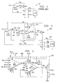
- FIG. 1 A block diagram of this basic architecture is shown in FIG. 1 .
- a PMOS voltage regulator Due to its special application, a PMOS voltage regulator has very unique load-dependent open loop frequency response characteristics. Under high supply voltage and minimum load current conditions, the power PMOS transistor operates in its sub-threshold region which produces a very large output impedance (hundreds of kilo-ohms range or more), wherein the output node will generate a low frequency pole. Under low supply voltage and maximum load current conditions, the PMOS transistor is well into its triode region in which the output impedance is extremely low (tens of ohms or less), wherein the pole at the output node is pushed out to the kilohertz range. The decades of movement associated with the pole presents significant design challenges, especially regarding stability compensation.
- g oAMP C c ⁇ ( G mMPO 2 ⁇ r oMPO ⁇ r oAMP ) CFILT .
- CFILT is generally much larger than C c (50,000 times larger if CFILT is 4.7 ⁇ F and C c is 90 pF. Even if the product of G 2 mMPO ⁇ r oMPO ⁇ r oAMP is large which basically equals the gain of a two-stage amplifier, f pd and f p2 are still not too far apart. Thus, the circuit will either suffer too poor phase margin or too low open-loop gain. Actually, it is possible that at low load current, the dominant pole is very likely at V out ; and at high load current, when G mMPO is significantly larger, the dominant pole is then at N_PG. Thus, an even worse scenario can occur somewhere along the load current in which the two poles are closest to each other resulting in a “pole swapping” point.
- the C c will degrade the PSRR performance.
- a simple way to look at this characteristic is: the C c in series with CFILT to ground directly loads the error amplifier, so when the ripple frequency on the supply line increases, the impedance from N_PG to ground decreases, which effectively “clamps” the gate voltage of MPO referenced to ground. The gate voltage will therefore not be able to track the ripples injected into the MPO source. This directly modulates the V gs of MPO and therefore also V out .
- the present invention is directed to a circuit architecture and technique for achieving good phase margin, highly desirable open-loop gain, and high power supply ripple rejection (PSRR) from an internally compensated PMOS low drop-out voltage regulator that is implemented to formulate a modified type of Miller compensation.
- This good phase margin and high open-loop gain is achieved by using a non-inverting variable gain stage that ensures the dominant pole is always at the same internal node regardless of load current (no “pole swapping” allowed).
- the present circuit further provides high PSRR by implementing the variable gain single stage amplifier such that a differential input has one input tied to C c while the other is at a dc voltage referenced to ground. Properly setting the input reference improves the PSRR.
- a conventional PMOS low drop-out voltage regulator is generally comprised of two gain stages in order to promote simplification of any related compensated closed loop system.
- the input stage of such a voltage regulator is formulated via a differential amplifier.
- the output stage comprises a series pass PMOS device.
- These two stages are generally coupled together via an impedance buffer, typically a source follower, to enable the input stage high impedance output to drive the large gate capacitance of the series pass PMOS device and thereby minimize the effect of an internal pole that would otherwise interfere with loop compensation.
- Miller capacitor multiplication, or “Pole-splitting”, is generally used by those skilled in the art to internally compensate the voltage regulator for use with ceramic output capacitors where the circuit designer cannot rely on an external compensating zero formed by the ESR associated with an electrolytic capacitor.
- the present invention provides a low drop-out (LDO) architecture that employs a variable gain stage to improve the internal compensation and achieve high PSRR performance from an internally compensated PMOS LDO voltage regulator.
- LDO low drop-out
- a preferred embodiment of the present invention comprises a differential amplifier input stage, a variable gain, non-inversion, single stage differential amplifier second stage, and an output stage comprising a series pass PMOS device.
- the second and output stages are coupled together via an impedance buffer (e.g., source follower, or unity-gain feedback amplifier) to enable the input stage high impedance output to drive the large gate capacitance of the series pass PMOS device and thereby minimize the effect of an internal pole that would otherwise interfere with loop compensation.
- the non-inversion variable gain differential amplifier stage has one input tied to C c and the other tied to a dc voltage referenced to ground.
- the Miller capacitance is then tied across multiple stages, i.e. the variable gain stage, the buffer, and the power PMOS.
- a feature of the present invention is associated with a higher frequency pole at the filter capacitor achieved through partitioning the LDO into a two stage amplifier and using miller capacitance for the compensation wherein the G m of the power PMOS is boosted at low load current and cut down at high load current using a wide band non-inversion variable gain stage.
- Another feature of the present invention is associated with better PSRR at high frequency by preventing the Miller capacitor from shunting the gate and drain of the pass PMOS device (in one embodiment, the left plate of the Miller capacitor is tied to one input of the variable gain stage while the other input is referenced to ground).
- Another feature of the present invention is associated with a unity-gain feedback configured Operational Transconductance Amplifier (OTA) gate drive circuit that substantially eliminates poor DC load regulation generally identified with conventional source follower drivers.
- OTA Operational Transconductance Amplifier
- Yet another feature of the present invention is associated with a flexible internally compensated PMOS low drop-out voltage regulator capable of functioning with a wide range of output capacitors.
- FIG. 1 illustrates a very well known low drop-out (LDO) voltage regulator using a PMOS pass device
- FIG. 2 illustrates a PMOS LDO according to one embodiment of the present invention
- FIG. 3 illustrates a PMOS LDO design according to one embodiment of the present invention using a traditional analog process
- FIG. 4 illustrates a more detailed view of the error amplifier stage and the non-inversion gain stage of the PMOS LDO shown in FIG. 3;
- FIG. 5 illustrates a more detailed view of the unity-gain buffer portion of the PMOS LDO shown in FIG. 3;
- FIG. 6 illustrates an AC response simulation of open loop gain with 50 m ohm ESR and 4.7 ⁇ F CFILT for the PMOS LDO shown in FIG. 3;
- FIG. 7 illustrates an AC response simulation of PSRR with 50 m ohm ESR and 4.7 ⁇ F CFILT for the PMOS LDO shown in FIG. 3;
- FIG. 8 illustrates an AC response simulation of open loop gain with 1 ohm ESR and 4.7 ⁇ F CFILT for the PMOS LDO shown in FIG. 3;
- FIG. 9 illustrates an AC response simulation of PSRR with 1 ohm ESR and 4.7 ⁇ F CFILT for the PMOS LDO shown in FIG. 3;
- FIG. 10 illustrates a transient response simulation of switching between no load and maximum load conditions with 50 m ohm ESR and 4.7 ⁇ F CFILT for the PMOS LDO shown in FIG. 3;
- FIG. 11 illustrates a transient response simulation when switching from no load to maximum load conditions with 50 m ohm ESR and 4.7 ⁇ F CFILT for the PMOS LDO shown in FIG. 3;
- FIG. 12 illustrates a transient response simulation when switching from maximum load to no load conditions with 50 m ohm ESR and 4.7 ⁇ F CFILT for the PMOS LDO shown in FIG. 3;
- FIG. 13 illustrates a transient response simulation of switching between no load and maximum load conditions with 2 ohm ESR and 4.7 ⁇ F CFILT for the PMOS LDO shown in FIG. 3;
- FIG. 14 illustrates a transient response simulation when switching from no load to maximum load conditions with 2 ohm ESR and 4.7 ⁇ F CFILT for the PMOS LDO shown in FIG. 3;
- FIG. 15 illustrates a transient response simulation when switching from maximum load to no load conditions with 2 ohm ESR and 4.7 ⁇ F CFILT for the PMOS LDO shown in FIG. 3;
- FIG. 16 FIG. 3 illustrates a PMOS LDO design in advanced digital process according to one embodiment of the present invention
- FIG. 17 illustrates a more detailed view of the error amplifier stage and the non-inversion gain stage of the PMOS LDO shown in FIG. 16;
- FIG. 18 illustrates a more detailed view of the rail-to-rail buffer portion of the PMOS LDO shown in FIG. 16;
- FIG. 19 illustrates an AC response simulation of open loop gain with 50 m ohm ESR and 1 ⁇ F CFILT for the PMOS LDO shown in FIG. 16;
- FIG. 20 illustrates an AC response simulation of PSRR with 50 m ohm ESR and 1 ⁇ F CFILT for the PMOS LDO shown in FIG. 16;
- FIG. 21 illustrates an AC response simulation of open loop gain with 2 ohm ESR and 1 ⁇ F CFILT for the PMOS LDO shown in FIG. 16;
- FIG. 22 illustrates an AC response simulation of PSRR with 2 ohm ESR and 1 ⁇ F CFILT for the PMOS LDO shown in FIG. 16;
- FIG. 23 illustrates a transient response simulation of switching between no load and maximum load conditions with 50 m ohm ESR and 1 ⁇ F CFILT for the PMOS LDO shown in FIG. 16;
- FIG. 24 illustrates a transient response simulation when switching from no load to maximum load conditions with 50 m ohm ESR and 1 ⁇ F CFILT for the PMOS LDO shown in FIG. 16;
- FIG. 25 illustrates a transient response simulation when switching from maximum load to no load conditions with 50 m ohm ESR and 1 ⁇ F CFILT for the PMOS LDO shown in FIG. 16;
- FIG. 26 illustrates a transient response simulation of switching between no load and maximum load conditions with 2 ohm ESR and 1 ⁇ F CFILT for the PMOS LDO shown in FIG. 16;
- FIG. 27 illustrates a transient response simulation when switching from no load to maximum load conditions with 2 ohm ESR and 1 ⁇ F CFILT for the PMOS LDO shown in FIG. 16;
- FIG. 28 illustrates a transient response simulation when switching from maximum load to no load conditions with 2 ohm ESR and 1 ⁇ F CFILT for the PMOS LDO shown in FIG. 16 .
- FIG. 1 illustrates a low drop-out (LDO) voltage regulator 100 using a PMOS pass device 102 and is well-known in the prior art; while FIG. 2 illustrates a PMOS LDO 200 according to one embodiment of the present invention.
- the PMOS LDO 200 importantly resolves the potential poor phase margins, low open-loop gains and less than desirable PSRR performance discussed herein above associated with the circuit architecture shown in FIG. 1 .
- the PMOS LDO 200 ensures that the dominant pole is always at the same internal node, regardless of load current, by preventing “pole swapping.” The foregoing analysis shows that one must boost G mMPO to split f pd and f p2 even further.
- f pd g oAMP 2 ⁇ ⁇ ⁇ ⁇ C c ⁇ ( 1 + A 2 ⁇ G mMPO ⁇ r oMPO ) ( 1 )
- a buffer 210 is needed for the (A 2 ) 202 stage to drive the power PMOS 206 .
- a source follower either a PMOS or NMOS device such as an isolated zero-Vt MOS will provide the requisite buffering characteristics so long as it preserves the necessary headroom for Vgs drive of the power PMOS 206 .
- a source follower will not provide the requisite buffering characteristics where no special devices are available and the supply voltage is getting ever lower however, such as when implementing a more advanced digital CMOS process.
- the buffer 210 can be seen to be implemented using both a unity-gain feedback single-stage amplifier 212 and a PMOS 214 in order to provide the requisite buffering characteristics.
- the unity-gain feedback single-stage amplifier 212 provides the same closed-loop bandwidth as a commonly used source follower and further allows the input/output to be designed rail-to-rail, thereby providing important advantages for low voltage applications. Since the buffer 210 input presents a high impedance input node 216 , circuit components need careful selection to push out the pole at the input node 216 .
- the non-inversion gain stage (A 2 ) 202 is a differential input, single stage amplifier having one input tied to C c 208 and the other input tied to a dc voltage V b 218 referenced to ground. This configuration was found to improve the PSRR since C c 208 in series with CFILT 220 present a low impedance to ground at high frequencies.
- the Miller capacitance C c 208 is tied across multiple stages, i.e. variable gain stage (A 2 ) 202 , buffer 210 and power PMOS 206 , more poles are present than that generated in a single stage Miller compensation implementation for an LDO similar to that illustrated in FIG. 1 .
- the loop formed by Miller capacitance C c 208 is itself a local unity-gain feedback at high frequencies; and therefore the LDO 200 must be implemented to ensure the loop formed by Miller capacitance C c 208 is stable over all requisite operating conditions.
- the worst case operating condition is at high current, when G mMPO is very large.
- the LDO 200 includes a variable gain stage (A 2 ) 202 , a simple solution is that, at high current, when G mMPO is large enough to push out the pole at CFILT 220 , the gain from variable gain stage (A 2 ) 202 can be cut down to prevent the bandwidth from getting too high.
- PMOS 214 serves this purpose by mirroring a portion of the load current into the buffer 210 in order to boost its driving capability at high load current conditions.
- the Miller capacitance C c 208 does not need to be very large to ensure a low enough dominant pole at N_AMP node 222 .
- the poles at (Vout) 224 , (N_A 2 ) 216 and (N_PG) 226 can all be pushed beyond the unity-gain bandwidth f bwLDO , so the ESR 228 of CFILT 220 can be very flexible. Due to limitations associated with stand-by current however, some time MPO 206 can have only 5-10 ⁇ A of bias current at no load. This results in an extremely low G mMPO and a lower second pole frequency. Then a reasonable ESR 228 is necessary to achieve a left hand plane (LHP) zero in order to save the phase shift. This zero however, is not required to be accurately placed as seen below with reference to the following figures.
- the gain of non-inversion gain stage (A 2 ) 202 must change in some controlled way. Specifically, when MPO 206 is turned on harder, the gain of (A 2 ) 202 should be lower. One way to accomplish this is to lower the output impedance of non-inversion gain stage (A 2 ) 202 according to MPO's 206 current.
- FIG. 3 is a top level diagram illustrating a PMOS LDO 300 according to one embodiment of the present invention and that was implemented using a traditional analog process and shows a power PMOS 302 , a non-inversion variable gain stage 304 and error amplifier stage 306 ; while FIG. 4 illustrates a more detailed view of the error amplifier stage 306 and the non-inversion variable gain stage 304 of the PMOS LDO 300 .
- the output 308 of the non-inversion variable gain stage 304 is shunted to the positive supply via a 300 k ohm resistor 400 in combination with a pair of diode connected PMOS transistors 402 , 404 .
- the gates of the PMOS transistor 402 , 404 can also be driven by the gate voltage of MPO 302 .
- FIG. 5 simply illustrates a more detailed view of the unity-gain buffer 500 used to drive the power MPO 302 of the PMOS LDO 300 shown in FIG. 3 .
- the gain provided by the non-inversion variable gain stage 202 must be cut down so that f p2 does not move out to a dramatically higher frequency so that the Miller compensation stage retains its single pole characteristic within its unity gain bandwidth. Since the node (N_A 2 ) 216 between the non-inversion variable gain stage 202 and the buffer stage 210 is a mid-frequency pole, f p2 can always be made lower than the pole at node (N_A 2 ) 216 by adjusting the gain of variable gain stage 202 over the full load current range.
- FIGS. 6-9 illustrate curve sets for high-Vdd-no-load, high-Vdd-high-load, and low-Vdd-high-load conditions respectively wherein FIG. 6 illustrates an AC response simulation of open loop gain with 50 m ohm ESR and 4.7 ⁇ F CFILT for the PMOS LDO 300 shown in FIG. 3;
- FIG. 7 illustrates an AC response simulation of PSRR with 50 m ohm ESR and 4.7 ⁇ F CFILT for the PMOS LDO 300 shown in FIG. 3;
- FIG. 8 illustrates an AC response simulation of open loop gain with 1 ohm ESR and 4.7 ⁇ F CFILT for the PMOS LDO 300 shown in FIG. 3;
- FIG. 9 illustrates an AC response simulation of PSRR with 1 ohm ESR and 4.7 ⁇ F CFILT for the PMOS LDO 300 shown in FIG. 3 .
- FIGS. 10-15 illustrate load regulation curve sets for high/low Vdd and resistive load/current source load, simulated with a simple 5nH+50 m ohm bonding wire model and a 1 nsec rise/fall time
- FIG. 10 illustrates a transient response simulation of no load and maximum load conditions with 50 m ohm ESR and 4.7 ⁇ F CFILT for the PMOS LDO 300 shown in FIG. 3
- FIG. 11 illustrates a transient response simulation when switching from no load to maximum load conditions with 50 m ohm ESR and 4.7 ⁇ F CFILT for the PMOS LDO 300 shown in FIG. 3
- FIG. 10 illustrates a transient response simulation of no load and maximum load conditions with 50 m ohm ESR and 4.7 ⁇ F CFILT for the PMOS LDO 300 shown in FIG. 3
- FIG. 11 illustrates a transient response simulation when switching from no load to maximum load conditions with 50 m ohm ESR and 4.7 ⁇ F CFILT for
- FIG. 12 illustrates a transient response simulation when switching from maximum load to no load conditions with 50 m ohm ESR and 4.7 ⁇ F CFILT for the PMOS LDO 300 shown in FIG. 3
- FIG. 13 illustrates a transient response simulation of no load and maximum load conditions with 2 ohm ESR and 4.7 ⁇ F CFILT for the PMOS LDO 300 shown in FIG. 3
- FIG. 14 illustrates a transient response simulation when switching from no load to maximum load conditions with 2 ohm ESR and 4.7 ⁇ F CFILT for the PMOS LDO 300 shown in FIG. 3
- FIG. 15 illustrates a transient response simulation when switching from maximum load to no load conditions with 2 ohm ESR and 4.7 ⁇ F CFILT for the PMOS LDO 300 shown in FIG. 3 .
- FIG. 16 is a top level schematic diagram illustrating a PMOS LDO 600 recently commercialized using 1533c035 advanced digital process techniques by Texas Instruments Incorporated of Dallas, Tex., according to one embodiment of the present invention.
- the LDO includes an error amplifier and non-inversion gain stage shown in element 606 as well as a rail-to-rail buffer shown in element 608 to drive the power PMOS 610 .
- a 10 k ohm resistor 602 in series with the Miller capacitor 604 can be seen to be shorted; though it could be used to add a LHP zero at 260 kHz to save the phase shift a little for no load current.
- the present inventor believes however, that it might lift up the gain curve for high load current and actually degrade the circuit stability such as discussed herein before.
- FIG. 17 illustrates a more detailed view of element 606 showing the error amplifier stage and the non-inversion gain stage of the PMOS LDO 600 shown in FIG. 16; while FIG. 18 illustrates a more detailed view of the rail-to-rail buffer 608 portion of the PMOS LDO 600 shown in FIG. 16 .
- FIGS. 19-22 illustrate curve sets for AC simulations done with 50 m ohm ESR and 1 ohm ESR respectively, wherein FIG. 19 illustrates an AC response simulation of open loop gain with 50 m ohm ESR and 1 ⁇ F CFILT for the PMOS LDO 600 shown in FIG. 16; FIG. 20 illustrates an AC response simulation of PSRR with 50 m ohm ESR and 1 ⁇ F CFILT for the PMOS LDO 600 shown in FIG. 16; FIG. 21 illustrates an AC response simulation of open loop gain with 2 ohm ESR and 1 ⁇ F CFILT for the PMOS LDO 600 shown in FIG. 16; and FIG. 22 illustrates an AC response simulation of PSRR with 2 ohm ESR and 1 ⁇ F CFILT for the PMOS LDO 600 shown in FIG. 16 .
- FIGS. 23-28 illustrate transient response curve sets for simulations associated with the PMOS LDO 600 , wherein FIG. 23 illustrates a transient response simulation of no load and maximum load conditions with 50 m ohm ESR and 1 ⁇ F CFILT for the PMOS LDO 600 shown in FIG. 16; FIG. 24 illustrates a transient response simulation when switching from no load to maximum load conditions with 50 m ohm ESR and 1 ⁇ F CFILT for the PMOS LDO 600 shown in FIG. 16; FIG. 25 illustrates a transient response simulation when switching from maximum load to no load conditions with 50 m ohm ESR and 1 ⁇ F CFILT for the PMOS LDO 600 shown in FIG. 16; FIG.
- FIG. 26 illustrates a transient response simulation of no load and maximum load conditions with 2 ohm ESR and 1 ⁇ F CFILT for the PMOS LDO 600 shown in FIG. 16
- FIG. 27 illustrates a transient response simulation when switching from no load to maximum load conditions with 2 ohm ESR and 1 ⁇ F CFILT for the PMOS LDO 600 shown in FIG. 16
- FIG. 28 illustrates a transient response simulation when switching from maximum load to no load conditions with 2 ohm ESR and 1 ⁇ F CFILT for the PMOS LDO 600 shown in FIG. 16 .
- a unity-gain feedback buffer (rail-to-rail to accommodate low supply digital processes), is employed to drive the power PMOS 206 so the pole at its gate is out of the band of interest.
- the present scheme cuts down the gain of non-inversion amplifier 202 when the load current is high where the Gm of the PMOS 206 is dramatically higher to ensure the second stage itself will have phase margin at f p2 .
- the Miller capacitor 208 is tied to a node 222 which is referenced to ground so that it won't degrade the PSRR.
Landscapes
- Engineering & Computer Science (AREA)
- Physics & Mathematics (AREA)
- Electromagnetism (AREA)
- General Physics & Mathematics (AREA)
- Radar, Positioning & Navigation (AREA)
- Automation & Control Theory (AREA)
- Amplifiers (AREA)
- Continuous-Control Power Sources That Use Transistors (AREA)
- Control Of Electrical Variables (AREA)
Abstract
A high power supply ripple rejection (PSRR) internally compensated low drop-out voltage regulator using an output PMOS pass device. The voltage regulator uses a non-inversion variable gain amplifier stage to adjust its gain in response to a load current passing through the output PMOS device such that as the load current decreases, the gain increases, wherein a second pole associated with the voltage regulator is pushed above a unity gain frequency associated with the voltage regulator. The non-inversion variable gain amplifier is further operational to adjust its gain in response to a load current passing through the power PMOS device such that as the load current increases, the gain decreases, wherein the voltage regulator unity gain bandwidth associated with the loop formed by the compensation capacitor is kept substantially constant.
Description
1. Field of the Invention
This invention relates generally to voltage regulators, and more particularly to an internally compensated low drop-out (LDO) voltage regulator using a non-inverting variable gain stage to improve stability and optimize power supply rejection ratio (PSRR).
2. Description of the Prior Art
Active compensating capacitive multiplier structures and techniques, e.g. nested Miller compensation, are well known in the art. The specific type of compensating circuit used is dependent upon the particular application. One application of improving phase margin for example, takes advantage of the Miller Effect by adding a Miller compensation capacitance in parallel with an inverting gain stage, e.g., the output stage of a two stage amplifier circuit. Such a configuration results in the well-known and desirable phenomenon called pole splitting, which advantageously multiplies the effective capacitance of the physical capacitor employed in the circuit. See, e.g., for background on compensation of amplifier circuits using Miller-compensating capacitance, Paul R. Gray and Robert g. Meyer, Analysis and Design of Analog Integrated Circuits, Third Ed., John Wiley & sons, Inc. New York, 1993, Ch. 9, especially pp. 607-623.
Recent trends associated with high efficiency battery powered equipment are creating increased demand for power management systems using DC/DC converters feeding low drop-out (LDO) voltage regulators. Applications requiring power from such LDO voltage regulators are becoming more sensitive to noise as application bandwidth requirements are pushed ever upward. This places far greater importance on the power supply ripple rejection (PSRR) characteristics associated with LDO voltage regulators since LDO voltage regulators are used to both clean up the output noise of the DC/DC converter and to provide power supply cross talk immunity from application blocks sharing the same raw DC supply.
There is also a trend showing an increased use of ceramic capacitors as output decoupling capacitors as contrasted with the once more typical use of tantalum capacitors in such applications. The significantly low equivalent series resistance (ESR) associated with ceramic capacitors however, makes reliance on ceramic output capacitor ESR characteristics no longer feasible to stabilize an LDO amplifier control loop. Thus, a need exists in the LDO amplifier art for an internal compensation technique allowing use of a wide range of output capacitor types. Such internal compensation techniques would allow the use of much smaller output capacitors and therefore provide a means for reducing both PCB real estate requirements and external component costs.
One widely popular accepted technique associated with internal compensation is known as “Pole splitting” or “Miller Compensation” such as discussed herein above. Miller compensation, however, provides an impedance shunt across the series pass device associated with LDO voltage regulators, via the compensation capacitor and Cgs. This impedance is undesirable since it causes an early roll-off in PSRR.
Some conventional two-stage PMOS low drop-out voltage regulators suffer from very poor load regulation at light, or no load, conditions. This is due to the gate of the PMOS series pass being driven from a source follower, Vdsat+Vgs, where Vt can vary from +0.2 to −0.2V for a natural NMOS device and +0.5 to +0.9V for a standard device. Such variations will ultimately force the first stage amplifier output devices to enter their triode region (linear mode) when the regulator is lightly loaded, resulting in a significant reduction in loop gain and hence deterioration in regulator performance.
The basic architecture for a PMOS voltage regulator includes an error amplifier to drive a power PMOS transistor, that supplies load current anywhere from zero up to hundreds of milli-amperes. Generally, a very large external filter capacitor (micro-farad range), is connected at the output node to improve transient response when load current changes quickly and dramatically. A block diagram of this basic architecture is shown in FIG. 1.
Due to its special application, a PMOS voltage regulator has very unique load-dependent open loop frequency response characteristics. Under high supply voltage and minimum load current conditions, the power PMOS transistor operates in its sub-threshold region which produces a very large output impedance (hundreds of kilo-ohms range or more), wherein the output node will generate a low frequency pole. Under low supply voltage and maximum load current conditions, the PMOS transistor is well into its triode region in which the output impedance is extremely low (tens of ohms or less), wherein the pole at the output node is pushed out to the kilohertz range. The decades of movement associated with the pole presents significant design challenges, especially regarding stability compensation.
Given the nature that the foregoing LDO is basically a two-stage amplifier, using a Miller capacitor for compensation is a very attractive approach. Tying a capacitor Cc from the output node Vout to the gate input N_PG of the PMOS transistor however, does not provide a desirable solution for two reasons: First, the two poles might not be separated far enough. For example, if the dominant pole is at N_PG due to the Miller effect, having a frequency at 
then the second pole comes in at a frequency of 
The distance between the two poles is: 
CFILT is generally much larger than Cc (50,000 times larger if CFILT is 4.7 μF and Cc is 90 pF. Even if the product of G2 mMPO·roMPO·roAMP is large which basically equals the gain of a two-stage amplifier, fpd and fp2 are still not too far apart. Thus, the circuit will either suffer too poor phase margin or too low open-loop gain. Actually, it is possible that at low load current, the dominant pole is very likely at Vout; and at high load current, when GmMPO is significantly larger, the dominant pole is then at N_PG. Thus, an even worse scenario can occur somewhere along the load current in which the two poles are closest to each other resulting in a “pole swapping” point.
Second, the Cc will degrade the PSRR performance. A simple way to look at this characteristic is: the Cc in series with CFILT to ground directly loads the error amplifier, so when the ripple frequency on the supply line increases, the impedance from N_PG to ground decreases, which effectively “clamps” the gate voltage of MPO referenced to ground. The gate voltage will therefore not be able to track the ripples injected into the MPO source. This directly modulates the Vgs of MPO and therefore also Vout.
In view of the foregoing, a need exists for an amplifier circuit architecture and technique capable of achieving better stability and higher PSRR performance from an internally compensated PMOS low drop-out voltage regulator than that presently achievable using conventional “Miller” or “Pole-splitting” techniques presently known in the art.
The present invention is directed to a circuit architecture and technique for achieving good phase margin, highly desirable open-loop gain, and high power supply ripple rejection (PSRR) from an internally compensated PMOS low drop-out voltage regulator that is implemented to formulate a modified type of Miller compensation. This good phase margin and high open-loop gain is achieved by using a non-inverting variable gain stage that ensures the dominant pole is always at the same internal node regardless of load current (no “pole swapping” allowed). The present circuit further provides high PSRR by implementing the variable gain single stage amplifier such that a differential input has one input tied to Cc while the other is at a dc voltage referenced to ground. Properly setting the input reference improves the PSRR.
A conventional PMOS low drop-out voltage regulator is generally comprised of two gain stages in order to promote simplification of any related compensated closed loop system. The input stage of such a voltage regulator is formulated via a differential amplifier. The output stage comprises a series pass PMOS device. These two stages are generally coupled together via an impedance buffer, typically a source follower, to enable the input stage high impedance output to drive the large gate capacitance of the series pass PMOS device and thereby minimize the effect of an internal pole that would otherwise interfere with loop compensation. Miller capacitor multiplication, or “Pole-splitting”, is generally used by those skilled in the art to internally compensate the voltage regulator for use with ceramic output capacitors where the circuit designer cannot rely on an external compensating zero formed by the ESR associated with an electrolytic capacitor. The impedance shunt formed through the Miller compensation capacitor and PMOS Cgs using this approach however, generates a PSRR that rolls off earlier than that associated with the open loop control performance of the regulator. Further, connecting the Miller capacitor across only the pass PMOS device usually results in pole swapping over the full load current range, as discussed herein before. In view of the foregoing, the present invention provides a low drop-out (LDO) architecture that employs a variable gain stage to improve the internal compensation and achieve high PSRR performance from an internally compensated PMOS LDO voltage regulator.
A preferred embodiment of the present invention comprises a differential amplifier input stage, a variable gain, non-inversion, single stage differential amplifier second stage, and an output stage comprising a series pass PMOS device. The second and output stages are coupled together via an impedance buffer (e.g., source follower, or unity-gain feedback amplifier) to enable the input stage high impedance output to drive the large gate capacitance of the series pass PMOS device and thereby minimize the effect of an internal pole that would otherwise interfere with loop compensation. The non-inversion variable gain differential amplifier stage has one input tied to Cc and the other tied to a dc voltage referenced to ground. The Miller capacitance is then tied across multiple stages, i.e. the variable gain stage, the buffer, and the power PMOS.
A feature of the present invention is associated with a higher frequency pole at the filter capacitor achieved through partitioning the LDO into a two stage amplifier and using miller capacitance for the compensation wherein the Gm of the power PMOS is boosted at low load current and cut down at high load current using a wide band non-inversion variable gain stage.
Another feature of the present invention is associated with better PSRR at high frequency by preventing the Miller capacitor from shunting the gate and drain of the pass PMOS device (in one embodiment, the left plate of the Miller capacitor is tied to one input of the variable gain stage while the other input is referenced to ground).
Another feature of the present invention is associated with a unity-gain feedback configured Operational Transconductance Amplifier (OTA) gate drive circuit that substantially eliminates poor DC load regulation generally identified with conventional source follower drivers.
Yet another feature of the present invention is associated with a flexible internally compensated PMOS low drop-out voltage regulator capable of functioning with a wide range of output capacitors.
Other aspects and features of the present invention and many of the attendant advantages of the present invention will be readily appreciated as the same become better understood by reference to the following detailed description when considered in connection with the accompanying drawings in which like reference numerals designate like parts throughout the figures thereof and wherein:
FIG. 1 illustrates a very well known low drop-out (LDO) voltage regulator using a PMOS pass device;
FIG. 2 illustrates a PMOS LDO according to one embodiment of the present invention;
FIG. 3 illustrates a PMOS LDO design according to one embodiment of the present invention using a traditional analog process;
FIG. 4 illustrates a more detailed view of the error amplifier stage and the non-inversion gain stage of the PMOS LDO shown in FIG. 3;
FIG. 5 illustrates a more detailed view of the unity-gain buffer portion of the PMOS LDO shown in FIG. 3;
FIG. 6 illustrates an AC response simulation of open loop gain with 50 m ohm ESR and 4.7 μF CFILT for the PMOS LDO shown in FIG. 3;
FIG. 7 illustrates an AC response simulation of PSRR with 50 m ohm ESR and 4.7 μF CFILT for the PMOS LDO shown in FIG. 3;
FIG. 8 illustrates an AC response simulation of open loop gain with 1 ohm ESR and 4.7 μF CFILT for the PMOS LDO shown in FIG. 3;
FIG. 9 illustrates an AC response simulation of PSRR with 1 ohm ESR and 4.7 μF CFILT for the PMOS LDO shown in FIG. 3;
FIG. 10 illustrates a transient response simulation of switching between no load and maximum load conditions with 50 m ohm ESR and 4.7 μF CFILT for the PMOS LDO shown in FIG. 3;
FIG. 11 illustrates a transient response simulation when switching from no load to maximum load conditions with 50 m ohm ESR and 4.7 μF CFILT for the PMOS LDO shown in FIG. 3;
FIG. 12 illustrates a transient response simulation when switching from maximum load to no load conditions with 50 m ohm ESR and 4.7 μF CFILT for the PMOS LDO shown in FIG. 3;
FIG. 13 illustrates a transient response simulation of switching between no load and maximum load conditions with 2 ohm ESR and 4.7 μF CFILT for the PMOS LDO shown in FIG. 3;
FIG. 14 illustrates a transient response simulation when switching from no load to maximum load conditions with 2 ohm ESR and 4.7 μF CFILT for the PMOS LDO shown in FIG. 3;
FIG. 15 illustrates a transient response simulation when switching from maximum load to no load conditions with 2 ohm ESR and 4.7 μF CFILT for the PMOS LDO shown in FIG. 3;
FIG. 16 FIG. 3 illustrates a PMOS LDO design in advanced digital process according to one embodiment of the present invention;
FIG. 17 illustrates a more detailed view of the error amplifier stage and the non-inversion gain stage of the PMOS LDO shown in FIG. 16;
FIG. 18 illustrates a more detailed view of the rail-to-rail buffer portion of the PMOS LDO shown in FIG. 16;
FIG. 19 illustrates an AC response simulation of open loop gain with 50 m ohm ESR and 1 μF CFILT for the PMOS LDO shown in FIG. 16;
FIG. 20 illustrates an AC response simulation of PSRR with 50 m ohm ESR and 1 μF CFILT for the PMOS LDO shown in FIG. 16;
FIG. 21 illustrates an AC response simulation of open loop gain with 2 ohm ESR and 1 μF CFILT for the PMOS LDO shown in FIG. 16;
FIG. 22 illustrates an AC response simulation of PSRR with 2 ohm ESR and 1 μF CFILT for the PMOS LDO shown in FIG. 16;
FIG. 23 illustrates a transient response simulation of switching between no load and maximum load conditions with 50 m ohm ESR and 1 μF CFILT for the PMOS LDO shown in FIG. 16;
FIG. 24 illustrates a transient response simulation when switching from no load to maximum load conditions with 50 m ohm ESR and 1 μF CFILT for the PMOS LDO shown in FIG. 16;
FIG. 25 illustrates a transient response simulation when switching from maximum load to no load conditions with 50 m ohm ESR and 1 μF CFILT for the PMOS LDO shown in FIG. 16;
FIG. 26 illustrates a transient response simulation of switching between no load and maximum load conditions with 2 ohm ESR and 1 μF CFILT for the PMOS LDO shown in FIG. 16;
FIG. 27 illustrates a transient response simulation when switching from no load to maximum load conditions with 2 ohm ESR and 1 μF CFILT for the PMOS LDO shown in FIG. 16; and
FIG. 28 illustrates a transient response simulation when switching from maximum load to no load conditions with 2 ohm ESR and 1 μF CFILT for the PMOS LDO shown in FIG. 16.
While the above-identified drawing figures set forth alternative embodiments, other embodiments of the present invention are also contemplated, as noted in the discussion. In all cases, this disclosure presents illustrated embodiments of the present invention by way of representation and not limitation. Numerous other modifications and embodiments can be devised by those skilled in the art which fall within the scope and spirit of the principles of this invention.
FIG. 1 illustrates a low drop-out (LDO) voltage regulator 100 using a PMOS pass device 102 and is well-known in the prior art; while FIG. 2 illustrates a PMOS LDO 200 according to one embodiment of the present invention. The PMOS LDO 200 importantly resolves the potential poor phase margins, low open-loop gains and less than desirable PSRR performance discussed herein above associated with the circuit architecture shown in FIG. 1. The PMOS LDO 200 ensures that the dominant pole is always at the same internal node, regardless of load current, by preventing “pole swapping.” The foregoing analysis shows that one must boost GmMPO to split fpd and fp2 even further. One straightforward way to accomplish this is to insert a non-inversion gain stage A2 (202) from the error amplifier 204 output to the PMOS 206 gate, and tie the Miller capacitor (Cc) 208, still at the error amplifier 204 output. This will cause the LDO's 200 dominant pole and second pole frequencies to be: 
and 
where fp2 is pushed further by a factor of A2, and the distance between the two poles (1) and (2) is 
Importantly, the −3 dB bandwidth of the non-inversion gain stage (A2) 202 should be much larger than the overall LDO 200 bandwidth, which is 
otherwise the (A2) 202 stage will introduce undesired phase shift. To achieve the requisite high −3 dB bandwidth, a buffer 210 is needed for the (A2) 202 stage to drive the power PMOS 206. Most commonly, a source follower, either a PMOS or NMOS device such as an isolated zero-Vt MOS will provide the requisite buffering characteristics so long as it preserves the necessary headroom for Vgs drive of the power PMOS 206. A source follower will not provide the requisite buffering characteristics where no special devices are available and the supply voltage is getting ever lower however, such as when implementing a more advanced digital CMOS process. The buffer 210 can be seen to be implemented using both a unity-gain feedback single-stage amplifier 212 and a PMOS 214 in order to provide the requisite buffering characteristics. The unity-gain feedback single-stage amplifier 212 provides the same closed-loop bandwidth as a commonly used source follower and further allows the input/output to be designed rail-to-rail, thereby providing important advantages for low voltage applications. Since the buffer 210 input presents a high impedance input node 216, circuit components need careful selection to push out the pole at the input node 216.
The non-inversion gain stage (A2) 202 is a differential input, single stage amplifier having one input tied to C c 208 and the other input tied to a dc voltage V b 218 referenced to ground. This configuration was found to improve the PSRR since C c 208 in series with CFILT 220 present a low impedance to ground at high frequencies.
Since the Miller capacitance C c 208 is tied across multiple stages, i.e. variable gain stage (A2) 202, buffer 210 and power PMOS 206, more poles are present than that generated in a single stage Miller compensation implementation for an LDO similar to that illustrated in FIG. 1. The loop formed by Miller capacitance C c 208 is itself a local unity-gain feedback at high frequencies; and therefore the LDO 200 must be implemented to ensure the loop formed by Miller capacitance C c 208 is stable over all requisite operating conditions. The worst case operating condition is at high current, when GmMPO is very large. Combined with A2, the unity gain bandwidth of this Miller stage will be 
which is actually the fp2 of the LDO 200. If this bandwidth is greater than other poles existing in this local loop, then this local loop is not stable any more, which will potentially cause the overall LDO 200 to become unstable. Under such undesirable conditions, a peak can appear at frequency fbwMILLER for the open loop gain of the overall LDO 200. Since the LDO 200 includes a variable gain stage (A2) 202, a simple solution is that, at high current, when GmMPO is large enough to push out the pole at CFILT 220, the gain from variable gain stage (A2) 202 can be cut down to prevent the bandwidth from getting too high. Since the pole at the PMOS 206 gate can also be a problem at high load current, a portion of the load current is fed into the buffer 210 to beef up the bias current such that the GmBUF is increased to push the pole at the PMOS 206 gate out further than fbwMILLER at high load current. Specifically, PMOS 214 serves this purpose by mirroring a portion of the load current into the buffer 210 in order to boost its driving capability at high load current conditions.
Because the LDO 200 has a variable gain stage (A2) 202, the Miller capacitance C c 208 does not need to be very large to ensure a low enough dominant pole at N_AMP node 222. The poles at (Vout) 224, (N_A2) 216 and (N_PG) 226 can all be pushed beyond the unity-gain bandwidth fbwLDO, so the ESR 228 of CFILT 220 can be very flexible. Due to limitations associated with stand-by current however, some time MPO 206 can have only 5-10 μA of bias current at no load. This results in an extremely low GmMPO and a lower second pole frequency. Then a reasonable ESR 228 is necessary to achieve a left hand plane (LHP) zero in order to save the phase shift. This zero however, is not required to be accurately placed as seen below with reference to the following figures.
In view of the foregoing, the gain of non-inversion gain stage (A2) 202 must change in some controlled way. Specifically, when MPO 206 is turned on harder, the gain of (A2) 202 should be lower. One way to accomplish this is to lower the output impedance of non-inversion gain stage (A2) 202 according to MPO's 206 current.
FIG. 3 is a top level diagram illustrating a PMOS LDO 300 according to one embodiment of the present invention and that was implemented using a traditional analog process and shows a power PMOS 302, a non-inversion variable gain stage 304 and error amplifier stage 306; while FIG. 4 illustrates a more detailed view of the error amplifier stage 306 and the non-inversion variable gain stage 304 of the PMOS LDO 300. The output 308 of the non-inversion variable gain stage 304 is shunted to the positive supply via a 300 k ohm resistor 400 in combination with a pair of diode connected PMOS transistors 402, 404. The gates of the PMOS transistor 402, 404 can also be driven by the gate voltage of MPO 302. Thus, when Vgs of MPO 302 gets larger (indicates larger load current), the shunt PMOS transistors 402, 404 will be on harder so the combined output impedance of non-inversion variable gain stage 304 will be lower (limited by the series 300 k ohm resistor 400. FIG. 5 simply illustrates a more detailed view of the unity-gain buffer 500 used to drive the power MPO 302 of the PMOS LDO 300 shown in FIG. 3.
In summary explanation of the above, at the low current end, where the Gm of the power PMOS (MPO) 206 is minimum, a minimum gain provided by the non-inversion variable gain stage 202 is necessary to drive the second pole ( 
unity gain bandwidth of the Miller compensation stage) far enough around or above LDO's 200 unity gain bandwidth. At the high load current end, where Gm of MPO 206 is maximum, the gain provided by the non-inversion variable gain stage 202 must be cut down so that fp2 does not move out to a dramatically higher frequency so that the Miller compensation stage retains its single pole characteristic within its unity gain bandwidth. Since the node (N_A2) 216 between the non-inversion variable gain stage 202 and the buffer stage 210 is a mid-frequency pole, fp2 can always be made lower than the pole at node (N_A2) 216 by adjusting the gain of variable gain stage 202 over the full load current range. Cutting down the output impedance of variable gain stage 202, as discussed above, provides multiple benefits. It both lowers the gain of variable gain stage 202 and drives the pole at node (N_A2) 216 further. The idea is to reduce the gain of gain stage 202 in order to compensate for the increased Gm of MPO 206.
FIGS. 6-9 illustrate curve sets for high-Vdd-no-load, high-Vdd-high-load, and low-Vdd-high-load conditions respectively wherein FIG. 6 illustrates an AC response simulation of open loop gain with 50 m ohm ESR and 4.7 μF CFILT for the PMOS LDO 300 shown in FIG. 3; FIG. 7 illustrates an AC response simulation of PSRR with 50 m ohm ESR and 4.7 μF CFILT for the PMOS LDO 300 shown in FIG. 3; FIG. 8 illustrates an AC response simulation of open loop gain with 1 ohm ESR and 4.7 μF CFILT for the PMOS LDO 300 shown in FIG. 3; and FIG. 9 illustrates an AC response simulation of PSRR with 1 ohm ESR and 4.7 μF CFILT for the PMOS LDO 300 shown in FIG. 3.
FIGS. 10-15 illustrate load regulation curve sets for high/low Vdd and resistive load/current source load, simulated with a simple 5nH+50 m ohm bonding wire model and a 1 nsec rise/fall time wherein FIG. 10 illustrates a transient response simulation of no load and maximum load conditions with 50 m ohm ESR and 4.7 μF CFILT for the PMOS LDO 300 shown in FIG. 3; FIG. 11 illustrates a transient response simulation when switching from no load to maximum load conditions with 50 m ohm ESR and 4.7 μF CFILT for the PMOS LDO 300 shown in FIG. 3; FIG. 12 illustrates a transient response simulation when switching from maximum load to no load conditions with 50 m ohm ESR and 4.7 μF CFILT for the PMOS LDO 300 shown in FIG. 3; FIG. 13 illustrates a transient response simulation of no load and maximum load conditions with 2 ohm ESR and 4.7 μF CFILT for the PMOS LDO 300 shown in FIG. 3; FIG. 14 illustrates a transient response simulation when switching from no load to maximum load conditions with 2 ohm ESR and 4.7 μF CFILT for the PMOS LDO 300 shown in FIG. 3; and FIG. 15 illustrates a transient response simulation when switching from maximum load to no load conditions with 2 ohm ESR and 4.7 μF CFILT for the PMOS LDO 300 shown in FIG. 3.
FIG. 16 is a top level schematic diagram illustrating a PMOS LDO 600 recently commercialized using 1533c035 advanced digital process techniques by Texas Instruments Incorporated of Dallas, Tex., according to one embodiment of the present invention. The LDO includes an error amplifier and non-inversion gain stage shown in element 606 as well as a rail-to-rail buffer shown in element 608 to drive the power PMOS 610. The LDO 600 ratings are: Vin from 2V to 3.6V, Vout=1.8V, Cc=60 pF, CFILT=1 μF, stand-by current=40 μA and max load current=50 mA. A 10 k ohm resistor 602 in series with the Miller capacitor 604 can be seen to be shorted; though it could be used to add a LHP zero at 260 kHz to save the phase shift a little for no load current. The present inventor believes however, that it might lift up the gain curve for high load current and actually degrade the circuit stability such as discussed herein before.
FIG. 17 illustrates a more detailed view of element 606 showing the error amplifier stage and the non-inversion gain stage of the PMOS LDO 600 shown in FIG. 16; while FIG. 18 illustrates a more detailed view of the rail-to-rail buffer 608 portion of the PMOS LDO 600 shown in FIG. 16.
FIGS. 19-22 illustrate curve sets for AC simulations done with 50 m ohm ESR and 1 ohm ESR respectively, wherein FIG. 19 illustrates an AC response simulation of open loop gain with 50 m ohm ESR and 1 μF CFILT for the PMOS LDO 600 shown in FIG. 16; FIG. 20 illustrates an AC response simulation of PSRR with 50 m ohm ESR and 1 μF CFILT for the PMOS LDO 600 shown in FIG. 16; FIG. 21 illustrates an AC response simulation of open loop gain with 2 ohm ESR and 1 μF CFILT for the PMOS LDO 600 shown in FIG. 16; and FIG. 22 illustrates an AC response simulation of PSRR with 2 ohm ESR and 1 μF CFILT for the PMOS LDO 600 shown in FIG. 16.
FIGS. 23-28 illustrate transient response curve sets for simulations associated with the PMOS LDO 600, wherein FIG. 23 illustrates a transient response simulation of no load and maximum load conditions with 50 m ohm ESR and 1 μF CFILT for the PMOS LDO 600 shown in FIG. 16; FIG. 24 illustrates a transient response simulation when switching from no load to maximum load conditions with 50 m ohm ESR and 1 μF CFILT for the PMOS LDO 600 shown in FIG. 16; FIG. 25 illustrates a transient response simulation when switching from maximum load to no load conditions with 50 m ohm ESR and 1 μF CFILT for the PMOS LDO 600 shown in FIG. 16; FIG. 26 illustrates a transient response simulation of no load and maximum load conditions with 2 ohm ESR and 1 μF CFILT for the PMOS LDO 600 shown in FIG. 16; FIG. 27 illustrates a transient response simulation when switching from no load to maximum load conditions with 2 ohm ESR and 1 μF CFILT for the PMOS LDO 600 shown in FIG. 16; and FIG. 28 illustrates a transient response simulation when switching from maximum load to no load conditions with 2 ohm ESR and 1 μF CFILT for the PMOS LDO 600 shown in FIG. 16.
The present invention therefore, implements a modified Miller compensation scheme using a non-inversion variable gain amplifier 202 in a manner that boosts the Gm of the power PMOS 206 at low load current to push out the second pole, which is 
beyond unity-gain bandwidth. A unity-gain feedback buffer (rail-to-rail to accommodate low supply digital processes), is employed to drive the power PMOS 206 so the pole at its gate is out of the band of interest. The present scheme cuts down the gain of non-inversion amplifier 202 when the load current is high where the Gm of the PMOS 206 is dramatically higher to ensure the second stage itself will have phase margin at fp2. Finally, the Miller capacitor 208 is tied to a node 222 which is referenced to ground so that it won't degrade the PSRR. In view of the foregoing, it can be seen the present invention presents a significant advancement in the art of internally compensated low drop-out voltage regulators using an output PMOS pass device.
This invention has been described in considerable detail in order to provide those skilled in the damping circuit art with the information needed to apply the novel principles and to construct and use such specialized components as are required. In view of the foregoing descriptions, it should be apparent that the present invention represents a significant departure from the prior art in construction and operation. However, while particular embodiments of the present invention have been described herein in detail, it is to be understood that various alterations, modifications and substitutions can be made therein without departing in any way from the spirit and scope of the present invention, as defined in the claims which follow. For example, while the embodiments set forth herein illustrate particular types of transistors, the present invention could just as well be implemented using a variety of transistor types including, but not limited to, e.g. CMOS, BiCMOS, Bipolar and HBT, among others. Further, while particular embodiments of the present invention have been described herein with reference to structures and methods of current and voltage control, the present invention shall be understood to also parallel structures and methods of current and voltage control as defined in the claims.
Claims (25)
1. A modified Miller-compensated voltage regulator having a unity gain frequency, the voltage regulator comprising:
an input error amplifier stage comprising a differential amplifier having an output, a first input and a second input;
a non-inversion variable gain amplifier stage having an output, a first input in communication with the differential amplifier output, and a second input connected to a dc voltage referenced to ground;
a unity gain buffer amplifier stage having an output, a first input in communication with the non-inversion amplifier stage output and a second input coupled to the output of the unity gain buffer amplifier stage;
a power PMOS having a gate in communication with the unity gain buffer amplifier stage output, a source coupled to a supply voltage and a drain that is configured to provide a regulated output voltage; and
a compensating capacitor coupled at one end to the drain of the power PMOS and coupled at its other end to the output of the input error amplifier stage to provide a compensation loop having internal poles and a unity gain frequency associated therewith.
2. The modified Miller compensated voltage regulator according to claim 1 further comprising a filter capacitor coupled at one end to the drain of the power PMOS and coupled at its opposite end to ground.
3. The modified Miller compensated voltage regulator according to claim 1 further comprising a voltage divider coupled to the drain of the power PMOS and configured to provide a feedback voltage to the second input of the differential amplifier.
4. The modified Miller compensated voltage regulator according to claim 3 wherein the first input of the differential amplifier is coupled to a predetermined reference voltage.
5. The modified Miller compensated voltage regulator according to claim 1 wherein the non-inversion variable gain amplifier is operational to adjust its gain in response to a load current such that as the load current increases, the gain decreases, wherein the unity gain bandwidth associated with the loop formed by the compensating (Miller) capacitor is kept substantially constant.
6. The modified Miller compensated voltage regulator according to claim 1 wherein the non-inversion variable gain amplifier is operational to push the internal poles in the compensation loop itself formed by the compensating capacitor to frequencies above the unity gain frequency associated with the compensation loop.
7. The modified Miller compensated voltage regulator according to claim 1 wherein the non-inversion variable gain amplifier is operational to adjust its gain in response to a load current such that as the load current decreases, the gain increases, wherein a second pole associated with the voltage regulator is pushed away from the unity gain frequency associated with the voltage regulator.
8. A modified Miller compensated voltage regulator comprising:
a differential amplifier input stage having a first input, a second input, and an output;
a non-inversion variable gain amplifier stage having an output, a first input connected to a reference voltage, and a second input coupled to the output of the differential amplifier input stage;
a PMOS output transistor having a source, drain and gate;
a unity gain buffer coupling the non-inversion variable gain amplifier stage to the gate of the PMOS output transistor; and
a feedback capacitor coupled at a first end to the PMOS output transistor drain, and coupled at a second end to the non-inversion variable gain amplifier stage second input to form a compensation loop; wherein the non-inversion variable gain amplifier stage, the unity gain buffer, the PMOS output transistor, and the feedback capacitor are responsive to a changing load current to control a unity gain bandwidth associated with the compensation loop.
9. The modified Miller compensated voltage regulator according to claim 8 wherein the feedback capacitor is referenced at both ends to a common ground associated with the voltage regulator.
10. The modified Miller compensated voltage regulator according to claim 8 further comprising a filter capacitor (CFILT) coupled at one end to the drain of the power PMOS and coupled at its opposite end to ground.
11. The modified Miller compensated voltage regulator according to claim 10 wherein the unity gain bandwidth associated with the compensation loop is defined by the equation 
where A2 is a gain associated with the non-inversion variable gain amplifier and GmMPO is a transconductance associated with the power PMOS.
12. A modified Miller compensated voltage regulator comprising:
an input amplifier stage configured to receive an input reference voltage and further configured to receive a feedback current via a nested Miller compensation capacitor associated with the voltage regulator to generate a displacement current to provide an effective Miller multiplied compensating capacitance;
a non-inversion variable gain amplifier stage having an output pole associated therewith, the non-inversion variable gain amplifier stage configured to receive the feedback displacement current associated with the nested Miller compensation capacitor such that the pole associated with the output of the non-inversion variable gain amplifier stage is pushed out to a frequency above a Unity Gain Frequency associated with the compensation loop and further configured to generate an amplified displacement current signal therefrom; and
an output amplifier stage having a pole associated therewith, the output amplifier stage configured to receive the amplified displacement current signal such that the pole associated with the output amplifier stage is pushed out to a frequency above the Unity Gain Frequency of the compensation loop thereby rendering the voltage regulator output stage capable of generating a stable regulated output voltage at frequencies in the vicinity of the control loop bandwidth associated with the voltage regulator.
13. A modified Miller compensated voltage regulator comprising:
means for generating a feedback current;
means for generating a displacement current from the feedback current;
means for amplifying the displacement current such that non-dominant poles associated with the voltage regulator are pushed to frequencies outside the control loop bandwidth of the voltage regulator; and
means for generating output voltage signals having substantially maximized power supply ripple rejection characteristics inside the control loop bandwidth.
14. The modified Miller compensated voltage regulator according to claim 13 wherein the means for generating a feedback current comprises a power PMOS device.
15. The modified Miller compensated voltage regulator according to claim 14 wherein the means for generating output voltage signals having substantially maximized power supply ripple rejection characteristics inside the control loop bandwidth comprises a unity gain buffer configured to receive the displacement current and drive the power PMOS device therefrom.
16. The modified Miller compensated voltage regulator according to claim 14 wherein the means for generating output voltage signals having substantially maximized power supply ripple rejection characteristics inside the control loop bandwidth comprises a source follower configured to receive the displacement current and drive the power PMOS device therefrom.
17. The modified Miller compensated voltage regulator according to claim 14 wherein the means for generating a feedback current further comprises a nested Miller compensation capacitor.
18. The modified Miller compensated voltage regulator according to claim 17 wherein the nested Miller compensation capacitor is configured such that each capacitor node is referenced to a common ground associated with the voltage regulator.
19. The modified Miller compensated voltage regulator according to claim 13 wherein the means for generating a displacement current comprises a voltage divider.
20. The modified Miller compensated voltage regulator according to claim 13 wherein the means for amplifying the displacement current such that non-dominant poles associated with the voltage regulator are pushed to frequencies outside the control loop bandwidth of the voltage regulator comprises a non-inversion variable gain amplifier.
21. A modified Miller compensated voltage regulator comprising:
a supply voltage node;
an output voltage node;
a ground;
an output power PMOS device having a source connected to the supply voltage node, a drain connected to the output voltage node, and a gate;
a common source PMOS device having a source connected to the supply voltage node, a gate connected to the gate of the power PMOS device, and a drain;
a unity gain buffer having a bias input connected to the drain of the common source PMOS device, an output connected to the gate of the power PMOS device, an inverting input connected to the buffer output, and a non-inverting input;
a non-inversion variable gain amplifier having an output connected to the unity gain buffer non-inverting input, a reference voltage input connected to a ground reference voltage, and a non-inverting input;
a differential amplifier having a bias input connected to the supply voltage node, an output connected to the non-inverting input of the non-inversion variable gain amplifier, an inverting input connected to a reference voltage, and a non-inverting input;
a voltage divider network having a first node connected to the power PMOS drain, a second node connected to ground, and a third node connected to the differential amplifier non-inverting input to provide a feedback voltage; and
a compensation capacitor connected at one end to the power PMOS device drain and connected at an opposite end to differential amplifier output.
22. The modified Miller compensated voltage regulator according to claim 21 further comprising a filter capacitor coupled at one end to the drain of the power PMOS device and connected at its opposite end to ground.
23. The modified Miller compensated voltage regulator according to claim 22 wherein the non-inversion variable gain amplifier, unity gain buffer, the power PMOS device, common source PMOS device, voltage divider network, filter capacitor, and compensation capacitor are responsive to a changing load current to control a unity gain bandwidth associated with the compensation loop.
24. The modified Miller compensated voltage regulator according to claim 21 wherein the non-inversion variable gain amplifier is operational to adjust its gain in response to a load current passing through the power PMOS device such that as the load current decreases, the gain increases, wherein a second pole associated with the voltage regulator is pushed above a unity gain frequency associated with the voltage regulator.
25. The modified Miller compensated voltage regulator according to claim 21 wherein the non-inversion variable gain amplifier is operational to adjust its gain in response to a load current passing through the power PMOS device such that as the load current increases, the gain decreases, wherein the voltage regulator unity gain bandwidth associated with a loop formed by the compensation capacitor is dept substantially constant.
Priority Applications (3)
| Application Number | Priority Date | Filing Date | Title |
|---|---|---|---|
| US09/665,816 US6246221B1 (en) | 2000-09-20 | 2000-09-20 | PMOS low drop-out voltage regulator using non-inverting variable gain stage |
| EP01000476A EP1191416A3 (en) | 2000-09-20 | 2001-09-20 | Voltage regulator |
| JP2001286768A JP4824881B2 (en) | 2000-09-20 | 2001-09-20 | PMOS low dropout voltage regulator using non-inverting variable gain stage |
Applications Claiming Priority (1)
| Application Number | Priority Date | Filing Date | Title |
|---|---|---|---|
| US09/665,816 US6246221B1 (en) | 2000-09-20 | 2000-09-20 | PMOS low drop-out voltage regulator using non-inverting variable gain stage |
Publications (1)
| Publication Number | Publication Date |
|---|---|
| US6246221B1 true US6246221B1 (en) | 2001-06-12 |
Family
ID=24671672
Family Applications (1)
| Application Number | Title | Priority Date | Filing Date |
|---|---|---|---|
| US09/665,816 Expired - Lifetime US6246221B1 (en) | 2000-09-20 | 2000-09-20 | PMOS low drop-out voltage regulator using non-inverting variable gain stage |
Country Status (3)
| Country | Link |
|---|---|
| US (1) | US6246221B1 (en) |
| EP (1) | EP1191416A3 (en) |
| JP (1) | JP4824881B2 (en) |
Cited By (128)
| Publication number | Priority date | Publication date | Assignee | Title |
|---|---|---|---|---|
| US6373233B2 (en) * | 2000-07-17 | 2002-04-16 | Philips Electronics No. America Corp. | Low-dropout voltage regulator with improved stability for all capacitive loads |
| US6483727B2 (en) * | 2000-11-17 | 2002-11-19 | Rohm Co., Ltd. | Stabilized DC power supply device |
| US6501253B2 (en) * | 2000-04-12 | 2002-12-31 | Stmicroelectronics S.A. | Low electrical consumption voltage regulator |
| US6509722B2 (en) * | 2001-05-01 | 2003-01-21 | Agere Systems Inc. | Dynamic input stage biasing for low quiescent current amplifiers |
| US6518737B1 (en) * | 2001-09-28 | 2003-02-11 | Catalyst Semiconductor, Inc. | Low dropout voltage regulator with non-miller frequency compensation |
| US20030125819A1 (en) * | 2001-12-27 | 2003-07-03 | Texas Instruments Incorporated | Control loop status maintainer for temporarily opened control loops |
| US6600299B2 (en) * | 2001-12-19 | 2003-07-29 | Texas Instruments Incorporated | Miller compensated NMOS low drop-out voltage regulator using variable gain stage |
| US6603293B2 (en) * | 2001-11-19 | 2003-08-05 | Dialog Semiconductor Gmbh | Power supply rejection ratio optimization during test |
| EP1336912A1 (en) * | 2002-02-18 | 2003-08-20 | Motorola, Inc. | Low drop-out voltage regulator |
| US20030178980A1 (en) * | 2002-03-25 | 2003-09-25 | Hubert Biagi | Composite loop compensation for low drop-out regulator |
| US20030178976A1 (en) * | 2001-12-18 | 2003-09-25 | Xiaoyu Xi | Ultra-low quiescent current low dropout (LDO) voltage regulator with dynamic bias and bandwidth |
| US20030178978A1 (en) * | 2002-03-25 | 2003-09-25 | Biagi Hubert J. | Output stage compensation circuit |
| US6630903B1 (en) | 2001-09-28 | 2003-10-07 | Itt Manufacturing Enterprises, Inc. | Programmable power regulator for medium to high power RF amplifiers with variable frequency applications |
| US6639390B2 (en) * | 2002-04-01 | 2003-10-28 | Texas Instruments Incorporated | Protection circuit for miller compensated voltage regulators |
| US6661214B1 (en) | 2001-09-28 | 2003-12-09 | Itt Manufacturing Enterprises, Inc. | Droop compensation circuitry |
| EP1378808A1 (en) * | 2002-07-05 | 2004-01-07 | Dialog Semiconductor GmbH | LDO regulator with wide output load range and fast internal loop |
| US6677736B1 (en) | 2001-09-28 | 2004-01-13 | Itt Manufacturing Enterprises, Inc. | Energy recovery system for droop compensation circuitry |
| US6690147B2 (en) * | 2002-05-23 | 2004-02-10 | Texas Instruments Incorporated | LDO voltage regulator having efficient current frequency compensation |
| US6703815B2 (en) * | 2002-05-20 | 2004-03-09 | Texas Instruments Incorporated | Low drop-out regulator having current feedback amplifier and composite feedback loop |
| US20040051508A1 (en) * | 2000-12-29 | 2004-03-18 | Cecile Hamon | Voltage regulator with enhanced stability |
| WO2004008298A3 (en) * | 2002-07-16 | 2004-03-25 | Koninkl Philips Electronics Nv | Capacitive feedback circuit |
| US6750638B1 (en) * | 2001-04-18 | 2004-06-15 | National Semiconductor Corporation | Linear regulator with output current and voltage sensing |
| EP1439444A1 (en) * | 2003-01-16 | 2004-07-21 | Dialog Semiconductor GmbH | Low drop out voltage regulator having a cascode structure |
| US20040201369A1 (en) * | 2003-04-14 | 2004-10-14 | Semiconductor Components Industries, Llc. | Method of forming a low quiescent current voltage regulator and structure therefor |
| EP1508847A1 (en) * | 2003-08-22 | 2005-02-23 | Dialog Semiconductor GmbH | Frequency compensation scheme for low drop out (LDO) voltage regulators using adaptive bias |
| US20050040798A1 (en) * | 2003-08-20 | 2005-02-24 | Broadcom Corporation | High voltage power management unit architecture in CMOS process |
| US6861827B1 (en) * | 2003-09-17 | 2005-03-01 | System General Corp. | Low drop-out voltage regulator and an adaptive frequency compensation |
| US20050088154A1 (en) * | 2003-10-08 | 2005-04-28 | Masakazu Sugiura | Voltage regulator |
| US20050134252A1 (en) * | 2003-08-20 | 2005-06-23 | Broadcom Corporation | Voltage regulator for use in portable applications |
| US20050168272A1 (en) * | 2004-02-02 | 2005-08-04 | Jaideep Banerjee | Voltage regulator with improved load regulation using adaptive biasing |
| US20050189934A1 (en) * | 2004-02-27 | 2005-09-01 | Hitachi Global Storage Technologies Netherlands, B.V. | Efficient low dropout linear regulator |
| US20050190475A1 (en) * | 2004-02-27 | 2005-09-01 | Hitachi Global Storage Technologies Netherlands, B. V. | Efficient low dropout linear regulator |
| US20050248325A1 (en) * | 2004-04-30 | 2005-11-10 | Nec Electronics Corporation | Voltage regulator with improved power supply rejection ratio characteristics and narrow response band |
| US6977490B1 (en) | 2002-12-23 | 2005-12-20 | Marvell International Ltd. | Compensation for low drop out voltage regulator |
| US20060012356A1 (en) * | 2004-07-15 | 2006-01-19 | Kiyoshi Kase | Voltage regulator with adaptive frequency compensation |
| US20060028189A1 (en) * | 2004-08-04 | 2006-02-09 | Nanopower Solution Co., Ltd. | Voltage regulator having an inverse adaptive controller |
| US20060049812A1 (en) * | 2004-07-15 | 2006-03-09 | Stmicroelectronics Sa | Integrated circuit with modulable low dropout voltage regulator |
| US20060055383A1 (en) * | 2004-09-14 | 2006-03-16 | Dialog Semiconductor Gmbh | Adaptive biasing concept for current mode voltage regulators |
| US7038434B1 (en) * | 2002-08-08 | 2006-05-02 | Koninklijke Phiips Electronics N.V. | Voltage regulator |
| US20060097710A1 (en) * | 2004-11-09 | 2006-05-11 | Texas Instruments Inc. | Current sensing circuitry for DC-DC converters |
| US20060119335A1 (en) * | 2004-12-03 | 2006-06-08 | Dialog Semiconductor Gmbh | Voltage regulator output stage with low voltage MOS devices |
| US20060170640A1 (en) * | 2005-01-31 | 2006-08-03 | Takeshi Okuno | Liquid crystal display with feedback circuit part |
| US20060170401A1 (en) * | 2005-02-03 | 2006-08-03 | Tien-Tzu Chen | High-efficiency linear voltage regulator |
| EP1398836A3 (en) * | 2002-09-10 | 2006-09-27 | Nec Corporation | Thin film semiconductor device and manufacturing method |
| US7126316B1 (en) * | 2004-02-09 | 2006-10-24 | National Semiconductor Corporation | Difference amplifier for regulating voltage |
| US20070001652A1 (en) * | 2005-07-04 | 2007-01-04 | Fujitsu Limited | Multi-power supply circuit and multi-power supply method |
| US7190936B1 (en) * | 2003-05-15 | 2007-03-13 | Marvell International Ltd. | Voltage regulator for high performance RF systems |
| US7205831B2 (en) | 2002-04-23 | 2007-04-17 | Nanopower Solution Co., Ltd. | Noise filter circuit |
| DE10249162B4 (en) * | 2002-10-22 | 2007-10-31 | Texas Instruments Deutschland Gmbh | voltage regulators |
| US20080001661A1 (en) * | 2006-06-20 | 2008-01-03 | Fujitsu Limited | Regulator circuit |
| EP1814011A4 (en) * | 2004-11-15 | 2008-02-06 | Nanopower Solutions Inc | Stabilized dc power supply circuit |
| US20080150500A1 (en) * | 2006-12-18 | 2008-06-26 | Decicon, Inc. | Hybrid dc-dc switching regulator circuit |
| US20080150368A1 (en) * | 2006-12-18 | 2008-06-26 | Decicon, Inc. | Configurable power supply integrated circuit |
| US20080174289A1 (en) * | 2006-11-13 | 2008-07-24 | Decicon, Inc. (A California Corporation) | Fast low dropout voltage regulator circuit |
| CN100414469C (en) * | 2006-02-15 | 2008-08-27 | 启攀微电子(上海)有限公司 | Circuit for speeding up stabilizing low voltage difference linear stabilizer output voltage |
| US20090079407A1 (en) * | 2007-09-26 | 2009-03-26 | Fukashi Morishita | Semiconductor integrated circuit device |
| US20090115382A1 (en) * | 2007-11-07 | 2009-05-07 | Fujitsu Microelectronics Limited | Linear regulator circuit, linear regulation method and semiconductor device |
| US7612549B1 (en) * | 2008-09-25 | 2009-11-03 | Advanced Analog Technology, Inc. | Low drop-out regulator with fast current limit |
| US20090309633A1 (en) * | 2008-06-17 | 2009-12-17 | Monolithic Power Systems | Charge pump for switched capacitor circuits with slew-rate control of in-rush current |
| US20090309562A1 (en) * | 2008-06-12 | 2009-12-17 | Laszlo Lipcsei | Power regulator |
| US20090322295A1 (en) * | 2008-03-04 | 2009-12-31 | Texas Instruments Deutschland Gmbh | Technique to improve dropout in low-dropout regulators by drive adjustment |
| US20100109624A1 (en) * | 2008-11-03 | 2010-05-06 | Microchip Technology Incorporated | Low Drop Out (LDO) Bypass Voltage Regulator |
| US7723969B1 (en) * | 2007-08-15 | 2010-05-25 | National Semiconductor Corporation | System and method for providing a low drop out circuit for a wide range of input voltages |
| US20100127775A1 (en) * | 2008-11-26 | 2010-05-27 | Texas Instruments Incorporated | Amplifier for driving external capacitive loads |
| ITTO20080933A1 (en) * | 2008-12-15 | 2010-06-16 | Stmicroelectronics Design And Appli Cation S R O | "LOW-DROPOUT LINEAR REGULATOR WITH IMPROVED EFFICIENCY AND CORRESPONDENT PROCEDURE" |
| US20100157630A1 (en) * | 2008-12-22 | 2010-06-24 | Power Integrations, Inc. | Flyback power supply with forced primary regulation |
| KR100967261B1 (en) | 2004-01-28 | 2010-07-01 | 세이코 인스트루 가부시키가이샤 | Voltage regulator |
| US20100237839A1 (en) * | 2006-12-18 | 2010-09-23 | Decicon, Inc. | Hybrid low dropout voltage regulator circuit |
| US20100277144A1 (en) * | 2009-04-30 | 2010-11-04 | Yen-Hui Wang | Control circuit with frequency compensation |
| US20110115556A1 (en) * | 2009-11-18 | 2011-05-19 | Silicon Laboratories, Inc. | Circuit devices and methods of providing a regulated power supply |
| US20110156677A1 (en) * | 2009-12-24 | 2011-06-30 | Samsung Electro-Mechanics Co., Ltd. | Low-dropout regulator |
| US20110181358A1 (en) * | 2010-01-27 | 2011-07-28 | Ricoh Company, Ltd. | Differential amplifier circuit, operational amplifier including difference amplifier circuit, and voltage regulator circuit |
| WO2011139739A3 (en) * | 2010-04-29 | 2011-12-29 | Qualcomm Incorporated | On-chip low voltage capacitor-less low dropout regulator with q-control |
| US20110316506A1 (en) * | 2010-06-24 | 2011-12-29 | International Business Machines Corporation | Dual Loop Voltage Regulator with Bias Voltage Capacitor |
| US20120049808A1 (en) * | 2010-08-27 | 2012-03-01 | Hidekazu Nakai | Power management device and power management method |
| US20120262138A1 (en) * | 2011-04-13 | 2012-10-18 | Venkatesh Srinivasan | System and method for load current dependent output buffer compensation |
| EP2527946A1 (en) * | 2011-04-13 | 2012-11-28 | Dialog Semiconductor GmbH | Current limitation for LDO |
| CN102915069A (en) * | 2012-09-19 | 2013-02-06 | 中国兵器工业集团第二一四研究所苏州研发中心 | Overcurrent protection circuit of low dropout linear voltage stabilizer |
| EP2579120A1 (en) * | 2011-10-06 | 2013-04-10 | ST-Ericsson SA | LDO regulator |
| CN103279163A (en) * | 2013-06-03 | 2013-09-04 | 上海宏力半导体制造有限公司 | High-power-voltage-rejection-rate capacitor-free low-voltage-difference voltage regulator |
| TWI408525B (en) * | 2006-04-14 | 2013-09-11 | Semiconductor Components Ind | Linear regulator and method therefor |
| US8692529B1 (en) * | 2011-09-19 | 2014-04-08 | Exelis, Inc. | Low noise, low dropout voltage regulator |
| US20140117956A1 (en) * | 2012-10-31 | 2014-05-01 | Qualcomm Incorporated | Method and apparatus for ldo and distributed ldo transient response accelerator |
| US8760131B2 (en) * | 2012-01-06 | 2014-06-24 | Micrel, Inc. | High bandwidth PSRR power supply regulator |
| US8786189B2 (en) | 2010-11-18 | 2014-07-22 | Jerrold W. Mayfield | Integrated exit signs and monitoring system |
| US8810224B2 (en) | 2011-10-21 | 2014-08-19 | Qualcomm Incorporated | System and method to regulate voltage |
| US20140277812A1 (en) * | 2013-03-13 | 2014-09-18 | Yi-Chun Shih | Dual loop digital low drop regulator and current sharing control apparatus for distributable voltage regulators |
| US20140266100A1 (en) * | 2013-03-15 | 2014-09-18 | Dialog Semiconductor Gmbh | Method to Limit the Inrush Current in Large Output Capacitance LDO's |
| US20140266107A1 (en) * | 2013-03-14 | 2014-09-18 | Microchip Technology Incorporated | USB Regulator with Current Buffer to Reduce Compensation Capacitor Size and Provide for Wide Range of ESR Values of External Capacitor |
| JP2014182566A (en) * | 2013-03-19 | 2014-09-29 | Nec Computertechno Ltd | Electronic device, and monitoring method of electronic device |
| US8917069B2 (en) | 2011-05-25 | 2014-12-23 | Dialog Semiconductor Gmbh | Low drop-out voltage regulator with dynamic voltage control |
| US20150022166A1 (en) * | 2012-04-30 | 2015-01-22 | Infineon Technologies Austria Ag | Low-Dropout Voltage Regulator |
| US8981745B2 (en) | 2012-11-18 | 2015-03-17 | Qualcomm Incorporated | Method and apparatus for bypass mode low dropout (LDO) regulator |
| EP2887175A1 (en) * | 2013-12-19 | 2015-06-24 | Dialog Semiconductor GmbH | Method and system for gain boosting in linear regulators |
| US9170590B2 (en) | 2012-10-31 | 2015-10-27 | Qualcomm Incorporated | Method and apparatus for load adaptive LDO bias and compensation |
| US9235225B2 (en) | 2012-11-06 | 2016-01-12 | Qualcomm Incorporated | Method and apparatus reduced switch-on rate low dropout regulator (LDO) bias and compensation |
| CN105511537A (en) * | 2014-10-13 | 2016-04-20 | 意法半导体国际有限公司 | Circuit for regulating start-up and operating voltages of an electronic device |
| US9354649B2 (en) | 2014-02-03 | 2016-05-31 | Qualcomm, Incorporated | Buffer circuit for a LDO regulator |
| KR20160071570A (en) * | 2014-12-11 | 2016-06-22 | 삼성전자주식회사 | Dual loop voltage regulator based on inverter amplfier and therefore voltage regulating method |
| US20160349776A1 (en) * | 2015-05-27 | 2016-12-01 | Stmicroelectronics S.R.L. | Voltage regulator with improved electrical properties and corresponding control method |
| US9552004B1 (en) | 2015-07-26 | 2017-01-24 | Freescale Semiconductor, Inc. | Linear voltage regulator |
| US20170063223A1 (en) * | 2015-08-28 | 2017-03-02 | Vidatronic Inc. | Voltage regulator with dynamic charge pump control |
| US9588531B2 (en) * | 2015-05-16 | 2017-03-07 | Nxp Usa, Inc. | Voltage regulator with extended minimum to maximum load current ratio |
| US20170068265A1 (en) * | 2015-09-08 | 2017-03-09 | Texas Instruments Incorporated | Monolithic reference architecture with burst mode support |
| US9667210B2 (en) | 2010-06-07 | 2017-05-30 | Skyworks Solutions, Inc. | Apparatus and methods for generating a variable regulated voltage |
| US20170212542A1 (en) * | 2016-01-27 | 2017-07-27 | Dialog Semiconductor (Uk) Limited | Adaptive Gain Control for Voltage Regulators |
| US20170317592A1 (en) * | 2016-04-28 | 2017-11-02 | Sii Semiconductor Corporation | Dc-dc converter |
| US20170364110A1 (en) * | 2016-06-17 | 2017-12-21 | Qualcomm Incorporated | Compensated low dropout with high power supply rejection ratio and short circuit protection |
| US10019023B2 (en) * | 2016-12-05 | 2018-07-10 | University Of Electronic Science And Technology Of China | Low-dropout linear regulator with super transconductance structure |
| US20180196454A1 (en) * | 2017-01-07 | 2018-07-12 | Texas Instruments Incorporated | Method and circuitry for compensating low dropout regulators |
| CN108491020A (en) * | 2018-06-08 | 2018-09-04 | 长江存储科技有限责任公司 | Low-dropout regulator and flash memory |
| US10128865B1 (en) | 2017-07-25 | 2018-11-13 | Macronix International Co., Ltd. | Two stage digital-to-analog converter |
| US10203710B2 (en) * | 2017-02-02 | 2019-02-12 | Dialog Semiconductor (Uk) Limited | Voltage regulator with output capacitor measurement |
| US20190050012A1 (en) * | 2017-08-10 | 2019-02-14 | Macronix International Co., Ltd. | Voltage regulator with improved slew rate |
| US10496115B2 (en) | 2017-07-03 | 2019-12-03 | Macronix International Co., Ltd. | Fast transient response voltage regulator with predictive loading |
| CN111221373A (en) * | 2020-01-16 | 2020-06-02 | 东南大学 | A Low Dropout Power Supply Ripple Suppression Linear Regulator |
| US20200225689A1 (en) * | 2019-01-16 | 2020-07-16 | Avago Technologies International Sales Pte. Limited | Multi-loop voltage regulator with load tracking compensation |
| US10747249B1 (en) | 2019-06-21 | 2020-08-18 | Texas Instruments Incorporated | Reference buffer with integration path, on-chip capacitor, and gain stage separate from the integration path |
| US10775822B2 (en) | 2018-04-24 | 2020-09-15 | Realtek Semiconductor Corporation | Circuit for voltage regulation and voltage regulating method |
| US20200373831A1 (en) * | 2017-04-07 | 2020-11-26 | Texas Instruments Incorporated | Cascaded active electro-magnetic interference filter |
| US10921836B2 (en) * | 2016-12-19 | 2021-02-16 | Qorvo Us, Inc. | Voltage regulator with fast transient response |
| CN112650353A (en) * | 2020-12-31 | 2021-04-13 | 成都芯源系统有限公司 | Linear voltage regulator with stability compensation |
| US11557968B2 (en) * | 2020-09-23 | 2023-01-17 | Kabushiki Kaisha Toshiba | Power supply circuit capable of stable operation |
| CN115686121A (en) * | 2022-12-30 | 2023-02-03 | 中国电子科技集团公司第五十八研究所 | A Double Loop Compensation Transient Enhanced LDO Circuit |
| US11601045B2 (en) | 2019-04-01 | 2023-03-07 | Texas Instruments Incorporated | Active electromagnetic interference filter with damping network |
| US20230266783A1 (en) * | 2022-02-22 | 2023-08-24 | Credo Technology Group Ltd | Voltage Regulator with Supply Noise Cancellation |
| CN117148913A (en) * | 2023-09-04 | 2023-12-01 | 芯原微电子(成都)有限公司 | Low Dropout Voltage Regulation Circuit |
| US12321187B2 (en) * | 2021-11-18 | 2025-06-03 | Stmicroelectronics (Rousset) Sas | Low dropout voltage regulator having a transistor assembly |
Families Citing this family (13)
| Publication number | Priority date | Publication date | Assignee | Title |
|---|---|---|---|---|
| US7193468B2 (en) | 2004-05-14 | 2007-03-20 | Electronics And Telecommunications Research Institute | Active load circuit for low-voltage CMOS voltage gain amplifier with wide bandwidth and high gain characteristic |
| KR100608112B1 (en) | 2004-08-27 | 2006-08-02 | 삼성전자주식회사 | Power supply regulator with overcurrent protection circuit and overcurrent protection method of power supply regulator |
| KR100924293B1 (en) | 2007-09-14 | 2009-10-30 | 한국과학기술원 | Low Voltage Drop Regulator |
| CN101581947B (en) * | 2008-05-16 | 2013-01-23 | 株式会社理光 | Voltage stabilizer |
| KR101010451B1 (en) * | 2008-07-08 | 2011-01-21 | 한양대학교 산학협력단 | Low Voltage Drop Regulator with Replica Load |
| US8575908B2 (en) * | 2008-09-24 | 2013-11-05 | Intersil Americas LLC | Voltage regulator including constant loop gain control |
| US7994764B2 (en) * | 2008-11-11 | 2011-08-09 | Semiconductor Components Industries, Llc | Low dropout voltage regulator with high power supply rejection ratio |
| EP2804067B1 (en) | 2013-05-17 | 2015-12-09 | Asahi Kasei Microdevices Corporation | Low output noise density low power ldo voltage regulator |
| US9684325B1 (en) | 2016-01-28 | 2017-06-20 | Qualcomm Incorporated | Low dropout voltage regulator with improved power supply rejection |
| CN106020306B (en) * | 2016-05-26 | 2017-11-24 | 安凯(广州)微电子技术有限公司 | A kind of resistive degeneration buffer and low pressure difference linear voltage regulator |
| IT201600110367A1 (en) * | 2016-11-03 | 2018-05-03 | St Microelectronics Srl | PROCEDURE FOR CHECKING AMPLIFIERS, CIRCUIT AND CORRESPONDING DEVICE |
| CN111290465B (en) * | 2019-01-28 | 2021-07-16 | 展讯通信(上海)有限公司 | Low-dropout voltage stabilizer |
| CN110187730A (en) * | 2019-04-30 | 2019-08-30 | 广东明丰电源电器实业有限公司 | Energy-saving linear circuit and electronic equipment |
Citations (2)
| Publication number | Priority date | Publication date | Assignee | Title |
|---|---|---|---|---|
| US5168209A (en) * | 1991-06-14 | 1992-12-01 | Texas Instruments Incorporated | AC stabilization using a low frequency zero created by a small internal capacitor, such as in a low drop-out voltage regulator |
| US5563501A (en) * | 1995-01-20 | 1996-10-08 | Linfinity Microelectronics | Low voltage dropout circuit with compensating capacitance circuitry |
Family Cites Families (8)
| Publication number | Priority date | Publication date | Assignee | Title |
|---|---|---|---|---|
| JPH03158912A (en) * | 1989-11-17 | 1991-07-08 | Seiko Instr Inc | Voltage regulator |
| US5552697A (en) * | 1995-01-20 | 1996-09-03 | Linfinity Microelectronics | Low voltage dropout circuit with compensating capacitance circuitry |
| US6046577A (en) * | 1997-01-02 | 2000-04-04 | Texas Instruments Incorporated | Low-dropout voltage regulator incorporating a current efficient transient response boost circuit |
| US5982226A (en) * | 1997-04-07 | 1999-11-09 | Texas Instruments Incorporated | Optimized frequency shaping circuit topologies for LDOs |
| JPH1124764A (en) * | 1997-06-30 | 1999-01-29 | Sharp Corp | DC stabilized power supply |
| EP0899643B1 (en) * | 1997-08-29 | 2005-03-09 | STMicroelectronics S.r.l. | Low consumption linear voltage regulator with high supply line rejection |
| US5889393A (en) * | 1997-09-29 | 1999-03-30 | Impala Linear Corporation | Voltage regulator having error and transconductance amplifiers to define multiple poles |
| JP2000075941A (en) * | 1998-08-31 | 2000-03-14 | Hitachi Ltd | Semiconductor device |
-
2000
- 2000-09-20 US US09/665,816 patent/US6246221B1/en not_active Expired - Lifetime
-
2001
- 2001-09-20 JP JP2001286768A patent/JP4824881B2/en not_active Expired - Fee Related
- 2001-09-20 EP EP01000476A patent/EP1191416A3/en not_active Withdrawn
Patent Citations (2)
| Publication number | Priority date | Publication date | Assignee | Title |
|---|---|---|---|---|
| US5168209A (en) * | 1991-06-14 | 1992-12-01 | Texas Instruments Incorporated | AC stabilization using a low frequency zero created by a small internal capacitor, such as in a low drop-out voltage regulator |
| US5563501A (en) * | 1995-01-20 | 1996-10-08 | Linfinity Microelectronics | Low voltage dropout circuit with compensating capacitance circuitry |
Cited By (267)
| Publication number | Priority date | Publication date | Assignee | Title |
|---|---|---|---|---|
| US6501253B2 (en) * | 2000-04-12 | 2002-12-31 | Stmicroelectronics S.A. | Low electrical consumption voltage regulator |
| US6373233B2 (en) * | 2000-07-17 | 2002-04-16 | Philips Electronics No. America Corp. | Low-dropout voltage regulator with improved stability for all capacitive loads |
| US6483727B2 (en) * | 2000-11-17 | 2002-11-19 | Rohm Co., Ltd. | Stabilized DC power supply device |
| US6946821B2 (en) * | 2000-12-29 | 2005-09-20 | Stmicroelectronics S.A. | Voltage regulator with enhanced stability |
| US20040051508A1 (en) * | 2000-12-29 | 2004-03-18 | Cecile Hamon | Voltage regulator with enhanced stability |
| US6750638B1 (en) * | 2001-04-18 | 2004-06-15 | National Semiconductor Corporation | Linear regulator with output current and voltage sensing |
| US6509722B2 (en) * | 2001-05-01 | 2003-01-21 | Agere Systems Inc. | Dynamic input stage biasing for low quiescent current amplifiers |
| US6677736B1 (en) | 2001-09-28 | 2004-01-13 | Itt Manufacturing Enterprises, Inc. | Energy recovery system for droop compensation circuitry |
| US6710583B2 (en) | 2001-09-28 | 2004-03-23 | Catalyst Semiconductor, Inc. | Low dropout voltage regulator with non-miller frequency compensation |
| US6630903B1 (en) | 2001-09-28 | 2003-10-07 | Itt Manufacturing Enterprises, Inc. | Programmable power regulator for medium to high power RF amplifiers with variable frequency applications |
| US6661214B1 (en) | 2001-09-28 | 2003-12-09 | Itt Manufacturing Enterprises, Inc. | Droop compensation circuitry |
| US6518737B1 (en) * | 2001-09-28 | 2003-02-11 | Catalyst Semiconductor, Inc. | Low dropout voltage regulator with non-miller frequency compensation |
| US6603293B2 (en) * | 2001-11-19 | 2003-08-05 | Dialog Semiconductor Gmbh | Power supply rejection ratio optimization during test |
| US20030178976A1 (en) * | 2001-12-18 | 2003-09-25 | Xiaoyu Xi | Ultra-low quiescent current low dropout (LDO) voltage regulator with dynamic bias and bandwidth |
| US6806690B2 (en) | 2001-12-18 | 2004-10-19 | Texas Instruments Incorporated | Ultra-low quiescent current low dropout (LDO) voltage regulator with dynamic bias and bandwidth |
| US6600299B2 (en) * | 2001-12-19 | 2003-07-29 | Texas Instruments Incorporated | Miller compensated NMOS low drop-out voltage regulator using variable gain stage |
| US20030125819A1 (en) * | 2001-12-27 | 2003-07-03 | Texas Instruments Incorporated | Control loop status maintainer for temporarily opened control loops |
| US6934672B2 (en) * | 2001-12-27 | 2005-08-23 | Texas Instruments Incorporated | Control loop status maintainer for temporarily opened control loops |
| WO2003069420A3 (en) * | 2002-02-18 | 2004-01-22 | Motorola Inc | Low drop-out voltage regulator |
| CN100447699C (en) * | 2002-02-18 | 2008-12-31 | 飞思卡尔半导体公司 | Low Dropout Voltage Regulator |
| US20050225306A1 (en) * | 2002-02-18 | 2005-10-13 | Ludovic Oddoart | Low drop-out voltage regulator |
| EP1336912A1 (en) * | 2002-02-18 | 2003-08-20 | Motorola, Inc. | Low drop-out voltage regulator |
| US7253595B2 (en) | 2002-02-18 | 2007-08-07 | Freescale Semiconductor, Inc. | Low drop-out voltage regulator |
| US6700360B2 (en) * | 2002-03-25 | 2004-03-02 | Texas Instruments Incorporated | Output stage compensation circuit |
| US6703816B2 (en) * | 2002-03-25 | 2004-03-09 | Texas Instruments Incorporated | Composite loop compensation for low drop-out regulator |
| US20030178978A1 (en) * | 2002-03-25 | 2003-09-25 | Biagi Hubert J. | Output stage compensation circuit |
| US20030178980A1 (en) * | 2002-03-25 | 2003-09-25 | Hubert Biagi | Composite loop compensation for low drop-out regulator |
| US6639390B2 (en) * | 2002-04-01 | 2003-10-28 | Texas Instruments Incorporated | Protection circuit for miller compensated voltage regulators |
| US7205831B2 (en) | 2002-04-23 | 2007-04-17 | Nanopower Solution Co., Ltd. | Noise filter circuit |
| US6703815B2 (en) * | 2002-05-20 | 2004-03-09 | Texas Instruments Incorporated | Low drop-out regulator having current feedback amplifier and composite feedback loop |
| US6690147B2 (en) * | 2002-05-23 | 2004-02-10 | Texas Instruments Incorporated | LDO voltage regulator having efficient current frequency compensation |
| US6856124B2 (en) * | 2002-07-05 | 2005-02-15 | Dialog Semiconductor Gmbh | LDO regulator with wide output load range and fast internal loop |
| US20040004468A1 (en) * | 2002-07-05 | 2004-01-08 | Dialog Semiconductor Gmbh | LDO regulator with wide output load range and fast internal loop |
| EP1378808A1 (en) * | 2002-07-05 | 2004-01-07 | Dialog Semiconductor GmbH | LDO regulator with wide output load range and fast internal loop |
| WO2004008298A3 (en) * | 2002-07-16 | 2004-03-25 | Koninkl Philips Electronics Nv | Capacitive feedback circuit |
| US7535208B2 (en) | 2002-07-16 | 2009-05-19 | Dsp Group Switzerland Ag | Capacitive feedback circuit |
| US20060012451A1 (en) * | 2002-07-16 | 2006-01-19 | Koninklijke Philips Electronics N. C. | Capacitive feedback circuit |
| CN100511077C (en) * | 2002-07-16 | 2009-07-08 | Dsp集团瑞士股份公司 | Capacitance feedback circuit |
| US7038434B1 (en) * | 2002-08-08 | 2006-05-02 | Koninklijke Phiips Electronics N.V. | Voltage regulator |
| EP1398836A3 (en) * | 2002-09-10 | 2006-09-27 | Nec Corporation | Thin film semiconductor device and manufacturing method |
| US7595533B2 (en) | 2002-09-10 | 2009-09-29 | Nec Corporation | Thin film semiconductor device and manufacturing method |
| US20070194377A1 (en) * | 2002-09-10 | 2007-08-23 | Nec Corporation | Thin film semiconductor device and manufacturing method |
| US7224224B2 (en) | 2002-09-10 | 2007-05-29 | Nec Corporation | Thin film semiconductor device and manufacturing method |
| DE10249162B4 (en) * | 2002-10-22 | 2007-10-31 | Texas Instruments Deutschland Gmbh | voltage regulators |
| US6977490B1 (en) | 2002-12-23 | 2005-12-20 | Marvell International Ltd. | Compensation for low drop out voltage regulator |
| EP1439444A1 (en) * | 2003-01-16 | 2004-07-21 | Dialog Semiconductor GmbH | Low drop out voltage regulator having a cascode structure |
| US20040140845A1 (en) * | 2003-01-16 | 2004-07-22 | Dialog Semiconductor Gmbh | Regulatated cascode structure for voltage regulators |
| US20040201369A1 (en) * | 2003-04-14 | 2004-10-14 | Semiconductor Components Industries, Llc. | Method of forming a low quiescent current voltage regulator and structure therefor |
| US6979984B2 (en) | 2003-04-14 | 2005-12-27 | Semiconductor Components Industries, L.L.C. | Method of forming a low quiescent current voltage regulator and structure therefor |
| US8989684B1 (en) | 2003-05-15 | 2015-03-24 | Marvell International Ltd. | Voltage regulator for providing a regulated voltage to subcircuits of an RF frequency circuit |
| US8639201B1 (en) | 2003-05-15 | 2014-01-28 | Marvell International Ltd. | Voltage regulator for high performance RF systems |
| US7809339B1 (en) | 2003-05-15 | 2010-10-05 | Marvell International Ltd. | Voltage regulator for high performance RF systems |
| US8331884B1 (en) | 2003-05-15 | 2012-12-11 | Marvell International Ltd. | Voltage regulator for high performance RF systems |
| US7190936B1 (en) * | 2003-05-15 | 2007-03-13 | Marvell International Ltd. | Voltage regulator for high performance RF systems |
| US7224156B2 (en) * | 2003-08-20 | 2007-05-29 | Broadcom Corporation | Voltage regulator for use in portable applications |
| US7161339B2 (en) | 2003-08-20 | 2007-01-09 | Broadcom Corporation | High voltage power management unit architecture in CMOS process |
| US20070194771A1 (en) * | 2003-08-20 | 2007-08-23 | Broadcom Corporation | Power management unit for use in portable applications |
| US20050134252A1 (en) * | 2003-08-20 | 2005-06-23 | Broadcom Corporation | Voltage regulator for use in portable applications |
| US20050040798A1 (en) * | 2003-08-20 | 2005-02-24 | Broadcom Corporation | High voltage power management unit architecture in CMOS process |
| US20100327826A1 (en) * | 2003-08-20 | 2010-12-30 | Broadcom Corporation | Power Management Unit for Use in Portable Applications |
| US7746046B2 (en) | 2003-08-20 | 2010-06-29 | Broadcom Corporation | Power management unit for use in portable applications |
| US20050040799A1 (en) * | 2003-08-22 | 2005-02-24 | Dialog Semiconductor Gmbh | Frequency compensation scheme for low drop out voltage regulators using adaptive bias |
| US7030677B2 (en) | 2003-08-22 | 2006-04-18 | Dialog Semiconductor Gmbh | Frequency compensation scheme for low drop out voltage regulators using adaptive bias |
| EP1508847A1 (en) * | 2003-08-22 | 2005-02-23 | Dialog Semiconductor GmbH | Frequency compensation scheme for low drop out (LDO) voltage regulators using adaptive bias |
| US6861827B1 (en) * | 2003-09-17 | 2005-03-01 | System General Corp. | Low drop-out voltage regulator and an adaptive frequency compensation |
| US20050057234A1 (en) * | 2003-09-17 | 2005-03-17 | Ta-Yung Yang | Low drop-out voltage regulator and an adaptive frequency compensation method for the same |
| US20050088154A1 (en) * | 2003-10-08 | 2005-04-28 | Masakazu Sugiura | Voltage regulator |
| KR100967261B1 (en) | 2004-01-28 | 2010-07-01 | 세이코 인스트루 가부시키가이샤 | Voltage regulator |
| US6933772B1 (en) | 2004-02-02 | 2005-08-23 | Freescale Semiconductor, Inc. | Voltage regulator with improved load regulation using adaptive biasing |
| US20050168272A1 (en) * | 2004-02-02 | 2005-08-04 | Jaideep Banerjee | Voltage regulator with improved load regulation using adaptive biasing |
| US7126316B1 (en) * | 2004-02-09 | 2006-10-24 | National Semiconductor Corporation | Difference amplifier for regulating voltage |
| US7298567B2 (en) * | 2004-02-27 | 2007-11-20 | Hitachi Global Storage Technologies Netherlands B.V. | Efficient low dropout linear regulator |
| US6960907B2 (en) * | 2004-02-27 | 2005-11-01 | Hitachi Global Storage Technologies Netherlands, B.V. | Efficient low dropout linear regulator |
| US20050189934A1 (en) * | 2004-02-27 | 2005-09-01 | Hitachi Global Storage Technologies Netherlands, B.V. | Efficient low dropout linear regulator |
| US20050190475A1 (en) * | 2004-02-27 | 2005-09-01 | Hitachi Global Storage Technologies Netherlands, B. V. | Efficient low dropout linear regulator |
| US7248025B2 (en) | 2004-04-30 | 2007-07-24 | Nec Electronics Corporation | Voltage regulator with improved power supply rejection ratio characteristics and narrow response band |
| KR100779886B1 (en) | 2004-04-30 | 2007-11-28 | 엔이씨 일렉트로닉스 가부시키가이샤 | Voltage regulator with improved power supply rejection ratio characteristics and narrow response band |
| US20050248325A1 (en) * | 2004-04-30 | 2005-11-10 | Nec Electronics Corporation | Voltage regulator with improved power supply rejection ratio characteristics and narrow response band |
| US20060049812A1 (en) * | 2004-07-15 | 2006-03-09 | Stmicroelectronics Sa | Integrated circuit with modulable low dropout voltage regulator |
| WO2006019486A3 (en) * | 2004-07-15 | 2006-11-09 | Freescale Semiconductor Inc | Voltage regulator with adaptive frequency compensation |
| US20060012356A1 (en) * | 2004-07-15 | 2006-01-19 | Kiyoshi Kase | Voltage regulator with adaptive frequency compensation |
| US7218084B2 (en) * | 2004-07-15 | 2007-05-15 | Stmicroelectronics S.A. | Integrated circuit with modulable low dropout voltage regulator |
| US7268524B2 (en) * | 2004-07-15 | 2007-09-11 | Freescale Semiconductor, Inc. | Voltage regulator with adaptive frequency compensation |
| EP1766489A4 (en) * | 2004-07-15 | 2007-12-26 | Freescale Semiconductor Inc | Voltage regulator with adaptive frequency compensation |
| US20060028189A1 (en) * | 2004-08-04 | 2006-02-09 | Nanopower Solution Co., Ltd. | Voltage regulator having an inverse adaptive controller |
| US7030595B2 (en) | 2004-08-04 | 2006-04-18 | Nanopower Solutions Co., Ltd. | Voltage regulator having an inverse adaptive controller |
| US20060055383A1 (en) * | 2004-09-14 | 2006-03-16 | Dialog Semiconductor Gmbh | Adaptive biasing concept for current mode voltage regulators |
| US7166991B2 (en) * | 2004-09-14 | 2007-01-23 | Dialog Semiconductor Gmbh | Adaptive biasing concept for current mode voltage regulators |
| US20060097710A1 (en) * | 2004-11-09 | 2006-05-11 | Texas Instruments Inc. | Current sensing circuitry for DC-DC converters |
| US7151361B2 (en) | 2004-11-09 | 2006-12-19 | Texas Instruments Incorporated | Current sensing circuitry for DC-DC converters |
| US7746163B2 (en) | 2004-11-15 | 2010-06-29 | Nanopower Solutions, Inc. | Stabilized DC power supply circuit |
| EP1814011A4 (en) * | 2004-11-15 | 2008-02-06 | Nanopower Solutions Inc | Stabilized dc power supply circuit |
| US20080122528A1 (en) * | 2004-11-15 | 2008-05-29 | Shinichi Akita | Stabilized Dc Power Supply Credit |
| US20070164716A1 (en) * | 2004-12-03 | 2007-07-19 | Dialog Semiconductor Gmbh | Voltage regulator output stage with low voltage MOS devices |
| EP1669831A1 (en) * | 2004-12-03 | 2006-06-14 | Dialog Semiconductor GmbH | Voltage regulator output stage with low voltage MOS devices |
| US20060119335A1 (en) * | 2004-12-03 | 2006-06-08 | Dialog Semiconductor Gmbh | Voltage regulator output stage with low voltage MOS devices |
| US7477044B2 (en) | 2004-12-03 | 2009-01-13 | Dialog Semiconductor Gmbh | Voltage regulator output stage with low voltage MOS devices |
| US7477043B2 (en) | 2004-12-03 | 2009-01-13 | Dialog Semiconductor Gmbh | Voltage regulator output stage with low voltage MOS devices |
| US7477046B2 (en) | 2004-12-03 | 2009-01-13 | Dialog Semiconductor Gmbh | Voltage regulator output stage with low voltage MOS devices |
| US7482790B2 (en) | 2004-12-03 | 2009-01-27 | Dialog Semiconductor Gmbh | Voltage regulator output stage with low voltage MOS devices |
| US7199567B2 (en) | 2004-12-03 | 2007-04-03 | Dialog Semiconductor Gmbh | Voltage regulator output stage with low voltage MOS devices |
| US20070188156A1 (en) * | 2004-12-03 | 2007-08-16 | Dialog Semiconductor Gmbh | Voltage regulator output stage with low voltage MOS devices |
| US20070159144A1 (en) * | 2004-12-03 | 2007-07-12 | Matthias Eberlein | Voltage regulator output stage with low voltage MOS devices |
| US20070170901A1 (en) * | 2004-12-03 | 2007-07-26 | Dialog Semiconductor Gmbh | Voltage regulator output stage with low voltage MOS devices |
| US20060170640A1 (en) * | 2005-01-31 | 2006-08-03 | Takeshi Okuno | Liquid crystal display with feedback circuit part |
| US7843447B2 (en) * | 2005-01-31 | 2010-11-30 | Samsung Mobile Display Co., Ltd. | Liquid crystal display with feedback circuit part |
| US20060170401A1 (en) * | 2005-02-03 | 2006-08-03 | Tien-Tzu Chen | High-efficiency linear voltage regulator |
| US7106032B2 (en) | 2005-02-03 | 2006-09-12 | Aimtron Technology Corp. | Linear voltage regulator with selectable light and heavy load paths |
| US20070001652A1 (en) * | 2005-07-04 | 2007-01-04 | Fujitsu Limited | Multi-power supply circuit and multi-power supply method |
| CN100414469C (en) * | 2006-02-15 | 2008-08-27 | 启攀微电子(上海)有限公司 | Circuit for speeding up stabilizing low voltage difference linear stabilizer output voltage |
| TWI408525B (en) * | 2006-04-14 | 2013-09-11 | Semiconductor Components Ind | Linear regulator and method therefor |
| US20100156533A1 (en) * | 2006-06-20 | 2010-06-24 | Fujitsu Limited | Regulator circuit |
| US8456235B2 (en) | 2006-06-20 | 2013-06-04 | Fujitsu Semiconductor Limited | Regulator circuit |
| US20080001661A1 (en) * | 2006-06-20 | 2008-01-03 | Fujitsu Limited | Regulator circuit |
| US7586371B2 (en) | 2006-06-20 | 2009-09-08 | Fujitsu Microelectronics Limited | Regulator circuit |
| US8294441B2 (en) * | 2006-11-13 | 2012-10-23 | Decicon, Inc. | Fast low dropout voltage regulator circuit |
| US20080174289A1 (en) * | 2006-11-13 | 2008-07-24 | Decicon, Inc. (A California Corporation) | Fast low dropout voltage regulator circuit |
| US8022681B2 (en) * | 2006-12-18 | 2011-09-20 | Decicon, Inc. | Hybrid low dropout voltage regulator circuit |
| US7952337B2 (en) * | 2006-12-18 | 2011-05-31 | Decicon, Inc. | Hybrid DC-DC switching regulator circuit |
| US20080150368A1 (en) * | 2006-12-18 | 2008-06-26 | Decicon, Inc. | Configurable power supply integrated circuit |
| US20080150500A1 (en) * | 2006-12-18 | 2008-06-26 | Decicon, Inc. | Hybrid dc-dc switching regulator circuit |
| US8304931B2 (en) | 2006-12-18 | 2012-11-06 | Decicon, Inc. | Configurable power supply integrated circuit |
| US8779628B2 (en) | 2006-12-18 | 2014-07-15 | Decicon, Inc. | Configurable power supply integrated circuit |
| US20100237839A1 (en) * | 2006-12-18 | 2010-09-23 | Decicon, Inc. | Hybrid low dropout voltage regulator circuit |
| US7723969B1 (en) * | 2007-08-15 | 2010-05-25 | National Semiconductor Corporation | System and method for providing a low drop out circuit for a wide range of input voltages |
| US7977932B2 (en) | 2007-09-26 | 2011-07-12 | Renesas Electronics Corporation | Semiconductor integrated circuit device |
| US20090079407A1 (en) * | 2007-09-26 | 2009-03-26 | Fukashi Morishita | Semiconductor integrated circuit device |
| US8154271B2 (en) | 2007-09-26 | 2012-04-10 | Renesas Electronics Corporation | Semiconductor integrated circuit device |
| US20110221419A1 (en) * | 2007-09-26 | 2011-09-15 | Renesas Electronics Corporation | Semiconductor integrated circuit device |
| US20090115382A1 (en) * | 2007-11-07 | 2009-05-07 | Fujitsu Microelectronics Limited | Linear regulator circuit, linear regulation method and semiconductor device |
| US8760133B2 (en) * | 2007-11-07 | 2014-06-24 | Spansion Llc | Linear drop-out regulator circuit |
| US20090322295A1 (en) * | 2008-03-04 | 2009-12-31 | Texas Instruments Deutschland Gmbh | Technique to improve dropout in low-dropout regulators by drive adjustment |
| US7893672B2 (en) * | 2008-03-04 | 2011-02-22 | Texas Instruments Deutschland Gmbh | Technique to improve dropout in low-dropout regulators by drive adjustment |
| US8570013B2 (en) | 2008-06-12 | 2013-10-29 | O2Micro, Inc. | Power regulator for converting an input voltage to an output voltage |
| US8143872B2 (en) | 2008-06-12 | 2012-03-27 | O2Micro, Inc | Power regulator |
| US20090309562A1 (en) * | 2008-06-12 | 2009-12-17 | Laszlo Lipcsei | Power regulator |
| US20090309633A1 (en) * | 2008-06-17 | 2009-12-17 | Monolithic Power Systems | Charge pump for switched capacitor circuits with slew-rate control of in-rush current |
| US8049551B2 (en) * | 2008-06-17 | 2011-11-01 | Monolithic Power Systems, Inc. | Charge pump for switched capacitor circuits with slew-rate control of in-rush current |
| US7612549B1 (en) * | 2008-09-25 | 2009-11-03 | Advanced Analog Technology, Inc. | Low drop-out regulator with fast current limit |
| US8080983B2 (en) * | 2008-11-03 | 2011-12-20 | Microchip Technology Incorporated | Low drop out (LDO) bypass voltage regulator |
| CN102216867A (en) * | 2008-11-03 | 2011-10-12 | 密克罗奇普技术公司 | Low drop out (ldo) bypass voltage regulator |
| WO2010062727A3 (en) * | 2008-11-03 | 2010-07-22 | Microchip Technology Incorporated | Low drop out (ldo) bypass voltage regulator |
| TWI488018B (en) * | 2008-11-03 | 2015-06-11 | Microchip Tech Inc | Low drop out (ldo) bypass voltage regulator |
| US20100109624A1 (en) * | 2008-11-03 | 2010-05-06 | Microchip Technology Incorporated | Low Drop Out (LDO) Bypass Voltage Regulator |
| CN102216867B (en) * | 2008-11-03 | 2014-05-07 | 密克罗奇普技术公司 | Low drop out (ldo) bypass voltage regulator |
| US7733180B1 (en) * | 2008-11-26 | 2010-06-08 | Texas Instruments Incorporated | Amplifier for driving external capacitive loads |
| US20100127775A1 (en) * | 2008-11-26 | 2010-05-27 | Texas Instruments Incorporated | Amplifier for driving external capacitive loads |
| US8154265B2 (en) | 2008-12-15 | 2012-04-10 | Stmicroelectronics Design And Application S.R.O. | Enhanced efficiency low-dropout linear regulator and corresponding method |
| US8981746B2 (en) | 2008-12-15 | 2015-03-17 | Stmicroelectronics Design And Application S.R.O. | Enhanced efficiency low-dropout linear regulator and corresponding method |
| US20100148735A1 (en) * | 2008-12-15 | 2010-06-17 | Stmicroelectronics Design And Apparatus S.R.O. | Enhanced efficiency low-dropout linear regulator and corresponding method |
| ITTO20080933A1 (en) * | 2008-12-15 | 2010-06-16 | Stmicroelectronics Design And Appli Cation S R O | "LOW-DROPOUT LINEAR REGULATOR WITH IMPROVED EFFICIENCY AND CORRESPONDENT PROCEDURE" |
| US20100157630A1 (en) * | 2008-12-22 | 2010-06-24 | Power Integrations, Inc. | Flyback power supply with forced primary regulation |
| US20100277144A1 (en) * | 2009-04-30 | 2010-11-04 | Yen-Hui Wang | Control circuit with frequency compensation |
| US8064226B2 (en) * | 2009-04-30 | 2011-11-22 | Grenergy Opto, Inc. | Control circuit with frequency compensation |
| US20110115556A1 (en) * | 2009-11-18 | 2011-05-19 | Silicon Laboratories, Inc. | Circuit devices and methods of providing a regulated power supply |
| US8564256B2 (en) * | 2009-11-18 | 2013-10-22 | Silicon Laboratories, Inc. | Circuit devices and methods of providing a regulated power supply |
| US20110156677A1 (en) * | 2009-12-24 | 2011-06-30 | Samsung Electro-Mechanics Co., Ltd. | Low-dropout regulator |
| US8148961B2 (en) * | 2009-12-24 | 2012-04-03 | Samsung Electro-Mechanics Co., Ltd. | Low-dropout regulator |
| US8378747B2 (en) | 2010-01-27 | 2013-02-19 | Ricoh Company, Ltd. | Differential amplifier circuit, operational amplifier including difference amplifier circuit, and voltage regulator circuit |
| US20110181358A1 (en) * | 2010-01-27 | 2011-07-28 | Ricoh Company, Ltd. | Differential amplifier circuit, operational amplifier including difference amplifier circuit, and voltage regulator circuit |
| WO2011139739A3 (en) * | 2010-04-29 | 2011-12-29 | Qualcomm Incorporated | On-chip low voltage capacitor-less low dropout regulator with q-control |
| KR101415231B1 (en) * | 2010-04-29 | 2014-07-04 | 퀄컴 인코포레이티드 | On-chip low voltage capacitor-less low dropout regulator with q-control |
| US8872492B2 (en) | 2010-04-29 | 2014-10-28 | Qualcomm Incorporated | On-chip low voltage capacitor-less low dropout regulator with Q-control |
| US10236847B2 (en) | 2010-06-07 | 2019-03-19 | Skyworks Solutions, Inc. | Apparatus and method for variable voltage distribution |
| US9667210B2 (en) | 2010-06-07 | 2017-05-30 | Skyworks Solutions, Inc. | Apparatus and methods for generating a variable regulated voltage |
| US8575905B2 (en) * | 2010-06-24 | 2013-11-05 | International Business Machines Corporation | Dual loop voltage regulator with bias voltage capacitor |
| US20110316506A1 (en) * | 2010-06-24 | 2011-12-29 | International Business Machines Corporation | Dual Loop Voltage Regulator with Bias Voltage Capacitor |
| US8731731B2 (en) * | 2010-08-27 | 2014-05-20 | Sony Corporation | Power management device and power management method |
| US9766639B2 (en) | 2010-08-27 | 2017-09-19 | Sony Corporation | Power management method for determining an upper limit on a load current |
| US20120049808A1 (en) * | 2010-08-27 | 2012-03-01 | Hidekazu Nakai | Power management device and power management method |
| US10372147B2 (en) | 2010-08-27 | 2019-08-06 | Sony Corporation | Power management device and power management method |
| US10990116B2 (en) | 2010-08-27 | 2021-04-27 | Sony Corporation | Power management device and power management method |
| US8786189B2 (en) | 2010-11-18 | 2014-07-22 | Jerrold W. Mayfield | Integrated exit signs and monitoring system |
| US8508199B2 (en) | 2011-04-13 | 2013-08-13 | Dialog Semiconductor Gmbh | Current limitation for LDO |
| US20120262138A1 (en) * | 2011-04-13 | 2012-10-18 | Venkatesh Srinivasan | System and method for load current dependent output buffer compensation |
| US9146570B2 (en) * | 2011-04-13 | 2015-09-29 | Texas Instruments Incorporated | Load current compesating output buffer feedback, pass, and sense circuits |
| EP2527946A1 (en) * | 2011-04-13 | 2012-11-28 | Dialog Semiconductor GmbH | Current limitation for LDO |
| US8917069B2 (en) | 2011-05-25 | 2014-12-23 | Dialog Semiconductor Gmbh | Low drop-out voltage regulator with dynamic voltage control |
| US8692529B1 (en) * | 2011-09-19 | 2014-04-08 | Exelis, Inc. | Low noise, low dropout voltage regulator |
| WO2013050291A1 (en) * | 2011-10-06 | 2013-04-11 | St-Ericsson Sa | Ldo regulator |
| EP2579120A1 (en) * | 2011-10-06 | 2013-04-10 | ST-Ericsson SA | LDO regulator |
| US9423809B2 (en) | 2011-10-06 | 2016-08-23 | St-Ericsson Sa | LDO regulator having variable gain depending on automatically detected output capacitance |
| US8810224B2 (en) | 2011-10-21 | 2014-08-19 | Qualcomm Incorporated | System and method to regulate voltage |
| CN104126158A (en) * | 2012-01-06 | 2014-10-29 | 麦奎尔有限公司 | High Bandwidth PSRR Power Regulator |
| TWI460982B (en) * | 2012-01-06 | 2014-11-11 | Micrel Inc | High bandwidth psrr power supply regulator |
| US9471076B2 (en) | 2012-01-06 | 2016-10-18 | Micrel, Inc. | High bandwidth PSRR power supply regulator |
| US8760131B2 (en) * | 2012-01-06 | 2014-06-24 | Micrel, Inc. | High bandwidth PSRR power supply regulator |
| CN104126158B (en) * | 2012-01-06 | 2016-06-08 | 麦奎尔有限公司 | high bandwidth PSRR power regulator |
| US20150022166A1 (en) * | 2012-04-30 | 2015-01-22 | Infineon Technologies Austria Ag | Low-Dropout Voltage Regulator |
| US9501075B2 (en) * | 2012-04-30 | 2016-11-22 | Infineon Technologies Austria Ag | Low-dropout voltage regulator |
| CN102915069A (en) * | 2012-09-19 | 2013-02-06 | 中国兵器工业集团第二一四研究所苏州研发中心 | Overcurrent protection circuit of low dropout linear voltage stabilizer |
| US9170590B2 (en) | 2012-10-31 | 2015-10-27 | Qualcomm Incorporated | Method and apparatus for load adaptive LDO bias and compensation |
| US20140117956A1 (en) * | 2012-10-31 | 2014-05-01 | Qualcomm Incorporated | Method and apparatus for ldo and distributed ldo transient response accelerator |
| US9122293B2 (en) * | 2012-10-31 | 2015-09-01 | Qualcomm Incorporated | Method and apparatus for LDO and distributed LDO transient response accelerator |
| US9235225B2 (en) | 2012-11-06 | 2016-01-12 | Qualcomm Incorporated | Method and apparatus reduced switch-on rate low dropout regulator (LDO) bias and compensation |
| US8981745B2 (en) | 2012-11-18 | 2015-03-17 | Qualcomm Incorporated | Method and apparatus for bypass mode low dropout (LDO) regulator |
| US20140277812A1 (en) * | 2013-03-13 | 2014-09-18 | Yi-Chun Shih | Dual loop digital low drop regulator and current sharing control apparatus for distributable voltage regulators |
| US20200393861A1 (en) * | 2013-03-13 | 2020-12-17 | Intel Corporation | Dual loop digital low drop regulator and current sharing control apparatus for distributable voltage regulators |
| US10698432B2 (en) * | 2013-03-13 | 2020-06-30 | Intel Corporation | Dual loop digital low drop regulator and current sharing control apparatus for distributable voltage regulators |
| US11921529B2 (en) * | 2013-03-13 | 2024-03-05 | Intel Corporation | Dual loop digital low drop regulator and current sharing control apparatus for distributable voltage regulators |
| US20140266107A1 (en) * | 2013-03-14 | 2014-09-18 | Microchip Technology Incorporated | USB Regulator with Current Buffer to Reduce Compensation Capacitor Size and Provide for Wide Range of ESR Values of External Capacitor |
| TWI660259B (en) * | 2013-03-14 | 2019-05-21 | 美商微晶片科技公司 | Usb regulator with current buffer to reduce compensation capacitor size and provide for wide range of esr values of external capacitor |
| CN105009017B (en) * | 2013-03-14 | 2017-06-09 | 密克罗奇普技术公司 | With current buffering with reduce compensation capacitor size and provide wide scope external capacitor equivalent series resistance (ESR) value USB regulator |
| US9471074B2 (en) * | 2013-03-14 | 2016-10-18 | Microchip Technology Incorporated | USB regulator with current buffer to reduce compensation capacitor size and provide for wide range of ESR values of external capacitor |
| CN105009017A (en) * | 2013-03-14 | 2015-10-28 | 密克罗奇普技术公司 | USB regulator with current buffer to reduce compensation capacitor size and provide for wide range of ESR values of external capacitor |
| US20140266100A1 (en) * | 2013-03-15 | 2014-09-18 | Dialog Semiconductor Gmbh | Method to Limit the Inrush Current in Large Output Capacitance LDO's |
| US9740221B2 (en) * | 2013-03-15 | 2017-08-22 | Dialog Semiconductor Gmbh | Method to limit the inrush current in large output capacitance LDO's |
| JP2014182566A (en) * | 2013-03-19 | 2014-09-29 | Nec Computertechno Ltd | Electronic device, and monitoring method of electronic device |
| CN103279163B (en) * | 2013-06-03 | 2016-06-29 | 上海华虹宏力半导体制造有限公司 | High power supply voltage rejection ratio is without off-chip electric capacity low dropout regulator |
| CN103279163A (en) * | 2013-06-03 | 2013-09-04 | 上海宏力半导体制造有限公司 | High-power-voltage-rejection-rate capacitor-free low-voltage-difference voltage regulator |
| US9323266B2 (en) | 2013-12-19 | 2016-04-26 | Dialog Semiconductor Gmbh | Method and system for gain boosting in linear regulators |
| EP2887175A1 (en) * | 2013-12-19 | 2015-06-24 | Dialog Semiconductor GmbH | Method and system for gain boosting in linear regulators |
| US9354649B2 (en) | 2014-02-03 | 2016-05-31 | Qualcomm, Incorporated | Buffer circuit for a LDO regulator |
| CN108205348A (en) * | 2014-10-13 | 2018-06-26 | 意法半导体国际有限公司 | Circuit for regulating start-up and operating voltages of an electronic device |
| CN108205348B (en) * | 2014-10-13 | 2020-11-13 | 意法半导体国际有限公司 | Circuit for regulating start-up and operating voltages of an electronic device |
| US20160231758A1 (en) * | 2014-10-13 | 2016-08-11 | Stmicroelectronics International N.V. | Circuit for regulating startup and operation voltage of an electronic device |
| US9342085B2 (en) * | 2014-10-13 | 2016-05-17 | Stmicroelectronics International N.V. | Circuit for regulating startup and operation voltage of an electronic device |
| US9651958B2 (en) * | 2014-10-13 | 2017-05-16 | Stmicroelectronics International N.V. | Circuit for regulating startup and operation voltage of an electronic device |
| CN105511537A (en) * | 2014-10-13 | 2016-04-20 | 意法半导体国际有限公司 | Circuit for regulating start-up and operating voltages of an electronic device |
| KR102204678B1 (en) | 2014-12-11 | 2021-01-20 | 삼성전자주식회사 | Dual loop voltage regulator based on inverter amplfier and therefore voltage regulating method |
| KR20160071570A (en) * | 2014-12-11 | 2016-06-22 | 삼성전자주식회사 | Dual loop voltage regulator based on inverter amplfier and therefore voltage regulating method |
| US9588531B2 (en) * | 2015-05-16 | 2017-03-07 | Nxp Usa, Inc. | Voltage regulator with extended minimum to maximum load current ratio |
| US9964976B2 (en) | 2015-05-27 | 2018-05-08 | Stmicroelectronics S.R.L. | Voltage regulator with improved electrical properties and corresponding control method |
| US20160349776A1 (en) * | 2015-05-27 | 2016-12-01 | Stmicroelectronics S.R.L. | Voltage regulator with improved electrical properties and corresponding control method |
| US9684324B2 (en) * | 2015-05-27 | 2017-06-20 | Stmicroelectronics S.R.L. | Voltage regulator with improved electrical properties and corresponding control method |
| US9552004B1 (en) | 2015-07-26 | 2017-01-24 | Freescale Semiconductor, Inc. | Linear voltage regulator |
| US9899912B2 (en) * | 2015-08-28 | 2018-02-20 | Vidatronic, Inc. | Voltage regulator with dynamic charge pump control |
| US20170063223A1 (en) * | 2015-08-28 | 2017-03-02 | Vidatronic Inc. | Voltage regulator with dynamic charge pump control |
| US20170068265A1 (en) * | 2015-09-08 | 2017-03-09 | Texas Instruments Incorporated | Monolithic reference architecture with burst mode support |
| US10054969B2 (en) * | 2015-09-08 | 2018-08-21 | Texas Instruments Incorporated | Monolithic reference architecture with burst mode support |
| US20170212542A1 (en) * | 2016-01-27 | 2017-07-27 | Dialog Semiconductor (Uk) Limited | Adaptive Gain Control for Voltage Regulators |
| US10054970B2 (en) * | 2016-01-27 | 2018-08-21 | Dialog Semiconductor (Uk) Limited | Adaptive gain control for voltage regulators |
| US20170317592A1 (en) * | 2016-04-28 | 2017-11-02 | Sii Semiconductor Corporation | Dc-dc converter |
| US10396667B2 (en) * | 2016-04-28 | 2019-08-27 | Ablic Inc. | DC-DC converter including an intermittent overcurrent protection circuit |
| US10175706B2 (en) * | 2016-06-17 | 2019-01-08 | Qualcomm Incorporated | Compensated low dropout with high power supply rejection ratio and short circuit protection |
| US20170364110A1 (en) * | 2016-06-17 | 2017-12-21 | Qualcomm Incorporated | Compensated low dropout with high power supply rejection ratio and short circuit protection |
| US10019023B2 (en) * | 2016-12-05 | 2018-07-10 | University Of Electronic Science And Technology Of China | Low-dropout linear regulator with super transconductance structure |
| US10921836B2 (en) * | 2016-12-19 | 2021-02-16 | Qorvo Us, Inc. | Voltage regulator with fast transient response |
| US11009900B2 (en) * | 2017-01-07 | 2021-05-18 | Texas Instruments Incorporated | Method and circuitry for compensating low dropout regulators |
| CN110366713A (en) * | 2017-01-07 | 2019-10-22 | 德克萨斯仪器股份有限公司 | Method and circuit system for compensating low dropout linear regulator |
| US20180196454A1 (en) * | 2017-01-07 | 2018-07-12 | Texas Instruments Incorporated | Method and circuitry for compensating low dropout regulators |
| CN110366713B (en) * | 2017-01-07 | 2021-11-26 | 德克萨斯仪器股份有限公司 | Method and circuit system for compensating low dropout linear regulator |
| WO2018129459A1 (en) * | 2017-01-07 | 2018-07-12 | Texas Instruments Incorporated | Method and circuitry for compensating low dropout regulators |
| US10203710B2 (en) * | 2017-02-02 | 2019-02-12 | Dialog Semiconductor (Uk) Limited | Voltage regulator with output capacitor measurement |
| US12040701B2 (en) * | 2017-04-07 | 2024-07-16 | Texas Instruments Incorporated | Cascaded active electro-magnetic interference filter |
| US20200373831A1 (en) * | 2017-04-07 | 2020-11-26 | Texas Instruments Incorporated | Cascaded active electro-magnetic interference filter |
| US10496115B2 (en) | 2017-07-03 | 2019-12-03 | Macronix International Co., Ltd. | Fast transient response voltage regulator with predictive loading |
| US10128865B1 (en) | 2017-07-25 | 2018-11-13 | Macronix International Co., Ltd. | Two stage digital-to-analog converter |
| TWI659287B (en) * | 2017-08-10 | 2019-05-11 | 旺宏電子股份有限公司 | Regulator circuit and method for providing regulated voltage to target circuit thereof |
| US20190050012A1 (en) * | 2017-08-10 | 2019-02-14 | Macronix International Co., Ltd. | Voltage regulator with improved slew rate |
| US10775822B2 (en) | 2018-04-24 | 2020-09-15 | Realtek Semiconductor Corporation | Circuit for voltage regulation and voltage regulating method |
| CN108491020A (en) * | 2018-06-08 | 2018-09-04 | 长江存储科技有限责任公司 | Low-dropout regulator and flash memory |
| CN108491020B (en) * | 2018-06-08 | 2024-06-07 | 长江存储科技有限责任公司 | Low dropout voltage regulator and flash memory |
| US10775819B2 (en) * | 2019-01-16 | 2020-09-15 | Avago Technologies International Sales Pte. Limited | Multi-loop voltage regulator with load tracking compensation |
| US20200225689A1 (en) * | 2019-01-16 | 2020-07-16 | Avago Technologies International Sales Pte. Limited | Multi-loop voltage regulator with load tracking compensation |
| US12132398B2 (en) | 2019-04-01 | 2024-10-29 | Texas Instruments Incorporated | Active electromagnetic interference filter with damping network |
| US11601045B2 (en) | 2019-04-01 | 2023-03-07 | Texas Instruments Incorporated | Active electromagnetic interference filter with damping network |
| US10747249B1 (en) | 2019-06-21 | 2020-08-18 | Texas Instruments Incorporated | Reference buffer with integration path, on-chip capacitor, and gain stage separate from the integration path |
| CN111221373B (en) * | 2020-01-16 | 2022-03-11 | 东南大学 | A Low Dropout Power Supply Ripple Suppression Linear Regulator |
| CN111221373A (en) * | 2020-01-16 | 2020-06-02 | 东南大学 | A Low Dropout Power Supply Ripple Suppression Linear Regulator |
| US11557968B2 (en) * | 2020-09-23 | 2023-01-17 | Kabushiki Kaisha Toshiba | Power supply circuit capable of stable operation |
| CN112650353A (en) * | 2020-12-31 | 2021-04-13 | 成都芯源系统有限公司 | Linear voltage regulator with stability compensation |
| US12321187B2 (en) * | 2021-11-18 | 2025-06-03 | Stmicroelectronics (Rousset) Sas | Low dropout voltage regulator having a transistor assembly |
| US20230266783A1 (en) * | 2022-02-22 | 2023-08-24 | Credo Technology Group Ltd | Voltage Regulator with Supply Noise Cancellation |
| US11789478B2 (en) * | 2022-02-22 | 2023-10-17 | Credo Technology Group Limited | Voltage regulator with supply noise cancellation |
| CN115686121A (en) * | 2022-12-30 | 2023-02-03 | 中国电子科技集团公司第五十八研究所 | A Double Loop Compensation Transient Enhanced LDO Circuit |
| CN117148913A (en) * | 2023-09-04 | 2023-12-01 | 芯原微电子(成都)有限公司 | Low Dropout Voltage Regulation Circuit |
Also Published As
| Publication number | Publication date |
|---|---|
| EP1191416A2 (en) | 2002-03-27 |
| JP4824881B2 (en) | 2011-11-30 |
| JP2002157031A (en) | 2002-05-31 |
| EP1191416A3 (en) | 2003-10-29 |
Similar Documents
| Publication | Publication Date | Title |
|---|---|---|
| US6246221B1 (en) | PMOS low drop-out voltage regulator using non-inverting variable gain stage | |
| US6600299B2 (en) | Miller compensated NMOS low drop-out voltage regulator using variable gain stage | |
| US6304131B1 (en) | High power supply ripple rejection internally compensated low drop-out voltage regulator using PMOS pass device | |
| US7405546B2 (en) | Standard CMOS low-noise high PSRR low drop-out regulator with new dynamic compensation | |
| US6977490B1 (en) | Compensation for low drop out voltage regulator | |
| US8154263B1 (en) | Constant GM circuits and methods for regulating voltage | |
| US6465994B1 (en) | Low dropout voltage regulator with variable bandwidth based on load current | |
| KR101238296B1 (en) | Compensation technique providing stability over broad range of output capacitor values | |
| US8981746B2 (en) | Enhanced efficiency low-dropout linear regulator and corresponding method | |
| US9665112B2 (en) | Circuits and techniques including cascaded LDO regulation | |
| US7710091B2 (en) | Low dropout linear voltage regulator with an active resistance for frequency compensation to improve stability | |
| US6856124B2 (en) | LDO regulator with wide output load range and fast internal loop | |
| USRE42335E1 (en) | Single transistor-control low-dropout regulator | |
| US8912772B2 (en) | LDO with improved stability | |
| US9671805B2 (en) | Linear voltage regulator utilizing a large range of bypass-capacitance | |
| EP1336912A1 (en) | Low drop-out voltage regulator | |
| US20080169795A1 (en) | Compensating nmos ldo regulator using auxiliary amplifier | |
| US7095257B2 (en) | Fast low drop out (LDO) PFET regulator circuit | |
| US20020105382A1 (en) | Method and apparatus for maintaining stability in a circuit under variable load conditions | |
| DE102013207939A1 (en) | Low drop-out voltage regulator for e.g. laptop computer, has error amplifier in which output voltage is supplied to generate driving signal, and provided with output stage that is loaded with bias current depends on feedback signal | |
| US9785164B2 (en) | Power supply rejection for voltage regulators using a passive feed-forward network | |
| CN1661509A (en) | Efficient frequency compensation for linear voltage regulators | |
| EP0957421A3 (en) | Current-efficient low-drop-out voltage regulator with improved load regulation and frequency response | |
| US20090128104A1 (en) | Fully integrated on-chip low dropout voltage regulator | |
| EP0777318A1 (en) | Frequency self-compensated operational amplifier |
Legal Events
| Date | Code | Title | Description |
|---|---|---|---|
| AS | Assignment |
Owner name: TEXAS INSTRUMENTS INCORPORATED, TEXAS Free format text: ASSIGNMENT OF ASSIGNORS INTEREST;ASSIGNOR:XI, XIAOYU (FRANK);REEL/FRAME:011375/0481 Effective date: 20000920 |
|
| STCF | Information on status: patent grant |
Free format text: PATENTED CASE |
|
| FPAY | Fee payment |
Year of fee payment: 4 |
|
| FPAY | Fee payment |
Year of fee payment: 8 |
|
| FPAY | Fee payment |
Year of fee payment: 12 |