US6204824B1 - Collapsible folded dipole antenna - Google Patents
Collapsible folded dipole antenna Download PDFInfo
- Publication number
- US6204824B1 US6204824B1 US09/158,051 US15805198A US6204824B1 US 6204824 B1 US6204824 B1 US 6204824B1 US 15805198 A US15805198 A US 15805198A US 6204824 B1 US6204824 B1 US 6204824B1
- Authority
- US
- United States
- Prior art keywords
- arm sections
- body section
- arm
- section
- antenna
- Prior art date
- Legal status (The legal status is an assumption and is not a legal conclusion. Google has not performed a legal analysis and makes no representation as to the accuracy of the status listed.)
- Expired - Lifetime
Links
Images


Classifications
-
- H—ELECTRICITY
- H01—ELECTRIC ELEMENTS
- H01Q—ANTENNAS, i.e. RADIO AERIALS
- H01Q1/00—Details of, or arrangements associated with, antennas
- H01Q1/08—Means for collapsing antennas or parts thereof
-
- H—ELECTRICITY
- H01—ELECTRIC ELEMENTS
- H01Q—ANTENNAS, i.e. RADIO AERIALS
- H01Q9/00—Electrically-short antennas having dimensions not more than twice the operating wavelength and consisting of conductive active radiating elements
- H01Q9/04—Resonant antennas
- H01Q9/16—Resonant antennas with feed intermediate between the extremities of the antenna, e.g. centre-fed dipole
- H01Q9/26—Resonant antennas with feed intermediate between the extremities of the antenna, e.g. centre-fed dipole with folded element or elements, the folded parts being spaced apart a small fraction of operating wavelength
Definitions
- This invention relates to antennas for receiving transmitted signals, and more particularly to folded dipole antennas.
- FIG. 1 shows the direction of current flow in a conventional folded dipole.
- the overall length of a folded dipole is dimensioned equal to 1 ⁇ 2 the wavelength of a signal it is intended to receive.
- the folded dipole would optimally be approximately 2.0 m in length.
- One such conventional folded dipole antenna is the TERK TV-50, the teaching of which is hereby incorporated by reference. Smaller antennas are available for FM radio reception, for example, the TERK-FM antenna, the teaching of which is herein incorporated by reference.
- the above conventional folded dipole antenna suffers from several drawbacks. Primarily, because it is typically made as a single solid piece, it is very cumbersome. For example, the TERK TV-50 antenna is 76 inches long. As a result of this great size, the conventional folded dipole is difficult to carry, difficult to mount, and difficult to install. Further, from a manufacturing and sales perspective, the conventional device is difficult to store, difficult to transport, difficult to package, and difficult to display. Its height and width are typically not large, however its length is problematic at best.
- an antenna for receiving electromagnetic signals having a body section housing electronic components and at least two arm sections housing a folded dipole conductor.
- the arm sections are attached to the body section and the folded dipole conductor is electrically connected to the electronic components.
- the arm sections are preferably disposed on opposite sides of the body section. At least one of the arm sections is movable between a first extended position and a second collapsed position; an overall length of the antenna is smaller when the movable arm section is in the second collapsed position as compared to the first extended position.
- the antenna has a body section, housing electronic components, the body section having hinged portions, and at least two arm sections housing a conductor, hingedly attached and electrically connected to the body section at the hinged portions, disposed on opposite sides of the body section.
- the arm sections pivot about the hinged portions and are movable between a first extended position in which the arm sections extend from the body in substantially opposite directions to a second collapsed position in which the arm sections extend from the body section subtending an angle of substantially less than 180°.
- the arm sections extend from the body section in substantially the same direction when in the second collapsed position.
- the antenna is preferably a folded dipole antenna.
- a wire conductor is provided in the arm sections and is electrically connected to the body section.
- the wire has a section that is external to both the arm and body sections; that is, the wire conductor passes along the arm section, passes out of one or more holes in the arm section external to the antenna, and enters the body section to be electrically connected therein.
- the external section of the wire conductor is provided with slack so that the arm sections may be freely moved from the first extended position to the second collapsed position with ease and without putting strain on the conductor.
- the antenna includes a locking mechanism for securing the arms in the extended or collapsed positions.
- the locking mechanism is preferably structured as follows.
- Each of the hinged portions has a hub fixedly attached to the body section and a bore formed in each of the arm sections.
- the hub is disposed in the bore.
- the locking mechanism includes at least one protuberance or ridge disposed on either the hubs or the inner walls of the bores and at least two indentations or grooves formed in the other of the inner walls of the bores and the hubs, the protuberance being selectively engageable in the indentations.
- the arm section When the protuberance is engaged in a first indentation, the arm section is secured in the first position, and when the protuberance is engaged in a second indentation, the arm section is secured in the second position.
- one indentation and two protuberances may be employed.
- the antenna has mutual inductance cancelling coils disposed at opposite ends of the folded dipole for the purpose of further reducing the length of the VHF element of the antenna.
- the antenna is preferably provided with a UHF element including a printed circuit board having a printed UHF element and an amplifier.
- FIG. 1 is a basic schematic of a conventional folded dipole antenna showing the direction of current flow.
- FIG. 2A is a top plan view of a collapsible folded dipole antenna according to the present invention in its extended configuration.
- FIG. 2B is a top plan view of a collapsible folded dipole antenna according to the present invention in its collapsed configuration with the top half of the housing partially broken away at the sides.
- FIG. 2C is a front view of the antenna of FIG. 2 A.
- FIG. 3A is a top plan view of an arm section of a collapsible folded dipole antenna according to the present invention.
- FIG. 3B is a magnified detail view of portion IIIB of FIG. 3 A.
- FIG. 3C is an underside view of the top half of the arm section of FIG. 3 A.
- FIG. 4A is a top plan view of the bottom half of the main section of a collapsible folded dipole antenna according to the present invention.
- FIG. 4B is a front view of the bottom half of the main section of FIG. 4 A.
- FIG. 4C is a sectional view of the bottom half of the main section of FIGS. 4A-B.
- FIG. 4D is a magnified detail view of portion IVD of FIG. 4 A.
- FIG. 5A is a top plan view of the top half of the main section of a collapsible folded dipole antenna according to the present invention.
- FIG. 5B is a front view of the top half of the main section of FIG. 5 A.
- FIG. 6 is a basic wiring diagram of a folded dipole antenna according to the present invention.
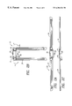
- FIG. 7A is a top plan schematic of an alternative embodiment of the invention in an expanded configuration.
- FIG. 7B is a top plan schematic of an alternative embodiment of the invention in a collapsed configuration.
- antenna 20 preferably a folded dipole, includes wire sections 12 and mutual inductance cancelling coils 10 at either end of the folded dipole.
- Wire sections 12 form the VHF element of the antenna.
- the provision of a coil in the wire serves to simulate a longer length of wire, however the provision of a single coil would result in undesired inductance.
- pairs of coils 10 one coil of a pair being wound in the opposite direction of the other of the pair, the inductance created by one coil cancels out the inductance created by the other coil. In this way, the overall length of the antenna is reduced without reducing the electrical length of the wire.
- the VHF element of the antenna is attached to printed circuit board 26 .
- a printed circuit board is employed for the UHF component.
- Printed circuit board 26 is provided with a printed UHF element 16 and an amplifier 18 .
- UHF element 16 assists in receiving transmissions in the UHF band, and amplifier IS boosts all signals that are received, be they UHF or VHF.
- Antenna 20 is connected to a receiver via cable connector 19 .
- Antenna 20 includes a main body 22 and projecting arms 24 .
- the folded dipole VHF element 12 of FIG. 6 is disposed in arms 24
- printed circuit board 26 (shown in dotted lines in FIG. 2) preferably includes UHF element 16 and amplifier 18 .
- Arms 24 are hingedly attached to main body 22 in a manner to be described below. Arms 24 are also electrically connected to main body 22 via wire sections 30 . More specifically, the long VHF element 12 disposed inside arms 24 exits arms 24 via two small holes in arms 24 and enters main body 22 via two small holes in the main body to hook up with printed circuit board 26 . Arms 24 are movable from a fully extended position as shown in FIG.
- FIG. 2A to a collapsed position as shown in FIG. 2 B.
- the arms are pivoted from their oppositely extending positions in FIG. 2A along arrows A (see FIG. 2B) to their positions in FIG. 2 B.
- the external wire section 30 of the VHF element 12 is provided with sufficient slack so that arms 24 may move freely between the two positions without putting a strain or tension on VHF element 12 .
- Main body 22 includes front housing 60 and back or rear housing 40 , both of which will be described in greater detail below. As best illustrated in FIG. 2C, front housing 60 partially covers the proximal ends of arms 24 so that external wire sections 30 are covered and protected.
- the antenna may be reduced in overall length by up to 50%. As a result, it is easier to carry, mount, install, store, transport, package, and display than conventional folded dipole antennas, since a reduced size configuration is available for the antenna.
- the antenna according to the present invention has the advantages of decreased packaging costs, decreased shipping costs, and increased storage density in a warehouse or a department store display.
- the collapsed antenna depicted in FIG. 2B is shown having arm sections extending in substantially the same direction, i.e., subtending an angle of 0°; this is the preferred embodiment of the collapsed configuration. However, as long as the arm sections in the second collapsed configuration subtend any angle less than 180°, the overall length of the antenna is reduced.
- FIGS. 3A-C Arm 24 is best illustrated in FIGS. 3A-C.
- FIG. 3A is a front plan view of the arm without its constituent electronic components
- FIG. 3C is an underside view of the front half of the housing of arm 24 ; the rear half is preferably substantially identical to the front half, and both arms are substantially identical.
- Arm 24 is provided with a central support channel 38 which adds to the structural integrity of the arm.
- support channel 38 preferably includes longitudinal ribs 37 and cross ribs 39 for strength.
- Holes 32 are provided so that the VHF wire element 12 contained in the arm can be connected to the main body 22 as discussed above. Wire element 12 passes around central support channel 38 and through holes 32 to be connected to main body 22 .
- Arm 24 is provided at its distal end with through-hole 34 .
- a hub on the main body 22 passes through through-hole 34 and allows arm 24 to be hinged or rotated in the direction of arrow A of FIG. 2 B.
- indentations or grooves 36 are provided on the inner wall of through-hole 34 in at least two groupings. Grooves 36 form part of a locking mechanism which secures arm 24 in one of at least two positions, e.g., the two positions shown in FIGS. 2A and B. The remainder of the locking mechanism will be described below.
- FIGS. 4A-D depict the rear housing 40 in front, bottom, and sectional views.
- mounting hole 42 for allowing the antenna 20 to be mounted by a nail, screw, or similar mounting device.
- the central portion of the rear housing 40 is flat and forms a recess 44 into which the PCB 26 is disposed.
- Slots 52 allow the external section 30 of wire element 12 to enter main body 22 and electrically connect with PCB 26 .
- opening 47 In a central location opposite the mounting hole 42 is provided opening 47 . Opening 47 allows cable to connect the antenna 20 to a signal receiver such as a television or to a VCR.
- landings 46 On opposite sides of rear housing 40 are provided landings 46 which support and receive the proximal ends of arms 24 . Centrally disposed in landings 46 are hubs 48 which pass through through-holes 34 of arms 24 . Support ribs 43 extend radially outward from hub 48 to provide structural integrity to landing 46 . A bore 50 is formed substantially central to hub 48 through which a screw, pin, or rivet (not shown) may pass for securing the rear housing 40 to the arm but still allowing arm 24 to rotate about hub 48 . Landings 46 , hubs 48 , and the distal ends of arms 24 are so dimensioned as to allow unobstructed rotation of arms 24 around hubs 48 as shown in FIGS. 2A-B.
- protuberances or ridges 49 are formed on the outside wall of hub 48 . These ridges 49 are dimensioned to cooperate with grooves 36 on the inner wall of through-hole 34 of arm 24 .
- Rear housing 40 may be provided with threaded holes 53 designed to receive screws (not shown); threaded holes 53 matingly align with holes 63 formed on upper housing 60 (see FIGS. 5 A-B). In this manner the front and rear housings of main body 22 may be secured together.
- the invention operates as follows.
- the purchaser receives the antenna in its packaging, preferably with the antenna configured as shown in FIG. 2B, i.e., in its collapsed configuration.
- Ridges 49 are secured in one set of grooves 36 so as to maintain arms 24 in this collapsed configuration.
- the user then mounts the antenna, for example, on the outside of his house. Once the antenna is mounted, the user overcomes the securing force of the ridges/grooves interaction (which is preferably sufficient to secure the arms in place but not so strong that a person could not manually apply enough torque to overcome it) and rotates the arms opposite to the direction of arrows A in FIG. 2 B.
- Ridges 49 on hub 48 are secured in the other set of grooves 36 corresponding to the open or extended configuration of the antenna, as shown in FIG. 2 A.
- the amplifier described as part of the printed circuit board is optional.
- the antenna is approximately 1.5 meters long, fully extended, if it is to be used for receiving television signals. However, other lengths are equally preferable if the antenna is to be used for receiving other types of signals such as FM radio transmissions.
- the locking mechanism described above utilizes one set of ridges 49 disposed on the outside of hub 48 and two sets of grooves 36 disposed on the inside of through-hole 34 .
- the ridges may be disposed on the inner wall of the through-hole of the arm and the grooves may be disposed on the hub.
- the invention may utilize two sets of ridges and one set of grooves. Again, the ridges may be disposed on either the inner wall of the through-hole or on the outside of the hub.
- the arms of the antenna may be fixed in a multiplicity of positions, i.e., positions angularly between those of FIGS. 2A and B.
- the arms may be independently movable with respect to the main body, thus allowing for an even greater number of overall configurations (e.g., one arm fully extended and the other arm at 45°, one arm at 30° and the other at 60°, etc.).
- an antenna with hinged, pivoting, or rotating arms other methods of collapsing the inventive folded dipole antenna are also contemplated.
- a folded dipole antenna with at least one arm section moving in a telescoping fashion from a first extended position to a second collapsed position.
- both arm sections would be telescoping from an extended to a collapsed position so as to significantly reduce the overall length of the device and greatly facilitate shipping, packaging, and the like.
- FIGS. 7A-B Antenna 120 is provided with a main section 122 and telescoping arms 124 .
- Arms 124 include one or more nested telescoping sections 126 which fit inside one another. Arms 124 may be collapsed into the smaller configuration of FIG. 7B from the expanded position of FIG. 7A by pushing the arms inwards in the directions of arrows B, respectively. While telescoping antennas may be known, this alternative embodiment is novel in that no folded dipole antenna has ever been made collapsible.
Landscapes
- Support Of Aerials (AREA)
- Details Of Aerials (AREA)
Abstract
Description
Claims (22)
Priority Applications (1)
| Application Number | Priority Date | Filing Date | Title |
|---|---|---|---|
| US09/158,051 US6204824B1 (en) | 1998-09-22 | 1998-09-22 | Collapsible folded dipole antenna |
Applications Claiming Priority (1)
| Application Number | Priority Date | Filing Date | Title |
|---|---|---|---|
| US09/158,051 US6204824B1 (en) | 1998-09-22 | 1998-09-22 | Collapsible folded dipole antenna |
Publications (1)
| Publication Number | Publication Date |
|---|---|
| US6204824B1 true US6204824B1 (en) | 2001-03-20 |
Family
ID=22566500
Family Applications (1)
| Application Number | Title | Priority Date | Filing Date |
|---|---|---|---|
| US09/158,051 Expired - Lifetime US6204824B1 (en) | 1998-09-22 | 1998-09-22 | Collapsible folded dipole antenna |
Country Status (1)
| Country | Link |
|---|---|
| US (1) | US6204824B1 (en) |
Cited By (11)
| Publication number | Priority date | Publication date | Assignee | Title |
|---|---|---|---|---|
| USD470837S1 (en) | 2001-09-18 | 2003-02-25 | Continental Technologies & Investments Ltd. | Waterproof, multi-use antenna |
| US6947007B1 (en) * | 2000-08-21 | 2005-09-20 | Synergy Microwave Corporation | Shortened dipole and monopole loops |
| US20060021784A1 (en) * | 2002-03-13 | 2006-02-02 | Garmong Victor H | Shielded cable entry ports and assemblies |
| US20070002547A1 (en) * | 2002-03-13 | 2007-01-04 | Garmong Victor H | Shielded enclosure with extendable mast |
| US7538742B2 (en) * | 2007-07-25 | 2009-05-26 | Trans Electric Co., Ltd. | Collapsible interior antenna |
| CN102354793A (en) * | 2011-06-17 | 2012-02-15 | 黄琼琼 | Portable rod antenna |
| CN108306090A (en) * | 2018-01-23 | 2018-07-20 | 杨瑞典 | A kind of foldable panel television antenna |
| USD855039S1 (en) | 2018-10-26 | 2019-07-30 | Pvc Antenna Inc. | Antenna |
| CN110281218A (en) * | 2019-07-08 | 2019-09-27 | 太原理工大学 | A kind of flexible hinge redundant drive parallel rigidity of structure bar |
| USD863270S1 (en) | 2018-10-31 | 2019-10-15 | PVC Antenna, Inc. | Antenna |
| CN114421119A (en) * | 2022-02-25 | 2022-04-29 | 深圳市美科星通信技术有限公司 | Antenna, wireless communication device and working method thereof |
Citations (3)
| Publication number | Priority date | Publication date | Assignee | Title |
|---|---|---|---|---|
| US3290689A (en) * | 1964-05-11 | 1966-12-06 | Packard Bell Electronics Corp | Angularly adjustable folded dipole |
| US5886669A (en) * | 1995-05-10 | 1999-03-23 | Casio Computer Co., Ltd. | Antenna for use with a portable radio apparatus |
| US5892484A (en) * | 1996-10-30 | 1999-04-06 | Amplifier Research Corporation | E-field generator |
-
1998
- 1998-09-22 US US09/158,051 patent/US6204824B1/en not_active Expired - Lifetime
Patent Citations (3)
| Publication number | Priority date | Publication date | Assignee | Title |
|---|---|---|---|---|
| US3290689A (en) * | 1964-05-11 | 1966-12-06 | Packard Bell Electronics Corp | Angularly adjustable folded dipole |
| US5886669A (en) * | 1995-05-10 | 1999-03-23 | Casio Computer Co., Ltd. | Antenna for use with a portable radio apparatus |
| US5892484A (en) * | 1996-10-30 | 1999-04-06 | Amplifier Research Corporation | E-field generator |
Cited By (17)
| Publication number | Priority date | Publication date | Assignee | Title |
|---|---|---|---|---|
| US6947007B1 (en) * | 2000-08-21 | 2005-09-20 | Synergy Microwave Corporation | Shortened dipole and monopole loops |
| USD470837S1 (en) | 2001-09-18 | 2003-02-25 | Continental Technologies & Investments Ltd. | Waterproof, multi-use antenna |
| US20060021784A1 (en) * | 2002-03-13 | 2006-02-02 | Garmong Victor H | Shielded cable entry ports and assemblies |
| US20070002547A1 (en) * | 2002-03-13 | 2007-01-04 | Garmong Victor H | Shielded enclosure with extendable mast |
| US7385147B2 (en) * | 2002-03-13 | 2008-06-10 | Pioneer Energy Products, Llc | Articulated mast |
| US7688595B2 (en) | 2002-03-13 | 2010-03-30 | Pioneer Energy Products, Llc | Shielded cable entry ports and assemblies |
| US7538742B2 (en) * | 2007-07-25 | 2009-05-26 | Trans Electric Co., Ltd. | Collapsible interior antenna |
| CN102354793B (en) * | 2011-06-17 | 2013-10-02 | 桂林长海发展有限责任公司 | Portable rod antenna |
| CN102354793A (en) * | 2011-06-17 | 2012-02-15 | 黄琼琼 | Portable rod antenna |
| CN108306090A (en) * | 2018-01-23 | 2018-07-20 | 杨瑞典 | A kind of foldable panel television antenna |
| CN108306090B (en) * | 2018-01-23 | 2024-01-30 | 杨瑞典 | Foldable flat-panel television antenna |
| USD855039S1 (en) | 2018-10-26 | 2019-07-30 | Pvc Antenna Inc. | Antenna |
| USD863270S1 (en) | 2018-10-31 | 2019-10-15 | PVC Antenna, Inc. | Antenna |
| CN110281218A (en) * | 2019-07-08 | 2019-09-27 | 太原理工大学 | A kind of flexible hinge redundant drive parallel rigidity of structure bar |
| CN110281218B (en) * | 2019-07-08 | 2022-02-15 | 太原理工大学 | Flexible hinge redundancy driving parallel structure rigidity rod |
| CN114421119A (en) * | 2022-02-25 | 2022-04-29 | 深圳市美科星通信技术有限公司 | Antenna, wireless communication device and working method thereof |
| CN114421119B (en) * | 2022-02-25 | 2024-06-07 | 深圳市美科星通信技术有限公司 | Antenna, wireless communication device and working method thereof |
Similar Documents
| Publication | Publication Date | Title |
|---|---|---|
| US6204824B1 (en) | Collapsible folded dipole antenna | |
| US4829591A (en) | Portable radio | |
| EP0613207B1 (en) | Antenna for a radio communication apparatus | |
| US3579244A (en) | Collapsible antenna employing flexible tape radiators | |
| US20170133764A1 (en) | Omni-directional television antenna with wifi reception capability | |
| JPH02127802A (en) | Telescopic antenna | |
| US6853353B2 (en) | Antenna assembly for use with a portable computing device wireless communication | |
| EP0717881A1 (en) | Aerial coupling means | |
| EP2146392A2 (en) | Marine multiband antenna | |
| JP3595856B2 (en) | Method for connecting antenna for mobile communication device and connection structure | |
| US5949384A (en) | Antenna apparatus | |
| JPS62501325A (en) | omnidirectional antenna array | |
| US4743917A (en) | Apparatus and method for a portable roll-out antenna | |
| JPH11214915A (en) | Antenna element for tv and antenna system | |
| US6181292B1 (en) | Combined UHF and VHF antenna | |
| JP4304148B2 (en) | Broadcast receiver | |
| US5657030A (en) | Collapsible single or multielement rhombic antennas | |
| US20130147671A1 (en) | Adjustable antenna system | |
| JPH0623071Y2 (en) | Antenna mounting structure for portable radios | |
| JP2002261646A (en) | Wireless transceiver | |
| JPS6031290Y2 (en) | indoor antenna | |
| JPH028421Y2 (en) | ||
| JP3852098B2 (en) | An antenna for a mobile communication terminal and a mobile communication terminal using the antenna | |
| JP2990976B2 (en) | Portable radio with external antenna | |
| JP3921980B2 (en) | High frequency signal receiver |
Legal Events
| Date | Code | Title | Description |
|---|---|---|---|
| AS | Assignment |
Owner name: RECOTON CORPORATION, FLORIDA Free format text: ASSIGNMENT OF ASSIGNORS INTEREST;ASSIGNORS:DAVI, LEONARD A.;GILBERT, HARVEY E.;REEL/FRAME:009483/0370 Effective date: 19980917 |
|
| STCF | Information on status: patent grant |
Free format text: PATENTED CASE |
|
| AS | Assignment |
Owner name: HELLER FINANCIAL, INC., ILLINOIS Free format text: SECURITY AGREEMENT;ASSIGNORS:RECOTON CORPORATION;INTERACT ACCESSORIES, INC.;AAMP OF FLORIDA, INC.;AND OTHERS;REEL/FRAME:011410/0372 Effective date: 20001031 |
|
| AS | Assignment |
Owner name: THOMSON LICENSING S.A., FRANCE Free format text: ASSIGNMENT OF ASSIGNORS INTEREST;ASSIGNOR:RECOTON CORPORATION;REEL/FRAME:014268/0101 Effective date: 20030710 |
|
| FPAY | Fee payment |
Year of fee payment: 4 |
|
| FPAY | Fee payment |
Year of fee payment: 8 |
|
| FPAY | Fee payment |
Year of fee payment: 12 |