US6158091A - Drafting frame for a spinning machine having a roving compactor - Google Patents
Drafting frame for a spinning machine having a roving compactor Download PDFInfo
- Publication number
- US6158091A US6158091A US09/390,534 US39053499A US6158091A US 6158091 A US6158091 A US 6158091A US 39053499 A US39053499 A US 39053499A US 6158091 A US6158091 A US 6158091A
- Authority
- US
- United States
- Prior art keywords
- belt
- roving
- drafting frame
- stripper
- edge
- Prior art date
- Legal status (The legal status is an assumption and is not a legal conclusion. Google has not performed a legal analysis and makes no representation as to the accuracy of the status listed.)
- Expired - Lifetime
Links
Images


Classifications
-
- D—TEXTILES; PAPER
- D01—NATURAL OR MAN-MADE THREADS OR FIBRES; SPINNING
- D01H—SPINNING OR TWISTING
- D01H5/00—Drafting machines or arrangements ; Threading of roving into drafting machine
- D01H5/18—Drafting machines or arrangements without fallers or like pinned bars
- D01H5/60—Arrangements maintaining drafting elements free of fibre accumulations
- D01H5/62—Non-rotary cleaning pads or plates; Scrapers
Definitions
- Our present invention relates to a drafting frame for a machine for processing a roving, e.g. a roving frame or spinning machine, (especially a ring-spinning machine wherein the drafting frame has at least at its output a compacting unit which can subject the previously drafted roving or band to compaction before the roving is fed to the roving frame.
- a roving frame or spinning machine especially a ring-spinning machine wherein the drafting frame has at least at its output a compacting unit which can subject the previously drafted roving or band to compaction before the roving is fed to the roving frame.
- the compaction unit may be an endless belt formed downstream of the last of the drafting members of the series of codirectionally moving surfaces (rollers or belts) which are spaced apart along the path of the roving and which are driven at progressively increased peripheral speeds to draft the roving.
- a belt When such a belt is used as a compaction unit, it may be provided with a perforation, e.g. a row of orifices extending along the path of the roving or a slit and under suction so that the fibers of the drafted roving or fiber band are drawn together and thereby compacted as they pass between this belt and a surface of another belt or roller moving in the same direction.
- the belt may enclose a suction chamber which is maintained under subatmospheric pressure.
- Such a wiping roller may have a felt or other pile surface and hence the wiped off fibers can collect on this roller and require a removal or replacement of the roller from time to time.
- the accumulation thereon may damage the drafting frame at the station at which the roving may be supplied and at adjacent stations, can interfere with proper roving feed to the spinning stations and may otherwise be detrimental to the spinning operation. Indeed, it can cause breakage of neighboring spun threads.
- German Patent Document 1,760,832 which has a cleaning device in which a cleaning edge is provided along a roller and along a belt for removing collected fiber in conjunction with a drafting frame. This system does not operate fully satisfactorily, although it does provide two or more edges on a common support and hence simplified mounting of the cleaning system.
- the principal object of the present invention to provide a drafting frame with at least one roving compaction unit whereby the aforedescribed drawbacks are avoided and high quality thread can be produced at high efficiency.
- Another object of the invention is to provide a roving frame in which detrimental aspects of fiber accumulation on a compaction belt, excessive friction of the roving belt and the need for repeated replacement of cleaning rollers can all be obviated.
- a stripper having a stripping edge extending a full width of the belt and juxtaposed with the belt over a convex portion thereof across a gap, for stripping fibers accumulating on the belt from the belt;
- a suction device having a mouth proximal to the stripper for evacuating away fibers stripped from the belt.
- the stripping edge is formed by flanks adjoining (converging) at an acute angle.
- the perforation means which can be a continuous slit or a number of spaced apart perforations, e.g. a row of orifices, can be juxtaposed with a portion of the stripping edge which is formed with a recess in the region of the perforations, i.e. is set back, the remainder of the stripping edge approaching the surface of the belt quite closely on either side of this recess.
- an essential feature of the invention is the maintenance of a gap between the stripping edge and the belt surface with which it is juxtaposed so that there is no friction of the stripping edge against that belt surface.
- the gap may be relatively small, ranging from a fraction of a millimeter (say 0.2 mm) to several millimeters (say 4 mm).
- means for adjusting the spacing between the edge and the belt. That means can include means for mounting the stripper for swing movement for swinging movement relative to the belt.
- the suction device itself is constructed so that its suction is effective over the entire length of the stripping edge.
- the suction device can be connected to the suction source for the compaction units and can have a mouth positioned so that it is effective over the entire length of the stripping edge although a separate suction source can be provided for the stripper suction heads. Because of the spacing of the stripper from the belt, damage to the belt at the perforations by the stripper can be avoided.
- the stripper act at a convex part of the path of the belt and preferably at a narrow or small radius portion wherein the belt is guided over a deflecting rail.
- the stripper can be juxtaposed with that part of the belt running around the drum which drives the belt.
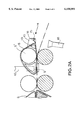
- FIG. 1 is a cross sectional view through a drafting frame according to the invention
- FIG. 1A is a detail of FIG. 1;
- FIG. 2 is a view similar to FIG. 1 through a drafting frame in accordance with the invention
- FIG. 2A is a detail of FIG. 2;
- FIG. 3 is a detail view of the stripping unit as seen from below.
- a drafting frame 1 which can be supplied with roving R comprises four roller pairs 2, 3, 4 and 5 in succession.
- the rollers 2', 3', 4' 5' of these roller pairs form the lower rollers and may be continuous over the length of a roving frame or spinning machine and can be driven at their ends at progressively higher speeds to apply the drafting action to respective rovings R to be fed to respective spindles at respective stations of the spinning frame.
- the upper rollers 2", 3", 4" and 5" may be carried in arms (not shown) which can be raised and lowered and which are weighted to press the roving against the lower rollers as is conventional in drafting frames.
- a predrafting stretch 12 can be provided while between the roller pairs 3 and 4, a main drafting stretch 12' can be maintained.
- the rollers 3' and 3" are encircled by respective belts 6' and 6 which have appropriate guides and which form the surfaces between which the roving R or the drafted strand or fiber band passes.
- a further zone 12" can be provided between the roller pairs 4 and 5 and the output roller pair 5 may form a compaction unit. In the compacting zone 12" there is no drafting of the band. Generically a compaction unit at the end of the drafting frame is represented at 7.
- compaction unit is here used to describe a unit in which stray fibers and filaments are drawn toward the center of the roving so that the number of fibers or filaments which project from the roving per unit length is substantially reduced.
- a compaction unit can comprise a perforation means along a line communicating between a suction chamber and the roving and formed by a row of perforations or a slit.
- the output roller pair 5 forms just such a compaction unit 7 which comprises a compaction belt 8 which surrounds and delimits a suction chamber 9.
- the suction chamber 9 is connected by piping or a hose 10 with a suction source not shown. At the compaction unit drafting does not occur.
- the compaction belt 8 is provided centrally with a row of perforations 11 forming the perforation means (see FIG. 3), these perforations or orifices are under suction from the reduced pressure in chamber 9 and draw fibers which tend to project laterally from the roving toward the center of the roving to compact the latter.
- a cage 13 which is not shown in detail is mounted to be swingable about an arrow 13' and carries a stripping edge 16 defined between flanks 16a, 16b at an acute angle 16c to one another and adjustable by a screw or a servomechanism represented at 13n and forming adjustment means.
- the cage and stripping blade form a stripper unit represented at 14, the blade itself being carried by a pin 15 which is swingable as represented by the arrow 13' previously mentioned.
- the stripping edge 16 extends the full length of the roller 5" and hence substantially the full width of the belt 8 and is spaced from the belt by a slit gap which is difficult to discern in the drawing because of the scale used. That gap is adjustable by the means 13".
- a cut-out 17 can be provided in the stripping edge 16 so that edge portions 16' approach but are spaced from the belt to either side of that recess as shown at 16' in FIG. 3, by the gap.
- a suction pipe 18 has a mouth 18' which also can extend the full length of the roller 5" and the full width of the belt 8 to collect lint and fiber which are stripped by the edge 16 from the belt.
- the mouth 18' is thus effective so that its suction can collect all of the lint which is removed by the strippers 14 from the respective belts.
- the embodiment of FIGS. 2 and 2A differs from that of FIG. 1 only in that the compaction belt 8 is also guided downstream of the roller 5" by a rail 19 and has a small radius deflection at which the stripping blade 16 approaches the belt.
- the blade is effective in a region in which the belt is convexly curved promotes the stripping effect and that effect is further promoted by guiding the belt over a guide rail of a reduced radius of curvature in the region in which the stripper is provided.
Landscapes
- Engineering & Computer Science (AREA)
- Mechanical Engineering (AREA)
- Textile Engineering (AREA)
- Spinning Or Twisting Of Yarns (AREA)
Abstract
Description
Claims (6)
Applications Claiming Priority (2)
| Application Number | Priority Date | Filing Date | Title |
|---|---|---|---|
| DE19840960 | 1998-09-08 | ||
| DE19840960A DE19840960B4 (en) | 1998-09-08 | 1998-09-08 | Drafting system for spinning machines with a compacting device |
Publications (1)
| Publication Number | Publication Date |
|---|---|
| US6158091A true US6158091A (en) | 2000-12-12 |
Family
ID=7880207
Family Applications (1)
| Application Number | Title | Priority Date | Filing Date |
|---|---|---|---|
| US09/390,534 Expired - Lifetime US6158091A (en) | 1998-09-08 | 1999-09-03 | Drafting frame for a spinning machine having a roving compactor |
Country Status (4)
| Country | Link |
|---|---|
| US (1) | US6158091A (en) |
| EP (1) | EP0985754B1 (en) |
| JP (1) | JP2000096358A (en) |
| DE (2) | DE19840960B4 (en) |
Cited By (6)
| Publication number | Priority date | Publication date | Assignee | Title |
|---|---|---|---|---|
| US6272834B1 (en) * | 1999-05-12 | 2001-08-14 | SPINDELFABRIK SüSSEN, SCHURR, STAHLECKER & GRILL GMBH | Apparatus for condensing a drafted fiber strand |
| US6298523B1 (en) * | 1999-11-18 | 2001-10-09 | Fritz Stahlecker | Apparatus for condensing a fiber strand and a method of making yarn using same |
| US6332244B1 (en) * | 1999-11-26 | 2001-12-25 | Marzoli S.P.A. | Method and apparatus for drafting and condensing a roving, particularly an a ring spinning frame |
| US6341484B2 (en) * | 2000-02-24 | 2002-01-29 | Zinser Textilmaschinen Gmbh | Drafting frame for a spinning machine |
| US6604261B2 (en) * | 2001-06-08 | 2003-08-12 | Zinser Textilmaschinen Gmbh | Drafting frame for a spinning machine |
| US20200248341A1 (en) * | 2019-02-04 | 2020-08-06 | Itoi Lifestyle Research Co. | Japanese paper yarn manufacturing device and japanese paper yarn manufacturing method |
Families Citing this family (1)
| Publication number | Priority date | Publication date | Assignee | Title |
|---|---|---|---|---|
| DE102009038267A1 (en) | 2009-08-20 | 2011-02-24 | Rotorcraft Ag | Fiber guide for guiding fiber bundle into inlet of roller pair in drawing frame of spinning machine, has integrated magnetic elements for pressing guide against lower roller of output roller pair of drawing frame during operation of frame |
Citations (12)
| Publication number | Priority date | Publication date | Assignee | Title |
|---|---|---|---|---|
| US3141203A (en) * | 1958-12-31 | 1964-07-21 | Ideal Ind | Method and means for clearing textile rolls |
| US3251101A (en) * | 1964-02-06 | 1966-05-17 | Deering Milliken Res Corp | Suction clearer |
| DE1251194B (en) * | 1967-09-28 | |||
| DE1760832A1 (en) * | 1968-07-06 | 1972-03-09 | Zinser Textilmaschinen Gmbh | Cleaning device for drafting elements |
| US3802174A (en) * | 1970-08-26 | 1974-04-09 | Schubert & Salzer Maschinen | Method and apparatus for producing of staple fibre yarn |
| US3992865A (en) * | 1974-10-09 | 1976-11-23 | Toray Industries, Inc. | Method and apparatus to start interrupt and stop spinning of a fasciated spun yarn |
| US4662167A (en) * | 1985-03-15 | 1987-05-05 | Hans Stahlecker | Spinning machine maintenance unit with fly catching needle |
| US4953349A (en) * | 1988-09-29 | 1990-09-04 | Ernst Fehrer | Apparatus for making a yarn |
| US5090192A (en) * | 1989-08-23 | 1992-02-25 | Hans Stahlecker | Process and an arrangement for false-twist spinning |
| US5305498A (en) * | 1990-11-21 | 1994-04-26 | Fritz Stahlecker | Arrangement for cleaning a pressure roller of a drafting unit |
| DE4323472A1 (en) * | 1993-07-14 | 1995-01-19 | Inst F Textil Und Verfahrenste | Double apron drafting system |
| DE29600417U1 (en) * | 1996-01-11 | 1996-03-07 | Zinser Textilmaschinen Gmbh, 73061 Ebersbach | Drafting system for a spinning machine |
Family Cites Families (2)
| Publication number | Priority date | Publication date | Assignee | Title |
|---|---|---|---|---|
| US4274179A (en) * | 1979-06-18 | 1981-06-23 | Progressive Equipment, Inc. | Spinning frame apron clearer attachment |
| US5400583A (en) * | 1992-05-22 | 1995-03-28 | The De Williams Company | Yarn lap preventor for a take-up shaft in open end spinning machine |
-
1998
- 1998-09-08 DE DE19840960A patent/DE19840960B4/en not_active Expired - Fee Related
-
1999
- 1999-09-02 JP JP11248585A patent/JP2000096358A/en not_active Withdrawn
- 1999-09-03 DE DE59905155T patent/DE59905155D1/en not_active Expired - Lifetime
- 1999-09-03 EP EP99117320A patent/EP0985754B1/en not_active Expired - Lifetime
- 1999-09-03 US US09/390,534 patent/US6158091A/en not_active Expired - Lifetime
Patent Citations (13)
| Publication number | Priority date | Publication date | Assignee | Title |
|---|---|---|---|---|
| DE1251194B (en) * | 1967-09-28 | |||
| US3141203A (en) * | 1958-12-31 | 1964-07-21 | Ideal Ind | Method and means for clearing textile rolls |
| US3251101A (en) * | 1964-02-06 | 1966-05-17 | Deering Milliken Res Corp | Suction clearer |
| DE1760832A1 (en) * | 1968-07-06 | 1972-03-09 | Zinser Textilmaschinen Gmbh | Cleaning device for drafting elements |
| US3802174A (en) * | 1970-08-26 | 1974-04-09 | Schubert & Salzer Maschinen | Method and apparatus for producing of staple fibre yarn |
| US3992865A (en) * | 1974-10-09 | 1976-11-23 | Toray Industries, Inc. | Method and apparatus to start interrupt and stop spinning of a fasciated spun yarn |
| US4662167A (en) * | 1985-03-15 | 1987-05-05 | Hans Stahlecker | Spinning machine maintenance unit with fly catching needle |
| US4953349A (en) * | 1988-09-29 | 1990-09-04 | Ernst Fehrer | Apparatus for making a yarn |
| US5090192A (en) * | 1989-08-23 | 1992-02-25 | Hans Stahlecker | Process and an arrangement for false-twist spinning |
| US5305498A (en) * | 1990-11-21 | 1994-04-26 | Fritz Stahlecker | Arrangement for cleaning a pressure roller of a drafting unit |
| DE4323472A1 (en) * | 1993-07-14 | 1995-01-19 | Inst F Textil Und Verfahrenste | Double apron drafting system |
| US5600872A (en) * | 1993-07-14 | 1997-02-11 | Artzt; Peter | Double-belt draw frame |
| DE29600417U1 (en) * | 1996-01-11 | 1996-03-07 | Zinser Textilmaschinen Gmbh, 73061 Ebersbach | Drafting system for a spinning machine |
Cited By (6)
| Publication number | Priority date | Publication date | Assignee | Title |
|---|---|---|---|---|
| US6272834B1 (en) * | 1999-05-12 | 2001-08-14 | SPINDELFABRIK SüSSEN, SCHURR, STAHLECKER & GRILL GMBH | Apparatus for condensing a drafted fiber strand |
| US6298523B1 (en) * | 1999-11-18 | 2001-10-09 | Fritz Stahlecker | Apparatus for condensing a fiber strand and a method of making yarn using same |
| US6332244B1 (en) * | 1999-11-26 | 2001-12-25 | Marzoli S.P.A. | Method and apparatus for drafting and condensing a roving, particularly an a ring spinning frame |
| US6341484B2 (en) * | 2000-02-24 | 2002-01-29 | Zinser Textilmaschinen Gmbh | Drafting frame for a spinning machine |
| US6604261B2 (en) * | 2001-06-08 | 2003-08-12 | Zinser Textilmaschinen Gmbh | Drafting frame for a spinning machine |
| US20200248341A1 (en) * | 2019-02-04 | 2020-08-06 | Itoi Lifestyle Research Co. | Japanese paper yarn manufacturing device and japanese paper yarn manufacturing method |
Also Published As
| Publication number | Publication date |
|---|---|
| JP2000096358A (en) | 2000-04-04 |
| DE19840960B4 (en) | 2004-05-19 |
| DE19840960A1 (en) | 2000-03-09 |
| EP0985754A1 (en) | 2000-03-15 |
| DE59905155D1 (en) | 2003-05-28 |
| EP0985754B1 (en) | 2003-04-23 |
Similar Documents
| Publication | Publication Date | Title |
|---|---|---|
| US5600872A (en) | Double-belt draw frame | |
| US20010020357A1 (en) | Drafting frame for a spinning machine | |
| US5522119A (en) | Fiber web supporting device in a carding machine | |
| US6158091A (en) | Drafting frame for a spinning machine having a roving compactor | |
| CN211227453U (en) | Fiber multi-roller drafting equipment | |
| US4274178A (en) | Device for stripping a fibrous web from a doffer in a carding machine | |
| CN1416483A (en) | Device for compressing fiber assembly in spinning machine | |
| US2430611A (en) | Drawing mechanism for spinning and roving frames | |
| US3825975A (en) | Apparatus for forming a sliver from a fiber web produced in a card | |
| US5761773A (en) | Textile machine fleece funnel | |
| KR100589880B1 (en) | Fiber bundle collecting device for a spinning machine | |
| GB2089845A (en) | Drafting method and apparatus in spinning machine | |
| US5327617A (en) | Electrostatic opening and short fiber separation apparatus for carding machines | |
| EP0076087A1 (en) | Method and apparatsu for forming a sliver | |
| US5839165A (en) | Textile machine | |
| US6604261B2 (en) | Drafting frame for a spinning machine | |
| CN110621818B (en) | Carding machine | |
| US6112509A (en) | Drafting equipment with small double belts | |
| CN1453404A (en) | Apparatus for gathering one fiber sliver at a spinning machine | |
| US4926627A (en) | Device to feed and open a fiber sliver on an open-end spinning device | |
| US3838476A (en) | Drawing frame | |
| US3141203A (en) | Method and means for clearing textile rolls | |
| KR100555188B1 (en) | Fiber bundle collecting device of a spinning machine | |
| US3251100A (en) | Drafting system with top and bottom roll cleaning | |
| JPH0340128B2 (en) |
Legal Events
| Date | Code | Title | Description |
|---|---|---|---|
| AS | Assignment |
Owner name: ZINSER TEXTILMASCHINEN GMBH, GERMANY Free format text: ASSIGNMENT OF ASSIGNORS INTEREST;ASSIGNORS:OLBRICH, ANDREAS;KRAWIETZ, STEFAN;SCHNEIDER, JURGEN;AND OTHERS;REEL/FRAME:010445/0928;SIGNING DATES FROM 19991105 TO 19991201 |
|
| STCF | Information on status: patent grant |
Free format text: PATENTED CASE |
|
| FEPP | Fee payment procedure |
Free format text: PAYOR NUMBER ASSIGNED (ORIGINAL EVENT CODE: ASPN); ENTITY STATUS OF PATENT OWNER: LARGE ENTITY |
|
| FEPP | Fee payment procedure |
Free format text: PAYOR NUMBER ASSIGNED (ORIGINAL EVENT CODE: ASPN); ENTITY STATUS OF PATENT OWNER: LARGE ENTITY Free format text: PAYER NUMBER DE-ASSIGNED (ORIGINAL EVENT CODE: RMPN); ENTITY STATUS OF PATENT OWNER: LARGE ENTITY |
|
| FPAY | Fee payment |
Year of fee payment: 4 |
|
| FPAY | Fee payment |
Year of fee payment: 8 |
|
| FPAY | Fee payment |
Year of fee payment: 12 |
|
| AS | Assignment |
Owner name: SAURER GMBH & CO. KG, GERMANY Free format text: MERGER;ASSIGNOR:ZINSER TEXTILMASCHINEN GMBH;REEL/FRAME:031620/0862 Effective date: 20030819 |
|
| AS | Assignment |
Owner name: OERLIKON TEXTILE GMBH & CO. KG, GERMANY Free format text: CHANGE OF NAME;ASSIGNOR:SAURER GMBH & CO. KG;REEL/FRAME:032125/0949 Effective date: 20070605 |
|
| AS | Assignment |
Owner name: SAURER GERMANY GMBH & CO. KG., GERMANY Free format text: ASSIGNMENT OF ASSIGNORS INTEREST;ASSIGNOR:OERLIKON TEXTILE GMBH & CO. KG;REEL/FRAME:032170/0024 Effective date: 20131011 |