US6148733A - Type E railway coupler with expanded gathering range - Google Patents
Type E railway coupler with expanded gathering range Download PDFInfo
- Publication number
- US6148733A US6148733A US09/097,437 US9743798A US6148733A US 6148733 A US6148733 A US 6148733A US 9743798 A US9743798 A US 9743798A US 6148733 A US6148733 A US 6148733A
- Authority
- US
- United States
- Prior art keywords
- gathering
- coupler
- freight car
- vertical
- type
- Prior art date
- Legal status (The legal status is an assumption and is not a legal conclusion. Google has not performed a legal analysis and makes no representation as to the accuracy of the status listed.)
- Expired - Lifetime
Links
Images


Classifications
-
- B—PERFORMING OPERATIONS; TRANSPORTING
- B61—RAILWAYS
- B61G—COUPLINGS; DRAUGHT AND BUFFING APPLIANCES
- B61G3/00—Couplings comprising mating parts of similar shape or form which can be coupled without the use of any additional element or elements
- B61G3/04—Couplings comprising mating parts of similar shape or form which can be coupled without the use of any additional element or elements with coupling head having a guard arm on one side and a knuckle with angularly-disposed nose and tail portions pivoted to the other side thereof, the nose of the knuckle being the coupling part, and means to lock the knuckle in coupling position, e.g. "A.A.R." or "Janney" type
Definitions
- This invention relates generally to a new and improved Type E railway freight car coupler having an expanded gathering range. More particularly, this invention relates to a new and improved Type E railway freight car coupler which is modified only slightly and cheaply from conventional Type E railway freight car couplers to include an extension wing which will provide an expanded gathering range, and relates further to an extension wing for retro-fitting onto a conventional Type E railway freight car coupler for converting such a prior art coupler to a coupler of this invention, and relates further to the process for making such a retro-fitted conversion.
- the Type E coupler was adopted as the ARA, American Railway Association (predecessor to the AAR, Association of American Rails) standard coupler for railway freight cars. Although modified periodically since then to meet changing requirements imposed by changing demands, and other coupler designs have been developed for special applications, the Type E coupler is today still the standard coupler for freight service.
- the standard coupler all producers of such couplers in the United States are required to produce the couplers to the standard specification, at least for use within the USA, so that such couplers are not only completely interchangeable, regardless of the manufacturer, but more importantly, so that the couplers from any manufacturer can readily be joined to couplers from any other domestic manufacturer.
- the Type E coupler is well known to those knowledgeable in the trade as having a pivotal, vertical-knuckle adapted to engage an identical vertical-knuckle on an adjacent coupler, so that when the couplers are brought into contact with each other, the two knuckles are pivoted into an interlocking, engaging position.
- Each coupler includes a gravity activated coupler lock member adapted to slide downwardly after coupler engagement to virtually lock each knuckle at it's engaged position. To permit the coupler to become disengaged, each coupler lock member must be raised within its slide-channel, so that a draft load on the couplers tending to pull the cars apart, will cause the knuckles to pivot away from each other, thereby becoming disengaged.
- the Type E railway coupler further includes a cast steel coupler head at the forward end extending from a shank which is fitted within and attached to a yoke, which secures the shank end of the coupler to the railway car.
- the forward end of the coupler head is generally V-shaped in horizontal cross-section with the "V" opening facing outwardly from an end of the railway car with the above-described vertical-knuckle pinned at one side to form one leg of the "V".
- the other leg of the "V" comprises a fixed and rigid gathering arm, specifically, a forwardly extending head portion extending at an angle to the coupler center line and having an angled, inside gathering surface against which the vertical-knuckle on a mating coupler is intended to impact and be pivoted inwardly to a degree sufficient: to activate the lock and thereby be locked in place. Therefore, as a pair of such railway cars, and particularly a pair of such couplers, are brought together for coupling them together, the two opposed vertical-knuckles will contact the angled gathering surface on the adjacent coupler's gathering arm and be pivoted inwardly behind each other, thereby engaging each other and locking the two couplers together, as above-described.
- These and other operating parts of the Type E railway coupler are well known to those familiar with the art and have been since 1932, so that a further detailed description is not believed to be necessary here.
- the coupler shanks are pivotally secured to the railway car, so that pursuant to AAR specification, each coupler shank can pivot 13° in a horizontal plan to either side of the longitudinal center line of the railway car. Therefore, to readily join a pair of freight railroad cars together, it may be necessary to pivot the coupler shanks so that the coupler heads are generally aligned and directly opposed from each other. While proper straight alignment may naturally result when a pair of cars are disjoined while on a length of straight track, there are times, however, when they are not properly aligned for joining.
- the couplers when a pair of cars are disjoined while oil a curved track the couplers will not normally extend perpendicularly from the end of the railway car.
- the coupler shanks are preferably not oriented perpendicularly from the ends of the car to be joined. Accordingly, it may be necessary for an operator or trainman to manually position the coupler or couplers by pushing or pulling it or them into proper alignment before the cars can successfully be joined together by moving one into the other. If attempts to join a pair of railway cars are made when the couplings are not properly aligned, the impact of misaligned couplers may cause damage to one or both couplers.
- This invention is predicated on the development of a new and improved Type E railway freight car coupler having an enhanced gathering range which will more readily permit the coupling of a pair of adjacent railway cars regardless of the pivotal orientation of the couplers, and also more readily permit the coupling of a pair of adjacent railway cars sitting on a length of curved track.
- the coupler of this invention is substantially identical to the Type E coupler of the prior art, except that the head portion of the inventive coupler is provided with a rigid extension wing extending outwardly from the end of the gathering arm to provide an extension of the angled gathering surface so that the extended gathering surface will more readily engage the pivotal knuckle of the adjacent coupler when the couplers are brought together while not properly aligned with each other.
- the coupler of this invention will in no way adversely affect a normal coupling action whereby the couplers extend perpendicularly from the ends of the railway cars pursuant to more normal practices, and can readily be joined to a conventional, prior art coupler not having such an extension wing.
- a primary object of this invention is to provide a new and improved Type E railway freight car coupler having an enhanced gathering range.
- Another primary object of this invention is to provide a Type E railway freight car coupler having an enhanced gathering range which will more readily permit the coupling of a pair of adjacent railway cars regardless of the pivotal orientation of the couplers.
- a further primary object of this invention is to provide a Type E railway freight car coupler having an enhanced gathering range which will more readily permit the coupling of a pair of adjacent railway cars sitting on a length of curved track.
- Still another primary object of this invention is to provide a Type E railway freight car coupler having an extension wing extending angularly outward from the coupler's gathering arm to provide an enhanced gathering range which will more readily permit the coupling of a pair of adjacent railway cars regardless of the pivotal orientation of the coupler heads.
- An even further object of this invention is to provide an extension wing for attachment to a conventional Type E railway freight car coupler to provide the coupler with an enhanced gathering range which will more readily permit the coupling of a pair of adjacent railway cars regardless of the pivotal orientation of the coupler heads.
- Yet an even further object of this invention is to provide a method of retr-ofitting a conventional Type E railway freight car coupler with an extension wing to enhance the coupler's gathering range, to thereby permit the coupling of a pair of adjacent railway cars regardless of the pivotal orientation of the coupler heads.
- FIG. 1 is a plan view of a prior art Type E railway freight car coupler.
- FIG. 2 is a right-side elevational view of the prior art Type E railway freight car coupler shown in FIG. 1.
- FIG. 3 is a left-side elevational view of the prior art Type E railway freight car coupler shown in FIGS. 1 and 2.
- FIG. 4 is a plan view of a Type E railway freight car coupler having an expanded gathering range according to a presently preferred embodiment of this invention.
- FIG. 5 is a right-side elevational view of the inventive Type E railway freight car coupler shown in FIG. 4.
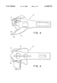
- FIG. 6 is a plan view of an extension wing for retro-fitting onto a prior art Type E railway freight car coupler for converting such prior art coupler to a coupler of this invention.
- FIG. 7 is a right-side edge view of the extension wing shown in FIG. 6.
- FIG. 8 is a plan view of a prior art Type E railway freight car coupler having an extension wing as shown in FIGS. 6 and 7 retro-fitted onto the gathering arm to expand its gathering range according to another presently preferred embodiment of this invention.
- FIG. 9 is a right-side elevational view of the retro-fitted Type E railway freight car coupler shown in FIG. 8.
- FIGS. 1-3 will illustrate a conventional, prior art Type E coupler for freight railway cars as required by the AAR, and generally designated 10, which is intended for mounting within a yoke (not shown) secured at each end of a railway car center sill (not shown), such that one each coupler extends outwardly under each end of the railway car at the center line.
- the coupler 10 includes a generally V-shaped coupler head 12 at a forward end thereof extending from a shank 20 adapted to be fitted within and attached to a yoke (not shown) secured at each end of the center sill (not shown) which extends full length under the railway car (not shown) at the longitudinal axis.
- the generally V-shaped coupler head 12 has a vertical-knuckle 14 rotatably pinned at an outer end of coupler head 12 forming a first leg of the generally V-shaped coupler head 12, while a second leg of the generally V-shaped coupler head 12 comprises a fixed and rigid gathering arm 16 having a first angled gathering surface 18 against which a vertical-knuckle 14 on a mating coupler (not shown but like coupler 10) is intended to impact when two adjacent railway cars are brought together.
- the two railway cars should preferably be sitting on a straight length of track, and the two couplers, like coupler 10, should preferably be at least generally oriented parallel to the track and perpendicular to the end of the railway car to face each other to assure a proper coupling.
- the crux of this invention is to provide a coupler in which the two last above-noted requirements are not essential, and particularly to provide a coupler which can readily be joined to a like coupler when the railway cars to which they are mounted are sitting on a length of curved track, or are otherwise not properly aligned with each other.
- Reference to FIGS. 4 and 5 will illustrate a presently preferred embodiment of the new and unique coupler 10' of this invention, which for all intents and purposes, is substantially identical to a conventional Type E coupler 10 described above with reference to FIGS. 1-3, except for the fact that coupler 10' includes an extension wing 30, extending angularly outwardly at least about 6 inches from the outer end of gathering arm 16.
- Extension wing 30 further includes a gathering surface extension 32, which extends angularly outward from gathering surface 18 to virtually create an elongated gathering surface 18-32.
- the inventive coupler having an expanded gathering range is essentially the same as a prior art coupler except that it has an elongated gathering arm together with an extension to the gathering surface, extending outwardly at least about 6 inches in a direction generally parallel to the gathering surface.
- the elongated gathering arm comprises gathering arm 16 plus extension wing 30 to form gathering arm 16-30
- the elongated gathering surface comprises gathering surface 18 plus gathering surface extension 32 to form elongated gathering surface 18-32.
- the extended gathering surface 18-32 will contact and engage an opposed vertical knuckle 14 even when the two opposed couplers 10' are not directly opposed from each other, and even when each coupler shank 20 is pivoted in opposite directions.
- an additional embodiment of this invention includes an independently cast extension wing 30a as shown in FIGS. 5 and 6 for attachment by welding or otherwise onto a conventional, prior art gathering arm 16, thereby retro-fitting such a conventional prior art coupler to be in accordance with the inventive coupler having an enhanced gathering range, pursuant to this invention.
- Reference to FIGS. 6 and 7 will illustrate a presently preferred embodiment of such an extension wing, generally designated 30a.
- Extension wing 30a is a three-dimensional body of cast steel or the like, which includes a first surface 32a, which is intended to form the extension of gathering surface 18.
- a second surface 34 has a predetermined configuration which is adapted to be joined onto the end of gathering arm 16. While the other surfaces of extension wing 30a are not particularly critical, they should preferably be designed to provide an extension of the peripheral surfaces of gathering arm 16 from which they extend, and provide sufficient mass to the extension wing 30a to effect an adequate impact strength to assure that it is not fractured during coupling.
- a currently preferred method is to provide second surface 34 on extension wing 30a with a concave or right-angled configuration adapted to mate with the existing outer end of gathering arm 16.
- the periphery of second surface 34 is provided with a angled taper for the purposes of facilitating welding.
- the weld surfaces, and particularly the weld surface at gathering surface 18a-32a should be ground to provide a smooth surface transition between the joined components so that a vertical knuckle 14 on an adjacent coupler will slidably move from along the elongated gathering surface 18a-32a without any hang-up or interference by the interface.
- An alternate method would be to provide a second surface as a flat surface on extension wing 30a generally transverse to surface 32a.
- the tip portion of gathering arm 16 is cut-off, as with a cutting torch, saw or the like, to effect a resulting cut surface on gathering arm 16 that will be of a size and configuration adapted to mate with flat second surface 34.
- flat surface 34 can then be welded onto the flat cut surface on gathering arm 16.
- a tapered periphery around surface 34 may be desired to facilitate welding.
- weld surfaces, and particularly the weld surface at gathering surface 18a-32a should be ground to provide a smooth surface transition between the joined components so that a vertical knuckle 14 on an adjacent coupler will slidably move along the elongated gathering surface without any hang-ups or interference by the interface.
- the first surface of the extension wing 30a can, if desired, be shaped to a concave form adapted to generally match the convex tip of the gathering arm 16 with the two components joined by a thermite welding procedure.
- interface surfaces other than flat or concave-convex can be formed such as tongue-in-groove like interfaces.
- other welding techniques could be utilized with equal or perhaps even better results. Accordingly, a number of different embodiments could be developed in both the extension wing and method of joining it to a prior art coupler could be made without departing from the spirit of the invention.
Landscapes
- Engineering & Computer Science (AREA)
- Mechanical Engineering (AREA)
- Toys (AREA)
- Bridges Or Land Bridges (AREA)
- Fittings On The Vehicle Exterior For Carrying Loads, And Devices For Holding Or Mounting Articles (AREA)
Abstract
Description
Claims (9)
Priority Applications (3)
| Application Number | Priority Date | Filing Date | Title |
|---|---|---|---|
| US09/097,437 US6148733A (en) | 1998-06-15 | 1998-06-15 | Type E railway coupler with expanded gathering range |
| AU35056/99A AU3505699A (en) | 1998-06-15 | 1999-06-15 | Type E railway coupler with expanded gathering range |
| CA002274981A CA2274981C (en) | 1998-06-15 | 1999-06-15 | Type e railway coupler with expanded gathering range |
Applications Claiming Priority (1)
| Application Number | Priority Date | Filing Date | Title |
|---|---|---|---|
| US09/097,437 US6148733A (en) | 1998-06-15 | 1998-06-15 | Type E railway coupler with expanded gathering range |
Publications (1)
| Publication Number | Publication Date |
|---|---|
| US6148733A true US6148733A (en) | 2000-11-21 |
Family
ID=22263341
Family Applications (1)
| Application Number | Title | Priority Date | Filing Date |
|---|---|---|---|
| US09/097,437 Expired - Lifetime US6148733A (en) | 1998-06-15 | 1998-06-15 | Type E railway coupler with expanded gathering range |
Country Status (3)
| Country | Link |
|---|---|
| US (1) | US6148733A (en) |
| AU (1) | AU3505699A (en) |
| CA (1) | CA2274981C (en) |
Cited By (13)
| Publication number | Priority date | Publication date | Assignee | Title |
|---|---|---|---|---|
| US20080128377A1 (en) * | 2006-12-05 | 2008-06-05 | Mautino P Scott | Railcar Coupler System and Method |
| WO2010033661A1 (en) * | 2008-09-17 | 2010-03-25 | Mcconway & Torley, Llc | Railcar coupler system and method |
| US20110068077A1 (en) * | 2009-09-21 | 2011-03-24 | Strato, Inc. | Knuckle for a railway car coupler |
| US8196762B2 (en) | 2008-05-23 | 2012-06-12 | Bedloe Industries Llc | Knuckle formed without a finger core |
| US8201613B2 (en) | 2008-05-23 | 2012-06-19 | Bedloe Industries Llc | Knuckle formed from pivot pin and kidney core and isolated finger core |
| US8408406B2 (en) | 2008-05-22 | 2013-04-02 | Bedloe Industries Llc | Central datum feature on railroad coupler body and corresponding gauges |
| US8544662B2 (en) | 2008-05-22 | 2013-10-01 | Bedloe Industries Llc | Central datum feature on railroad coupler body and corresponding gauges |
| US8662327B2 (en) | 2008-05-23 | 2014-03-04 | Bedloe Industries Llc | Railway coupler core structure for increased strength and fatigue life of resulting knuckle |
| US8746473B2 (en) | 2008-05-22 | 2014-06-10 | Bedloe Industries Llc | Railway coupler body improvements to improve knuckle rotation |
| US9038836B1 (en) | 2012-11-15 | 2015-05-26 | Pennsy Corporation | Lightweight coupler |
| US9669848B2 (en) | 2011-03-10 | 2017-06-06 | Trinity North American Freight Car, Inc. | Energy absorption/coupling system for a railcar and related method for coupling railcars to each other |
| US9701323B2 (en) | 2015-04-06 | 2017-07-11 | Bedloe Industries Llc | Railcar coupler |
| US11345374B1 (en) | 2012-11-15 | 2022-05-31 | Pennsy Corporation | Lightweight coupler |
Families Citing this family (1)
| Publication number | Priority date | Publication date | Assignee | Title |
|---|---|---|---|---|
| US9114815B2 (en) | 2013-03-14 | 2015-08-25 | Brandt Road Rail Corporation | Assembly for extendable rail-supported vehicle coupler |
Citations (8)
| Publication number | Priority date | Publication date | Assignee | Title |
|---|---|---|---|---|
| US1058760A (en) * | 1912-08-23 | 1913-04-15 | American Steel Foundries | Coupling guard-arm. |
| US2148364A (en) * | 1937-07-29 | 1939-02-21 | Gould Coupler Corp | Coupler |
| US2162390A (en) * | 1937-06-11 | 1939-06-13 | Rydin Norval | Train coupler |
| US2250993A (en) * | 1939-05-04 | 1941-07-29 | American Steel Foundries | Coupler |
| US2797821A (en) * | 1953-09-21 | 1957-07-02 | Symington Gould Corp | Yieldable guard arm coupler |
| US2832477A (en) * | 1952-05-10 | 1958-04-29 | Nat Malleable & Steel Castings | Car coupler |
| US2920771A (en) * | 1957-07-24 | 1960-01-12 | American Steel Foundries | Controlled slack coupler |
| US3854599A (en) * | 1973-12-10 | 1974-12-17 | Amsted Ind Inc | Railway coupler |
-
1998
- 1998-06-15 US US09/097,437 patent/US6148733A/en not_active Expired - Lifetime
-
1999
- 1999-06-15 CA CA002274981A patent/CA2274981C/en not_active Expired - Lifetime
- 1999-06-15 AU AU35056/99A patent/AU3505699A/en not_active Abandoned
Patent Citations (8)
| Publication number | Priority date | Publication date | Assignee | Title |
|---|---|---|---|---|
| US1058760A (en) * | 1912-08-23 | 1913-04-15 | American Steel Foundries | Coupling guard-arm. |
| US2162390A (en) * | 1937-06-11 | 1939-06-13 | Rydin Norval | Train coupler |
| US2148364A (en) * | 1937-07-29 | 1939-02-21 | Gould Coupler Corp | Coupler |
| US2250993A (en) * | 1939-05-04 | 1941-07-29 | American Steel Foundries | Coupler |
| US2832477A (en) * | 1952-05-10 | 1958-04-29 | Nat Malleable & Steel Castings | Car coupler |
| US2797821A (en) * | 1953-09-21 | 1957-07-02 | Symington Gould Corp | Yieldable guard arm coupler |
| US2920771A (en) * | 1957-07-24 | 1960-01-12 | American Steel Foundries | Controlled slack coupler |
| US3854599A (en) * | 1973-12-10 | 1974-12-17 | Amsted Ind Inc | Railway coupler |
Cited By (35)
| Publication number | Priority date | Publication date | Assignee | Title |
|---|---|---|---|---|
| US8056741B2 (en) * | 2006-12-05 | 2011-11-15 | Mcconway & Torley, Llc | Railcar coupler system and method |
| US20080128377A1 (en) * | 2006-12-05 | 2008-06-05 | Mautino P Scott | Railcar Coupler System and Method |
| AU2007329547B2 (en) * | 2006-12-05 | 2013-05-02 | Mcconway & Torley, Llc | Railcar coupler system and method |
| US7757871B2 (en) * | 2006-12-05 | 2010-07-20 | Mcconway & Torley, Llc | Railcar coupler system and method |
| US20100326943A1 (en) * | 2006-12-05 | 2010-12-30 | Mcconway & Torley, Llc | Railcar Coupler System and Method |
| WO2008070506A1 (en) * | 2006-12-05 | 2008-06-12 | Mcconway & Torley, Llc | Railcar coupler system and method |
| US8544662B2 (en) | 2008-05-22 | 2013-10-01 | Bedloe Industries Llc | Central datum feature on railroad coupler body and corresponding gauges |
| US8408406B2 (en) | 2008-05-22 | 2013-04-02 | Bedloe Industries Llc | Central datum feature on railroad coupler body and corresponding gauges |
| US8746473B2 (en) | 2008-05-22 | 2014-06-10 | Bedloe Industries Llc | Railway coupler body improvements to improve knuckle rotation |
| US8646631B2 (en) | 2008-05-23 | 2014-02-11 | Bedloe Industries, LLC | Knuckle formed from pivot pin and kidney core and isolated finger core |
| US8662327B2 (en) | 2008-05-23 | 2014-03-04 | Bedloe Industries Llc | Railway coupler core structure for increased strength and fatigue life of resulting knuckle |
| US8196762B2 (en) | 2008-05-23 | 2012-06-12 | Bedloe Industries Llc | Knuckle formed without a finger core |
| US8201613B2 (en) | 2008-05-23 | 2012-06-19 | Bedloe Industries Llc | Knuckle formed from pivot pin and kidney core and isolated finger core |
| US8631952B2 (en) | 2008-05-23 | 2014-01-21 | Bedloe Industries Llc | Knuckle formed without a finger core |
| CN102159440A (en) * | 2008-09-17 | 2011-08-17 | 麦科恩威特尔莱伊公司 | Railcar coupler system and method |
| US9056618B2 (en) | 2008-09-17 | 2015-06-16 | Mcconway & Torley Llc | Railcar coupler system and method |
| EP2337724A4 (en) * | 2008-09-17 | 2013-02-20 | Mcconway & Torley Llc | SYSTEM AND METHOD FOR WAGON HITCH |
| US11066086B2 (en) | 2008-09-17 | 2021-07-20 | Mcconway & Torley, Llc | Railcar coupler system and method |
| CN107433958B (en) * | 2008-09-17 | 2020-01-03 | 麦科恩威特尔莱伊公司 | Railcar coupler systems and methods |
| US20110163059A1 (en) * | 2008-09-17 | 2011-07-07 | Mcconway & Torley Llc | Railcar Coupler System and Method |
| EP2337724A1 (en) * | 2008-09-17 | 2011-06-29 | McConway & Torley, LLC | Railcar coupler system and method |
| US10011288B2 (en) | 2008-09-17 | 2018-07-03 | Mcconway & Torley, Llc | Railcar coupler system and method |
| AU2009293254B2 (en) * | 2008-09-17 | 2014-06-05 | Mcconway & Torley, Llc | Railcar coupler system and method |
| WO2010033661A1 (en) * | 2008-09-17 | 2010-03-25 | Mcconway & Torley, Llc | Railcar coupler system and method |
| CN107433958A (en) * | 2008-09-17 | 2017-12-05 | 麦科恩威特尔莱伊公司 | Railcar coupler system and method |
| CN102159440B (en) * | 2008-09-17 | 2017-06-09 | 麦科恩威特尔莱伊公司 | railcar coupler system and method |
| US8381923B2 (en) * | 2009-09-21 | 2013-02-26 | Strato, Inc. | Knuckle for a railway car coupler |
| US20110068077A1 (en) * | 2009-09-21 | 2011-03-24 | Strato, Inc. | Knuckle for a railway car coupler |
| US8297455B2 (en) * | 2009-09-21 | 2012-10-30 | Strato, Inc. | Knuckle for a railway car coupler |
| US20120298321A1 (en) * | 2009-09-21 | 2012-11-29 | Strato, Inc. | Knuckle for a railway car coupler |
| US9669848B2 (en) | 2011-03-10 | 2017-06-06 | Trinity North American Freight Car, Inc. | Energy absorption/coupling system for a railcar and related method for coupling railcars to each other |
| US9038836B1 (en) | 2012-11-15 | 2015-05-26 | Pennsy Corporation | Lightweight coupler |
| US11345374B1 (en) | 2012-11-15 | 2022-05-31 | Pennsy Corporation | Lightweight coupler |
| US9701323B2 (en) | 2015-04-06 | 2017-07-11 | Bedloe Industries Llc | Railcar coupler |
| US10532753B2 (en) | 2015-04-06 | 2020-01-14 | Bedloe Industries Llc | Railcar coupler |
Also Published As
| Publication number | Publication date |
|---|---|
| CA2274981A1 (en) | 1999-12-15 |
| AU3505699A (en) | 1999-12-23 |
| CA2274981C (en) | 2003-01-07 |
Similar Documents
| Publication | Publication Date | Title |
|---|---|---|
| US6148733A (en) | Type E railway coupler with expanded gathering range | |
| AU2007329547B2 (en) | Railcar coupler system and method | |
| US11066086B2 (en) | Railcar coupler system and method | |
| US20020040881A1 (en) | Coupling arrangement for a train of highway trailers | |
| EP1060971A1 (en) | Type E railway coupler with expanded gathering range | |
| CA2022580C (en) | Slackless rotary drawbar assembly | |
| CA2904718C (en) | Railway car coupler and knuckle system and method | |
| US5927522A (en) | Tightlock coupler locklift assembly | |
| US4135629A (en) | Coupler knuckle with safety shelf | |
| US3637089A (en) | Railway car coupler | |
| US3876081A (en) | Railway draft rigging | |
| USRE33985E (en) | Slackless rotary drawbar assembly | |
| AU2013207560B2 (en) | Railcar coupler system and method | |
| US3540602A (en) | Railroad couplers | |
| JPS6223865A (en) | Coupler yoke |
Legal Events
| Date | Code | Title | Description |
|---|---|---|---|
| AS | Assignment |
Owner name: MCCONWAY & TORLEY CORPORATION, PENNSYLVANIA Free format text: ASSIGNMENT OF ASSIGNORS INTEREST;ASSIGNOR:GAGLIARDINO, JOSEPH L.;REEL/FRAME:010031/0883 Effective date: 19980612 |
|
| STCF | Information on status: patent grant |
Free format text: PATENTED CASE |
|
| FEPP | Fee payment procedure |
Free format text: PAYOR NUMBER ASSIGNED (ORIGINAL EVENT CODE: ASPN); ENTITY STATUS OF PATENT OWNER: LARGE ENTITY |
|
| FPAY | Fee payment |
Year of fee payment: 4 |
|
| FEPP | Fee payment procedure |
Free format text: PAYER NUMBER DE-ASSIGNED (ORIGINAL EVENT CODE: RMPN); ENTITY STATUS OF PATENT OWNER: LARGE ENTITY Free format text: PAYOR NUMBER ASSIGNED (ORIGINAL EVENT CODE: ASPN); ENTITY STATUS OF PATENT OWNER: LARGE ENTITY |
|
| AS | Assignment |
Owner name: MCCONWAY & TORLEY, LLC, TEXAS Free format text: CHANGE OF NAME;ASSIGNOR:MCCONWAY & TORLEY, INC.;REEL/FRAME:019304/0829 Effective date: 20061231 Owner name: MCCONWAY & TORLEY, INC., PENNSYLVANIA Free format text: NUNC PRO TUNC ASSIGNMENT;ASSIGNOR:MCCONWAY & TORLEY CORPORATION;REEL/FRAME:019304/0774 Effective date: 20070510 |
|
| AS | Assignment |
Owner name: MCCONWAY & TORLEY, LLC, PENNSYLVANIA Free format text: MERGER;ASSIGNOR:MCCONWAY & TORLEY, INC.;REEL/FRAME:019640/0724 Effective date: 20061231 |
|
| FPAY | Fee payment |
Year of fee payment: 8 |
|
| FPAY | Fee payment |
Year of fee payment: 12 |