US6099367A - Hydrostatic propulsion system for a marine vessel - Google Patents
Hydrostatic propulsion system for a marine vessel Download PDFInfo
- Publication number
- US6099367A US6099367A US09/260,346 US26034699A US6099367A US 6099367 A US6099367 A US 6099367A US 26034699 A US26034699 A US 26034699A US 6099367 A US6099367 A US 6099367A
- Authority
- US
- United States
- Prior art keywords
- hydrostatic
- valve
- engine
- fluid
- pump
- Prior art date
- Legal status (The legal status is an assumption and is not a legal conclusion. Google has not performed a legal analysis and makes no representation as to the accuracy of the status listed.)
- Expired - Fee Related
Links
Images


Classifications
-
- B—PERFORMING OPERATIONS; TRANSPORTING
- B63—SHIPS OR OTHER WATERBORNE VESSELS; RELATED EQUIPMENT
- B63H—MARINE PROPULSION OR STEERING
- B63H23/00—Transmitting power from propulsion power plant to propulsive elements
- B63H23/22—Transmitting power from propulsion power plant to propulsive elements with non-mechanical gearing
- B63H23/26—Transmitting power from propulsion power plant to propulsive elements with non-mechanical gearing fluid
Definitions
- the present invention is generally related to a hydrostatic propulsion system for a marine vessel and, more particularly, to a hydrostatic propulsion system that uses an infinitely variable valve to distribute pressurized fluid from a hydrostatic pump to a hydrostatic motor as a function of a selected parameter, such as engine speed or throttle position or both.
- a marine propulsion system can incorporate a hydrostatic pump, driven by an engine, in combination with a hydrostatic motor attached in torque transmitting relation with a propeller shaft of a marine vessel.
- U.S. Pat. No. 5,813, 887 which issued to Mark on Sep. 29, 1998, discloses a marine propulsion system.
- the Mark patent discusses the disadvantages of the prior art systems, particularly when these systems are used in large commercial boats.
- the invention disclosed in the Mark patent provides an outdrive designed to surpass the horsepower and torque limitations set by prior art systems.
- the outdrive is designed to incorporate a multi-strand roller chain drive, replacing the conventional bevel gear arrangement.
- Using a chain drive in this application serves to increase durability of the drive while keeping the outer casing streamlined.
- the system uses a variable displacement pump driven by an engine. The pump is connected in fluid communication with a hydraulic motor that provides the torque to drive a propeller shaft.
- U.S. Pat. No. 5,121,603 which issued to Widemann on Jun. 16, 1992, describes a device for pressure regulated variable displacement motors with RPM-dependent set pressure compensation.
- the hydrostatic system includes a variable displacement hydraulic motor whose absorption volume is adjusted by a pressure regulator, depending on the RPM's generated by the power source driving the system.
- the apparatus enables the variable displacement motor to fully utilize the drive power available from the power source over a range of operating speeds.
- U.S. Pat. No. 3,660,975 which issued to Martin et al on May 9, 1972, discloses a hydrostatic transmission system in which there is provided an automated pump displacement control, a manual override device for overriding the displacement control to keep the pump displacement at a low level, and a device sensitive to pump inlet pressure to render the override device inoperative when the pump inlet pressure exceeds a predetermined value.
- the valve has a pair of spool closure members which are slidable in unison to control flow between associated pairs of ports in response to relative movement between a pair of control elements on the valve.
- the relative movement causes axial displacement of actuators which engage an abutment secured to the spools, the abutment being biased into contact with the actuators.
- U.S. Pat. No. 3,672,166 which issued to Isaac on Jun. 27, 1972, discloses a variable ratio hydrostatic transmission which comprises a hydraulic motor as well as a pump of which the cubic capacity is regulated by a mechanism that is sensitive to the pressure of liquid.
- This liquid is supplied by a pressure regulator on the movable member of which act, in the sense tending to increase the pressure, a force increasing with the speed of the pump and, in reverse sense, a force increasing with the resistant couple applied to the motor and a force proportional to the pressure.
- the transmission is used in automobiles.
- U.S. Pat. No. 5,094,077 which issued to Okada on Mar. 10, 1992, discloses a hydrostatic transmission with interconnected swash plate neutral valve and brake unit.
- the transmission system axle driving apparatus is used for changing the speed of a vehicle which includes a hydraulic pump, hydraulic motor, and braking unit. Neutral valves at an open position are automatically returned to a closed position with the operation of a brake controller. This allows the vehicle to be started at slow speed but not abruptly.
- a thermal sensitive element is coupled to the valve control spool for bypassing the flow of the pump in the event of motor jamming.
- U.S. Pat. No. 5,588,294 which issued to Sakakura et al on Dec. 31, 1996, describes a hydrostatic transmission that is constructed so that a check valve and a relief valve are made as compact as possible to supply oil to a closed circuit for connecting a hydraulic pump and a hydraulic motor, and to regulate maximum pressure in the closed circuit.
- a check valve and a relief valve are contained in a valve casing.
- a valve body of the relief valve is disposed opposite to a valve body of the check valve.
- a relief spring of the relief valve is retained by a cover detachable mounted to an open end of the valve casing, thereby facilitating pressure setting of the relief valve.
- the valve body of the relief valve is contained in a relief valve casing slidably disposed in the valve casing.
- a plunger capable of urging the check valve in the opening direction via the relief valve casing, is provided in the cover, thereby enabling the check valve to be manually opened.
- U.S. Pat. No. 5,168,703 which issued to Tobias on Dec. 8, 1992, describes a continuously active pressure accumulator power transfer system for a vehicle. It comprises an engine, a pump driven by the engine, a main pressure accumulator maintained at a substantially constant fluid pressure and a fluid volume by the pump during operation, a fluid motor for propelling the vehicle which is supplied with driving fluid pressure from the pressure accumulator and auxiliary units for operating the vehicle.
- the auxiliary units are also operated by fluid pressure from the pressure accumulator.
- the fluid motor and the auxiliary units are operated directly by fluid pressure from the accumulator without any direct connection with the engine.
- hydraulic propulsion systems Although many different types of hydraulic propulsion systems are known to those skilled in the art, they are not generally used in marine applications in conjunction with pleasure craft or small commercial craft. Certain working vessels use hydraulic propulsion systems. However, hydraulic propulsion systems exhibit certain disadvantages which have inhibited their use in conjunction with pleasure craft or small commercial craft. For example, by their nature, hydrostatic propulsion systems typically have significantly lower operating efficiencies than conventional mechanical systems. Since hydrostatic propulsion systems use an engine as a prime mover, a hydrostatic pump driven by the engine, and a hydrostatic motor to drive a propeller shaft, the total system suffers from the combined inefficiencies of the hydrostatic pump and hydrostatic motor in addition to the other inefficiencies common to systems of this type.
- hydrostatic propulsion systems generally lack the acceleration capabilities that are particularly desirable in marine pleasure craft or small commercial craft. Therefore, although hydrostatic propulsion systems exhibit certain highly advantageous characteristics, they are not generally used in pleasure craft or small commercial craft because of the adverse effect of decreased efficiency on the operating characteristic of the propulsion system and the marine pleasure craft or small commercial craft with which it is used.
- hydrostatic propulsion system could be configured in such a way that a marine pleasure craft or small commercial craft could take advantage of certain inherent beneficial characteristics of hydrostatic propulsion systems while avoiding certain inherent disadvantages such as reduced acceleration.
- a preferred embodiment of the present invention comprises a first hydrostatic pump, a first engine having an output shaft connected to a driveshaft of the first hydrostatic pump, and a first sensor having an output which is representative of a preselected first parameter of the first engine.
- the sensor provides an output which is representative of the operating speed of the engine, such as the revolutions per minute of its crankshaft.
- the preferred embodiment of the present invention further comprises a first hydrostatic motor and a first propeller attached to the shaft of the first hydrostatic motor.
- a fluid reservoir is connected in fluid communication with an inlet of the first hydrostatic pump to supply fluid to the pump.
- An outlet of the first hydrostatic motor is connected in fluid communication with the reservoir.
- a valve which has an inlet connected in fluid communication with the first hydrostatic pump, with the valve having first and second outlets.
- the valve is connected in fluid communication between the first hydrostatic pump and the first hydrostatic motor with the first outlet of the valve connected to an inlet of the first hydrostatic motor and with the second outlet of the valve connected in fluid communication with the fluid reservoir.
- a controller is provided which has an input connected in signal communication with an output of the sensor. The controller has an output connected in signal communication with an input of the first valve so that it can control the magnitude of the fluid flowing through the first and second outlets of the valve as a function of the preselected first parameter.
- the first parameter can be engine speed which can be measured by a tachometer.
- the controller can regulate the first valve as a function of the speed of operation of the engine.
- a second sensor can also be connected with the engine to have an output which is representative of a preselected second parameter of the engine, such as throttle position.
- the valve can be controlled, by the controller, as a function of either engine speed, throttle position, or any other parameter based on the application of the system.
- the marine propulsion system of the present invention can comprise both first and second hydrostatic motors and first and second propellers attached to shafts of the hydrostatic motors.
- it can comprise a fluid distributor which is connected in fluid communication between the first and second hydrostatic pumps and the first and second hydrostatic motors to distribute pressurized fluid to the two hydrostatic motors.
- the present invention allows a single engine to drive a single hydrostatic pump in combination with a single hydrostatic motor and propeller.
- the flexibility of the present invention can also allow a single engine to drive a single hydrostatic pump which, in turn, provides pressurized fluid to two hydrostatic motors attached to individual propeller shafts.
- two engines can be used to drive two associated hydrostatic pumps which are connected in such a way that they provide pressurized fluid to a single hydrostatic motor with a propeller shaft.
- the hydrostatic propulsion system of the present invention can incorporate one hydrostatic pump and one hydrostatic motor, one hydrostatic pump and two hydrostatic motors, two hydrostatic pumps and one hydrostatic motor, or two hydrostatic pumps and two hydrostatic motors.
- a distributor can be used so that the total available quantity of pressurized fluid can be appropriately shared by two hydrostatic motors which each drive an individual propeller shaft.
- FIG. 1 is a simplified schematic of the present invention
- FIG. 2 is a flow chart describing the control algorithm by which an engine control unit controls the status of an infinitely variable valve
- FIG. 3 shows the torque and horsepower characteristics as a function of engine speed for a hypothetical engine
- FIG. 4 shows a relationship between the valve opening and engine speed which can be use to control a valve in one embodiment of the present invention
- FIG. 5 shows various relationships of throttle and valve positions used to explain certain characteristics of the present invention
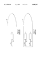
- FIGS. 6 and 7 show two known marine vessel arrangements
- FIGS. 8 and 9 show two arrangements of a single engine with a single hydrostatic motor and propeller
- FIG. 10 shows an arrangement with two engines, two hydrostatic pumps, two hydrostatic motors, and a pressurized fluid distributor
- FIG. 11 shows a single engine, two hydrostatic motors, a single hydrostatic pump, and a high pressure fluid distributor.
- FIG. 1 shows a highly simplified schematic representative of a hydrostatic marine propulsion system made in accordance with the concept of the present invention.
- a first hydrostatic pump 10 is driven by a first engine 12.
- an output shaft of the first engine 12 is connected to a shaft of the first hydrostatic pump 10 to drive it and pressurize fluid which then flows through line 14.
- a first hydrostatic motor 20 drives a first propeller shaft 24 to which a propeller 26 is attached for rotation.
- a fluid reservoir 30 provides a source of fluid that is drawn into the first hydrostatic pump 10, through line 40.
- Various sensors can be used to monitor parameters of the first engine 12. For example, the temperature of an operating fluid can be measured, as represented by dashed line 51.
- the operating speed of the first engine 12 can be measured by an appropriate sensor such as a tachometer, and a representative signal can be provided on dashed line 52.
- Another sensor such as a throttle position sensor 60, can provide information on dashed line 53 which is representative of the position of a throttle 64.
- dashed line 51 can alternatively be connected between the reservoir 30 and an engine control unit 70 to monitor the temperature of the fluid in the reservoir 30.
- air 76 is drawn into the first engine 12.
- Operation of the first engine 12 causes the first hydrostatic pump to rotate and pressurize fluid which flows through line 14 to a first valve 90.
- the first valve has a single inlet 92 connected in fluid communication with the first hydrostatic pump 10, through line 14.
- the valve 90 has a first outlet 94 that is connected to an inlet 98 of the first hydrostatic motor 20.
- a second outlet 100 of the first valve 90 is connected in fluid communication with the fluid reservoir 30, through line 104.
- the position of the valve 90 determines the ratio between the quantity of fluid flowing through line 106 to the first hydrostatic motor 20 and the quantity of fluid flowing through line 104 back to the reservoir.
- valve 90 If the valve 90 is fully opened, under the control of the engine control unit 70 through signals on dashed lines 110, all of the fluid flowing through line 14 is directed through line 104 to the reservoir and the first hydrostatic motor 20 is completely bypassed. On the other hand, if the first valve 90 is completely closed under the control of the engine control unit 70, no fluid flows through line 104 to the reservoir 30 and all of the fluid flowing through line 14 is directed through line 106 to drive the first hydrostatic motor 20.
- Fluid flowing through line 106 to drive the first hydrostatic motor 20 then returns to the reservoir 30 through line 116.
- the first hydrostatic pump 10 draws fluid from the reservoir 30, pressurizes it, and directs it through line 14 back to the valve 90 to be distributed according to the valve position determined by the engine control unit 70.
- FIG. 1 illustrates a single engine 12, a single hydrostatic pump 10, a single valve 90, and a single hydrostatic motor 20.
- the present invention has the flexibility to incorporate a plurality of engines, hydrostatic pumps, and hydrostatic motors.
- Control of the valve 90 by the engine control unit 70 can be performed in various different manners.
- One preferred control scheme is illustrated in a highly simplified schematic flow chart in FIG. 2. It should be understood that the flow chart in FIG. 2 is intended to provide a general description of the control variables and the type of actions taken by the engine control unit 70 in response to changes in magnitude of those control variables.
- the logical flow of the flow chart in FIG. 2 begins at node 200 after which the engine control unit 70 determines if a sudden movement of the throttle 64 has occurred at functional block 204. If the change in throttle position, as detected by the throttle position sensors 60 in FIG. 1, indicate that the operator of the marine vessel has changed the throttle handle position by a significant amount, the engine control unit 70 takes the steps shown in FIG. 2 beginning with functional block 210.
- the interrogation represented by functional block 204 is intended to determine if the throttle handle has been moved a significant amount, rather than merely a slight change. For example, if the operator of the marine vessel suddenly changes the control handle by moving the throttle from a near idle position to a position representing wide open throttle, or WOT, the throttle position would exceed the limit and the steps beginning with functional block 210 would be executed.
- the engine control unit 70 would first determine a desired engine speed range that has been preselected as a function of the propulsion system and the marine vessel on which it is used.
- FIG. 3 shows a hypothetical torque curve 300 and horsepower curve 302 for an exemplary marine propulsion system. As can be seen, both the torque curve 300 and the horsepower curve 302 vary as a function of engine speed.
- Functional block 210 in FIG. 2 would select an upper and lower engine speed limit, such as those represented by lines 304 and 306 in FIG. 3, and control the valve 90 in order to maintain the engine speed between those limits.
- the engine control unit 70 is intended to prevent changes in engine speed that would move the engine speed, measured in RPM's, out of the range defined by dashed lines 304 and 306. With reference to FIGS. 1, 2, and 3, if the engine speed is below the lower limit 304, the engine control unit 70 would command valve 90 to divert more fluid through line 104 to the reservoir 30 rather than through line 106 to the hydrostatic motor 20. This will allow the engine 12 to increase in speed to the range defined between dashed lines 304 and 306 in FIG. 3.
- the engine control unit 70 can increase the amount of fluid flowing through line 106 to the hydrostatic motor 20 and decrease the amount of fluid flowing through line 104 to the reservoir 30. This action will load the engine and decrease engine speed.
- the engine control unit 70 in FIG. 1 determines the error between the actual RPM and the desired RPM range as represented by functional block 212 in FIG. 2.
- a PID (proportional, integral, derivative) controller is used to calculate a desired valve position V ⁇ RPM based on the difference between actual RPM and the desired range shown in FIG. 3.
- V ⁇ RPM represents the valve position calculated only as a function of the RPM error which is calculated in functional block 212 with respect to the error between the actual RPM and the desired RPM range illustrated in FIG. 3 between the lower RPM limit 304 and upper RPM limit 306. This value is calculated by the PID control system of functional block 214. It is also used as the resultant valve position V POS as represented in functional block 216.
- the desired valve position V POS can be determined as a function of the RPM error (i.e. V ⁇ RPM ), as described above, or as a function of other variables which will be described below.
- the engine control unit 70 calculates a desired valve position V RPM as a sole function of the engine RPM. This is represented in functional block 220 of FIG. 2 and in the graphical representation of FIG. 4.
- line 400 represents the desired relationship between the valve opening, as a percentage, and the engine speed.
- a preselected engine speed e.g. 600 RPM
- dashed line 404 the valve remains completely open to bypass all of the fluid from the pump 10 through line 104 to the reservoir 30 shown in FIG. 1. This results in virtually no torque applied to the propeller shaft 24 by the hydrostatic motor 20.
- an upper limit e.g. 1500 RPM
- the valve is completely closed and all fluid from the hydrostatic pump 10 is directed by valve 90 through line 106 to the hydrostatic motor 20.
- the valve opening is determined as a function of RPM.
- the engine control unit 70 monitors the engine speed and selects an appropriate valve opening percentage as a function of engine speed. After performing this function, as represented by functional block 220 in FIG. 2, the engine control unit 70 sets the valve position V POS equal to the valve position V RPM which is determined as a sole function of engine speed, as represented in functional block 230.
- the engine control unit 70 determines whether or not the operator of the marine vessel has requested any change in throttle position. This is accomplished by the interrogation of functional block 240. It should be understood that the change in throttle position, as provided by a signal from the throttle position sensor 60 in FIG. 1, detected by functional block 240 is significantly less than the change in throttle position detected by the interrogation of functional block 204. The much larger throttle position change V TPS detected by functional block 204 represents the change from an idle speed to wide open throttle WOT or a magnitude which is a significant percentage of that full travel. However, the change detected by functional block 240 is much smaller.
- the engine control unit 70 determines whether the engine speed is above a fill power value. If it is, the valve position V ⁇ TPS is set to zero at block 246. In other words, the engine control unit 70 will allow the RPM to change solely as a function of throttle position change and will not attempt to interfere with this natural change since the propulsion system is already operating at or above the engine's full power value.
- valve position V POS is set equal to the sum of the valve position determined by functional block 220 and the valve position determined, by an appropriate transfer function, as a function of the magnitude of change in throttle position at block 240.
- the engine control unit 70 determines whether or not an over temperature condition may exist in the oil reservoir 30. This interrogation is represented by functional block 270. It should be noted that functional block 270 is performed either after functional block 216 or after functional block 250. If an over temperature exists, the valve position V POS is set to zero at functional block 272 and the duty cycle which controls the valve 90 is determined accordingly at functional block 278. If the oil temperature is not over a preselected threshold, the duty cycle for the valve 90 is set by functional block 278 in accordance with the valve position V POS determined at functional block 250. The control steps are then repeated.
- FIG. 5 represents the graphical depictions of some of the steps described above.
- the graphical representations in FIG. 5 are intended to hypothetically illustrate certain changes in parameters as the engine control unit 70 exercises the steps representing by functional blocks 204, 220, 230, 240, 244, and 250 in FIG. 2.
- line 500 represents a throttle control position during an initial period of time. The throttle control position is then suddenly changed to that represented by line 510 by the operator. This could represent a slight increase in the throttle position that would be typical if a marine vessel operator desired a slight increase in boat speed.
- the change from line 500 to line 510 is not significantly large to trigger a positive answer by the interrogation of functional block 204 in FIG. 2.
- the engine control unit 70 would select valve opening settings based on the relationship represented by line 400 in FIG. 4. This would cause the valve position to move from one position represented by line 520 to a more closed position represented by line 530. This change would be accomplished by functional blocks 220 and 230 in FIG. 2. This calculated valve position is identified as V RPM in the discussion above.
- the logic performed by functional blocks 240, 244, and 250 in FIG. 2 would result in a momentary opening of the valve 90 in order to temporarily increase the engine speed to facilitate the change in boat speed requested by the operator.
- This momentary change in valve position represented by line 550 would be added, at functional block 250 in FIG. 2, to the relationship represented by lines 520 and 530.
- the result is a relationship represented by line 560 in FIG. 5. As a result of this combined effect, the engine speed changes from the one represented by line 560 to that represented by line 570.
- the most significant advantage of a hydrostatic propulsion system is that the engine and the propeller shaft need not be directly and mechanically tied to each other.
- the engine 12 has an output shaft 600, such as its crankshaft, which is disposed on a common centerline with a propeller shaft 610 of the marine vessel 620.
- the engine 12 In a configuration such as that represented in FIG. 6, the engine 12 must be placed in line with the propeller shaft 610. This significantly limits the flexibility of the boat designer regarding the location of the engine 12.
- FIG. 7 shows a slightly different arrangement which is generally known to those skilled in the art.
- Two engines, 12 and 13 each are connected with their output shafts, 600 and 601, aligned on common axes of rotation with propeller shafts, 610 and 611, respectively.
- the requirement that the output shafts be aligned with the propeller shafts severely limits the flexibility of location of the engines, 12 and 13.
- FIG. 8 shows one possible installation in accordance with the present invention.
- the engine 12 drives a hydrostatic pump 10 which is connected in fluid communication with a hydrostatic motor 20.
- a valve 90 as described above in conjunction with FIG. 1, would be incorporated either within the housing of the hydrostatic pump 10 or within the housing of the hydrostatic motor 20. Therefore, it is not shown in FIG. 8.
- both the valve 90 and reservoir 30 described above in conjunction with FIG. 1 are enclosed within the housing of the hydrostatic pump 10. Therefore, they will not appear in the Figures relating to the following description.
- the engine 12 can be aligned perpendicularly to its required position in FIG. 6. In fact, it should further be understood that the engine 12 can be positioned anywhere within the structure of the vessel 620 that is deemed desirable by the boat designer.
- Lines 106 and 40 in FIG. 8 are typically flexible hoses which have sufficient strength to transmit the pressurized fluid from the hydrostatic pump 10 to the hydrostatic motor 20.
- FIG. 9 shows a slightly modified arrangement of the components discussed above in conjunction with FIG. 8.
- the engine 12 is moved forward in the vessel 620.
- the engine 12 can be moved to virtually any location within the structure of the vessel 620 because the hydrostatic pump 10 is connected to the hydrostatic motor 20 by flexible tubing or hoses, 40 and 106.
- FIGS. 8 and 9 it can be seen that the engine 12 is not only moved forward in FIG. 9, but also rotated by 180 degrees from its position in FIG. 8.
- FIG. 10 shows an alternative embodiment of the present invention in which two engines, 12 and 13, drive two hydrostatic pumps, 10 and 11, respectively.
- the two hydrostatic motors, 20 and 21, receive pressurized fluid through a distributor 900.
- the function of the distributor 900 is to determine the share of fluid each of the hydrostatic motors, 20 and 21, receives. This is particularly useful when the motors, 20 and 21 are also used for steering purposes. In other words, if more pressurized fluid is provided to hydrostatic motor 21 than to hydrostatic motor 20, that imbalance in torque provided by the two hydrostatic motors will cause the vessel 620 to turn.
- the two engines, 12 and 13 need not be aligned relative to each other in any particular configuration.
- engine 13 is aligned with the centerline of the vessel 620 while engine 12 is aligned perpendicularly to the centerline of the vessel.
- the pressure lines, 40 and 106 are identified by reference numeral functionally.
- the pressurized fluid is provided through line 106 and return fluid flows through line 40.
- Reference numerals 40' and 106' represent lines with similar functions, but on the opposite side of the distributor 900.
- FIG. 11 shows an embodiment of the present invention with a single engine 12 and a single hydrostatic pump 10, but two hydrostatic motors, 20 and 21, driving two propellers, 26 and 27, respectively.
- a distributor 900 distributes the pressurized oil and returning oil as desired by the vessel operator. As described above, this distribution of high pressure oil by the distributor 900 to the two hydrostatic motors, 20 and 21, can be beneficial in steering the vessel 620.
- valve 90 serves a useful purpose in allowing some of the oil from the hydrostatic pump 10 to bypass the hydrostatic motor 20 and return immediately to the reservoir 30.
- This bypassing of some high pressure oil through lines 14 and 104 effectively unloads the engine 12 to a preselected degree which is determined by the amount that valve 90 is opened for these bypassing purposes.
- the engine 12 When the engine 12 is unloaded in this manner, it increases in speed for any particular throttle position and achieves a more advantageous and efficient operating characteristic as described above in conjunction with FIG. 3. By allowing the engine 12 to operate at a more efficient engine speed, improved acceleration can be achieved.
- the engine control unit 70 can monitor the throttle position signal provided by the throttle position sensor 60, and the engine speed signal provided on dashed line 52 from a tachometer, or similar device, and a temperature signal provided on dashed line 51 which indicates oil temperature.
- the engine control unit 70 responds to at least three different conditions.
- One condition consists of a rapid and significant change in throttle position such as that which would occur if the boat operator moves a throttle control handle from idle speed to wide open throttle WOT.
- Another condition would occur when the operator makes a slight, but discernable, change in the throttle handle position which is less than the severe magnitude of change described above.
- a third condition is during normal running when the engine control unit 70 continually monitors the engine speed and adjusts the valve 90 to match its percentage opening to a predetermined relationship as discussed above in conjunction with FIG. 4.
- the valve position it is typical for the valve position to be controlled as a dual function of both engine speed and the moderate change in throttle position as described above in conjunction with FIG. 5.
- the present invention makes possible the use of hydrostatic transmissions in pleasure craft where moderately rapid acceleration are sometimes desired.
- the ability to use hydrostatic transmissions in pleasure craft provides the additional benefit of allowing extremely flexible placement of the engine, hydrostatic pump, and hydrostatic motors within the structure of the marine vessel.
Landscapes
- Chemical & Material Sciences (AREA)
- Engineering & Computer Science (AREA)
- Combustion & Propulsion (AREA)
- Mechanical Engineering (AREA)
- Ocean & Marine Engineering (AREA)
- Fluid-Pressure Circuits (AREA)
Abstract
Description
Claims (20)
Priority Applications (1)
| Application Number | Priority Date | Filing Date | Title |
|---|---|---|---|
| US09/260,346 US6099367A (en) | 1999-03-02 | 1999-03-02 | Hydrostatic propulsion system for a marine vessel |
Applications Claiming Priority (1)
| Application Number | Priority Date | Filing Date | Title |
|---|---|---|---|
| US09/260,346 US6099367A (en) | 1999-03-02 | 1999-03-02 | Hydrostatic propulsion system for a marine vessel |
Publications (1)
| Publication Number | Publication Date |
|---|---|
| US6099367A true US6099367A (en) | 2000-08-08 |
Family
ID=22988800
Family Applications (1)
| Application Number | Title | Priority Date | Filing Date |
|---|---|---|---|
| US09/260,346 Expired - Fee Related US6099367A (en) | 1999-03-02 | 1999-03-02 | Hydrostatic propulsion system for a marine vessel |
Country Status (1)
| Country | Link |
|---|---|
| US (1) | US6099367A (en) |
Cited By (15)
| Publication number | Priority date | Publication date | Assignee | Title |
|---|---|---|---|---|
| US6547610B2 (en) | 2000-09-15 | 2003-04-15 | Korea Institute Of Machinery And Materials | Parallel-operated hydraulic motor type stern propulsion apparatus for boats and hydraulic system for controlling the same |
| US6701890B1 (en) * | 2001-12-06 | 2004-03-09 | Brunswick Corporation | Method for controlling throttle air velocity during throttle position changes |
| US20050106958A1 (en) * | 2003-09-22 | 2005-05-19 | Kazuhiko Ohtsuki | Boat propulsion system |
| KR100652111B1 (en) * | 2005-06-16 | 2006-12-01 | 정의적 | Hydraulic Driven Low Speed Navigation System and Its Construction Method |
| US20070218782A1 (en) * | 2006-03-16 | 2007-09-20 | Rkl Technical Solutions, Llc | Hydra-marine propulsion system |
| US20070219047A1 (en) * | 2006-03-13 | 2007-09-20 | Kubota Corporation | Operating apparatus for hydrostatic continously variable speed-change device for work vehicle |
| US20100090821A1 (en) * | 2006-09-01 | 2010-04-15 | Gallon Mark W | Braking display apparatus |
| US8224512B1 (en) * | 2009-01-21 | 2012-07-17 | Brunswick Corporation | Backup method for controlling the operation of a marine vessel when a throttle lever is disabled |
| CN103010443A (en) * | 2012-11-27 | 2013-04-03 | 张家港市飞驰机械制造有限公司 | Hydraulic pressure system used for controlling traveling of float clearing boat |
| CN104709456A (en) * | 2015-03-24 | 2015-06-17 | 上海海洋大学 | Series-parallel hybrid power system for tuna longline boat |
| JP2016222108A (en) * | 2015-05-29 | 2016-12-28 | ヤンマー株式会社 | Marine gear device |
| CN106956762A (en) * | 2017-04-25 | 2017-07-18 | 中国海洋大学 | A kind of hydraulic hybrid propulsion plant |
| WO2018085933A1 (en) * | 2016-11-10 | 2018-05-17 | Yule Dean | Thruster apparatuses, and methods of operating same |
| IT201700015579A1 (en) * | 2017-02-13 | 2018-08-13 | As Service Srl | INTEGRATED PROPULSION SYSTEM FOR BOATS |
| CN109436264A (en) * | 2018-12-05 | 2019-03-08 | 燕山大学 | A kind of electro-hydraulic propulsion device of bionic fish tail |
Citations (18)
| Publication number | Priority date | Publication date | Assignee | Title |
|---|---|---|---|---|
| US3660975A (en) * | 1970-09-17 | 1972-05-09 | Lucas Industries Ltd | Hydrostatic transmission systems |
| US3672166A (en) * | 1970-04-08 | 1972-06-27 | Sigma | Variable ratio hydrostatic transmissions |
| US3685286A (en) * | 1970-10-22 | 1972-08-22 | Alwyne Lee | Fluid control valve |
| US4215546A (en) * | 1977-08-27 | 1980-08-05 | Kombinat Typowych Elementow Hydrauliki Silowej "Pszl-Hydral" | Hydrostatic transmission control system |
| JPS5653995A (en) * | 1979-10-09 | 1981-05-13 | Kawasaki Heavy Ind Ltd | Hydraulic driving system |
| US4273543A (en) * | 1979-10-01 | 1981-06-16 | Engine Technology, Inc. | Emergency marine propulsion using existing propeller shaft |
| US4358280A (en) * | 1977-01-07 | 1982-11-09 | Valeo | Device for rotationally driving and steering a screw-rudder of a floating vehicle |
| US4412500A (en) * | 1979-01-04 | 1983-11-01 | Schottel-Werft, Josef Becker Gmbh & Co. Kg | Drive mechanism for ships or the like comprising a main propeller and an auxiliary mechanism |
| US4871332A (en) * | 1986-05-12 | 1989-10-03 | Nautical Propulsion Research Limited | Naval propulsion plant with hydraulic transmission |
| US4901529A (en) * | 1986-07-23 | 1990-02-20 | Honda Giken Kogyo Kabushiki Kaisha | Hydraulically operated continuously variable transmission |
| US5061212A (en) * | 1989-11-21 | 1991-10-29 | Urs Morgenthaler | Ship drive with variable-pitch propeller |
| US5094077A (en) * | 1989-07-12 | 1992-03-10 | Kanzaki Kokyukoki, Mfg., Co., Ltd. | Hydrostatic transmission with interconnected swash plate neutral valve and brake unit |
| US5121603A (en) * | 1989-10-20 | 1992-06-16 | Sauer-Sundstrand Gmbh & Co. | Device for pressure-regulated variable displacement motors with rpm-dependent set pressure compensation |
| US5168703A (en) * | 1989-07-18 | 1992-12-08 | Jaromir Tobias | Continuously active pressure accumulator power transfer system |
| US5398505A (en) * | 1992-10-29 | 1995-03-21 | Aisin Seiki Kabushiki Kaisha | Fluid pressure driving system |
| US5476400A (en) * | 1994-10-12 | 1995-12-19 | Theophanides; Andy E. | Hydraulic power system for a boat |
| US5588294A (en) * | 1994-09-13 | 1996-12-31 | Kanzaki Kokyukoki Mfg. Co. Ltd. | Hydrostatic transmission |
| US5813887A (en) * | 1997-03-20 | 1998-09-29 | Mark; Theodore | Marine propulsion system |
-
1999
- 1999-03-02 US US09/260,346 patent/US6099367A/en not_active Expired - Fee Related
Patent Citations (18)
| Publication number | Priority date | Publication date | Assignee | Title |
|---|---|---|---|---|
| US3672166A (en) * | 1970-04-08 | 1972-06-27 | Sigma | Variable ratio hydrostatic transmissions |
| US3660975A (en) * | 1970-09-17 | 1972-05-09 | Lucas Industries Ltd | Hydrostatic transmission systems |
| US3685286A (en) * | 1970-10-22 | 1972-08-22 | Alwyne Lee | Fluid control valve |
| US4358280A (en) * | 1977-01-07 | 1982-11-09 | Valeo | Device for rotationally driving and steering a screw-rudder of a floating vehicle |
| US4215546A (en) * | 1977-08-27 | 1980-08-05 | Kombinat Typowych Elementow Hydrauliki Silowej "Pszl-Hydral" | Hydrostatic transmission control system |
| US4412500A (en) * | 1979-01-04 | 1983-11-01 | Schottel-Werft, Josef Becker Gmbh & Co. Kg | Drive mechanism for ships or the like comprising a main propeller and an auxiliary mechanism |
| US4273543A (en) * | 1979-10-01 | 1981-06-16 | Engine Technology, Inc. | Emergency marine propulsion using existing propeller shaft |
| JPS5653995A (en) * | 1979-10-09 | 1981-05-13 | Kawasaki Heavy Ind Ltd | Hydraulic driving system |
| US4871332A (en) * | 1986-05-12 | 1989-10-03 | Nautical Propulsion Research Limited | Naval propulsion plant with hydraulic transmission |
| US4901529A (en) * | 1986-07-23 | 1990-02-20 | Honda Giken Kogyo Kabushiki Kaisha | Hydraulically operated continuously variable transmission |
| US5094077A (en) * | 1989-07-12 | 1992-03-10 | Kanzaki Kokyukoki, Mfg., Co., Ltd. | Hydrostatic transmission with interconnected swash plate neutral valve and brake unit |
| US5168703A (en) * | 1989-07-18 | 1992-12-08 | Jaromir Tobias | Continuously active pressure accumulator power transfer system |
| US5121603A (en) * | 1989-10-20 | 1992-06-16 | Sauer-Sundstrand Gmbh & Co. | Device for pressure-regulated variable displacement motors with rpm-dependent set pressure compensation |
| US5061212A (en) * | 1989-11-21 | 1991-10-29 | Urs Morgenthaler | Ship drive with variable-pitch propeller |
| US5398505A (en) * | 1992-10-29 | 1995-03-21 | Aisin Seiki Kabushiki Kaisha | Fluid pressure driving system |
| US5588294A (en) * | 1994-09-13 | 1996-12-31 | Kanzaki Kokyukoki Mfg. Co. Ltd. | Hydrostatic transmission |
| US5476400A (en) * | 1994-10-12 | 1995-12-19 | Theophanides; Andy E. | Hydraulic power system for a boat |
| US5813887A (en) * | 1997-03-20 | 1998-09-29 | Mark; Theodore | Marine propulsion system |
Cited By (25)
| Publication number | Priority date | Publication date | Assignee | Title |
|---|---|---|---|---|
| US6547610B2 (en) | 2000-09-15 | 2003-04-15 | Korea Institute Of Machinery And Materials | Parallel-operated hydraulic motor type stern propulsion apparatus for boats and hydraulic system for controlling the same |
| US6701890B1 (en) * | 2001-12-06 | 2004-03-09 | Brunswick Corporation | Method for controlling throttle air velocity during throttle position changes |
| US20050106958A1 (en) * | 2003-09-22 | 2005-05-19 | Kazuhiko Ohtsuki | Boat propulsion system |
| US6988917B2 (en) * | 2003-09-22 | 2006-01-24 | Kazuhiko Ohtsuki | Boat propulsion system |
| US20060035542A1 (en) * | 2003-09-22 | 2006-02-16 | Kazuhiko Ohtsuki | Boat propulsion system |
| US7168997B2 (en) * | 2003-09-22 | 2007-01-30 | Kazuhiko Ohtsuki | Boat propulsion system |
| KR100652111B1 (en) * | 2005-06-16 | 2006-12-01 | 정의적 | Hydraulic Driven Low Speed Navigation System and Its Construction Method |
| US7854182B2 (en) * | 2006-03-13 | 2010-12-21 | Kubota Corporation | Operating apparatus for hydrostatic continuously variable speed-change device for work vehicle |
| US20070219047A1 (en) * | 2006-03-13 | 2007-09-20 | Kubota Corporation | Operating apparatus for hydrostatic continously variable speed-change device for work vehicle |
| WO2007108864A2 (en) * | 2006-03-16 | 2007-09-27 | Rkl Technical Solutions, Llc | Hydra-marine propulsion system |
| WO2007108864A3 (en) * | 2006-03-16 | 2008-08-14 | Rkl Technical Solutions Llc | Hydra-marine propulsion system |
| US20070218782A1 (en) * | 2006-03-16 | 2007-09-20 | Rkl Technical Solutions, Llc | Hydra-marine propulsion system |
| US20100090821A1 (en) * | 2006-09-01 | 2010-04-15 | Gallon Mark W | Braking display apparatus |
| US8525661B2 (en) * | 2006-09-01 | 2013-09-03 | Mark W. Gallon | Water vehicle braking display apparatus |
| US8224512B1 (en) * | 2009-01-21 | 2012-07-17 | Brunswick Corporation | Backup method for controlling the operation of a marine vessel when a throttle lever is disabled |
| CN103010443B (en) * | 2012-11-27 | 2016-02-24 | 苏州飞驰环保科技股份有限公司 | For controlling to float clearly the hydraulic system that shipping agency enters |
| CN103010443A (en) * | 2012-11-27 | 2013-04-03 | 张家港市飞驰机械制造有限公司 | Hydraulic pressure system used for controlling traveling of float clearing boat |
| CN104709456A (en) * | 2015-03-24 | 2015-06-17 | 上海海洋大学 | Series-parallel hybrid power system for tuna longline boat |
| JP2016222108A (en) * | 2015-05-29 | 2016-12-28 | ヤンマー株式会社 | Marine gear device |
| WO2018085933A1 (en) * | 2016-11-10 | 2018-05-17 | Yule Dean | Thruster apparatuses, and methods of operating same |
| US11220319B2 (en) | 2016-11-10 | 2022-01-11 | Kobelt Manufacturing Co. Ltd. | Thruster apparatuses, and methods of operating same |
| IT201700015579A1 (en) * | 2017-02-13 | 2018-08-13 | As Service Srl | INTEGRATED PROPULSION SYSTEM FOR BOATS |
| CN106956762A (en) * | 2017-04-25 | 2017-07-18 | 中国海洋大学 | A kind of hydraulic hybrid propulsion plant |
| CN109436264A (en) * | 2018-12-05 | 2019-03-08 | 燕山大学 | A kind of electro-hydraulic propulsion device of bionic fish tail |
| CN109436264B (en) * | 2018-12-05 | 2023-08-01 | 燕山大学 | A bionic fishtail electro-hydraulic propulsion device |
Similar Documents
| Publication | Publication Date | Title |
|---|---|---|
| US6099367A (en) | Hydrostatic propulsion system for a marine vessel | |
| CA2978824C (en) | Wakeboat engine powered ballasting apparatus and methods | |
| US6938719B2 (en) | Speed control system for wheeled hydraulic traveling vehicle | |
| EP2581271B1 (en) | Vehicle auxiliary hydraulic system | |
| KR100932713B1 (en) | Adjustable Power Transmission Clutch and Marine Transmission | |
| US2833362A (en) | Hydraulically driven motor vehicle | |
| US7131386B1 (en) | Marine propulsion system with pressure compensated hydraulic supply capability | |
| US4596118A (en) | Hydrostatic self-regulating drive system | |
| CA1047360A (en) | Winch control | |
| US6338247B1 (en) | System for controlling a hydraulic vehicle drive | |
| US4887984A (en) | Marine transmission with fluid coupler | |
| US5186612A (en) | Variable pressure inlet system for hydraulic pumps | |
| US20070227802A1 (en) | Hybrid earthmover | |
| US3633359A (en) | Hydraulic apparatus | |
| CA1055806A (en) | Engine and transmission control system | |
| GB1131456A (en) | Hydrostatic transmission | |
| US5687808A (en) | Four wheel drive mechanism | |
| CA1049889A (en) | Hydrostatic transmission | |
| US3302390A (en) | Transmission | |
| US5879207A (en) | Single engine dual propeller water craft | |
| JP2018203145A (en) | Reduction reverse gear | |
| US4462210A (en) | Input torque control for a variable displacement hydraulic transmission | |
| CA2525397C (en) | Outboard motor hydraulic mechanism | |
| US4329845A (en) | Augmented charging system for a hydrostatic transmission | |
| GB2222664A (en) | Hydraulic transmission with braking |
Legal Events
| Date | Code | Title | Description |
|---|---|---|---|
| AS | Assignment |
Owner name: BRUNSWICK CORPORATION, ILLINOIS Free format text: ASSIGNMENT OF ASSIGNORS INTEREST;ASSIGNORS:WHITE, BRIAN R.;NOTARESCHI, VINCE E.;HINES, GRANT W.;REEL/FRAME:009810/0067;SIGNING DATES FROM 19990204 TO 19990216 |
|
| FPAY | Fee payment |
Year of fee payment: 4 |
|
| FPAY | Fee payment |
Year of fee payment: 8 |
|
| AS | Assignment |
Owner name: JPMORGAN CHASE BANK, N.A., TEXAS Free format text: SECURITY AGREEMENT;ASSIGNORS:BRUNSWICK CORPORATION;TRITON BOAT COMPANY, L.P.;ATTWOOD CORPORATION;AND OTHERS;REEL/FRAME:022092/0365 Effective date: 20081219 Owner name: JPMORGAN CHASE BANK, N.A.,TEXAS Free format text: SECURITY AGREEMENT;ASSIGNORS:BRUNSWICK CORPORATION;TRITON BOAT COMPANY, L.P.;ATTWOOD CORPORATION;AND OTHERS;REEL/FRAME:022092/0365 Effective date: 20081219 |
|
| AS | Assignment |
Owner name: THE BANK OF NEW YORK MELLON TRUST COMPANY, N.A., I Free format text: SECURITY AGREEMENT;ASSIGNORS:BRUNSWICK CORPORATION;ATTWOOD CORPORATION;BOSTON WHALER, INC.;AND OTHERS;REEL/FRAME:023180/0493 Effective date: 20090814 Owner name: THE BANK OF NEW YORK MELLON TRUST COMPANY, N.A.,IL Free format text: SECURITY AGREEMENT;ASSIGNORS:BRUNSWICK CORPORATION;ATTWOOD CORPORATION;BOSTON WHALER, INC.;AND OTHERS;REEL/FRAME:023180/0493 Effective date: 20090814 |
|
| AS | Assignment |
Owner name: LAND 'N' SEA DISTRIBUTING, INC., FLORIDA Free format text: RELEASE BY SECURED PARTY;ASSIGNOR:JPMORGAN CHASE BANK, N.A., AS ADMINISTRATIVE AGENT;REEL/FRAME:026026/0001 Effective date: 20110321 Owner name: BRUNSWICK FAMILY BOAT CO. INC., WASHINGTON Free format text: RELEASE BY SECURED PARTY;ASSIGNOR:JPMORGAN CHASE BANK, N.A., AS ADMINISTRATIVE AGENT;REEL/FRAME:026026/0001 Effective date: 20110321 Owner name: BRUNSWICK CORPORATION, ILLINOIS Free format text: RELEASE BY SECURED PARTY;ASSIGNOR:JPMORGAN CHASE BANK, N.A., AS ADMINISTRATIVE AGENT;REEL/FRAME:026026/0001 Effective date: 20110321 Owner name: BRUNSWICK COMMERICAL & GOVERNMENT PRODUCTS, INC., Free format text: RELEASE BY SECURED PARTY;ASSIGNOR:JPMORGAN CHASE BANK, N.A., AS ADMINISTRATIVE AGENT;REEL/FRAME:026026/0001 Effective date: 20110321 Owner name: BOSTON WHALER, INC., FLORIDA Free format text: RELEASE BY SECURED PARTY;ASSIGNOR:JPMORGAN CHASE BANK, N.A., AS ADMINISTRATIVE AGENT;REEL/FRAME:026026/0001 Effective date: 20110321 Owner name: BRUNSWICK LEISURE BOAT COMPANY, LLC, INDIANA Free format text: RELEASE BY SECURED PARTY;ASSIGNOR:JPMORGAN CHASE BANK, N.A., AS ADMINISTRATIVE AGENT;REEL/FRAME:026026/0001 Effective date: 20110321 Owner name: BRUNSWICK BOWLING & BILLIARDS CORPORATION, ILLINOI Free format text: RELEASE BY SECURED PARTY;ASSIGNOR:JPMORGAN CHASE BANK, N.A., AS ADMINISTRATIVE AGENT;REEL/FRAME:026026/0001 Effective date: 20110321 Owner name: TRITON BOAT COMPANY, L.P., TENNESSEE Free format text: RELEASE BY SECURED PARTY;ASSIGNOR:JPMORGAN CHASE BANK, N.A., AS ADMINISTRATIVE AGENT;REEL/FRAME:026026/0001 Effective date: 20110321 Owner name: ATTWOOD CORPORATION, MICHIGAN Free format text: RELEASE BY SECURED PARTY;ASSIGNOR:JPMORGAN CHASE BANK, N.A., AS ADMINISTRATIVE AGENT;REEL/FRAME:026026/0001 Effective date: 20110321 Owner name: LUND BOAT COMPANY, MINNESOTA Free format text: RELEASE BY SECURED PARTY;ASSIGNOR:JPMORGAN CHASE BANK, N.A., AS ADMINISTRATIVE AGENT;REEL/FRAME:026026/0001 Effective date: 20110321 |
|
| AS | Assignment |
Owner name: JPMORGAN CHASE BANK, N.A., AS ADMINISTRATIVE AGENT Free format text: SECURITY AGREEMENT;ASSIGNORS:BRUNSWICK CORPORATION;ATTWOOD CORPORATION;BOSTON WHALER, INC.;AND OTHERS;REEL/FRAME:026072/0239 Effective date: 20110321 |
|
| REMI | Maintenance fee reminder mailed | ||
| LAPS | Lapse for failure to pay maintenance fees | ||
| LAPS | Lapse for failure to pay maintenance fees |
Free format text: PATENT EXPIRED FOR FAILURE TO PAY MAINTENANCE FEES (ORIGINAL EVENT CODE: EXP.); ENTITY STATUS OF PATENT OWNER: LARGE ENTITY |
|
| STCH | Information on status: patent discontinuation |
Free format text: PATENT EXPIRED DUE TO NONPAYMENT OF MAINTENANCE FEES UNDER 37 CFR 1.362 |
|
| FP | Lapsed due to failure to pay maintenance fee |
Effective date: 20120808 |
|
| AS | Assignment |
Owner name: BRUNSWICK CORPORATION, ILLINOIS Free format text: RELEASE BY SECURED PARTY;ASSIGNOR:THE BANK OF NEW YORK MELLON;REEL/FRAME:031973/0242 Effective date: 20130717 |
|
| AS | Assignment |
Owner name: LAND 'N' SEA DISTRIBUTING, INC., ILLINOIS Free format text: RELEASE BY SECURED PARTY;ASSIGNOR:JPMORGAN CHASE BANK, N.A.;REEL/FRAME:034794/0300 Effective date: 20141226 Owner name: BRUNSWICK COMMERCIAL & GOVERNMENT PRODUCTS, INC., Free format text: RELEASE BY SECURED PARTY;ASSIGNOR:JPMORGAN CHASE BANK, N.A.;REEL/FRAME:034794/0300 Effective date: 20141226 Owner name: BOSTON WHALER, INC., ILLINOIS Free format text: RELEASE BY SECURED PARTY;ASSIGNOR:JPMORGAN CHASE BANK, N.A.;REEL/FRAME:034794/0300 Effective date: 20141226 Owner name: ATTWOOD CORPORATION, ILLINOIS Free format text: RELEASE BY SECURED PARTY;ASSIGNOR:JPMORGAN CHASE BANK, N.A.;REEL/FRAME:034794/0300 Effective date: 20141226 Owner name: BRUNSWICK BOWLING & BILLIARDS CORPORATION, ILLINOI Free format text: RELEASE BY SECURED PARTY;ASSIGNOR:JPMORGAN CHASE BANK, N.A.;REEL/FRAME:034794/0300 Effective date: 20141226 Owner name: BRUNSWICK CORPORATION, ILLINOIS Free format text: RELEASE BY SECURED PARTY;ASSIGNOR:JPMORGAN CHASE BANK, N.A.;REEL/FRAME:034794/0300 Effective date: 20141226 Owner name: BRUNSWICK FAMILY BOAT CO. INC., ILLINOIS Free format text: RELEASE BY SECURED PARTY;ASSIGNOR:JPMORGAN CHASE BANK, N.A.;REEL/FRAME:034794/0300 Effective date: 20141226 Owner name: LUND BOAT COMPANY, ILLINOIS Free format text: RELEASE BY SECURED PARTY;ASSIGNOR:JPMORGAN CHASE BANK, N.A.;REEL/FRAME:034794/0300 Effective date: 20141226 Owner name: BRUNSWICK LEISURE BOAT COMPANY, LLC, ILLINOIS Free format text: RELEASE BY SECURED PARTY;ASSIGNOR:JPMORGAN CHASE BANK, N.A.;REEL/FRAME:034794/0300 Effective date: 20141226 |