US6070742A - Multi-segment, nesting, low profile cable management arm - Google Patents
Multi-segment, nesting, low profile cable management arm Download PDFInfo
- Publication number
- US6070742A US6070742A US09/181,289 US18128998A US6070742A US 6070742 A US6070742 A US 6070742A US 18128998 A US18128998 A US 18128998A US 6070742 A US6070742 A US 6070742A
- Authority
- US
- United States
- Prior art keywords
- segment
- cable
- segments
- recited
- attachment plate
- Prior art date
- Legal status (The legal status is an assumption and is not a legal conclusion. Google has not performed a legal analysis and makes no representation as to the accuracy of the status listed.)
- Expired - Lifetime
Links
Images


Classifications
-
- H—ELECTRICITY
- H05—ELECTRIC TECHNIQUES NOT OTHERWISE PROVIDED FOR
- H05K—PRINTED CIRCUITS; CASINGS OR CONSTRUCTIONAL DETAILS OF ELECTRIC APPARATUS; MANUFACTURE OF ASSEMBLAGES OF ELECTRICAL COMPONENTS
- H05K7/00—Constructional details common to different types of electric apparatus
- H05K7/14—Mounting supporting structure in casing or on frame or rack
- H05K7/1485—Servers; Data center rooms, e.g. 19-inch computer racks
- H05K7/1488—Cabinets therefor, e.g. chassis or racks or mechanical interfaces between blades and support structures
- H05K7/1491—Cabinets therefor, e.g. chassis or racks or mechanical interfaces between blades and support structures having cable management arrangements
Definitions
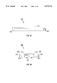
- FIG. 5 perspective of the cable managment arm extended in a forwardly extended component access position with cables attached to the cable managment arm.
- FIG. 13 is a perspective of the cable management arm being folded into an attached component.
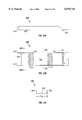
- Bolt/nut combinations 640 and 650 pivotally connect second segment 220 to third segment 230.
- the side edges of upper and lower channels 360 and 365 extend slightly farther than the floor of the respective receiving channel toward third segment 230 with an aperture formed in the side edges to insert bolt/nut combinations 640 and 650.
- the third cable tray upper side 380 and third cable tray lower side 385 extend toward second segment 220 with apertures in each tray side (380 and 385) to insert bold/nut combinations 640 and 650 and provide a pivotal attachment between second segment 220 and third segment 230.
Landscapes
- Engineering & Computer Science (AREA)
- Computer Hardware Design (AREA)
- General Engineering & Computer Science (AREA)
- Microelectronics & Electronic Packaging (AREA)
- Details Of Indoor Wiring (AREA)
Abstract
Description
Claims (27)
Priority Applications (1)
| Application Number | Priority Date | Filing Date | Title |
|---|---|---|---|
| US09/181,289 US6070742A (en) | 1998-10-28 | 1998-10-28 | Multi-segment, nesting, low profile cable management arm |
Applications Claiming Priority (1)
| Application Number | Priority Date | Filing Date | Title |
|---|---|---|---|
| US09/181,289 US6070742A (en) | 1998-10-28 | 1998-10-28 | Multi-segment, nesting, low profile cable management arm |
Publications (1)
| Publication Number | Publication Date |
|---|---|
| US6070742A true US6070742A (en) | 2000-06-06 |
Family
ID=22663647
Family Applications (1)
| Application Number | Title | Priority Date | Filing Date |
|---|---|---|---|
| US09/181,289 Expired - Lifetime US6070742A (en) | 1998-10-28 | 1998-10-28 | Multi-segment, nesting, low profile cable management arm |
Country Status (1)
| Country | Link |
|---|---|
| US (1) | US6070742A (en) |
Cited By (110)
| Publication number | Priority date | Publication date | Assignee | Title |
|---|---|---|---|---|
| US6303864B1 (en) * | 1999-12-22 | 2001-10-16 | Dell Products, L.P. | Connector arrangement and connecting method for cable management arms |
| US6305556B1 (en) * | 2000-10-26 | 2001-10-23 | Hewlett-Packard Company | Cable management solution for rack-mounted computers |
| US20010037985A1 (en) * | 1998-07-31 | 2001-11-08 | George Jordan | Computer component rack mounting arrangement |
| US6315249B1 (en) * | 1999-12-29 | 2001-11-13 | Dell Usa, L.P. | System for managing cables for a rack-mounted computer system |
| US6392149B1 (en) * | 2001-09-13 | 2002-05-21 | Sun Microsystems, Inc. | Apparatus and method for routing cables |
| US6407933B1 (en) * | 2000-10-18 | 2002-06-18 | Compaq Computer Corporation | Cable management system for use with rack mounted devices |
| US6422399B1 (en) | 2000-11-21 | 2002-07-23 | Dell Products L.P. | Rack system and method having tool-less releasable arm assembly |
| US6435354B1 (en) * | 2000-08-07 | 2002-08-20 | Dell Products L.P. | Cable management arm assembly |
| US6501020B2 (en) * | 2001-01-15 | 2002-12-31 | Chatsworth Products, Inc. | Electrical equipment and cable support assembly |
| US20030052580A1 (en) * | 2001-09-19 | 2003-03-20 | Dobler Karl J. | Snap-on slide and rail assembly and method of assembling same |
| US6554142B2 (en) | 2001-07-27 | 2003-04-29 | Dell Products L.P. | Variable mount rack system arm assembly |
| US6600665B2 (en) * | 2001-08-03 | 2003-07-29 | Hewlett-Packard Development Company, L.P. | Cable management arm with trough and breakaway feature |
| US20030222034A1 (en) * | 2002-05-31 | 2003-12-04 | International Business Machines Corporation | Electrical equipment rack and cable management arm assembly |
| US20030226812A1 (en) * | 2002-06-10 | 2003-12-11 | Wrycraft Sean Conor | Cable management system |
| US20030227753A1 (en) * | 2002-06-10 | 2003-12-11 | Wrycraft Sean Conor | Cable management system |
| US6675720B2 (en) * | 2001-08-31 | 2004-01-13 | Hewlett-Packard Development Company, L.P. | Management system for multiple cables |
| US6685033B1 (en) * | 2000-03-03 | 2004-02-03 | Dell Products L.P. | System and apparatus enabling top, front and rear access to a rack mounted computer device |
| GB2392081A (en) * | 2002-08-19 | 2004-02-25 | King Slide Works Co Ltd | Adjustable cable management arm for furniture |
| US20040035995A1 (en) * | 2002-08-20 | 2004-02-26 | King Slide Works Co., Ltd. | Adjustable cable management arm for furniture |
| GB2392608A (en) * | 2002-09-03 | 2004-03-10 | King Slide Works Co Ltd | Adjustable bracket device of a cable management arm for furniture |
| US20040108289A1 (en) * | 2002-12-06 | 2004-06-10 | King Slide Works Co., Ltd. | Detachable device of a cable management arm for furniture |
| US20040120123A1 (en) * | 2002-12-20 | 2004-06-24 | Mayer David W. | Multi-configurable telecommunications rack mounting system and method incorporating same |
| US6769551B2 (en) | 2002-07-26 | 2004-08-03 | Dell Products L.P. | System and method for utilizing non-dedicated rack space |
| US6772887B2 (en) * | 2000-12-19 | 2004-08-10 | The Siemon Company | Rack mountable fiber splice and patch enclosure |
| US20040159618A1 (en) * | 2003-02-19 | 2004-08-19 | Nguyen Minh H. | Removable rails for use on racks |
| US20040164208A1 (en) * | 2003-02-21 | 2004-08-26 | Nielson Erik R. | Method and apparatus for supporting cables |
| US20040182798A1 (en) * | 2003-03-21 | 2004-09-23 | Dell Products L.P. | Tool-less cable management attachment bracket and method of use |
| US20040216911A1 (en) * | 2003-05-01 | 2004-11-04 | Franz John P. | Drop down cable arm |
| US20040217073A1 (en) * | 2003-05-01 | 2004-11-04 | Dobler Karl J. | System and method for utilizing a tool-less rail in a rack |
| US20050006324A1 (en) * | 2003-07-09 | 2005-01-13 | Richards Nancy J. | Hinged swing bracket assembly for a rack system |
| US6866154B2 (en) | 2002-12-03 | 2005-03-15 | Dell Products L.P. | Tool-less attachment bracket |
| US20050067358A1 (en) * | 2003-09-30 | 2005-03-31 | Dell Products L.P. | Cable management flip tray assembly |
| US6902069B2 (en) | 2002-10-23 | 2005-06-07 | Dell Products L.P. | System and method for rack cable management |
| US6962397B2 (en) | 2001-09-19 | 2005-11-08 | Hewlett-Packard Development Company, L.P. | Expandable slide and rail assembly for a rack |
| US6972949B1 (en) * | 2003-12-03 | 2005-12-06 | Unisys Corporation | Cable routing system |
| US7009112B1 (en) | 2004-09-28 | 2006-03-07 | Lockheed Martin Corporation | Cable organization apparatuses and systems |
| US20060081735A1 (en) * | 2004-10-15 | 2006-04-20 | Ken-Ching Chen | Cable management arm |
| US20060081736A1 (en) * | 2004-10-15 | 2006-04-20 | Ken-Ching Chen | Support slide for cable management arm |
| US20060113433A1 (en) * | 2004-10-15 | 2006-06-01 | Ken-Ching Chen | Cable management arm assembly |
| US20060289193A1 (en) * | 2005-06-28 | 2006-12-28 | International Business Machines Corporation | Cable management system |
| US20070017883A1 (en) * | 2005-07-19 | 2007-01-25 | International Business Machines Corporation | Cable management system with adjustable length arm |
| US20070034747A1 (en) * | 2005-06-30 | 2007-02-15 | The Boeing Company | Translating conduit apparatus for an airplane or equipment |
| US20070039902A1 (en) * | 2005-08-16 | 2007-02-22 | Dell Products L.P. | Method and apparatus for securing a cable management system |
| US20070045479A1 (en) * | 2005-03-18 | 2007-03-01 | Bao Nguyen | Rugged cable management system |
| US20070076403A1 (en) * | 2005-08-16 | 2007-04-05 | Dell Products L.P. | Method and apparatus for cable management |
| US7258583B1 (en) | 2005-01-31 | 2007-08-21 | Central Industrial Supply Company | Cable management arm having cable retention members |
| US20070233781A1 (en) * | 2006-03-31 | 2007-10-04 | Spectra Logic Corporation | High density array system having multiple storage units with active movable media drawers |
| US20070230110A1 (en) * | 2006-03-31 | 2007-10-04 | Spectra Logic Corporation | High density array system with active storage media support structures |
| US20070227756A1 (en) * | 2006-03-29 | 2007-10-04 | Doerr Alan B | Reversible cable support arm |
| US20070230109A1 (en) * | 2006-03-31 | 2007-10-04 | Spectra Logic Corporation | High density array system with active storage blades |
| US20070267211A1 (en) * | 2006-05-19 | 2007-11-22 | Yazaki Corporation | Harness wiring structure |
| US20080002362A1 (en) * | 2005-03-28 | 2008-01-03 | Fujitsu Limited | Electronic apparatus |
| US7317623B2 (en) * | 2002-12-20 | 2008-01-08 | Hewlett-Packard Development Company, L.P. | Swappable mount for cable support and system and method incorporating same |
| US20080135503A1 (en) * | 2006-12-08 | 2008-06-12 | Fujitsu Limited | Electronic apparatus and in-rack electronic apparatus |
| US20080164789A1 (en) * | 2003-03-21 | 2008-07-10 | Dell Products L.P. | Tool-less Cable Management Attachment Bracket And Method Of Use |
| US20080192442A1 (en) * | 2007-02-13 | 2008-08-14 | Lupton Michael B | Dual Hinge Bracket |
| US20080259584A1 (en) * | 2007-04-18 | 2008-10-23 | Ostrowski Frankie K | Support and extension rail assembly |
| US20080259534A1 (en) * | 2007-04-18 | 2008-10-23 | Connor Lawrence T | Cassette matrix for an electrical switching apparatus |
| US20090084910A1 (en) * | 2007-09-28 | 2009-04-02 | White Thomas C | Adjustable cable tray joint |
| US7588216B1 (en) * | 2001-03-19 | 2009-09-15 | Cisco Technology, Inc. | Fiber optic cabling management using hook and loop fabric |
| US20090242233A1 (en) * | 2008-03-28 | 2009-10-01 | Fujitsu Limited | Cable management apparatus and method for managing cables of an electronic apparatus |
| US20100140422A1 (en) * | 2004-03-22 | 2010-06-10 | Panduit Corp. | Vertical Cable Manager |
| GB2466535A (en) * | 2008-12-23 | 2010-06-30 | Nexsan Technologies Ltd | Cable management for data storage devices in sliding storage means |
| US20100172087A1 (en) * | 2008-12-23 | 2010-07-08 | Nexsan Technologies Limited | Data Storage Apparatus |
| US20100181440A1 (en) * | 2009-01-21 | 2010-07-22 | Ortronics, Inc. | Articulated Cable Management Systems and Methods For Use Thereof |
| US20100258350A1 (en) * | 2008-09-25 | 2010-10-14 | Xyratex Technology Limited | Apparatus comprising rack, component, cable and cable management assembly |
| WO2010126461A1 (en) * | 2009-04-28 | 2010-11-04 | Hewlett-Packard Development Company, L.P. | Dual-arm cable-management system |
| US20110007464A1 (en) * | 2008-02-29 | 2011-01-13 | Leigh Kevin B | Modular system and retractable assembly for electronic devices |
| US20110107359A1 (en) * | 2009-10-29 | 2011-05-05 | Kah Soon Lee | Apparatus and methods for managing connection cables of portable optical drives |
| US7952023B2 (en) | 2005-09-08 | 2011-05-31 | Panduit Corp. | Wall mounted enclosure with rotating patch panel frame |
| US20110141874A1 (en) * | 2006-03-31 | 2011-06-16 | Spectra Logic Corporation | High density array system with active movable media drawers |
| US20110253647A1 (en) * | 2010-04-16 | 2011-10-20 | Hon Hai Precision Industry Co., Ltd. | Rack apparatus and cable management structure thereof |
| US20110290955A1 (en) * | 2010-05-31 | 2011-12-01 | Hon Hai Precision Industry Co., Ltd. | Cable management apparatus |
| US20120050981A1 (en) * | 2010-08-25 | 2012-03-01 | Inventec Corporation | Rack server |
| US20120170227A1 (en) * | 2011-01-05 | 2012-07-05 | The Boeing Company | Translating Equipment Rack System |
| CN102573373A (en) * | 2010-12-31 | 2012-07-11 | 鸿富锦精密工业(深圳)有限公司 | Electronic equipment |
| US20120188725A1 (en) * | 2011-01-24 | 2012-07-26 | Kabushiki Kaisha Yaskawa Denki | Electrical instrument |
| US20120292267A1 (en) * | 2011-05-17 | 2012-11-22 | Mellanox Technologies Ltd. | Mounting rail with internal power cable |
| US20130092802A1 (en) * | 2011-10-13 | 2013-04-18 | Andrew J. Doberstein | Line Extender/Retractor |
| CN103472901A (en) * | 2013-09-22 | 2013-12-25 | 杭州华为数字技术有限公司 | Pitch point and shell |
| US20140144858A1 (en) * | 2011-08-24 | 2014-05-29 | Fujitsu Limited | Casing mounting rail, blank plate, and rack mount system |
| US20140262487A1 (en) * | 2013-03-13 | 2014-09-18 | Go!Foton Holdings, Inc. | Patch panel assembly |
| US20140354131A1 (en) * | 2013-05-29 | 2014-12-04 | Go!Foton Holdings, Inc. | Patch panel cable retention mechanisms |
| WO2015034533A1 (en) * | 2013-09-09 | 2015-03-12 | Schneider Electric It Corporation | A building management rack system |
| US9173312B1 (en) * | 2014-04-30 | 2015-10-27 | Quanta Computer Inc. | Cable storage under a drawer |
| US20160186895A1 (en) * | 2014-12-30 | 2016-06-30 | King Slide Works Co., Ltd. | Cable management arm |
| US9462356B2 (en) | 2013-05-29 | 2016-10-04 | Go!Foton Holdings, Inc. | Patch panel assembly |
| WO2016170549A3 (en) * | 2015-04-23 | 2017-01-05 | Te Connectivity India Private Limited | Changeable cable manager |
| US9578779B2 (en) * | 2015-04-16 | 2017-02-21 | Sandisk Technologies Llc | Front rack cable management system and apparatus |
| US9581781B2 (en) | 2013-06-24 | 2017-02-28 | Go!Foton Holdings, Inc. | Patch panel pivoting tray cable retention mechanisms |
| US20170105302A1 (en) * | 2015-10-09 | 2017-04-13 | Sharp Kabushiki Kaisha | Support member connection mechanism and electrical apparatus including the same |
| US20170118863A1 (en) * | 2015-10-26 | 2017-04-27 | Nec Platforms Ltd. | Device, cable guide device, and cable holding member |
| US9668372B2 (en) | 2015-05-05 | 2017-05-30 | King Slide Works Co., Ltd. | Cable management device |
| US9698577B2 (en) | 2015-05-07 | 2017-07-04 | Sandisk Technologies Llc | Portable power supply unit with bus bar adapter and tool-less connection |
| CN106954362A (en) * | 2017-04-24 | 2017-07-14 | 湖北三江航天万峰科技发展有限公司 | A kind of rack cable management device |
| US20170250509A1 (en) * | 2016-02-29 | 2017-08-31 | Masterbrand Cabinets, Inc. | Compact drawer outlet |
| US9799991B2 (en) | 2015-09-14 | 2017-10-24 | Sandisk Technologies Llc | Power cord retainer |
| US20180063986A1 (en) * | 2016-08-31 | 2018-03-01 | King Slide Works Co., Ltd. | Slide rail assembly and cable management device thereof |
| US9949400B2 (en) | 2015-04-16 | 2018-04-17 | Sandisk Technologies Llc | Front rack cable management system and apparatus |
| US10054993B2 (en) | 2016-10-05 | 2018-08-21 | Sandisk Enterprise Ip Llc | Airflow guide assembly and enclosure |
| US10128642B2 (en) | 2016-06-08 | 2018-11-13 | Thomas & Betts International Llc | Foldable cable tray |
| US10190658B2 (en) | 2015-04-24 | 2019-01-29 | Hewlett Packard Enterprise Development Lp | Cable track |
| TWI649512B (en) * | 2018-02-07 | 2019-02-01 | 川湖科技股份有限公司 | Connecting device |
| EP3329570A4 (en) * | 2015-07-30 | 2019-02-27 | Sanmina Corporation | Cable management assembly for rack mounted equipment |
| US10291969B2 (en) | 2017-02-14 | 2019-05-14 | Go!Foton Holdings, Inc. | Rear cable management |
| US20200249727A1 (en) * | 2019-02-04 | 2020-08-06 | Ralph Belfiglio | Low Profile Auxiliary Component Mounting Article |
| US11112057B2 (en) | 2019-07-10 | 2021-09-07 | Ergotron, Inc. | Display mounting system and method |
| US20220232725A1 (en) * | 2021-01-21 | 2022-07-21 | Dell Products L.P. | Mechanisms and methods for two-sided rack access |
| USD999742S1 (en) | 2021-04-01 | 2023-09-26 | JTech Solutions, Inc. | Safety interlock outlet box |
| US12055762B2 (en) | 2020-07-02 | 2024-08-06 | Go!Foton Holdings, Inc. | Intelligent optical switch |
Citations (8)
| Publication number | Priority date | Publication date | Assignee | Title |
|---|---|---|---|---|
| US5018052A (en) * | 1990-01-08 | 1991-05-21 | Sun Microsystems, Inc. | Cable management apparatus for a computer workstation housing |
| US5149277A (en) * | 1988-07-18 | 1992-09-22 | Lemaster Dolan M | Connectivity management system |
| US5216579A (en) * | 1992-01-29 | 1993-06-01 | International Business Machines Corporation | Rack based packaging system for computers with cable, cooling and power management module |
| US5460441A (en) * | 1994-11-01 | 1995-10-24 | Compaq Computer Corporation | Rack-mounted computer apparatus |
| US5571256A (en) * | 1994-10-25 | 1996-11-05 | Compaq Computer Corporation | Server drawer slide mount apparatus for a rack-mounted computer system |
| US5655738A (en) * | 1995-06-07 | 1997-08-12 | Ragsdale; Thomas Ray | Cable management device |
| US5726866A (en) * | 1996-02-14 | 1998-03-10 | Compaq Computer Corporation | Slide out readily accessible chassis having a trough for protecting cables and a hinge that includes a conduit |
| US5890602A (en) * | 1997-06-27 | 1999-04-06 | Dell Usa, L.P. | Demonstrative packaging for rack mount hardware |
-
1998
- 1998-10-28 US US09/181,289 patent/US6070742A/en not_active Expired - Lifetime
Patent Citations (8)
| Publication number | Priority date | Publication date | Assignee | Title |
|---|---|---|---|---|
| US5149277A (en) * | 1988-07-18 | 1992-09-22 | Lemaster Dolan M | Connectivity management system |
| US5018052A (en) * | 1990-01-08 | 1991-05-21 | Sun Microsystems, Inc. | Cable management apparatus for a computer workstation housing |
| US5216579A (en) * | 1992-01-29 | 1993-06-01 | International Business Machines Corporation | Rack based packaging system for computers with cable, cooling and power management module |
| US5571256A (en) * | 1994-10-25 | 1996-11-05 | Compaq Computer Corporation | Server drawer slide mount apparatus for a rack-mounted computer system |
| US5460441A (en) * | 1994-11-01 | 1995-10-24 | Compaq Computer Corporation | Rack-mounted computer apparatus |
| US5655738A (en) * | 1995-06-07 | 1997-08-12 | Ragsdale; Thomas Ray | Cable management device |
| US5726866A (en) * | 1996-02-14 | 1998-03-10 | Compaq Computer Corporation | Slide out readily accessible chassis having a trough for protecting cables and a hinge that includes a conduit |
| US5890602A (en) * | 1997-06-27 | 1999-04-06 | Dell Usa, L.P. | Demonstrative packaging for rack mount hardware |
Non-Patent Citations (4)
| Title |
|---|
| "AMP Introduces WIMS For Flexible, Modular Cable Management," Nov. 6, 1996, 2 pages, Http://www.amp.com/fiberoptics/wims.html. |
| "Cable Management Glossary of Terms," 2 pages, Http://www.tritelchicago.com/equipment/data/glossary.html. |
| AMP Introduces WIMS For Flexible, Modular Cable Management, Nov. 6, 1996, 2 pages, Http://www.amp.com/fiberoptics/wims.html. * |
| Cable Management Glossary of Terms, 2 pages, Http://www.tritelchicago.com/equipment/data/glossary.html. * |
Cited By (188)
| Publication number | Priority date | Publication date | Assignee | Title |
|---|---|---|---|---|
| US20010037985A1 (en) * | 1998-07-31 | 2001-11-08 | George Jordan | Computer component rack mounting arrangement |
| US6303864B1 (en) * | 1999-12-22 | 2001-10-16 | Dell Products, L.P. | Connector arrangement and connecting method for cable management arms |
| US6315249B1 (en) * | 1999-12-29 | 2001-11-13 | Dell Usa, L.P. | System for managing cables for a rack-mounted computer system |
| US6685033B1 (en) * | 2000-03-03 | 2004-02-03 | Dell Products L.P. | System and apparatus enabling top, front and rear access to a rack mounted computer device |
| US6435354B1 (en) * | 2000-08-07 | 2002-08-20 | Dell Products L.P. | Cable management arm assembly |
| US6407933B1 (en) * | 2000-10-18 | 2002-06-18 | Compaq Computer Corporation | Cable management system for use with rack mounted devices |
| US6305556B1 (en) * | 2000-10-26 | 2001-10-23 | Hewlett-Packard Company | Cable management solution for rack-mounted computers |
| US6422399B1 (en) | 2000-11-21 | 2002-07-23 | Dell Products L.P. | Rack system and method having tool-less releasable arm assembly |
| US6772887B2 (en) * | 2000-12-19 | 2004-08-10 | The Siemon Company | Rack mountable fiber splice and patch enclosure |
| US6501020B2 (en) * | 2001-01-15 | 2002-12-31 | Chatsworth Products, Inc. | Electrical equipment and cable support assembly |
| US7588216B1 (en) * | 2001-03-19 | 2009-09-15 | Cisco Technology, Inc. | Fiber optic cabling management using hook and loop fabric |
| US6554142B2 (en) | 2001-07-27 | 2003-04-29 | Dell Products L.P. | Variable mount rack system arm assembly |
| US6600665B2 (en) * | 2001-08-03 | 2003-07-29 | Hewlett-Packard Development Company, L.P. | Cable management arm with trough and breakaway feature |
| US6675720B2 (en) * | 2001-08-31 | 2004-01-13 | Hewlett-Packard Development Company, L.P. | Management system for multiple cables |
| US6392149B1 (en) * | 2001-09-13 | 2002-05-21 | Sun Microsystems, Inc. | Apparatus and method for routing cables |
| US6976745B2 (en) | 2001-09-19 | 2005-12-20 | Hewlett-Packard Development Company, L.P. | Snap-on slide and rail assembly |
| US20030052580A1 (en) * | 2001-09-19 | 2003-03-20 | Dobler Karl J. | Snap-on slide and rail assembly and method of assembling same |
| US6962397B2 (en) | 2001-09-19 | 2005-11-08 | Hewlett-Packard Development Company, L.P. | Expandable slide and rail assembly for a rack |
| US6805248B2 (en) * | 2002-05-31 | 2004-10-19 | International Business Machines Corporation | Electrical equipment rack and cable management arm assembly |
| US20030222034A1 (en) * | 2002-05-31 | 2003-12-04 | International Business Machines Corporation | Electrical equipment rack and cable management arm assembly |
| US20030226812A1 (en) * | 2002-06-10 | 2003-12-11 | Wrycraft Sean Conor | Cable management system |
| US6867980B2 (en) * | 2002-06-10 | 2005-03-15 | Sun Microsystems, Inc. | Cable management system |
| US6854605B2 (en) | 2002-06-10 | 2005-02-15 | Sun Microsystems, Inc. | Cable management system |
| US20030227753A1 (en) * | 2002-06-10 | 2003-12-11 | Wrycraft Sean Conor | Cable management system |
| US6769551B2 (en) | 2002-07-26 | 2004-08-03 | Dell Products L.P. | System and method for utilizing non-dedicated rack space |
| GB2392081B (en) * | 2002-08-19 | 2005-12-21 | King Slide Works Co Ltd | Adjustable cable management arm for furniture |
| GB2392081A (en) * | 2002-08-19 | 2004-02-25 | King Slide Works Co Ltd | Adjustable cable management arm for furniture |
| US20040035995A1 (en) * | 2002-08-20 | 2004-02-26 | King Slide Works Co., Ltd. | Adjustable cable management arm for furniture |
| US6945504B2 (en) * | 2002-08-20 | 2005-09-20 | King Slide Works Co., Ltd. | Adjustable cable management arm for furniture |
| GB2392608A (en) * | 2002-09-03 | 2004-03-10 | King Slide Works Co Ltd | Adjustable bracket device of a cable management arm for furniture |
| GB2392608B (en) * | 2002-09-03 | 2005-07-27 | King Slide Works Co Ltd | Adjustable bracket device of a cable management arm for furniture |
| US6902069B2 (en) | 2002-10-23 | 2005-06-07 | Dell Products L.P. | System and method for rack cable management |
| US6866154B2 (en) | 2002-12-03 | 2005-03-15 | Dell Products L.P. | Tool-less attachment bracket |
| US7281633B2 (en) * | 2002-12-03 | 2007-10-16 | Dell Products L.P. | Tool-less attachment bracket |
| US20060284038A1 (en) * | 2002-12-03 | 2006-12-21 | Dell Products L.P. | Tool-less attachment bracket |
| US20050155941A1 (en) * | 2002-12-03 | 2005-07-21 | Dell Products L.P. | Tool-less attachment bracket |
| US7093725B2 (en) * | 2002-12-03 | 2006-08-22 | Dell Products L.P. | Tool-less attachment bracket |
| US6811039B2 (en) * | 2002-12-06 | 2004-11-02 | King Slide Works Co., Ltd. | Detachable device of a cable management arm for furniture |
| US20040108289A1 (en) * | 2002-12-06 | 2004-06-10 | King Slide Works Co., Ltd. | Detachable device of a cable management arm for furniture |
| US20040120123A1 (en) * | 2002-12-20 | 2004-06-24 | Mayer David W. | Multi-configurable telecommunications rack mounting system and method incorporating same |
| US20050162838A1 (en) * | 2002-12-20 | 2005-07-28 | Mayer David W. | Multi-configurable telecommunications rack mounting system and method incorporating same |
| US7317623B2 (en) * | 2002-12-20 | 2008-01-08 | Hewlett-Packard Development Company, L.P. | Swappable mount for cable support and system and method incorporating same |
| US7218526B2 (en) | 2002-12-20 | 2007-05-15 | Hewlett-Packard Development Company, L.P. | Multi-configurable telecommunications rack mounting system and method incorporating same |
| US7012808B2 (en) | 2002-12-20 | 2006-03-14 | Hewlett-Packard Development Company, L.P. | Multi-configurable telecommunications rack mounting system and method incorporating same |
| US7137512B2 (en) | 2003-02-19 | 2006-11-21 | Hewlett-Packard Development Company, L.P. | Removable rails for use on racks |
| US20040159618A1 (en) * | 2003-02-19 | 2004-08-19 | Nguyen Minh H. | Removable rails for use on racks |
| US20040164208A1 (en) * | 2003-02-21 | 2004-08-26 | Nielson Erik R. | Method and apparatus for supporting cables |
| US9022233B2 (en) | 2003-03-21 | 2015-05-05 | Dell Products L.P. | Tool-less cable management attachment bracket and method of use |
| US20080164789A1 (en) * | 2003-03-21 | 2008-07-10 | Dell Products L.P. | Tool-less Cable Management Attachment Bracket And Method Of Use |
| US7168576B2 (en) | 2003-03-21 | 2007-01-30 | Dell Products L.P. | Tool-less cable management attachment bracket and method of use |
| US20040182798A1 (en) * | 2003-03-21 | 2004-09-23 | Dell Products L.P. | Tool-less cable management attachment bracket and method of use |
| US8607993B2 (en) | 2003-03-21 | 2013-12-17 | Dell Products L.P. | Tool-less cable management attachment bracket and method of use |
| US20040217073A1 (en) * | 2003-05-01 | 2004-11-04 | Dobler Karl J. | System and method for utilizing a tool-less rail in a rack |
| US20040216911A1 (en) * | 2003-05-01 | 2004-11-04 | Franz John P. | Drop down cable arm |
| US7026551B2 (en) * | 2003-05-01 | 2006-04-11 | Hewlett-Packard Development Company, L.P. | Drop down cable arm |
| US7121412B2 (en) | 2003-07-09 | 2006-10-17 | Hubbell Incorporated | Hinged swing bracket assembly for a rack system |
| US20050006324A1 (en) * | 2003-07-09 | 2005-01-13 | Richards Nancy J. | Hinged swing bracket assembly for a rack system |
| US20070007411A1 (en) * | 2003-07-09 | 2007-01-11 | Richards Nancy J | Hinged swing bracket assembly for rack system |
| US20050067358A1 (en) * | 2003-09-30 | 2005-03-31 | Dell Products L.P. | Cable management flip tray assembly |
| US7097047B2 (en) | 2003-09-30 | 2006-08-29 | Dell Products L.P. | Cable management flip tray assembly |
| US6972949B1 (en) * | 2003-12-03 | 2005-12-06 | Unisys Corporation | Cable routing system |
| US20100140422A1 (en) * | 2004-03-22 | 2010-06-10 | Panduit Corp. | Vertical Cable Manager |
| US8435086B2 (en) | 2004-03-22 | 2013-05-07 | Panduit Corp. | Vertical cable manager |
| US8162699B2 (en) | 2004-03-22 | 2012-04-24 | Panduit Corp. | Vertical cable manager |
| US7857670B2 (en) | 2004-03-22 | 2010-12-28 | Panduit Corp. | Vertical cable manager |
| US20110068233A1 (en) * | 2004-03-22 | 2011-03-24 | Panduit Corp. | Vertical Cable Manager |
| US20060065424A1 (en) * | 2004-09-28 | 2006-03-30 | Lockheed Martin Corporation | Cable organization apparatuses and systems |
| US7009112B1 (en) | 2004-09-28 | 2006-03-07 | Lockheed Martin Corporation | Cable organization apparatuses and systems |
| US20060081735A1 (en) * | 2004-10-15 | 2006-04-20 | Ken-Ching Chen | Cable management arm |
| US20060081736A1 (en) * | 2004-10-15 | 2006-04-20 | Ken-Ching Chen | Support slide for cable management arm |
| US20060113433A1 (en) * | 2004-10-15 | 2006-06-01 | Ken-Ching Chen | Cable management arm assembly |
| US7554819B2 (en) | 2004-10-15 | 2009-06-30 | King Slide Works Co., Ltd. | Cable management arm assembly |
| US7258583B1 (en) | 2005-01-31 | 2007-08-21 | Central Industrial Supply Company | Cable management arm having cable retention members |
| US20070045479A1 (en) * | 2005-03-18 | 2007-03-01 | Bao Nguyen | Rugged cable management system |
| US7451957B2 (en) * | 2005-03-18 | 2008-11-18 | Jonathan Engineered Solutions | Rugged cable management system |
| US20080002362A1 (en) * | 2005-03-28 | 2008-01-03 | Fujitsu Limited | Electronic apparatus |
| US20080135692A1 (en) * | 2005-06-28 | 2008-06-12 | International Business Machines Corporation | Cable management system |
| US7355120B2 (en) | 2005-06-28 | 2008-04-08 | International Business Machines Corporation | Cable management system |
| US20060289193A1 (en) * | 2005-06-28 | 2006-12-28 | International Business Machines Corporation | Cable management system |
| US7249735B2 (en) | 2005-06-30 | 2007-07-31 | The Boeing Company | Translating conduit apparatus for an airplane or equipment |
| US20070034747A1 (en) * | 2005-06-30 | 2007-02-15 | The Boeing Company | Translating conduit apparatus for an airplane or equipment |
| US7654398B2 (en) * | 2005-07-19 | 2010-02-02 | International Business Machines Corporation | Cable management system with adjustable length arm |
| US20070017883A1 (en) * | 2005-07-19 | 2007-01-25 | International Business Machines Corporation | Cable management system with adjustable length arm |
| US20070076403A1 (en) * | 2005-08-16 | 2007-04-05 | Dell Products L.P. | Method and apparatus for cable management |
| US7480154B2 (en) * | 2005-08-16 | 2009-01-20 | Dell Products L.P. | Method and apparatus for securing a cable management system |
| US7359218B2 (en) | 2005-08-16 | 2008-04-15 | Dell Products L.P. | Method and apparatus for cable management |
| US20070039902A1 (en) * | 2005-08-16 | 2007-02-22 | Dell Products L.P. | Method and apparatus for securing a cable management system |
| US7952023B2 (en) | 2005-09-08 | 2011-05-31 | Panduit Corp. | Wall mounted enclosure with rotating patch panel frame |
| US7473846B2 (en) | 2006-03-29 | 2009-01-06 | Hewlett-Packard Development Company, L.P. | Reversible cable support arm |
| US20070227756A1 (en) * | 2006-03-29 | 2007-10-04 | Doerr Alan B | Reversible cable support arm |
| US20110141874A1 (en) * | 2006-03-31 | 2011-06-16 | Spectra Logic Corporation | High density array system with active movable media drawers |
| WO2007115206A3 (en) * | 2006-03-31 | 2008-10-23 | Spectra Logic Corp | High density array system with active storage media support structures |
| US7583507B2 (en) * | 2006-03-31 | 2009-09-01 | Spectra Logic Corporation | High density array system having multiple storage units with active movable media drawers |
| WO2007115206A2 (en) * | 2006-03-31 | 2007-10-11 | Spectra Logic Corporation | High density array system with active storage media support structures |
| US8009385B2 (en) | 2006-03-31 | 2011-08-30 | Spectra Logic Corporation | High density array system with active movable media drawers |
| US20070230109A1 (en) * | 2006-03-31 | 2007-10-04 | Spectra Logic Corporation | High density array system with active storage blades |
| US20070230110A1 (en) * | 2006-03-31 | 2007-10-04 | Spectra Logic Corporation | High density array system with active storage media support structures |
| US20070233781A1 (en) * | 2006-03-31 | 2007-10-04 | Spectra Logic Corporation | High density array system having multiple storage units with active movable media drawers |
| US7729132B2 (en) * | 2006-05-19 | 2010-06-01 | Yazaki Corporation | Harness wiring structure |
| US20070267211A1 (en) * | 2006-05-19 | 2007-11-22 | Yazaki Corporation | Harness wiring structure |
| US7952883B2 (en) * | 2006-12-08 | 2011-05-31 | Fujitsu Limited | Electronic apparatus and in-rack electronic apparatus |
| US20080135503A1 (en) * | 2006-12-08 | 2008-06-12 | Fujitsu Limited | Electronic apparatus and in-rack electronic apparatus |
| US20080192442A1 (en) * | 2007-02-13 | 2008-08-14 | Lupton Michael B | Dual Hinge Bracket |
| US7800920B2 (en) * | 2007-04-18 | 2010-09-21 | Eaton Corporation | Support and extension rail assembly |
| US7826233B2 (en) | 2007-04-18 | 2010-11-02 | Eaton Corporation | Cassette matrix for an electrical switching apparatus |
| CN102832557B (en) * | 2007-04-18 | 2015-05-13 | 伊顿公司 | Support and extension rail assembly |
| US20080259584A1 (en) * | 2007-04-18 | 2008-10-23 | Ostrowski Frankie K | Support and extension rail assembly |
| US20080259534A1 (en) * | 2007-04-18 | 2008-10-23 | Connor Lawrence T | Cassette matrix for an electrical switching apparatus |
| US8167250B2 (en) | 2007-09-28 | 2012-05-01 | James C. White Company, Inc. | Adjustable cable tray joint |
| US20090084910A1 (en) * | 2007-09-28 | 2009-04-02 | White Thomas C | Adjustable cable tray joint |
| US20110007464A1 (en) * | 2008-02-29 | 2011-01-13 | Leigh Kevin B | Modular system and retractable assembly for electronic devices |
| US20090242233A1 (en) * | 2008-03-28 | 2009-10-01 | Fujitsu Limited | Cable management apparatus and method for managing cables of an electronic apparatus |
| US20100258350A1 (en) * | 2008-09-25 | 2010-10-14 | Xyratex Technology Limited | Apparatus comprising rack, component, cable and cable management assembly |
| US8729389B2 (en) | 2008-09-25 | 2014-05-20 | Xyratex Technology Limited | Apparatus comprising rack, component, cable and cable management assembly |
| US8976530B2 (en) | 2008-12-23 | 2015-03-10 | Nexsan Technologies Limited | Data storage apparatus |
| US8120922B2 (en) | 2008-12-23 | 2012-02-21 | Nexsan Technologies Limited | Apparatus for storing data |
| GB2466535A (en) * | 2008-12-23 | 2010-06-30 | Nexsan Technologies Ltd | Cable management for data storage devices in sliding storage means |
| US20100172083A1 (en) * | 2008-12-23 | 2010-07-08 | Nexsan Technologies Limited | Apparatus for Storing Data |
| US8191841B2 (en) | 2008-12-23 | 2012-06-05 | Nexsan Technologies Limited | Data storage apparatus |
| GB2466535B (en) * | 2008-12-23 | 2011-05-11 | Nexsan Technologies Ltd | Apparatus for storing data |
| US9269401B2 (en) | 2008-12-23 | 2016-02-23 | Nexsan Technologies Limited | Apparatus for storing data |
| US20100172087A1 (en) * | 2008-12-23 | 2010-07-08 | Nexsan Technologies Limited | Data Storage Apparatus |
| US20100181440A1 (en) * | 2009-01-21 | 2010-07-22 | Ortronics, Inc. | Articulated Cable Management Systems and Methods For Use Thereof |
| WO2010126461A1 (en) * | 2009-04-28 | 2010-11-04 | Hewlett-Packard Development Company, L.P. | Dual-arm cable-management system |
| US20110107359A1 (en) * | 2009-10-29 | 2011-05-05 | Kah Soon Lee | Apparatus and methods for managing connection cables of portable optical drives |
| US8174825B2 (en) * | 2009-10-29 | 2012-05-08 | Dell Products, L.P. | Apparatus and methods for managing connection cables of portable optical drives |
| US20110253647A1 (en) * | 2010-04-16 | 2011-10-20 | Hon Hai Precision Industry Co., Ltd. | Rack apparatus and cable management structure thereof |
| US20110290955A1 (en) * | 2010-05-31 | 2011-12-01 | Hon Hai Precision Industry Co., Ltd. | Cable management apparatus |
| US8387933B2 (en) * | 2010-05-31 | 2013-03-05 | Hong Fu Jin Precision Industry (Shenzhen) Co., Ltd. | Cable management apparatus |
| US8427835B2 (en) * | 2010-08-25 | 2013-04-23 | Inventec Corporation | Rack server |
| US20120050981A1 (en) * | 2010-08-25 | 2012-03-01 | Inventec Corporation | Rack server |
| CN102573373A (en) * | 2010-12-31 | 2012-07-11 | 鸿富锦精密工业(深圳)有限公司 | Electronic equipment |
| CN102573373B (en) * | 2010-12-31 | 2016-08-17 | 国网山东省电力公司汶上县供电公司 | Electronic equipment |
| US20150195947A1 (en) * | 2011-01-05 | 2015-07-09 | The Boeing Company | Translating Equipment Rack System |
| US9725153B2 (en) * | 2011-01-05 | 2017-08-08 | The Boeing Company | Translating equipment rack system |
| US20120170227A1 (en) * | 2011-01-05 | 2012-07-05 | The Boeing Company | Translating Equipment Rack System |
| US8976531B2 (en) * | 2011-01-05 | 2015-03-10 | The Boeing Company | Translating equipment rack system |
| US8998135B1 (en) | 2011-01-05 | 2015-04-07 | The Boeing Company | Translating equipment rack system |
| US20120188725A1 (en) * | 2011-01-24 | 2012-07-26 | Kabushiki Kaisha Yaskawa Denki | Electrical instrument |
| US20120292267A1 (en) * | 2011-05-17 | 2012-11-22 | Mellanox Technologies Ltd. | Mounting rail with internal power cable |
| US20140144858A1 (en) * | 2011-08-24 | 2014-05-29 | Fujitsu Limited | Casing mounting rail, blank plate, and rack mount system |
| US9155220B2 (en) * | 2011-08-24 | 2015-10-06 | Fujitsu Limited | Casing mounting rail, blank plate, and rack mount system |
| US20130092802A1 (en) * | 2011-10-13 | 2013-04-18 | Andrew J. Doberstein | Line Extender/Retractor |
| US20140262487A1 (en) * | 2013-03-13 | 2014-09-18 | Go!Foton Holdings, Inc. | Patch panel assembly |
| US9728945B2 (en) * | 2013-03-13 | 2017-08-08 | Go!Foton Holdings, Inc. | Patch panel assembly |
| US9781493B2 (en) | 2013-05-29 | 2017-10-03 | Go!Foton Holding, Inc. | Patch panel tray assembly |
| US9462356B2 (en) | 2013-05-29 | 2016-10-04 | Go!Foton Holdings, Inc. | Patch panel assembly |
| US9584879B2 (en) * | 2013-05-29 | 2017-02-28 | Go!Foton Holdings, Inc. | Patch panel cable retention mechanisms |
| US20140354131A1 (en) * | 2013-05-29 | 2014-12-04 | Go!Foton Holdings, Inc. | Patch panel cable retention mechanisms |
| US9581781B2 (en) | 2013-06-24 | 2017-02-28 | Go!Foton Holdings, Inc. | Patch panel pivoting tray cable retention mechanisms |
| US20160219742A1 (en) * | 2013-09-09 | 2016-07-28 | Schneider Electric It Corporation | A building management rack system |
| WO2015034533A1 (en) * | 2013-09-09 | 2015-03-12 | Schneider Electric It Corporation | A building management rack system |
| CN103472901B (en) * | 2013-09-22 | 2016-08-24 | 杭州华为数字技术有限公司 | Node and housing |
| CN103472901A (en) * | 2013-09-22 | 2013-12-25 | 杭州华为数字技术有限公司 | Pitch point and shell |
| WO2015039576A1 (en) * | 2013-09-22 | 2015-03-26 | 华为技术有限公司 | Node and shell |
| US9173312B1 (en) * | 2014-04-30 | 2015-10-27 | Quanta Computer Inc. | Cable storage under a drawer |
| US9480182B2 (en) * | 2014-12-30 | 2016-10-25 | King Slide Works Co., Ltd. | Cable management arm |
| US20160186895A1 (en) * | 2014-12-30 | 2016-06-30 | King Slide Works Co., Ltd. | Cable management arm |
| US9578779B2 (en) * | 2015-04-16 | 2017-02-21 | Sandisk Technologies Llc | Front rack cable management system and apparatus |
| US9949400B2 (en) | 2015-04-16 | 2018-04-17 | Sandisk Technologies Llc | Front rack cable management system and apparatus |
| WO2016170549A3 (en) * | 2015-04-23 | 2017-01-05 | Te Connectivity India Private Limited | Changeable cable manager |
| US10190658B2 (en) | 2015-04-24 | 2019-01-29 | Hewlett Packard Enterprise Development Lp | Cable track |
| US9668372B2 (en) | 2015-05-05 | 2017-05-30 | King Slide Works Co., Ltd. | Cable management device |
| US9698577B2 (en) | 2015-05-07 | 2017-07-04 | Sandisk Technologies Llc | Portable power supply unit with bus bar adapter and tool-less connection |
| EP3329570A4 (en) * | 2015-07-30 | 2019-02-27 | Sanmina Corporation | Cable management assembly for rack mounted equipment |
| US9799991B2 (en) | 2015-09-14 | 2017-10-24 | Sandisk Technologies Llc | Power cord retainer |
| US20170105302A1 (en) * | 2015-10-09 | 2017-04-13 | Sharp Kabushiki Kaisha | Support member connection mechanism and electrical apparatus including the same |
| US10359733B2 (en) * | 2015-10-09 | 2019-07-23 | Sharp Kabushiki Kaisha | Support member connection mechanism and electrical apparatus including the same |
| US9913397B2 (en) * | 2015-10-26 | 2018-03-06 | Nec Platforms, Ltd. | Device, cable guide device, and cable holding member |
| US20170118863A1 (en) * | 2015-10-26 | 2017-04-27 | Nec Platforms Ltd. | Device, cable guide device, and cable holding member |
| US20170250509A1 (en) * | 2016-02-29 | 2017-08-31 | Masterbrand Cabinets, Inc. | Compact drawer outlet |
| US10122127B2 (en) * | 2016-02-29 | 2018-11-06 | Masterbrand Cabinets, Inc. | Compact drawer outlet |
| US10128642B2 (en) | 2016-06-08 | 2018-11-13 | Thomas & Betts International Llc | Foldable cable tray |
| US10645838B2 (en) * | 2016-08-31 | 2020-05-05 | King Slide Works Co., Ltd. | Slide rail assembly and cable management device thereof |
| US20180063986A1 (en) * | 2016-08-31 | 2018-03-01 | King Slide Works Co., Ltd. | Slide rail assembly and cable management device thereof |
| US10054993B2 (en) | 2016-10-05 | 2018-08-21 | Sandisk Enterprise Ip Llc | Airflow guide assembly and enclosure |
| US10291969B2 (en) | 2017-02-14 | 2019-05-14 | Go!Foton Holdings, Inc. | Rear cable management |
| CN106954362A (en) * | 2017-04-24 | 2017-07-14 | 湖北三江航天万峰科技发展有限公司 | A kind of rack cable management device |
| TWI649512B (en) * | 2018-02-07 | 2019-02-01 | 川湖科技股份有限公司 | Connecting device |
| US20200249727A1 (en) * | 2019-02-04 | 2020-08-06 | Ralph Belfiglio | Low Profile Auxiliary Component Mounting Article |
| US10976783B2 (en) * | 2019-02-04 | 2021-04-13 | Ralph Belfiglio | Low profile auxiliary component mounting article |
| US11112057B2 (en) | 2019-07-10 | 2021-09-07 | Ergotron, Inc. | Display mounting system and method |
| US11725773B2 (en) | 2019-07-10 | 2023-08-15 | Ergotron, Inc. | Display mounting system and method |
| US12209702B2 (en) | 2019-07-10 | 2025-01-28 | Ergotron, Inc. | Display mounting system and method |
| US12055762B2 (en) | 2020-07-02 | 2024-08-06 | Go!Foton Holdings, Inc. | Intelligent optical switch |
| US20220232725A1 (en) * | 2021-01-21 | 2022-07-21 | Dell Products L.P. | Mechanisms and methods for two-sided rack access |
| US11985785B2 (en) * | 2021-01-21 | 2024-05-14 | Dell Products L.P. | Mechanisms and methods for two-sided rack access |
| USD999742S1 (en) | 2021-04-01 | 2023-09-26 | JTech Solutions, Inc. | Safety interlock outlet box |
Similar Documents
| Publication | Publication Date | Title |
|---|---|---|
| US6070742A (en) | Multi-segment, nesting, low profile cable management arm | |
| US11624888B2 (en) | High density fiber enclosure and method | |
| US6435354B1 (en) | Cable management arm assembly | |
| US6303864B1 (en) | Connector arrangement and connecting method for cable management arms | |
| US5825962A (en) | Optical fiber splice housing | |
| US6353696B1 (en) | Panel for managing jumper storage | |
| US20040079711A1 (en) | System and method for rack cable management | |
| US20050237721A1 (en) | Articulated high density fiber optic splice and termination shelf | |
| US20050135767A1 (en) | Cable management system | |
| EP0657757A2 (en) | Optical fiber distribution apparatus | |
| US8729389B2 (en) | Apparatus comprising rack, component, cable and cable management assembly | |
| US20070235222A1 (en) | Cable management unit | |
| US6215064B1 (en) | Electronics jumper management assembly | |
| JP3412681B2 (en) | Tower computer housing | |
| US20120012714A1 (en) | Dual-arm cable-management system | |
| US20230273385A1 (en) | Optical distribution and splice frame including enclosures | |
| EP1895871A1 (en) | Desk assembly | |
| US20160313525A1 (en) | Shelf for communications rack or cabinet | |
| KR101535597B1 (en) | Optical fiber distribution | |
| GB2415299A (en) | Housing for storage of excess length of cable. | |
| US10349551B2 (en) | Device drawer assembly with cable pass-thru module | |
| US11109506B2 (en) | Fiber management sliding tray system | |
| JPH11202146A (en) | Optical fiber splice housing | |
| IL100570A (en) | Communication network patch panel | |
| AU2006254705A1 (en) | Desk assembly |
Legal Events
| Date | Code | Title | Description |
|---|---|---|---|
| AS | Assignment |
Owner name: DELL USA, L.P., TEXAS Free format text: ASSIGNMENT OF ASSIGNORS INTEREST;ASSIGNORS:BEALL, CHRISTOPHER S.;MCANALLY, ANDREW L.;REEL/FRAME:009566/0089 Effective date: 19981028 |
|
| STCF | Information on status: patent grant |
Free format text: PATENTED CASE |
|
| FPAY | Fee payment |
Year of fee payment: 4 |
|
| FPAY | Fee payment |
Year of fee payment: 8 |
|
| FPAY | Fee payment |
Year of fee payment: 12 |
|
| AS | Assignment |
Owner name: BANK OF AMERICA, N.A., AS ADMINISTRATIVE AGENT, TE Free format text: PATENT SECURITY AGREEMENT (ABL);ASSIGNORS:DELL INC.;APPASSURE SOFTWARE, INC.;ASAP SOFTWARE EXPRESS, INC.;AND OTHERS;REEL/FRAME:031898/0001 Effective date: 20131029 Owner name: BANK OF AMERICA, N.A., AS COLLATERAL AGENT, NORTH CAROLINA Free format text: PATENT SECURITY AGREEMENT (TERM LOAN);ASSIGNORS:DELL INC.;APPASSURE SOFTWARE, INC.;ASAP SOFTWARE EXPRESS, INC.;AND OTHERS;REEL/FRAME:031899/0261 Effective date: 20131029 Owner name: BANK OF NEW YORK MELLON TRUST COMPANY, N.A., AS FIRST LIEN COLLATERAL AGENT, TEXAS Free format text: PATENT SECURITY AGREEMENT (NOTES);ASSIGNORS:APPASSURE SOFTWARE, INC.;ASAP SOFTWARE EXPRESS, INC.;BOOMI, INC.;AND OTHERS;REEL/FRAME:031897/0348 Effective date: 20131029 Owner name: BANK OF AMERICA, N.A., AS ADMINISTRATIVE AGENT, TEXAS Free format text: PATENT SECURITY AGREEMENT (ABL);ASSIGNORS:DELL INC.;APPASSURE SOFTWARE, INC.;ASAP SOFTWARE EXPRESS, INC.;AND OTHERS;REEL/FRAME:031898/0001 Effective date: 20131029 Owner name: BANK OF AMERICA, N.A., AS COLLATERAL AGENT, NORTH Free format text: PATENT SECURITY AGREEMENT (TERM LOAN);ASSIGNORS:DELL INC.;APPASSURE SOFTWARE, INC.;ASAP SOFTWARE EXPRESS, INC.;AND OTHERS;REEL/FRAME:031899/0261 Effective date: 20131029 Owner name: BANK OF NEW YORK MELLON TRUST COMPANY, N.A., AS FI Free format text: PATENT SECURITY AGREEMENT (NOTES);ASSIGNORS:APPASSURE SOFTWARE, INC.;ASAP SOFTWARE EXPRESS, INC.;BOOMI, INC.;AND OTHERS;REEL/FRAME:031897/0348 Effective date: 20131029 |
|
| AS | Assignment |
Owner name: CREDANT TECHNOLOGIES, INC., TEXAS Free format text: RELEASE BY SECURED PARTY;ASSIGNOR:BANK OF AMERICA, N.A., AS ADMINISTRATIVE AGENT;REEL/FRAME:040065/0216 Effective date: 20160907 Owner name: APPASSURE SOFTWARE, INC., VIRGINIA Free format text: RELEASE BY SECURED PARTY;ASSIGNOR:BANK OF AMERICA, N.A., AS ADMINISTRATIVE AGENT;REEL/FRAME:040065/0216 Effective date: 20160907 Owner name: PEROT SYSTEMS CORPORATION, TEXAS Free format text: RELEASE BY SECURED PARTY;ASSIGNOR:BANK OF AMERICA, N.A., AS ADMINISTRATIVE AGENT;REEL/FRAME:040065/0216 Effective date: 20160907 Owner name: SECUREWORKS, INC., GEORGIA Free format text: RELEASE BY SECURED PARTY;ASSIGNOR:BANK OF AMERICA, N.A., AS ADMINISTRATIVE AGENT;REEL/FRAME:040065/0216 Effective date: 20160907 Owner name: DELL MARKETING L.P., TEXAS Free format text: RELEASE BY SECURED PARTY;ASSIGNOR:BANK OF AMERICA, N.A., AS ADMINISTRATIVE AGENT;REEL/FRAME:040065/0216 Effective date: 20160907 Owner name: DELL INC., TEXAS Free format text: RELEASE BY SECURED PARTY;ASSIGNOR:BANK OF AMERICA, N.A., AS ADMINISTRATIVE AGENT;REEL/FRAME:040065/0216 Effective date: 20160907 Owner name: DELL USA L.P., TEXAS Free format text: RELEASE BY SECURED PARTY;ASSIGNOR:BANK OF AMERICA, N.A., AS ADMINISTRATIVE AGENT;REEL/FRAME:040065/0216 Effective date: 20160907 Owner name: ASAP SOFTWARE EXPRESS, INC., ILLINOIS Free format text: RELEASE BY SECURED PARTY;ASSIGNOR:BANK OF AMERICA, N.A., AS ADMINISTRATIVE AGENT;REEL/FRAME:040065/0216 Effective date: 20160907 Owner name: DELL PRODUCTS L.P., TEXAS Free format text: RELEASE BY SECURED PARTY;ASSIGNOR:BANK OF AMERICA, N.A., AS ADMINISTRATIVE AGENT;REEL/FRAME:040065/0216 Effective date: 20160907 Owner name: DELL SOFTWARE INC., CALIFORNIA Free format text: RELEASE BY SECURED PARTY;ASSIGNOR:BANK OF AMERICA, N.A., AS ADMINISTRATIVE AGENT;REEL/FRAME:040065/0216 Effective date: 20160907 Owner name: WYSE TECHNOLOGY L.L.C., CALIFORNIA Free format text: RELEASE BY SECURED PARTY;ASSIGNOR:BANK OF AMERICA, N.A., AS ADMINISTRATIVE AGENT;REEL/FRAME:040065/0216 Effective date: 20160907 Owner name: COMPELLANT TECHNOLOGIES, INC., MINNESOTA Free format text: RELEASE BY SECURED PARTY;ASSIGNOR:BANK OF AMERICA, N.A., AS ADMINISTRATIVE AGENT;REEL/FRAME:040065/0216 Effective date: 20160907 Owner name: FORCE10 NETWORKS, INC., CALIFORNIA Free format text: RELEASE BY SECURED PARTY;ASSIGNOR:BANK OF AMERICA, N.A., AS ADMINISTRATIVE AGENT;REEL/FRAME:040065/0216 Effective date: 20160907 |
|
| AS | Assignment |
Owner name: CREDANT TECHNOLOGIES, INC., TEXAS Free format text: RELEASE BY SECURED PARTY;ASSIGNOR:BANK OF AMERICA, N.A., AS COLLATERAL AGENT;REEL/FRAME:040040/0001 Effective date: 20160907 Owner name: DELL SOFTWARE INC., CALIFORNIA Free format text: RELEASE BY SECURED PARTY;ASSIGNOR:BANK OF AMERICA, N.A., AS COLLATERAL AGENT;REEL/FRAME:040040/0001 Effective date: 20160907 Owner name: DELL MARKETING L.P., TEXAS Free format text: RELEASE BY SECURED PARTY;ASSIGNOR:BANK OF AMERICA, N.A., AS COLLATERAL AGENT;REEL/FRAME:040040/0001 Effective date: 20160907 Owner name: SECUREWORKS, INC., GEORGIA Free format text: RELEASE BY SECURED PARTY;ASSIGNOR:BANK OF AMERICA, N.A., AS COLLATERAL AGENT;REEL/FRAME:040040/0001 Effective date: 20160907 Owner name: DELL PRODUCTS L.P., TEXAS Free format text: RELEASE BY SECURED PARTY;ASSIGNOR:BANK OF AMERICA, N.A., AS COLLATERAL AGENT;REEL/FRAME:040040/0001 Effective date: 20160907 Owner name: ASAP SOFTWARE EXPRESS, INC., ILLINOIS Free format text: RELEASE BY SECURED PARTY;ASSIGNOR:BANK OF AMERICA, N.A., AS COLLATERAL AGENT;REEL/FRAME:040040/0001 Effective date: 20160907 Owner name: FORCE10 NETWORKS, INC., CALIFORNIA Free format text: RELEASE BY SECURED PARTY;ASSIGNOR:BANK OF AMERICA, N.A., AS COLLATERAL AGENT;REEL/FRAME:040040/0001 Effective date: 20160907 Owner name: DELL INC., TEXAS Free format text: RELEASE BY SECURED PARTY;ASSIGNOR:BANK OF AMERICA, N.A., AS COLLATERAL AGENT;REEL/FRAME:040040/0001 Effective date: 20160907 Owner name: COMPELLENT TECHNOLOGIES, INC., MINNESOTA Free format text: RELEASE BY SECURED PARTY;ASSIGNOR:BANK OF AMERICA, N.A., AS COLLATERAL AGENT;REEL/FRAME:040040/0001 Effective date: 20160907 Owner name: APPASSURE SOFTWARE, INC., VIRGINIA Free format text: RELEASE BY SECURED PARTY;ASSIGNOR:BANK OF AMERICA, N.A., AS COLLATERAL AGENT;REEL/FRAME:040040/0001 Effective date: 20160907 Owner name: WYSE TECHNOLOGY L.L.C., CALIFORNIA Free format text: RELEASE BY SECURED PARTY;ASSIGNOR:BANK OF AMERICA, N.A., AS COLLATERAL AGENT;REEL/FRAME:040040/0001 Effective date: 20160907 Owner name: PEROT SYSTEMS CORPORATION, TEXAS Free format text: RELEASE BY SECURED PARTY;ASSIGNOR:BANK OF AMERICA, N.A., AS COLLATERAL AGENT;REEL/FRAME:040040/0001 Effective date: 20160907 Owner name: DELL USA L.P., TEXAS Free format text: RELEASE BY SECURED PARTY;ASSIGNOR:BANK OF AMERICA, N.A., AS COLLATERAL AGENT;REEL/FRAME:040040/0001 Effective date: 20160907 Owner name: DELL INC., TEXAS Free format text: RELEASE BY SECURED PARTY;ASSIGNOR:BANK OF NEW YORK MELLON TRUST COMPANY, N.A., AS COLLATERAL AGENT;REEL/FRAME:040065/0618 Effective date: 20160907 Owner name: CREDANT TECHNOLOGIES, INC., TEXAS Free format text: RELEASE BY SECURED PARTY;ASSIGNOR:BANK OF NEW YORK MELLON TRUST COMPANY, N.A., AS COLLATERAL AGENT;REEL/FRAME:040065/0618 Effective date: 20160907 Owner name: WYSE TECHNOLOGY L.L.C., CALIFORNIA Free format text: RELEASE BY SECURED PARTY;ASSIGNOR:BANK OF NEW YORK MELLON TRUST COMPANY, N.A., AS COLLATERAL AGENT;REEL/FRAME:040065/0618 Effective date: 20160907 Owner name: DELL PRODUCTS L.P., TEXAS Free format text: RELEASE BY SECURED PARTY;ASSIGNOR:BANK OF NEW YORK MELLON TRUST COMPANY, N.A., AS COLLATERAL AGENT;REEL/FRAME:040065/0618 Effective date: 20160907 Owner name: FORCE10 NETWORKS, INC., CALIFORNIA Free format text: RELEASE BY SECURED PARTY;ASSIGNOR:BANK OF NEW YORK MELLON TRUST COMPANY, N.A., AS COLLATERAL AGENT;REEL/FRAME:040065/0618 Effective date: 20160907 Owner name: DELL USA L.P., TEXAS Free format text: RELEASE BY SECURED PARTY;ASSIGNOR:BANK OF NEW YORK MELLON TRUST COMPANY, N.A., AS COLLATERAL AGENT;REEL/FRAME:040065/0618 Effective date: 20160907 Owner name: DELL MARKETING L.P., TEXAS Free format text: RELEASE BY SECURED PARTY;ASSIGNOR:BANK OF NEW YORK MELLON TRUST COMPANY, N.A., AS COLLATERAL AGENT;REEL/FRAME:040065/0618 Effective date: 20160907 Owner name: APPASSURE SOFTWARE, INC., VIRGINIA Free format text: RELEASE BY SECURED PARTY;ASSIGNOR:BANK OF NEW YORK MELLON TRUST COMPANY, N.A., AS COLLATERAL AGENT;REEL/FRAME:040065/0618 Effective date: 20160907 Owner name: ASAP SOFTWARE EXPRESS, INC., ILLINOIS Free format text: RELEASE BY SECURED PARTY;ASSIGNOR:BANK OF NEW YORK MELLON TRUST COMPANY, N.A., AS COLLATERAL AGENT;REEL/FRAME:040065/0618 Effective date: 20160907 Owner name: DELL SOFTWARE INC., CALIFORNIA Free format text: RELEASE BY SECURED PARTY;ASSIGNOR:BANK OF NEW YORK MELLON TRUST COMPANY, N.A., AS COLLATERAL AGENT;REEL/FRAME:040065/0618 Effective date: 20160907 Owner name: SECUREWORKS, INC., GEORGIA Free format text: RELEASE BY SECURED PARTY;ASSIGNOR:BANK OF NEW YORK MELLON TRUST COMPANY, N.A., AS COLLATERAL AGENT;REEL/FRAME:040065/0618 Effective date: 20160907 Owner name: PEROT SYSTEMS CORPORATION, TEXAS Free format text: RELEASE BY SECURED PARTY;ASSIGNOR:BANK OF NEW YORK MELLON TRUST COMPANY, N.A., AS COLLATERAL AGENT;REEL/FRAME:040065/0618 Effective date: 20160907 Owner name: COMPELLENT TECHNOLOGIES, INC., MINNESOTA Free format text: RELEASE BY SECURED PARTY;ASSIGNOR:BANK OF NEW YORK MELLON TRUST COMPANY, N.A., AS COLLATERAL AGENT;REEL/FRAME:040065/0618 Effective date: 20160907 |
|
| AS | Assignment |
Owner name: THE BANK OF NEW YORK MELLON TRUST COMPANY, N.A., AS NOTES COLLATERAL AGENT, TEXAS Free format text: SECURITY AGREEMENT;ASSIGNORS:ASAP SOFTWARE EXPRESS, INC.;AVENTAIL LLC;CREDANT TECHNOLOGIES, INC.;AND OTHERS;REEL/FRAME:040136/0001 Effective date: 20160907 Owner name: CREDIT SUISSE AG, CAYMAN ISLANDS BRANCH, AS COLLATERAL AGENT, NORTH CAROLINA Free format text: SECURITY AGREEMENT;ASSIGNORS:ASAP SOFTWARE EXPRESS, INC.;AVENTAIL LLC;CREDANT TECHNOLOGIES, INC.;AND OTHERS;REEL/FRAME:040134/0001 Effective date: 20160907 Owner name: CREDIT SUISSE AG, CAYMAN ISLANDS BRANCH, AS COLLAT Free format text: SECURITY AGREEMENT;ASSIGNORS:ASAP SOFTWARE EXPRESS, INC.;AVENTAIL LLC;CREDANT TECHNOLOGIES, INC.;AND OTHERS;REEL/FRAME:040134/0001 Effective date: 20160907 Owner name: THE BANK OF NEW YORK MELLON TRUST COMPANY, N.A., A Free format text: SECURITY AGREEMENT;ASSIGNORS:ASAP SOFTWARE EXPRESS, INC.;AVENTAIL LLC;CREDANT TECHNOLOGIES, INC.;AND OTHERS;REEL/FRAME:040136/0001 Effective date: 20160907 |
|
| AS | Assignment |
Owner name: WYSE TECHNOLOGY L.L.C., CALIFORNIA Free format text: RELEASE BY SECURED PARTY;ASSIGNOR:CREDIT SUISSE AG, CAYMAN ISLANDS BRANCH;REEL/FRAME:058216/0001 Effective date: 20211101 Owner name: SCALEIO LLC, MASSACHUSETTS Free format text: RELEASE BY SECURED PARTY;ASSIGNOR:CREDIT SUISSE AG, CAYMAN ISLANDS BRANCH;REEL/FRAME:058216/0001 Effective date: 20211101 Owner name: MOZY, INC., WASHINGTON Free format text: RELEASE BY SECURED PARTY;ASSIGNOR:CREDIT SUISSE AG, CAYMAN ISLANDS BRANCH;REEL/FRAME:058216/0001 Effective date: 20211101 Owner name: MAGINATICS LLC, CALIFORNIA Free format text: RELEASE BY SECURED PARTY;ASSIGNOR:CREDIT SUISSE AG, CAYMAN ISLANDS BRANCH;REEL/FRAME:058216/0001 Effective date: 20211101 Owner name: FORCE10 NETWORKS, INC., CALIFORNIA Free format text: RELEASE BY SECURED PARTY;ASSIGNOR:CREDIT SUISSE AG, CAYMAN ISLANDS BRANCH;REEL/FRAME:058216/0001 Effective date: 20211101 Owner name: EMC IP HOLDING COMPANY LLC, TEXAS Free format text: RELEASE BY SECURED PARTY;ASSIGNOR:CREDIT SUISSE AG, CAYMAN ISLANDS BRANCH;REEL/FRAME:058216/0001 Effective date: 20211101 Owner name: EMC CORPORATION, MASSACHUSETTS Free format text: RELEASE BY SECURED PARTY;ASSIGNOR:CREDIT SUISSE AG, CAYMAN ISLANDS BRANCH;REEL/FRAME:058216/0001 Effective date: 20211101 Owner name: DELL SYSTEMS CORPORATION, TEXAS Free format text: RELEASE BY SECURED PARTY;ASSIGNOR:CREDIT SUISSE AG, CAYMAN ISLANDS BRANCH;REEL/FRAME:058216/0001 Effective date: 20211101 Owner name: DELL SOFTWARE INC., CALIFORNIA Free format text: RELEASE BY SECURED PARTY;ASSIGNOR:CREDIT SUISSE AG, CAYMAN ISLANDS BRANCH;REEL/FRAME:058216/0001 Effective date: 20211101 Owner name: DELL PRODUCTS L.P., TEXAS Free format text: RELEASE BY SECURED PARTY;ASSIGNOR:CREDIT SUISSE AG, CAYMAN ISLANDS BRANCH;REEL/FRAME:058216/0001 Effective date: 20211101 Owner name: DELL MARKETING L.P., TEXAS Free format text: RELEASE BY SECURED PARTY;ASSIGNOR:CREDIT SUISSE AG, CAYMAN ISLANDS BRANCH;REEL/FRAME:058216/0001 Effective date: 20211101 Owner name: DELL INTERNATIONAL, L.L.C., TEXAS Free format text: RELEASE BY SECURED PARTY;ASSIGNOR:CREDIT SUISSE AG, CAYMAN ISLANDS BRANCH;REEL/FRAME:058216/0001 Effective date: 20211101 Owner name: DELL USA L.P., TEXAS Free format text: RELEASE BY SECURED PARTY;ASSIGNOR:CREDIT SUISSE AG, CAYMAN ISLANDS BRANCH;REEL/FRAME:058216/0001 Effective date: 20211101 Owner name: CREDANT TECHNOLOGIES, INC., TEXAS Free format text: RELEASE BY SECURED PARTY;ASSIGNOR:CREDIT SUISSE AG, CAYMAN ISLANDS BRANCH;REEL/FRAME:058216/0001 Effective date: 20211101 Owner name: AVENTAIL LLC, CALIFORNIA Free format text: RELEASE BY SECURED PARTY;ASSIGNOR:CREDIT SUISSE AG, CAYMAN ISLANDS BRANCH;REEL/FRAME:058216/0001 Effective date: 20211101 Owner name: ASAP SOFTWARE EXPRESS, INC., ILLINOIS Free format text: RELEASE BY SECURED PARTY;ASSIGNOR:CREDIT SUISSE AG, CAYMAN ISLANDS BRANCH;REEL/FRAME:058216/0001 Effective date: 20211101 |
|
| AS | Assignment |
Owner name: SCALEIO LLC, MASSACHUSETTS Free format text: RELEASE OF SECURITY INTEREST IN PATENTS PREVIOUSLY RECORDED AT REEL/FRAME (040136/0001);ASSIGNOR:THE BANK OF NEW YORK MELLON TRUST COMPANY, N.A., AS NOTES COLLATERAL AGENT;REEL/FRAME:061324/0001 Effective date: 20220329 Owner name: EMC IP HOLDING COMPANY LLC (ON BEHALF OF ITSELF AND AS SUCCESSOR-IN-INTEREST TO MOZY, INC.), TEXAS Free format text: RELEASE OF SECURITY INTEREST IN PATENTS PREVIOUSLY RECORDED AT REEL/FRAME (040136/0001);ASSIGNOR:THE BANK OF NEW YORK MELLON TRUST COMPANY, N.A., AS NOTES COLLATERAL AGENT;REEL/FRAME:061324/0001 Effective date: 20220329 Owner name: EMC CORPORATION (ON BEHALF OF ITSELF AND AS SUCCESSOR-IN-INTEREST TO MAGINATICS LLC), MASSACHUSETTS Free format text: RELEASE OF SECURITY INTEREST IN PATENTS PREVIOUSLY RECORDED AT REEL/FRAME (040136/0001);ASSIGNOR:THE BANK OF NEW YORK MELLON TRUST COMPANY, N.A., AS NOTES COLLATERAL AGENT;REEL/FRAME:061324/0001 Effective date: 20220329 Owner name: DELL MARKETING CORPORATION (SUCCESSOR-IN-INTEREST TO FORCE10 NETWORKS, INC. AND WYSE TECHNOLOGY L.L.C.), TEXAS Free format text: RELEASE OF SECURITY INTEREST IN PATENTS PREVIOUSLY RECORDED AT REEL/FRAME (040136/0001);ASSIGNOR:THE BANK OF NEW YORK MELLON TRUST COMPANY, N.A., AS NOTES COLLATERAL AGENT;REEL/FRAME:061324/0001 Effective date: 20220329 Owner name: DELL PRODUCTS L.P., TEXAS Free format text: RELEASE OF SECURITY INTEREST IN PATENTS PREVIOUSLY RECORDED AT REEL/FRAME (040136/0001);ASSIGNOR:THE BANK OF NEW YORK MELLON TRUST COMPANY, N.A., AS NOTES COLLATERAL AGENT;REEL/FRAME:061324/0001 Effective date: 20220329 Owner name: DELL INTERNATIONAL L.L.C., TEXAS Free format text: RELEASE OF SECURITY INTEREST IN PATENTS PREVIOUSLY RECORDED AT REEL/FRAME (040136/0001);ASSIGNOR:THE BANK OF NEW YORK MELLON TRUST COMPANY, N.A., AS NOTES COLLATERAL AGENT;REEL/FRAME:061324/0001 Effective date: 20220329 Owner name: DELL USA L.P., TEXAS Free format text: RELEASE OF SECURITY INTEREST IN PATENTS PREVIOUSLY RECORDED AT REEL/FRAME (040136/0001);ASSIGNOR:THE BANK OF NEW YORK MELLON TRUST COMPANY, N.A., AS NOTES COLLATERAL AGENT;REEL/FRAME:061324/0001 Effective date: 20220329 Owner name: DELL MARKETING L.P. (ON BEHALF OF ITSELF AND AS SUCCESSOR-IN-INTEREST TO CREDANT TECHNOLOGIES, INC.), TEXAS Free format text: RELEASE OF SECURITY INTEREST IN PATENTS PREVIOUSLY RECORDED AT REEL/FRAME (040136/0001);ASSIGNOR:THE BANK OF NEW YORK MELLON TRUST COMPANY, N.A., AS NOTES COLLATERAL AGENT;REEL/FRAME:061324/0001 Effective date: 20220329 Owner name: DELL MARKETING CORPORATION (SUCCESSOR-IN-INTEREST TO ASAP SOFTWARE EXPRESS, INC.), TEXAS Free format text: RELEASE OF SECURITY INTEREST IN PATENTS PREVIOUSLY RECORDED AT REEL/FRAME (040136/0001);ASSIGNOR:THE BANK OF NEW YORK MELLON TRUST COMPANY, N.A., AS NOTES COLLATERAL AGENT;REEL/FRAME:061324/0001 Effective date: 20220329 |
|
| AS | Assignment |
Owner name: SCALEIO LLC, MASSACHUSETTS Free format text: RELEASE OF SECURITY INTEREST IN PATENTS PREVIOUSLY RECORDED AT REEL/FRAME (045455/0001);ASSIGNOR:THE BANK OF NEW YORK MELLON TRUST COMPANY, N.A., AS NOTES COLLATERAL AGENT;REEL/FRAME:061753/0001 Effective date: 20220329 Owner name: EMC IP HOLDING COMPANY LLC (ON BEHALF OF ITSELF AND AS SUCCESSOR-IN-INTEREST TO MOZY, INC.), TEXAS Free format text: RELEASE OF SECURITY INTEREST IN PATENTS PREVIOUSLY RECORDED AT REEL/FRAME (045455/0001);ASSIGNOR:THE BANK OF NEW YORK MELLON TRUST COMPANY, N.A., AS NOTES COLLATERAL AGENT;REEL/FRAME:061753/0001 Effective date: 20220329 Owner name: EMC CORPORATION (ON BEHALF OF ITSELF AND AS SUCCESSOR-IN-INTEREST TO MAGINATICS LLC), MASSACHUSETTS Free format text: RELEASE OF SECURITY INTEREST IN PATENTS PREVIOUSLY RECORDED AT REEL/FRAME (045455/0001);ASSIGNOR:THE BANK OF NEW YORK MELLON TRUST COMPANY, N.A., AS NOTES COLLATERAL AGENT;REEL/FRAME:061753/0001 Effective date: 20220329 Owner name: DELL MARKETING CORPORATION (SUCCESSOR-IN-INTEREST TO FORCE10 NETWORKS, INC. AND WYSE TECHNOLOGY L.L.C.), TEXAS Free format text: RELEASE OF SECURITY INTEREST IN PATENTS PREVIOUSLY RECORDED AT REEL/FRAME (045455/0001);ASSIGNOR:THE BANK OF NEW YORK MELLON TRUST COMPANY, N.A., AS NOTES COLLATERAL AGENT;REEL/FRAME:061753/0001 Effective date: 20220329 Owner name: DELL PRODUCTS L.P., TEXAS Free format text: RELEASE OF SECURITY INTEREST IN PATENTS PREVIOUSLY RECORDED AT REEL/FRAME (045455/0001);ASSIGNOR:THE BANK OF NEW YORK MELLON TRUST COMPANY, N.A., AS NOTES COLLATERAL AGENT;REEL/FRAME:061753/0001 Effective date: 20220329 Owner name: DELL INTERNATIONAL L.L.C., TEXAS Free format text: RELEASE OF SECURITY INTEREST IN PATENTS PREVIOUSLY RECORDED AT REEL/FRAME (045455/0001);ASSIGNOR:THE BANK OF NEW YORK MELLON TRUST COMPANY, N.A., AS NOTES COLLATERAL AGENT;REEL/FRAME:061753/0001 Effective date: 20220329 Owner name: DELL USA L.P., TEXAS Free format text: RELEASE OF SECURITY INTEREST IN PATENTS PREVIOUSLY RECORDED AT REEL/FRAME (045455/0001);ASSIGNOR:THE BANK OF NEW YORK MELLON TRUST COMPANY, N.A., AS NOTES COLLATERAL AGENT;REEL/FRAME:061753/0001 Effective date: 20220329 Owner name: DELL MARKETING L.P. (ON BEHALF OF ITSELF AND AS SUCCESSOR-IN-INTEREST TO CREDANT TECHNOLOGIES, INC.), TEXAS Free format text: RELEASE OF SECURITY INTEREST IN PATENTS PREVIOUSLY RECORDED AT REEL/FRAME (045455/0001);ASSIGNOR:THE BANK OF NEW YORK MELLON TRUST COMPANY, N.A., AS NOTES COLLATERAL AGENT;REEL/FRAME:061753/0001 Effective date: 20220329 Owner name: DELL MARKETING CORPORATION (SUCCESSOR-IN-INTEREST TO ASAP SOFTWARE EXPRESS, INC.), TEXAS Free format text: RELEASE OF SECURITY INTEREST IN PATENTS PREVIOUSLY RECORDED AT REEL/FRAME (045455/0001);ASSIGNOR:THE BANK OF NEW YORK MELLON TRUST COMPANY, N.A., AS NOTES COLLATERAL AGENT;REEL/FRAME:061753/0001 Effective date: 20220329 |