US6051179A - Apparatus and method for production of three-dimensional models by spatial light modulator - Google Patents
Apparatus and method for production of three-dimensional models by spatial light modulator Download PDFInfo
- Publication number
- US6051179A US6051179A US09/040,829 US4082998A US6051179A US 6051179 A US6051179 A US 6051179A US 4082998 A US4082998 A US 4082998A US 6051179 A US6051179 A US 6051179A
- Authority
- US
- United States
- Prior art keywords
- resin
- pixel
- dimensional object
- slm
- layer
- Prior art date
- Legal status (The legal status is an assumption and is not a legal conclusion. Google has not performed a legal analysis and makes no representation as to the accuracy of the status listed.)
- Expired - Fee Related
Links
Images


Classifications
-
- B—PERFORMING OPERATIONS; TRANSPORTING
- B29—WORKING OF PLASTICS; WORKING OF SUBSTANCES IN A PLASTIC STATE IN GENERAL
- B29C—SHAPING OR JOINING OF PLASTICS; SHAPING OF MATERIAL IN A PLASTIC STATE, NOT OTHERWISE PROVIDED FOR; AFTER-TREATMENT OF THE SHAPED PRODUCTS, e.g. REPAIRING
- B29C64/00—Additive manufacturing, i.e. manufacturing of three-dimensional [3D] objects by additive deposition, additive agglomeration or additive layering, e.g. by 3D printing, stereolithography or selective laser sintering
- B29C64/10—Processes of additive manufacturing
- B29C64/106—Processes of additive manufacturing using only liquids or viscous materials, e.g. depositing a continuous bead of viscous material
- B29C64/124—Processes of additive manufacturing using only liquids or viscous materials, e.g. depositing a continuous bead of viscous material using layers of liquid which are selectively solidified
- B29C64/129—Processes of additive manufacturing using only liquids or viscous materials, e.g. depositing a continuous bead of viscous material using layers of liquid which are selectively solidified characterised by the energy source therefor, e.g. by global irradiation combined with a mask
-
- B—PERFORMING OPERATIONS; TRANSPORTING
- B33—ADDITIVE MANUFACTURING TECHNOLOGY
- B33Y—ADDITIVE MANUFACTURING, i.e. MANUFACTURING OF THREE-DIMENSIONAL [3-D] OBJECTS BY ADDITIVE DEPOSITION, ADDITIVE AGGLOMERATION OR ADDITIVE LAYERING, e.g. BY 3-D PRINTING, STEREOLITHOGRAPHY OR SELECTIVE LASER SINTERING
- B33Y10/00—Processes of additive manufacturing
-
- B—PERFORMING OPERATIONS; TRANSPORTING
- B33—ADDITIVE MANUFACTURING TECHNOLOGY
- B33Y—ADDITIVE MANUFACTURING, i.e. MANUFACTURING OF THREE-DIMENSIONAL [3-D] OBJECTS BY ADDITIVE DEPOSITION, ADDITIVE AGGLOMERATION OR ADDITIVE LAYERING, e.g. BY 3-D PRINTING, STEREOLITHOGRAPHY OR SELECTIVE LASER SINTERING
- B33Y30/00—Apparatus for additive manufacturing; Details thereof or accessories therefor
-
- B—PERFORMING OPERATIONS; TRANSPORTING
- B33—ADDITIVE MANUFACTURING TECHNOLOGY
- B33Y—ADDITIVE MANUFACTURING, i.e. MANUFACTURING OF THREE-DIMENSIONAL [3-D] OBJECTS BY ADDITIVE DEPOSITION, ADDITIVE AGGLOMERATION OR ADDITIVE LAYERING, e.g. BY 3-D PRINTING, STEREOLITHOGRAPHY OR SELECTIVE LASER SINTERING
- B33Y50/00—Data acquisition or data processing for additive manufacturing
- B33Y50/02—Data acquisition or data processing for additive manufacturing for controlling or regulating additive manufacturing processes
Definitions
- This invention relates to an improvement of an apparatus and method of forming three-dimensional models from a liquid photopolymer.
- Rapid Prototyping evolved to solve the need to accurately, economically, and, most importantly, quickly produce prototype parts and conceptual design models.
- Designers and engineers can now quickly produce models for early optimization, visualization, and verification.
- High quality, prototype parts, or models, produced by RP systems provide extremely valuable feedback in the process of product development. While many techniques are currently deployed commercially or are currently in development, the application of lithographic techniques has assumed the leading role. This process, known as stereolithography, forms solid parts from a liquid photopolymer and provides models that are useful for casting or molding as well as for conceptual evaluation.
- Photopolymers are well known as liquids that solidify or harden with exposure to specific wavelength and intensity of electromagnetic radiation. This process is called photopolymerization or photohardening. Most commonly used in the field of rapid prototyping are ultraviolet (UV) or electron-beam (EB) curable acrylates and epoxy resins. When the proper radiation strikes the liquid, the top layer of the material will solidify. Just as cold air may solidify water into ice on the surface of a lake in winter, the radiation does not penetrate through the entire reservoir of liquid photopolymer. Control of the exposure time, and thereby the light energy impinged onto the liquid, limits the depth of polymerization to a programmed amount. In RP, the programmed layer effects finish quality of a completed model. The thinnest possible layer thickness leads to a smooth model finish. Careful control of the polymerization is also critical to the accuracy and strength of the finished model.
- UV ultraviolet
- EB electron-beam
- the cure depth is a function of exposure and therefore, may be controlled by varying the radiation level applied to the imaging surface. In this manner, the layer thickness may be controlled to balance the speed of building and resolution.
- each layer is a cross section of a three-dimensional solid object designed on a computer aided design (CAD) system.
- CAD computer aided design
- a stereolithography apparatus In a system commercialized by 3D Systems, Inc., of Valencia, Calif., and called a stereolithography apparatus (SLA), radiation energy that is provided by a laser, causes resin solidification.
- the laser beam is directed by a galvanometer or acousto-optic-modulator (AOM) to trace the cross-sectional image with the focused laser spot.
- AOM acousto-optic-modulator
- the laminate layers solidified by the laser adhere due to overcure or overlapping of the cure depth.
- the exposure of the layer must cure deeper than the programmed resin layer thickness. In this manner, the new layer cures into the previous layer and adheres like a lamination.
- the programmed thickness of a layer must be less than the achieved cure depth in order to insure layer cohesiveness. With this method, a problem occurs.
- the volume of solidified material shrinks due to the internal chemical reaction.
- areas of the surface layer are at different stages of polymerization resulting in an uneven cure profile.
- the shrinking of the new layer can cause the previous layer to curl in a bimetallic type affect. This is especially troublesome in large flat areas and creates internal stresses that lead to deformity and weakened model strength. This curl affect may cause the layers to stratify.
- a light source is controlled to expose a cross-sectional pattern for a programmed exposure time.
- This process currently assumes two separate embodiments in exemplary systems as SLA and Solid Ground Curing (SGC).
- SLA provides arguably the higher accuracy of the two systems since the light source is a laser.
- the focused, intense spot of the laser provides a small, accurate point of light that causes solidification.
- This has the advantage of exposure limited to a very small area and therefore allows accurate reproduction of the cross-sectional image.
- One disadvantage of the system is that tracing an entire pattern with a small point of light is time consuming.
- the SLA system also suffers from an uneven cure profile that can lead to curl problems.
- the SGC system utilizes an optical mask, generated by ionographic techniques, to reproduce the cross-sectional pattern.
- a high power UV emitting lamp exposes the entire cross section in a single shot. This greatly reduces the time of exposure for each layer and thus reduces the part build time.
- the polymerization process requires careful control of the light exposure. Inaccuracies in the SGC system introduced by the light source cause an uneven cure. Combined with the extensive mechanical systems used to generate the optical mask, this system sees a loss of accuracy.
- the SGC system compensates with a flying cutter to mill each layer flat as is it produced. This lengthens the time to build each layer and increases the number of mechanical systems. These mechanical support systems lead to high maintenance and loss of repeatability and accuracy over the life of the machine.
- the improvement according to the invention comprises a radiant energy source of a wide beam of radiant energy of suitable intensity and wavelength for curing a layer of the photo-curable resin, a spatial light modulator (SLM) having an array of pixel elements which are individually controllable, for modulating the radiant energy beam projected from the radiant energy source on a pixel-by-pixel basis, to form a series of time sequential images of the cross-sectional laminae of the object, optical means for focusing each image formed by the SLM, one at a time, onto successive layers of photo-curable resin for predetermined exposure times to thereby form stacked laminae of cured resin, each lamina of cured resin being in the shape of a different one of the cross-sectional laminae, and means for lowering each lamina of cured resin after it is formed by the SLM below the liquid surface by a distance corresponding to the thickness of one cross sectional lamina of the three-dimensional object before the projection of a new image by the SLM to thereby flow a layer of
- the pixel elements are individually digitally addressable.
- the SLM is comprised of an array of micromirrors on a semiconductor memory chip, for example, an array of 800 ⁇ 600 micromirrors formed on a static random memory chip. Certain pixels' states are repeatedly toggled ON and OFF during the exposure so that during a given exposure period the pixels are ON a predetermined percentage of the time and OFF the remaining percentage of the time.
- the optical means focusses radiant energy from each pixel of the SLM on a top layer of resin to create individual pixel resin segments and some pixel resin segments are deliberately underexposed, leaving them in a partially uncured state that is not completely solidified, so that when a subsequent photo-curable resin layer is applied, the pixel resin segment aligned above a pixel resin segment which is in a partially uncured state is exposed for a longer period to expose the aligned pixel resin segments of both the current and previous resin layers until they are solidified, whereby a pixel resin segment that is exposed and solidified through a succeeding layer acts as a peg that binds two layers together, resulting in an interlocking of layers to avoid delaminating.
- control means control the SLM, the optical means and the means for lowering.
- the control means include a three-dimensional shape information memory for storing at least part of three-dimensional shape data defining the three-dimensional object to be formed and a computer for generating cross-sectional patterns and programmed with a computer aided design (CAD) software program.
- the computer analyzes the three dimensional shape data stored in the shape information memory and mathematically slices the solid model into layers of programmed thickness of Z height, where Z is the direction of lowering, to thereby produce a series of cross-sectional images of laminae.
- the control means is connected to the SLM, the optical means and the means for lowering.
- the means for lowering includes a piston positioned beneath a layer of the resin within the upper part of the vat and means controlled by the computer for lowering and raising the piston.
- the edges of the piston are sealed to the vat edges so that no resin may pass directly from the lower part of the vat to the upper.
- the lower part of the vat i.e., the portion below the piston
- the means for lowering lowers the piston down a distance equal to a programmed layer thickness to displace an amount of resin required to form a layer.
- a transfer tube is connected from the lower part of the vat to a position above the surface of the resin in the vat, so that resin is forced from the lower part of the vat through the transfer tube and deposited onto a top surface of the piston or other resin in the upper vat when the piston is lowered by the means for lowering.
- the computer calculates the exposure time (t ON (x, y)) of each pixel based on the resin properties, layer thickness required, and radiant energy intensity as follows:
- the invention also encompasses an improved three-dimensional object producing method of the type for irradiating a liquid surface of a vat of liquid photo-curable resin to form a succession of cured resin layers corresponding to successive cross-sectional laminae of a three-dimensional object and incrementally lowering the cured resin layers and depositing a new liquid layer as they are formed to build up a three-dimensional copy of the object.
- the improvement according to the invention comprises the steps of (a) generating computer aided design (CAD) digital data which define a plurality of two-dimensional graphical patterns that comprise laminae of a three-dimensional object to be formed and storing the CAD digital data in a memory, (b) generating a wide beam of radiant energy of suitable intensity and wavelength for curing a layer of the photo-curable resin, (c) reading out the CAD digital data and pixelating a graphical pattern to determine which pixels of a spatial light modulator (SLM) must be turned to an ON state in order to solidify corresponding individual pixel resin segments that, taken together, form a lamina of the photo-curable resin contained in a vat, (d) modulating the wide beam of radiant energy by individually digitally controlling each pixel element of an array of pixel elements of the SLM to modulate the radiant energy beam on a pixel-by-pixel basis to form a series of time sequential images of the cross-sectional laminae of the object, (e) focusing each image
- the method necessarily also includes many of the operations of the apparatus as described above.
- the current invention thus uses digital technology and spatial light modulators to expose successive layers of a photopolymer resin in a single shot. Exposure of each resin segment is controlled during the single shot by a corresponding pixel of the SLM.
- the polymerization process can be terminated and restarted by pulse width modulation (PWM) techniques.
- PWM pulse width modulation
- the PWM technique toggles the state of a pixel rapidly to control the intensity of light impinged on the surface.
- This method has the advantage of controlling solidification by delivering short bursts of radiation energy. This pulsing light energy causes truncation of a polymerization chain and results in shorter molecules with a higher degree of cross-linking. Shorter polymerized molecules and a high degree of cross-linking leads to a smoother finish and higher mechanical strength of a completed model.
- the layer forming subsystem of the invention displaces the model and its surrounding liquid reservoir together, this synchronous movement eliminates stresses put on the fragile model when moving it through a stationary reservoir of viscous fluid.
- the mechanism displaces the required volume of resin for the succeeding layer. Since the piston device displaces both the liquid level (build surface) and the succeeding volume of liquid, the liquid level is accurate for the succeeding layer. This maintains the projection plane for the image at the height required for accurate hardening of the cross-sectional image. This system has higher accuracy because the resin displaced has an identical volume to the movement of the build surface and model.
- the piston displacement causes both the displacement of the previously built laminae and the creation of the new layer of liquid resin. Since the displacement and layer thickness are directly proportional, the computer can easily select varying layer thickness by simply adjusting the piston displacement. The computer must also adjust the exposure time for the varying layer thickness by calculating with a corresponding cure depth, C d .
- FIG. 1 is a combined sectional view of the apparatus and block diagram of a preferred embodiment of the invention.
- FIG. 2 is a programmed layer pattern as projected onto the surface the pixel array of a spatial light modulator of the embodiment depicted in FIG. 1.
- FIG. 3 is a single pixel mirror of a reflective spatial light modulator in ON and OFF states together with projection optics of the apparatus shown in FIG. 1.
- FIG. 4 is a layout of the spatial light modulator pixels with a programmed layer exposure pattern and a layer binding pixel pattern according to the invention.
- FIG. 5 is a block diagram of process steps according to one embodiment of the invention.
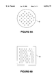
- FIGS. 6a and 6b are side views in elevation of the vat lid of the apparatus depicted in FIG. 1.
- FIG. 1 An embodiment of the complete RP system according to the invention is illustrated in FIG. 1.
- a programmed computer 10 for generating cross-sectional patterns 10.
- a light source 12 a reflective spatial light modulator (SLM) 11, optics 44 (shown in FIG. 3 only) for projecting a reflected pixel image 13 from the SLM 11 to a photoresin 16 contained in a vat or reservoir 17, and a build support piston 15 are all controlled by the computer 10.
- SLM reflective spatial light modulator
- optics 44 shown in FIG. 3 only
- the Projection Subsystem projects the cross-sectional image of the model onto the resin surface 18 and contains the following components: the light source 12, the SLM 11, a shutter (not shown) and the optics 44 (FIG. 3).
- the SLM 11 interfaces with the control computer 10, which provides the data for the image to project.
- the computer 10 analyzes the 3D CAD data and mathematically "slices" the solid model into layers of programmed thickness or Z-axis height. As illustrated in FIG. 2, the computer 10 then overlays a map or grid 2 of the pixel layout on the SLM 11.
- FIG. 2 shows an array of pixels in an (x, y) grid overlaid on a sample cross-sectional image. For a desired cross-sectional pattern to solidify, certain pixels must be toggled to an ON position for a sufficient exposure time to harden the segments of the photopolymer resin 16. Areas where light is not reflected (OFF) will remain liquid. As shown in FIG.
- each pixel 40 may be switched to an ON position 42 to reflect the light source 12 toward a small segment 45 of the resin 16 (referred to hereinafter as a pixel resin segment as distinct from a pixel of the SLM 11) or to an OFF position 41 to deflect light away in a direction 43 by rotating a mirror surface 46.
- a pixel 40 must be maintained in the ON state long enough to apply the required light energy to solidify to a programmed depth. This pixelating, allows light exposure of the programmed pattern onto the liquid surface, and causes the solidification of a thin surface layer.
- layer thickness may be varied by the computer 10. Varying layer thickness allows optimum Z-axis resolution and speed and allows the computer 10 to compensate for changing model shapes. For example, the apparatus builds layers as thin as possible in order to avoid a stair stepping phenomenon in the sloping sides of an object. In practical application, a layer must be thick enough to adhere to the previous layer. In addition, the computer 10 may select to build layers at maximum penetration depth in order to achieve maximum build speed. The thick layers provide better strength and integrity of the completed model. This invention allows the computer 10 to make layer thickness decisions based on these criteria.
- the computer 10 calculates the ON time for each pixel based on the resin 16 properties, layer thickness (cure depth) required, and light intensity.
- a light source 12 like the Cermax Xenon Illuminator from ILC Technology can provide a good source of UV light in the wavelength range of 325 to 360 nm.
- a typical output of these lamps has a Gaussian profile. This leads to greater illumination near the center of the image projection. Based on the characteristics of the light source 12 and its expected output, the irradiance of the pixels and the image projection can be estimated.
- a more precise method is to measure the light output with a sensing device in order to accurately define the light irradiance H.sub.(x, y) projected by each pixel of the SLM 11.
- the exposure time (ON time) of each pixel is a function as related by the working curve equation as follows:
- the exposure time of each layer and pixel must be adjusted as the light source 12 loses intensity with extended use.
- the computer 10 compensates by adjusting the ON time of individual pixels.
- the light source 12 may be filtered or collimated or polarized through optics not shown to provide accurate projection of the radiation required to solidify the chosen resin 16 in the cross-sectional image.
- Some popular resins 16 require a wavelength in the long UV range of 325 to 360 nm, however, any appropriate source of radiation may be used.
- the pixel resolution may not always match the programmed shape. In some cases, a pixel may require a "partial" ON status.
- the computer 10 also determines the ON/OFF status of these partial pixels based on the desired surface finish of the model. Typical decision factors may be based on the percent of pixel that is ON the image. Other factors may include the status of adjacent pixels and the preceding and subsequent layers.
- the preferred embodiment of the invention uses a reflective SLM 11 from Texas Instruments called a digital micromirror device (DMD).
- DMD digital micromirror device
- This device is described in U.S. Pat. No. 5,172,262 (Hombook, et al., issued Dec. 15, 1992), which is incorporated herein by reference, and is believed to be commercially available.
- the DMD array of micromirrors 46 (a single one of which is shown in FIG. 3) is constructed on a semiconductor memory chip, namely a static random access memory (SRAM) chip (not shown).
- SRAM static random access memory
- the individual addressable locations of the SRAM may be electrically charged in a high or low voltage state.
- the DMD mirrors 46 rotate toward the SRAM locations that are assigned a high voltage (5 V.C. nominal) by the computer 10.
- Typical dimensions of a DMD pixel 40 are 0.017 mm ⁇ 0.017 mm with aluminum reflective surfaces. Projection enlargements must consider the final reflected pixel image size and the resolution requirements of the model. If the projected pattern is too large, the reflected pixel image will become larger than the required resolution.
- Each pixel mirror 46 is constructed over two opposing SRAM locations allowing the mirror 46 to be biased toward either address location. In this way, two separate reflective states are achieved, which allows light to be reflected from each pixel onto or away from the pixel resin segment.
- the reflective surface of each pixel is 0.017 mm square.
- the projection optics are selected to magnify the reflected image from the DMD. Due to the importance of surface quality, the projected pixel size must be balanced with the overall projected image size. For example, a magnification of 9 ⁇ will project each image from 0.017 mm (0.7 mils) up to 0.153 mm (6 mils). This is an acceptable image resolution for most modeling applications.
- the build area for an array of 800 ⁇ 600 micromirrors 46 projected with 9 ⁇ magnification is 122 ⁇ 92 mm (4.8 ⁇ 3.6 square inches). This is probably smaller than desired for most part building applications, but larger size arrays are already coming into production.
- the resolution and part build area may be adjusted through the selection of optical components. These optics may include an automated zoom option to adjust the build area and resolution as required for the programmed part. Based on the chosen resolution, the grid or map of the projected image as shown in FIG. 2 must be sized accordingly. Exposure times must be adjusted since the enlargement of the projected image causes a proportional reduction of the irradiance, H.sub.(x, y).
- the SLM 11 turns the pixels ON to project the image.
- the shutter (not shown) is opened to allow light onto the SLM 11, and the light is reflected onto the resin 16 below with the shape of the cross-sectional image.
- the shutter mechanism may be eliminated by turning the light source 12 on and off as required or by setting all pixels OFF. However, cycling the light source 12 may reduce its life.
- the shutter is held open for the longest required pixel ON time for that layer. As the ON time t ON (x, y) expires for each pixel, it is toggled to OFF for the remainder of the layer exposure. After the layer exposure is complete, the pixels are reset, and the next layer may be formed.
- An alternate embodiment allows the ON pixels' state to be toggled during the exposure. This has the added advantage of pulse curing the resin 16.
- the curing process is actually polymerization of the resin 16. This is a process of linking together small monomer molecules into larger polymer molecules. By pulsing the radiation that initiates this process, e.g., by opening and closing the shutter or by rotating the micromirrors 46, a higher degree of polymerization or cross-linking of the molecules can be achieved. This is due to a higher molecular flow that allows a larger number of monomers to flow to the location where polymerization may occur. This higher flow reduces one of the principal reactions that lead to termination of the polymerization process.
- Occlusion represents one of the major terminators of the polymerization process and, therefore, reduced occlusion leads to a higher degree of cross-linking.
- advantages of higher polymerization are an increased green-strength and reduced curl and warp.
- the pixels are toggled with pulse width modulation (PWM) techniques.
- PWM pulse width modulation
- a square wave pulse input can accomplish the desired pulsing.
- the t ON (x, y) is the sum of the ON time for each pulse. For example, if the pixel is toggle ON 50% and OFF 50%, then t ON (x, y) must be doubled to achieve the required exposure time.
- the second subsystem is the Layer Forming Subsystem that creates the thin layers of resin 16 for building the part 14.
- This system is responsible for creating the layers of photopolymer resin 16 of the programmed thickness one after the other.
- the Layer Forming Subsystem comprises the following components: piston 15, resin 16, reservoir 17, imaging forming build surface 18, filter 19, volume compensator 20, piston arm 21, various valves (table return valve 22, fill valve 23, and transfer valve 26) for controlling the flow of the liquid resin 16, fill tube 24, fill tank 25, transfer tube 27, and dispense head 30.
- the preparation for building a part 14 requires that the lower section 17a of the reservoir 17 (i.e., the portion below the piston 15) be filled with the selected photopolymer resin 16.
- This lower reservoir 17a will source the resin 16 that is deposited for the layer-by-layer build.
- the fill tank 25 is placed in a position above the reservoir 17 to allow gravity to effect the flow of the resin 16.
- the fill tube 24 is attached between the lower reservoir 17a and the fill tank 25.
- the piston 15 is moved from a bottom position to a top position allowing the resin 16 to flow in behind it and fill the lower reservoir 17a.
- This step is not required before building each part since the resin 16 may safely remain in the reservoir 17 between builds. However, some resins 16 can spoil after extended periods in the reservoir 17.
- the piston 15 is returned to the top position to allow the part to be removed.
- the check valve or valves 22 in the piston 15 surface are opened in order to allow the resin 16 to flow by gravity back into the lower reservoir 17a thus preparing for the next build.
- This return valve contains a filter 19 to remove defects or particles from the previously used resin 16.
- the valve 22 is closed to prevent the flow of resin 16 from the lower reservoir 17a through the piston 15.
- the fill valve 23 in the fill tube 24 is closed and the fill tank 25 may be placed below the reservoir 17. This will later facilitate the removal of resin 16 for cleaning or to exchange with another resin 16.
- the piston 15 is moved down a distance equal to the programmed layer thickness.
- the piston 15 position is changed by a motion control (not shown which is operated by the computer 10) and capable of fine position and speed control. Suitable such systems include stepper motors or servomotors. This downward motion will displace the amount of resin 16 required to form a layer.
- the resin 16 is forced from the lower reservoir 17a through the transfer tube 27 and deposited onto the top surface of the piston 15.
- the transfer tube 27 may contain a check valve 26 to insure that resin 16 does not flow back into the lower reservoir 17a.
- the transfer tube 27 outlet is positioned over the reservoir 17.
- the transfer tube 27 typically feeds the resin 16 through nozzles or apertures or spray heads 30 that dispense the resin 16 in an even layer. Note that although only one head 30 is shown, in actual practice there would be a plurality of such heads 30 depositing the resin across the surface of the reservoir 17.
- the transfer tubes feed through nozzles or apertures or spray heads positioned directly over the previously formed laminae. They are positioned over the reservoir surface by a reservoir lid 61.
- the lid 61 is positioned over the build area by a solenoid or other actuating device.
- a typical lid shape and pattern that may be used to provide fast and even layering is shown in FIGS. 6a and 6b only.
- the reservoir lid 61 has other advantages. It is comprised of materials that do not allow the transmittance of radiation that may cure the resin. This protects the resin 16 from stray light radiation, and may also protect from solvents used in cleaning the machine.
- the exterior (top) of the cap may contain sensors to test light irradiance with a test routine between layers. This allows calibration of the irradiance information during the layering routine and without impinging any radiation onto the resin.
- One test routine is to open the shutter with all pixels ON to measure the irradiance.
- Another routine is to test individual pixels ON in varying sectors in order to estimate the irradiance from pixels in those sectors. The data from these test sensors may be used in calculations of the t ON (x, y) described above.
- this layering method is two-fold. First, the parts are moved together with the surrounding fluid. This avoids the forces that are put on the fragile parts if they are submerged and lifted through the surrounding viscous liquid. Secondly, the method allows a fast means for depositing an accurate one layer thick volume of the liquid resin 16. The thickness of the volume of resin 16 deposited on top of the model will match the downward displacement of the model, allowing a very accurate layer thickness.
- volume of resin 16 displaced is the cross-sectional area of the piston 15 times the Z-axis travel distance of the piston 15. Since the piston arm reduces the area of the piston 15, a volume compensator 20 must be placed above the piston 15 to equalize the cross-sectional area. This is usually the same shape and volume as the piston arm 21.
- the volume compensator 20 may include a bladder or other means for increasing or decreasing the volume of the compensator in order to adjust the liquid level of the build surface. Alternatively, the computer 10 could automatically control the amount of resin 16 to provide such compensation.
- the filling of new resin 16 in the Layer Forming Subsystem requires the transfer tube 27 to be primed. This is accomplished during the fill process, by opening the transfer valve 26 to allow the resin 16 to flow through the transfer tube 27.
- the fill tank 25 upper position uses gravity to facilitate the flow of the resin 16.
- the valve 26 remains open until all air is removed from the transfer tube 27.
- a reservoir 17 lid (not shown) is usually positioned over an additional container to catch any spilled resin 16.
- an alternate method may be used. In this alternate method, the reservoir 17 lid is positioned above the build area and excess resin 16 that flows through during the primer process, is allowed to fill the build area. This can lead to uncertainties in the liquid level for which adjustments must be made.
- a build surface other than the piston 15 top surface must be placed into the build area.
- the new build surface is usually a wire mesh or foam that allows the liquid resin 16 to permeate.
- the liquid level is then adjusted with reference to this new build surface.
- the computer 10 moves the piston 15 down to align the liquid level with the new build surface 18.
- the first layer of the model is built from the new build surface 18 as the starting point. Measurements of the liquid level are measured by various devices including floats or reflective sensors.
- the computer 10 compares the measurements and adjusts the piston 15 position to compensate.
- An external displacement pump may be used to make additional adjustments of the liquid level by adding resin 16 from an external reservoir (not shown) or the fill tank 25.
- Shrinkage is a result of the polymerization process that causes a volumetric shrinkage with increased molecular bonding. Shrinkage may be compensated for with a dispensing pump that adds small amounts of resin 16 to the build area. This compensator may add small amounts of liquid to maintain the curing surface at the desired distance from the Projection Subsystem. Alternately, a zoom type optical lens may be used to adjust the imaging plane of the Projection Subsystem in order to match the curing surface. The amount of shrinkage is dependent on the resin 16 properties as well as volume of the solid model cured. Models with a large relative volume will require additional adjustments to the liquid level of the cure surface. The amount of compensation for shrinkage may be calculated from the volume of the solid model and the characteristics of the resin 16 used. Various measuring techniques may also be employed to measure the liquid surface level.
- the shrinkage effect mentioned above can be controlled and reduced by this invention due to the digital exposure control.
- the layers cure through incremental exposure.
- the curl found during the cure of a newly added layer is caused by over curing the new layer too early.
- Over curing is required to laminate the layers of the model.
- the overcure serves to laminate the layers of resin 16 that have varying degrees of polymerization.
- the newer layer is shrinking at a faster rate during its polymerization than the previous layer that is more fully hardened. If the overcure laminates these layers too early, the shrinkage of the new layer causes the curl.
- the exposure is provided in stages to reduce the curl.
- An exposure capable of curing the resin 16 to a depth less than the layer thickness is provided to partially cure the new layer. Then a pause in the exposure allows higher cross-linking to occur in the newly formed layer. This brings the polymerization and shrinkage rate in the two layers to a similar level. Then in a subsequent exposure, additional curing allows the overcure to laminate the two layers together.
- Layer Binding An additional method using the digital exposure is called Layer Binding (LB). This method avoids stratifying the layers found with SLA and SGC systems.
- LB Layer Binding
- a programmed layer pattern 32 is partially exposed in a pixel pattern as chosen by the computer 10. In this pattern, or ones similar, some pixels are underexposed 33, leaving them in an uncured state that is not completely solidified.
- the pixel above an uncured state must remain ON for a longer period to expose both the current and previous layers until solidified.
- a pixel segment that is exposed and solidified through some succeeding layer acts as a post or peg that binds the two layers together. This results in an interlocking of layers and avoids de-lamination.
- the Layer Binding method reduces the internal stress between adjacent layer laminations as found in other RP systems.
- the new layer of resin deposited on the build surface 18 may be allowed to flow over the area until it reaches a uniform thickness. However, this can take some time depending on the viscosity of the resin 16. Methods to reduce the time of spreading the layer may include wiper blades, brushes, wires, or compressed air. As previously mentioned, the transfer tube 27 may feed into spray head nozzles 30 that distribute the liquid more evenly across the cross section. Additionally, the transfer tube 27 may contain heating elements that elevate the temperature of the resin 16. The advantage of heating the resin is to decrease the viscosity for easier layering and to allow more rapid and complete curing of the resin 16 during the exposure phase. This method of heating resin in the transfer tubes heats only the resin layer immediately affected and is more efficient than heating the entire reservoir 17 of liquid resin 16 or the machine environment.
- the computer 10 coordinates the actions of the two subsystems.
- the Layer Forming Subsystem must complete formation of the layer and remove the cap before the image is projected. Additional wait times may be required for the resin layer to flow out to a flat layer.
- the Projection Subsystem may proceed to calculate the ON times for each pixel, but must then hold before opening the shutter and projecting light.
- FIG. 5 shows a step-by-step operation of the apparatus when performing the Layer Binding method. Note that steps S21, S23 are performed in parallel with steps S22, S24.
- step S20 the computer 10 generates the two-dimensional patterns that comprise a three-dimensional object to be formed.
- step S21 the computer 10 pixelates the graphical pattern thus determining which pixels 40 of the SLM 11 must be turned to the ON state in order to solidify the laminate layer. Also in this step, the computer 10 will determine which pixel resin segments 45 to partially cure into a gel state in order to create layer binding.
- step S22 the computer 10 lowers the build support piston 15 thus depositing the liquid layer of the programmed layer thickness onto the build surface 18.
- the RP system may even the layer by wiping away any excess liquid or bubbles and, thus, increasing accuracy of the layer thickness.
- step S23 the computer 10 activates the correct pixels 40 of the SLM 11 by controlling activation means to rotate the pixel mirror 46 to turn ON a pixel 40.
- step S24 optics 44 are positioned to project light to the correct pattern image size 13. A projection should not be enlarged beyond the desired resolution, which is dependent on the size of a projected pixel image.
- step S25 the light source 12 is activated to deliver radiation energy to the SLM 11 and reflect onto the liquid surface 18.
- each pixel 40 maintains the ON state long enough to solidify the programmed layer thickness.
- the computer 10 controls the radiation energy delivered by shortening or extending the pixel ON time, and may therefore create layer binding as previously discussed.
- step S27 the computer 10 determines that all pattern slices have not been projected, i.e., the model is incomplete, then the process proceeds to step S28 where the computer 10 moves ahead one slice in the process and resumes with steps S21 and S22. If at step S27 the computer 10 determines that the model is complete, then the system will proceed to step S29.
- step S29 the build support piston 15 rises out of the liquid medium and the model may be removed.
- step S30 the SLM 11 or other means may be utilized to create a three-dimensional optical scan of the completed model.
- the computer 10 can recommend post process operator actions in step S31. Examples of recommended actions include removing or adding material or making programming or mechanical adjustments.
- Flexibility--The handling system described herein allows simplified removal and addition of the resin. This allows more flexibility to choose from the growing selection of photohardenable materials.
- the exchange of the light source is lower cost than exchanging the laser in other systems. This allows selection of resins that require other wavelengths. This flexibility is important as research into photohardenable materials with ceramic particulate or other additives leads to improved model quality.
- the system has the flexibility of varying pixel resolution to allow the choice of small high-resolution parts or large lower resolution parts.
- the source 12 radiates "light,” it should be apparent that other types of radiant energy could also suffice, provided that the radiant energy is of a wavelength and intensity to cause the resin to cure.
- a particular type of spatial "light” modulator has been disclosed and described as being the preferred device for modulating the radiant energy which impinges upon the resin, other types of spatial radiant energy modulators could be used. What is required is that the spatial light modulator have an array of pixel elements which are individually controllable, preferably digitally, for modulating the radiant energy beam projected from a radiant energy source on a pixel by pixel basis, to form a series of time sequential images of the cross-sectional laminae of the object being modeled.
- the spatial light modulator might be a light transmissive device which can control radiant energy passing through it on a pixel-by-pixel basis.
- a plurality of spatial light modulators could be used to increase the build area while improving the resolution by reducing the required magnification.
- photohardenable resins or adhesives or even non-liquid materials which will harden in the UV or even non-UV wavelengths might be used.
- finely powered photo-hardenable materials might be used.
- the present invention contemplates a non-laser light source because of the advantages heretofore described, in applications where a higher power density is required, a laser may be used as the light source.
Landscapes
- Chemical & Material Sciences (AREA)
- Engineering & Computer Science (AREA)
- Materials Engineering (AREA)
- Manufacturing & Machinery (AREA)
- Physics & Mathematics (AREA)
- Mechanical Engineering (AREA)
- Optics & Photonics (AREA)
Abstract
Description
Claims (55)
Priority Applications (1)
| Application Number | Priority Date | Filing Date | Title |
|---|---|---|---|
| US09/040,829 US6051179A (en) | 1997-03-19 | 1998-03-18 | Apparatus and method for production of three-dimensional models by spatial light modulator |
Applications Claiming Priority (2)
| Application Number | Priority Date | Filing Date | Title |
|---|---|---|---|
| US3936297P | 1997-03-19 | 1997-03-19 | |
| US09/040,829 US6051179A (en) | 1997-03-19 | 1998-03-18 | Apparatus and method for production of three-dimensional models by spatial light modulator |
Publications (1)
| Publication Number | Publication Date |
|---|---|
| US6051179A true US6051179A (en) | 2000-04-18 |
Family
ID=21905071
Family Applications (1)
| Application Number | Title | Priority Date | Filing Date |
|---|---|---|---|
| US09/040,829 Expired - Fee Related US6051179A (en) | 1997-03-19 | 1998-03-18 | Apparatus and method for production of three-dimensional models by spatial light modulator |
Country Status (2)
| Country | Link |
|---|---|
| US (1) | US6051179A (en) |
| WO (1) | WO1998041944A1 (en) |
Cited By (121)
| Publication number | Priority date | Publication date | Assignee | Title |
|---|---|---|---|---|
| EP1179411A2 (en) * | 2000-08-11 | 2002-02-13 | 3D Systems, Inc. | Stereolithography |
| US6391245B1 (en) * | 1999-04-13 | 2002-05-21 | Eom Technologies, L.L.C. | Method for creating three-dimensional objects by cross-sectional lithography |
| US6407849B1 (en) * | 1999-07-01 | 2002-06-18 | Creoscitex Corporation Ltd | Method and system for illumination using laser diode bar and microlenses array of same pitch |
| US20020164069A1 (en) * | 2001-02-16 | 2002-11-07 | Fuji Photo Film Co., Ltd. | Optical modeling device and exposure unit |
| US6500378B1 (en) | 2000-07-13 | 2002-12-31 | Eom Technologies, L.L.C. | Method and apparatus for creating three-dimensional objects by cross-sectional lithography |
| US20030033128A1 (en) * | 2001-05-08 | 2003-02-13 | Fuji Photo Film Co., Ltd | Optical modeling method |
| US20030173713A1 (en) * | 2001-12-10 | 2003-09-18 | Wen-Chiang Huang | Maskless stereo lithography method and apparatus for freeform fabrication of 3-D objects |
| JP2004505439A (en) * | 2000-07-16 | 2004-02-19 | ボード・オブ・リージエンツ,ザ・ユニバーシテイ・オブ・テキサス・システム | High resolution overlay alignment method and system for transfer lithography |
| US6731991B1 (en) * | 1999-07-19 | 2004-05-04 | Laser Force, Inc. | System for projecting light on a work surface to produce an image for tracing |
| US20040160590A1 (en) * | 2003-02-19 | 2004-08-19 | Dainippon Screen Mfg. Co., Ltd. | Photo-fabrication apparatus |
| US6792327B1 (en) * | 1999-08-19 | 2004-09-14 | Bae Systems Plc | Stereolithographic method for combining components of varying densities |
| US20050085927A1 (en) * | 2000-05-12 | 2005-04-21 | Incs Inc. | Method and device for executing work consisting of a plurality of steps under computer control |
| US20050205232A1 (en) * | 2003-07-10 | 2005-09-22 | General Electric Company | Synthetic model casting |
| US20050248062A1 (en) * | 2004-05-10 | 2005-11-10 | Alexandr Shkolnik | Process for the production of a three-dimensional object with resolution improvement by "pixel-shift" |
| EP1614488A1 (en) * | 2004-07-06 | 2006-01-11 | General Electric Company | Casting method using a synthetic model produced by stereolithography |
| US20060100734A1 (en) * | 2004-10-28 | 2006-05-11 | Sheng-Jye Huang | Method for rapid prototyping by using linear light as sources |
| US7052263B2 (en) * | 2001-04-20 | 2006-05-30 | Envisiontec Gmbh | Apparatus for manufacturing a three-dimensional object |
| US20060161287A1 (en) * | 2005-01-14 | 2006-07-20 | Simonis Steven F | Rapid prototyping and manufacturing of photocured objects using LCD panel as programmably variable photomask |
| US20060198918A1 (en) * | 2005-03-03 | 2006-09-07 | Dainippon Screen Mfg. Co., Ltd. | Stereolithography apparatus |
| US20060239588A1 (en) * | 2005-04-01 | 2006-10-26 | 3D Systems, Inc. | Edge smoothness with low resolution projected images for use in solid imaging |
| US7128866B1 (en) * | 1998-10-12 | 2006-10-31 | Dicon A/S | Rapid prototyping apparatus and method of rapid prototyping |
| US20070231421A1 (en) * | 2006-04-03 | 2007-10-04 | Molecular Imprints, Inc. | Enhanced Multi Channel Alignment |
| US20070257055A1 (en) * | 2006-05-03 | 2007-11-08 | 3D Systems, Inc. | Material delivery system for use in solid imaging |
| US20070259066A1 (en) * | 2006-05-03 | 2007-11-08 | 3D Systems, Inc. | Material delivery tension and tracking system for use in solid imaging |
| US7318718B2 (en) * | 2000-06-06 | 2008-01-15 | Teijin Seiki Co., Ltd. | Stereolithographic apparatus and method for manufacturing three-dimensional object |
| US20080021586A1 (en) * | 2006-07-19 | 2008-01-24 | Volker Schillen | Method and device for producing a three-dimensional object, and computer and data carrier useful therefor |
| US20080054531A1 (en) * | 2006-08-29 | 2008-03-06 | 3D Systems, Inc. | Wall Smoothness, Feature Accuracy and Resolution In Projected Images Via Exposure Levels In Solid Imaging |
| US20080170112A1 (en) * | 2007-01-17 | 2008-07-17 | Hull Charles W | Build pad, solid image build, and method for building build supports |
| US20080169589A1 (en) * | 2007-01-17 | 2008-07-17 | Sperry Charles R | Solid imaging apparatus and method |
| US20080171284A1 (en) * | 2007-01-17 | 2008-07-17 | Hull Charles W | Method for Removing Excess Uncured Build Material in Solid Imaging |
| US20080169586A1 (en) * | 2007-01-17 | 2008-07-17 | Hull Charles W | Imager Assembly and Method for Solid Imaging |
| US20080179786A1 (en) * | 2007-01-17 | 2008-07-31 | Sperry Charles R | Cartridge for solid imaging apparatus and method |
| US20080179787A1 (en) * | 2007-01-17 | 2008-07-31 | Sperry Charles R | Elevator and method for tilting solid image build platform for reducing air entrainment and for build release |
| US20080181977A1 (en) * | 2007-01-17 | 2008-07-31 | Sperry Charles R | Brush assembly for removal of excess uncured build material |
| US20080206383A1 (en) * | 2007-01-17 | 2008-08-28 | Hull Charles W | Solid Imaging System with Removal of Excess Uncured Build Material |
| US20080226346A1 (en) * | 2007-01-17 | 2008-09-18 | 3D Systems, Inc. | Inkjet Solid Imaging System and Method for Solid Imaging |
| US20080231731A1 (en) * | 2007-01-17 | 2008-09-25 | Hull Charles W | Imager and method for consistent repeatable alignment in a solid imaging apparatus |
| US20090130449A1 (en) * | 2007-10-26 | 2009-05-21 | Envisiontec Gmbh | Process and freeform fabrication system for producing a three-dimensional object |
| US20090142436A1 (en) * | 2007-12-03 | 2009-06-04 | Sony Corporation | Optical shaping apparatus and optical shaping method |
| US20090250835A1 (en) * | 2006-09-27 | 2009-10-08 | Jsr Corporation | Method for manufacturing molding die and method for manufacturing molded product |
| US20090256284A1 (en) * | 2008-04-14 | 2009-10-15 | Michael Christopher Maguire | Method for producing ceramic stereolithography parts |
| US20100003619A1 (en) * | 2008-05-05 | 2010-01-07 | Suman Das | Systems and methods for fabricating three-dimensional objects |
| US7708542B2 (en) | 2000-07-16 | 2010-05-04 | Board Of Regents, The University Of Texas System | Device for holding a template for use in imprint lithography |
| US20100125356A1 (en) * | 2008-11-18 | 2010-05-20 | Global Filtration Systems | System and Method for Manufacturing |
| US7780893B2 (en) | 2006-04-03 | 2010-08-24 | Molecular Imprints, Inc. | Method of concurrently patterning a substrate having a plurality of fields and a plurality of alignment marks |
| US7783371B2 (en) | 2006-04-28 | 2010-08-24 | Envisiontec Gmbh | Device and method for producing a three-dimensional object by means of mask exposure |
| US7785526B2 (en) | 2004-07-20 | 2010-08-31 | Molecular Imprints, Inc. | Imprint alignment method, system, and template |
| US7845930B2 (en) | 2004-05-07 | 2010-12-07 | Envisiontec Gmbh | Process for the production of a three-dimensional object with an improved separation of hardened material layers from a construction plane |
| US7892474B2 (en) | 2006-11-15 | 2011-02-22 | Envisiontec Gmbh | Continuous generative process for producing a three-dimensional object |
| US7894921B2 (en) | 2006-04-28 | 2011-02-22 | Envisiontec Gmbh | Device and method for producing a three-dimensional object by means of mask exposure |
| US20110089610A1 (en) * | 2009-10-19 | 2011-04-21 | Global Filtration Systems | Resin Solidification Substrate and Assembly |
| US8048359B2 (en) | 2008-10-20 | 2011-11-01 | 3D Systems, Inc. | Compensation of actinic radiation intensity profiles for three-dimensional modelers |
| CN101109898B (en) * | 2006-07-19 | 2012-08-15 | 德国Envisiontec股份有限公司 | Method for producing a three-dimensional object |
| US20120248657A1 (en) * | 2011-03-29 | 2012-10-04 | Technische Universitat Wien | Method for the layered construction of a shaped body made of highly viscous photopolymerizable material |
| US8348655B2 (en) * | 2008-01-09 | 2013-01-08 | Sony Corporation | Optical molding apparatus, optical molding method, and optically molded product |
| USRE43955E1 (en) | 2004-05-10 | 2013-02-05 | Envisiontec Gmbh | Process for the production of a three-dimensional object with resolution improvement by pixel-shift |
| WO2013170311A1 (en) * | 2012-05-15 | 2013-11-21 | Zydex Pty Ltd | Apparatus and method for making an object |
| US20140076749A1 (en) * | 2012-09-14 | 2014-03-20 | Raytheon Company | Variable density desiccator housing and method of manufacturing |
| US20140101409A1 (en) * | 2012-10-10 | 2014-04-10 | Altera Corporation | 3d memory based address generator |
| US8845316B2 (en) | 2007-07-04 | 2014-09-30 | Envisiontec Gmbh | Process and device for producing a three-dimensional object |
| US20150056320A1 (en) * | 2012-07-27 | 2015-02-26 | Dws S.R.L. | Cartridge for a stereolithographic machine, sterolithographic machine comprising said cartridge and method of manufacturing said cartridge |
| US9034237B2 (en) | 2012-09-25 | 2015-05-19 | 3D Systems, Inc. | Solid imaging systems, components thereof, and methods of solid imaging |
| WO2015189837A1 (en) * | 2014-06-08 | 2015-12-17 | Massivit 3D Printing Technologies Ltd. | A method and appratus for manufacture of 3d objects |
| US9223202B2 (en) | 2000-07-17 | 2015-12-29 | Board Of Regents, The University Of Texas System | Method of automatic fluid dispensing for imprint lithography processes |
| JP2016501139A (en) * | 2012-11-08 | 2016-01-18 | ディーディーエム システムズ, インコーポレイテッド | System and method for processing three-dimensional objects |
| US20160096332A1 (en) * | 2014-10-02 | 2016-04-07 | Xyzprinting, Inc. | Three dimensional printing apparatus and printing method thereof |
| US9354510B2 (en) | 2011-12-16 | 2016-05-31 | Taiwan Semiconductor Manufacturing Company, Ltd. | EUV mask and method for forming the same |
| US20160200044A1 (en) * | 2013-04-24 | 2016-07-14 | The Board Of Regents Of The University Of Texas System | Cartridge-based 3d printing system |
| US9452567B2 (en) | 2013-08-27 | 2016-09-27 | Kao-Chih Syao | Stereolithography apparatus |
| WO2016201326A1 (en) * | 2015-06-10 | 2016-12-15 | Ipg Photonics Corporation | Multiple beam additive manufacturing |
| US9527244B2 (en) | 2014-02-10 | 2016-12-27 | Global Filtration Systems | Apparatus and method for forming three-dimensional objects from solidifiable paste |
| WO2017043747A1 (en) * | 2015-09-08 | 2017-03-16 | 임은석 | 3d printer and method for manufacturing 3d object |
| EP3157734A2 (en) * | 2014-06-18 | 2017-04-26 | Heraeus Kulzer GmbH | Method for producing three-dimensional objects by rapid prototyping with increased efficiency |
| EP2605805A4 (en) * | 2010-08-20 | 2017-08-16 | Case Western Reserve University | Continuous digital light processing additive manufacturing of implants |
| EP2782705B1 (en) | 2011-11-22 | 2017-09-13 | MTU Aero Engines GmbH | Method of generative producing a component using a laser beam before, during and after the assembly |
| WO2016181378A3 (en) * | 2015-05-13 | 2017-11-09 | Massivit 3D Printing Technologies Ltd | A method and apparatus for manufacture of 3d objects |
| EP2433778A3 (en) * | 2010-09-27 | 2017-12-27 | Materialise NV | Method for reducing differential shrinkage in stereolithography |
| US20180056604A1 (en) * | 2016-08-26 | 2018-03-01 | General Electric Company | Energy management method for pixel-based additive manufacturing |
| US9933632B2 (en) | 2014-03-26 | 2018-04-03 | Indizen Optical Technologies, S.L. | Eyewear lens production by multi-layer additive techniques |
| US9952448B2 (en) | 2014-03-26 | 2018-04-24 | Indizen Optical Technologies, S.L. | Eyewear lens production by additive techniques |
| US20180243986A1 (en) * | 2015-03-16 | 2018-08-30 | Lg Electronics Inc. | 3d printing apparatus |
| US10162264B2 (en) | 2012-03-22 | 2018-12-25 | The Regents Of The University Of Colorado, A Body Corporate | Liquid deposition photolithography |
| US20190016052A1 (en) * | 2017-07-11 | 2019-01-17 | Daniel S. Clark | 5d part growing machine with volumetric display technology |
| US20190126536A1 (en) * | 2017-11-02 | 2019-05-02 | General Electric Company | Cartridge vat-based additive manufacturing apparatus and method |
| US20190176388A1 (en) * | 2017-12-07 | 2019-06-13 | Canon Kabushiki Kaisha | Method for manufacturing three-dimensional shaped object, additive manufacturing apparatus, and article |
| US10336055B2 (en) | 2008-05-05 | 2019-07-02 | Georgia Tech Research Corporation | Systems and methods for fabricating three-dimensional objects |
| US10391708B2 (en) * | 2013-07-16 | 2019-08-27 | Schultheiss Gmbh | Method and device for producing a three-dimensional object and exposure mask generating apparatus |
| WO2020002776A1 (en) * | 2018-06-28 | 2020-01-02 | Planmeca Oy | Stereolithography apparatus equipped with resin collecting mechanism and method of operating said apparatus |
| US10610341B2 (en) * | 2014-06-18 | 2020-04-07 | Heraeus Kulzer Gmbh | More efficient method for producing three-dimensional objects by means of a rapid prototyping process |
| WO2020132093A1 (en) * | 2018-12-20 | 2020-06-25 | Jabil Inc. | Apparatus, system and method of heat filtering for additive manufacturing |
| US10737479B2 (en) | 2017-01-12 | 2020-08-11 | Global Filtration Systems | Method of making three-dimensional objects using both continuous and discontinuous solidification |
| US20200338828A1 (en) * | 2019-04-29 | 2020-10-29 | Mighty Buildings, Inc. | System for Obtaining a Photopolymerized Prepolymer |
| US10821669B2 (en) | 2018-01-26 | 2020-11-03 | General Electric Company | Method for producing a component layer-by-layer |
| US10821668B2 (en) | 2018-01-26 | 2020-11-03 | General Electric Company | Method for producing a component layer-by- layer |
| CN113508026A (en) * | 2019-02-20 | 2021-10-15 | 通用电气公司 | Method and apparatus for build thickness control in additive manufacturing |
| US11148357B2 (en) * | 2017-02-13 | 2021-10-19 | Carbon, Inc. | Method of making composite objects by additive manufacturing |
| US11179926B2 (en) | 2016-12-15 | 2021-11-23 | General Electric Company | Hybridized light sources |
| US11179891B2 (en) | 2019-03-15 | 2021-11-23 | General Electric Company | Method and apparatus for additive manufacturing with shared components |
| US11254052B2 (en) | 2017-11-02 | 2022-02-22 | General Electric Company | Vatless additive manufacturing apparatus and method |
| US11254053B2 (en) | 2019-02-28 | 2022-02-22 | 3D Systems, Inc. | High resolution three-dimensional printing system |
| CN114179361A (en) * | 2017-03-22 | 2022-03-15 | 爱尔康公司 | 3D printing of intraocular lenses with smooth curved surfaces |
| US11318555B2 (en) * | 2017-01-17 | 2022-05-03 | Reliance Rg Limited | Charged particle beam control during additive layer manufacture |
| US11351724B2 (en) | 2017-10-03 | 2022-06-07 | General Electric Company | Selective sintering additive manufacturing method |
| CN114643714A (en) * | 2020-12-19 | 2022-06-21 | 深圳市创想三维科技有限公司 | Photocuring 3D printing method, electronic device and storage medium |
| US11420384B2 (en) | 2017-10-03 | 2022-08-23 | General Electric Company | Selective curing additive manufacturing method |
| US11453171B2 (en) | 2018-04-09 | 2022-09-27 | Nederlandse Organisatie Voor Toegepast-Natuurwetenschappelijk Onderzoek Tno | Method of apparatus for forming an object by means of additive manufacturing |
| US11590691B2 (en) | 2017-11-02 | 2023-02-28 | General Electric Company | Plate-based additive manufacturing apparatus and method |
| US11660807B2 (en) | 2018-11-01 | 2023-05-30 | Stratasys, Inc. | Method for build separation from a curing interface in an additive manufacturing process |
| US11731367B2 (en) | 2021-06-23 | 2023-08-22 | General Electric Company | Drive system for additive manufacturing |
| US11767514B2 (en) | 2017-05-25 | 2023-09-26 | Prellis Biologics, Inc | Three-dimensional printed organs, devices, and matrices |
| US11794412B2 (en) | 2019-02-20 | 2023-10-24 | General Electric Company | Method and apparatus for layer thickness control in additive manufacturing |
| US11813799B2 (en) | 2021-09-01 | 2023-11-14 | General Electric Company | Control systems and methods for additive manufacturing |
| US11826950B2 (en) | 2021-07-09 | 2023-11-28 | General Electric Company | Resin management system for additive manufacturing |
| WO2023246818A1 (en) * | 2022-06-23 | 2023-12-28 | 先临三维科技股份有限公司 | 3d printing control method and apparatus, electronic device and medium |
| US11865785B2 (en) | 2010-08-20 | 2024-01-09 | H. David Dean | Continuous digital light processing additive manufacturing of implants |
| US11919246B2 (en) | 2017-07-11 | 2024-03-05 | Daniel S. Clark | 5D part growing machine with volumetric display technology |
| US11951679B2 (en) | 2021-06-16 | 2024-04-09 | General Electric Company | Additive manufacturing system |
| US11958249B2 (en) | 2021-06-24 | 2024-04-16 | General Electric Company | Reclamation system for additive manufacturing |
| US11958250B2 (en) | 2021-06-24 | 2024-04-16 | General Electric Company | Reclamation system for additive manufacturing |
| US12172379B2 (en) | 2021-08-11 | 2024-12-24 | General Electric Company | Cleaning system for additive manufacturing |
| US12220870B2 (en) | 2023-11-27 | 2025-02-11 | H. David Dean | Continuous digital light processing additive manufacturing of implants |
Families Citing this family (6)
| Publication number | Priority date | Publication date | Assignee | Title |
|---|---|---|---|---|
| KR101601652B1 (en) * | 2014-05-07 | 2016-03-09 | 주식회사 캐리마 | 3D printer having device for circulation of photocurable resin |
| BR112017021657A2 (en) | 2015-04-07 | 2018-07-10 | Trio Labs Inc | method and apparatus for fabricating solids of arbitrary object shapes incorporating enhanced resolution background |
| US11376794B2 (en) | 2017-03-13 | 2022-07-05 | Euler3D Aps | Additive manufacturing apparatus and method |
| WO2019089007A1 (en) | 2017-10-31 | 2019-05-09 | Lawrence Livermore National Security, Llc | System and method for depth resolved parallel two-photon polymerization for scalable submicron additive manufacturing |
| WO2019133212A1 (en) | 2017-12-29 | 2019-07-04 | Lawrence Livermore National Security, Llc | System and method for submicron additive manufacturing |
| CN110394979B (en) * | 2018-04-25 | 2021-09-21 | 中国航发商用航空发动机有限责任公司 | Photocuring forming equipment |
Citations (38)
| Publication number | Priority date | Publication date | Assignee | Title |
|---|---|---|---|---|
| US2775758A (en) * | 1951-05-25 | 1956-12-25 | Munz Otto John | Photo-glyph recording |
| US4575330A (en) * | 1984-08-08 | 1986-03-11 | Uvp, Inc. | Apparatus for production of three-dimensional objects by stereolithography |
| US4752498A (en) * | 1987-03-02 | 1988-06-21 | Fudim Efrem V | Method and apparatus for production of three-dimensional objects by photosolidification |
| US4801477A (en) * | 1987-09-29 | 1989-01-31 | Fudim Efrem V | Method and apparatus for production of three-dimensional objects by photosolidification |
| US4945032A (en) * | 1988-03-31 | 1990-07-31 | Desoto, Inc. | Stereolithography using repeated exposures to increase strength and reduce distortion |
| US5011635A (en) * | 1989-05-18 | 1991-04-30 | Desoto, Inc. | Stereolithographic method and apparatus in which a membrane separates phases |
| US5015424A (en) * | 1988-04-18 | 1991-05-14 | 3D Systems, Inc. | Methods and apparatus for production of three-dimensional objects by stereolithography |
| US5104592A (en) * | 1988-04-18 | 1992-04-14 | 3D Systems, Inc. | Method of and apparatus for production of three-dimensional objects by stereolithography with reduced curl |
| US5106288A (en) * | 1988-04-11 | 1992-04-21 | Austral Asian Lasers Pty Ltd. | Laser based plastic model making workstation |
| US5130064A (en) * | 1988-04-18 | 1992-07-14 | 3D Systems, Inc. | Method of making a three dimensional object by stereolithography |
| US5139338A (en) * | 1988-11-10 | 1992-08-18 | Cubital Ltd. | Method and apparatus for volumetric digitization of 3-dimensional objects |
| US5139711A (en) * | 1989-12-25 | 1992-08-18 | Matsushita Electric Works, Ltd. | Process of and apparatus for making three dimensional objects |
| US5151813A (en) * | 1989-03-14 | 1992-09-29 | Sony Corporation | Method and apparatus for producing three-dimensional objects |
| US5157423A (en) * | 1991-05-08 | 1992-10-20 | Cubital Ltd. | Apparatus for pattern generation on a dielectric substrate |
| US5171490A (en) * | 1988-11-29 | 1992-12-15 | Fudim Efrem V | Method and apparatus for production of three-dimensional objects by irradiation of photopolymers |
| US5172262A (en) * | 1985-10-30 | 1992-12-15 | Texas Instruments Incorporated | Spatial light modulator and method |
| US5182055A (en) * | 1988-04-18 | 1993-01-26 | 3D Systems, Inc. | Method of making a three-dimensional object by stereolithography |
| US5182056A (en) * | 1988-04-18 | 1993-01-26 | 3D Systems, Inc. | Stereolithography method and apparatus employing various penetration depths |
| US5192469A (en) * | 1990-10-30 | 1993-03-09 | 3D Systems, Inc. | Simultaneous multiple layer curing in stereolithography |
| US5198159A (en) * | 1990-10-09 | 1993-03-30 | Matsushita Electric Works, Ltd. | Process of fabricating three-dimensional objects from a light curable resin liquid |
| US5217653A (en) * | 1991-02-18 | 1993-06-08 | Leonid Mashinsky | Method and apparatus for producing a stepless 3-dimensional object by stereolithography |
| US5247180A (en) * | 1991-12-30 | 1993-09-21 | Texas Instruments Incorporated | Stereolithographic apparatus and method of use |
| US5256340A (en) * | 1988-04-18 | 1993-10-26 | 3D Systems, Inc. | Method of making a three-dimensional object by stereolithography |
| US5273691A (en) * | 1988-04-18 | 1993-12-28 | 3D Systems, Inc. | Stereolithographic curl reduction |
| US5287435A (en) * | 1987-06-02 | 1994-02-15 | Cubital Ltd. | Three dimensional modeling |
| US5358673A (en) * | 1990-02-15 | 1994-10-25 | 3D Systems, Inc. | Applicator device and method for dispensing a liquid medium in a laser modeling machine |
| US5429908A (en) * | 1993-04-12 | 1995-07-04 | E. I. Du Pont De Nemours And Company | Exposure method for reducing distortion in models produced through solid imaging by forming a non-continuous image of a pattern which is then imaged to form a continuous hardened image of the pattern |
| US5460758A (en) * | 1990-12-21 | 1995-10-24 | Eos Gmbh Electro Optical Systems | Method and apparatus for production of a three-dimensional object |
| US5525051A (en) * | 1993-03-22 | 1996-06-11 | Sony Corporation | Optical molding apparatus |
| US5536467A (en) * | 1993-01-28 | 1996-07-16 | Eos Gmbh Electro Optical Systems | Method and apparatus for producing a three-dimensional object |
| US5545367A (en) * | 1992-04-15 | 1996-08-13 | Soane Technologies, Inc. | Rapid prototype three dimensional stereolithography |
| US5573721A (en) * | 1995-02-16 | 1996-11-12 | Hercules Incorporated | Use of a support liquid to manufacture three-dimensional objects |
| US5597520A (en) * | 1990-10-30 | 1997-01-28 | Smalley; Dennis R. | Simultaneous multiple layer curing in stereolithography |
| US5609813A (en) * | 1988-04-18 | 1997-03-11 | 3D Systems, Inc. | Method of making a three-dimensional object by stereolithography |
| US5650260A (en) * | 1993-10-14 | 1997-07-22 | Teijin Seiki Co., Ltd. | Method and apparatus for fabricating three-dimensional object |
| US5651934A (en) * | 1988-09-26 | 1997-07-29 | 3D Systems, Inc. | Recoating of stereolithographic layers |
| US5753171A (en) * | 1994-05-13 | 1998-05-19 | Eos Gmbh Electro Optical Systems | Method and apparatus for producing a three-dimensional object |
| US5858297A (en) * | 1993-11-02 | 1999-01-12 | Hitachi, Ltd. | Method and apparatus of correcting superfluous curing thickness of optical modeling product |
-
1998
- 1998-03-18 US US09/040,829 patent/US6051179A/en not_active Expired - Fee Related
- 1998-03-19 WO PCT/US1998/005518 patent/WO1998041944A1/en active Application Filing
Patent Citations (41)
| Publication number | Priority date | Publication date | Assignee | Title |
|---|---|---|---|---|
| US2775758A (en) * | 1951-05-25 | 1956-12-25 | Munz Otto John | Photo-glyph recording |
| US4575330A (en) * | 1984-08-08 | 1986-03-11 | Uvp, Inc. | Apparatus for production of three-dimensional objects by stereolithography |
| US4575330B1 (en) * | 1984-08-08 | 1989-12-19 | ||
| US5172262A (en) * | 1985-10-30 | 1992-12-15 | Texas Instruments Incorporated | Spatial light modulator and method |
| US4752498A (en) * | 1987-03-02 | 1988-06-21 | Fudim Efrem V | Method and apparatus for production of three-dimensional objects by photosolidification |
| US5287435A (en) * | 1987-06-02 | 1994-02-15 | Cubital Ltd. | Three dimensional modeling |
| US4801477A (en) * | 1987-09-29 | 1989-01-31 | Fudim Efrem V | Method and apparatus for production of three-dimensional objects by photosolidification |
| US4945032A (en) * | 1988-03-31 | 1990-07-31 | Desoto, Inc. | Stereolithography using repeated exposures to increase strength and reduce distortion |
| US5106288A (en) * | 1988-04-11 | 1992-04-21 | Austral Asian Lasers Pty Ltd. | Laser based plastic model making workstation |
| US5130064A (en) * | 1988-04-18 | 1992-07-14 | 3D Systems, Inc. | Method of making a three dimensional object by stereolithography |
| US5256340A (en) * | 1988-04-18 | 1993-10-26 | 3D Systems, Inc. | Method of making a three-dimensional object by stereolithography |
| US5609813A (en) * | 1988-04-18 | 1997-03-11 | 3D Systems, Inc. | Method of making a three-dimensional object by stereolithography |
| US5273691A (en) * | 1988-04-18 | 1993-12-28 | 3D Systems, Inc. | Stereolithographic curl reduction |
| US5609812A (en) * | 1988-04-18 | 1997-03-11 | 3D Systems, Inc. | Method of making a three-dimensional object by stereolithography |
| US5711911A (en) * | 1988-04-18 | 1998-01-27 | 3D Systems, Inc. | Method of and apparatus for making a three-dimensional object by stereolithography |
| US5015424A (en) * | 1988-04-18 | 1991-05-14 | 3D Systems, Inc. | Methods and apparatus for production of three-dimensional objects by stereolithography |
| US5104592A (en) * | 1988-04-18 | 1992-04-14 | 3D Systems, Inc. | Method of and apparatus for production of three-dimensional objects by stereolithography with reduced curl |
| US5182055A (en) * | 1988-04-18 | 1993-01-26 | 3D Systems, Inc. | Method of making a three-dimensional object by stereolithography |
| US5182056A (en) * | 1988-04-18 | 1993-01-26 | 3D Systems, Inc. | Stereolithography method and apparatus employing various penetration depths |
| US5651934A (en) * | 1988-09-26 | 1997-07-29 | 3D Systems, Inc. | Recoating of stereolithographic layers |
| US5139338A (en) * | 1988-11-10 | 1992-08-18 | Cubital Ltd. | Method and apparatus for volumetric digitization of 3-dimensional objects |
| US5171490A (en) * | 1988-11-29 | 1992-12-15 | Fudim Efrem V | Method and apparatus for production of three-dimensional objects by irradiation of photopolymers |
| US5151813A (en) * | 1989-03-14 | 1992-09-29 | Sony Corporation | Method and apparatus for producing three-dimensional objects |
| US5011635A (en) * | 1989-05-18 | 1991-04-30 | Desoto, Inc. | Stereolithographic method and apparatus in which a membrane separates phases |
| US5139711A (en) * | 1989-12-25 | 1992-08-18 | Matsushita Electric Works, Ltd. | Process of and apparatus for making three dimensional objects |
| US5358673A (en) * | 1990-02-15 | 1994-10-25 | 3D Systems, Inc. | Applicator device and method for dispensing a liquid medium in a laser modeling machine |
| US5198159A (en) * | 1990-10-09 | 1993-03-30 | Matsushita Electric Works, Ltd. | Process of fabricating three-dimensional objects from a light curable resin liquid |
| US5192469A (en) * | 1990-10-30 | 1993-03-09 | 3D Systems, Inc. | Simultaneous multiple layer curing in stereolithography |
| US5597520A (en) * | 1990-10-30 | 1997-01-28 | Smalley; Dennis R. | Simultaneous multiple layer curing in stereolithography |
| US5460758A (en) * | 1990-12-21 | 1995-10-24 | Eos Gmbh Electro Optical Systems | Method and apparatus for production of a three-dimensional object |
| US5217653A (en) * | 1991-02-18 | 1993-06-08 | Leonid Mashinsky | Method and apparatus for producing a stepless 3-dimensional object by stereolithography |
| US5157423A (en) * | 1991-05-08 | 1992-10-20 | Cubital Ltd. | Apparatus for pattern generation on a dielectric substrate |
| US5247180A (en) * | 1991-12-30 | 1993-09-21 | Texas Instruments Incorporated | Stereolithographic apparatus and method of use |
| US5545367A (en) * | 1992-04-15 | 1996-08-13 | Soane Technologies, Inc. | Rapid prototype three dimensional stereolithography |
| US5536467A (en) * | 1993-01-28 | 1996-07-16 | Eos Gmbh Electro Optical Systems | Method and apparatus for producing a three-dimensional object |
| US5525051A (en) * | 1993-03-22 | 1996-06-11 | Sony Corporation | Optical molding apparatus |
| US5429908A (en) * | 1993-04-12 | 1995-07-04 | E. I. Du Pont De Nemours And Company | Exposure method for reducing distortion in models produced through solid imaging by forming a non-continuous image of a pattern which is then imaged to form a continuous hardened image of the pattern |
| US5650260A (en) * | 1993-10-14 | 1997-07-22 | Teijin Seiki Co., Ltd. | Method and apparatus for fabricating three-dimensional object |
| US5858297A (en) * | 1993-11-02 | 1999-01-12 | Hitachi, Ltd. | Method and apparatus of correcting superfluous curing thickness of optical modeling product |
| US5753171A (en) * | 1994-05-13 | 1998-05-19 | Eos Gmbh Electro Optical Systems | Method and apparatus for producing a three-dimensional object |
| US5573721A (en) * | 1995-02-16 | 1996-11-12 | Hercules Incorporated | Use of a support liquid to manufacture three-dimensional objects |
Non-Patent Citations (2)
| Title |
|---|
| "Automatic Method for Fabricating a Three-Dimensional Plastic Model with Photo-Hardening Polymer", Hideo Kodama, Rev. Sci. Instrum., pp. 1770-1773, Nov. '81. |
| Automatic Method for Fabricating a Three Dimensional Plastic Model with Photo Hardening Polymer , Hideo Kodama, Rev. Sci. Instrum., pp. 1770 1773, Nov. 81. * |
Cited By (208)
| Publication number | Priority date | Publication date | Assignee | Title |
|---|---|---|---|---|
| US7128866B1 (en) * | 1998-10-12 | 2006-10-31 | Dicon A/S | Rapid prototyping apparatus and method of rapid prototyping |
| US6391245B1 (en) * | 1999-04-13 | 2002-05-21 | Eom Technologies, L.L.C. | Method for creating three-dimensional objects by cross-sectional lithography |
| US6407849B1 (en) * | 1999-07-01 | 2002-06-18 | Creoscitex Corporation Ltd | Method and system for illumination using laser diode bar and microlenses array of same pitch |
| US6731991B1 (en) * | 1999-07-19 | 2004-05-04 | Laser Force, Inc. | System for projecting light on a work surface to produce an image for tracing |
| US6792327B1 (en) * | 1999-08-19 | 2004-09-14 | Bae Systems Plc | Stereolithographic method for combining components of varying densities |
| US7356375B2 (en) | 2000-05-12 | 2008-04-08 | Incs Inc. | Method and device for executing work consisting of a plurality of steps under computer control |
| US20070027563A1 (en) * | 2000-05-12 | 2007-02-01 | Shinjiro Yamada | Method and device for executing work consisting of a plurality of steps under computer control |
| US7120510B2 (en) * | 2000-05-12 | 2006-10-10 | Incs Inc. | Method and device for executing work consisting of a plurality of steps under computer control |
| US20050085927A1 (en) * | 2000-05-12 | 2005-04-21 | Incs Inc. | Method and device for executing work consisting of a plurality of steps under computer control |
| US7318718B2 (en) * | 2000-06-06 | 2008-01-15 | Teijin Seiki Co., Ltd. | Stereolithographic apparatus and method for manufacturing three-dimensional object |
| US6500378B1 (en) | 2000-07-13 | 2002-12-31 | Eom Technologies, L.L.C. | Method and apparatus for creating three-dimensional objects by cross-sectional lithography |
| JP4601712B2 (en) * | 2000-07-16 | 2010-12-22 | ボード・オブ・リージエンツ,ザ・ユニバーシテイ・オブ・テキサス・システム | Template and transfer lithography system |
| US7303383B1 (en) * | 2000-07-16 | 2007-12-04 | Board Of Regents, The University Of Texas System | Imprint lithography system to produce light to impinge upon and polymerize a liquid in superimposition with template overlay marks |
| JP4512167B2 (en) * | 2000-07-16 | 2010-07-28 | ボード・オブ・リージエンツ,ザ・ユニバーシテイ・オブ・テキサス・システム | Transfer lithography system having a template and method for aligning a substrate and a template |
| US7708542B2 (en) | 2000-07-16 | 2010-05-04 | Board Of Regents, The University Of Texas System | Device for holding a template for use in imprint lithography |
| JP2010087526A (en) * | 2000-07-16 | 2010-04-15 | Board Of Regents The Univ Of Texas System | Imprint lithography system having template, and method of aligning substrate and template |
| JP2004505439A (en) * | 2000-07-16 | 2004-02-19 | ボード・オブ・リージエンツ,ザ・ユニバーシテイ・オブ・テキサス・システム | High resolution overlay alignment method and system for transfer lithography |
| JP2010087529A (en) * | 2000-07-16 | 2010-04-15 | Board Of Regents The Univ Of Texas System | Template, and imprint lithography system |
| JP4512168B2 (en) * | 2000-07-16 | 2010-07-28 | ボード・オブ・リージエンツ,ザ・ユニバーシテイ・オブ・テキサス・システム | Method for determining alignment between a substrate and a template located at a predetermined distance from said substrate |
| JP2010087528A (en) * | 2000-07-16 | 2010-04-15 | Board Of Regents The Univ Of Texas System | Method of determining alignment between substrate, and template spaced apart from the substrate at predetermined distance |
| US20070264588A1 (en) * | 2000-07-16 | 2007-11-15 | Board Of Regents, The University Of Texas System | Imprint lithography system to produce light to impinge upon and polymerize a liquid in superimposition with template overlay marks |
| US9223202B2 (en) | 2000-07-17 | 2015-12-29 | Board Of Regents, The University Of Texas System | Method of automatic fluid dispensing for imprint lithography processes |
| EP1179411A3 (en) * | 2000-08-11 | 2003-07-16 | 3D Systems, Inc. | Stereolithography |
| EP1179411A2 (en) * | 2000-08-11 | 2002-02-13 | 3D Systems, Inc. | Stereolithography |
| US20020164069A1 (en) * | 2001-02-16 | 2002-11-07 | Fuji Photo Film Co., Ltd. | Optical modeling device and exposure unit |
| US7052263B2 (en) * | 2001-04-20 | 2006-05-30 | Envisiontec Gmbh | Apparatus for manufacturing a three-dimensional object |
| US20030033128A1 (en) * | 2001-05-08 | 2003-02-13 | Fuji Photo Film Co., Ltd | Optical modeling method |
| US7006887B2 (en) * | 2001-05-08 | 2006-02-28 | Fuji Photo Film Co., Ltd. | Optical modeling method |
| US20030173713A1 (en) * | 2001-12-10 | 2003-09-18 | Wen-Chiang Huang | Maskless stereo lithography method and apparatus for freeform fabrication of 3-D objects |
| US7083405B2 (en) * | 2003-02-19 | 2006-08-01 | Dainippon Screen Mfg. Co., Ltd. | Photo-fabrication apparatus |
| US20040160590A1 (en) * | 2003-02-19 | 2004-08-19 | Dainippon Screen Mfg. Co., Ltd. | Photo-fabrication apparatus |
| US7413001B2 (en) | 2003-07-10 | 2008-08-19 | General Electric Company | Synthetic model casting |
| US20050205232A1 (en) * | 2003-07-10 | 2005-09-22 | General Electric Company | Synthetic model casting |
| US7845930B2 (en) | 2004-05-07 | 2010-12-07 | Envisiontec Gmbh | Process for the production of a three-dimensional object with an improved separation of hardened material layers from a construction plane |
| US20110062633A1 (en) * | 2004-05-07 | 2011-03-17 | Envisiontec Gmbh | Process for the production of a three-dimensional object with an improved separation of hardened material layers from a construction plane |
| US8394313B2 (en) | 2004-05-07 | 2013-03-12 | Envisiontec Gmbh | Process for the production of a three-dimensional object with an improved separation of hardened material layers from a construction plane |
| US20050248062A1 (en) * | 2004-05-10 | 2005-11-10 | Alexandr Shkolnik | Process for the production of a three-dimensional object with resolution improvement by "pixel-shift" |
| US20110009992A1 (en) * | 2004-05-10 | 2011-01-13 | Envisiontec Gmbh | Process for the Production of a Three-Dimensional Object With Resolution Improvement by Pixel Shift |
| USRE43955E1 (en) | 2004-05-10 | 2013-02-05 | Envisiontec Gmbh | Process for the production of a three-dimensional object with resolution improvement by pixel-shift |
| US7790093B2 (en) | 2004-05-10 | 2010-09-07 | Envisiontec Gmbh | Process for the production of a three-dimensional object with resolution improvement by “pixel-shift” |
| US8862260B2 (en) | 2004-05-10 | 2014-10-14 | Envisiontec Gmbh | Process for the production of a three-dimensional object with resolution improvement by “pixel shift” |
| US20110196529A1 (en) * | 2004-05-10 | 2011-08-11 | Envisiontec Gmbh | Process for the Production of a Three-Dimensional Object With Resolution Improvement by "Pixel Shift" |
| EP1614488A1 (en) * | 2004-07-06 | 2006-01-11 | General Electric Company | Casting method using a synthetic model produced by stereolithography |
| US8366434B2 (en) * | 2004-07-20 | 2013-02-05 | Molecular Imprints, Inc. | Imprint alignment method, system and template |
| US20100278955A1 (en) * | 2004-07-20 | 2010-11-04 | Molecular Imprints, Inc. | Imprint Alignment Method, System and Template |
| US7785526B2 (en) | 2004-07-20 | 2010-08-31 | Molecular Imprints, Inc. | Imprint alignment method, system, and template |
| US20060100734A1 (en) * | 2004-10-28 | 2006-05-11 | Sheng-Jye Huang | Method for rapid prototyping by using linear light as sources |
| US7158849B2 (en) * | 2004-10-28 | 2007-01-02 | National Cheng Kung University | Method for rapid prototyping by using linear light as sources |
| US20060161287A1 (en) * | 2005-01-14 | 2006-07-20 | Simonis Steven F | Rapid prototyping and manufacturing of photocured objects using LCD panel as programmably variable photomask |
| US20060198918A1 (en) * | 2005-03-03 | 2006-09-07 | Dainippon Screen Mfg. Co., Ltd. | Stereolithography apparatus |
| US7568904B2 (en) * | 2005-03-03 | 2009-08-04 | Laser Solutions Co., Ltd. | Stereolithography apparatus |
| US8703037B2 (en) | 2005-04-01 | 2014-04-22 | 3D Systems, Inc. | Edge smoothness with low resolution projected images for use in solid imaging |
| US20060239588A1 (en) * | 2005-04-01 | 2006-10-26 | 3D Systems, Inc. | Edge smoothness with low resolution projected images for use in solid imaging |
| US7758799B2 (en) | 2005-04-01 | 2010-07-20 | 3D Systems, Inc. | Edge smoothness with low resolution projected images for use in solid imaging |
| US20070231421A1 (en) * | 2006-04-03 | 2007-10-04 | Molecular Imprints, Inc. | Enhanced Multi Channel Alignment |
| US7780893B2 (en) | 2006-04-03 | 2010-08-24 | Molecular Imprints, Inc. | Method of concurrently patterning a substrate having a plurality of fields and a plurality of alignment marks |
| US20100249979A1 (en) * | 2006-04-26 | 2010-09-30 | Envisiontec Gmbh | Device and method for producing a three-dimensional object by means of mask exposure |
| US8126580B2 (en) | 2006-04-26 | 2012-02-28 | Envisiontec Gmbh | Device and method for producing a three-dimensional object by means of mask exposure |
| US7783371B2 (en) | 2006-04-28 | 2010-08-24 | Envisiontec Gmbh | Device and method for producing a three-dimensional object by means of mask exposure |
| US7894921B2 (en) | 2006-04-28 | 2011-02-22 | Envisiontec Gmbh | Device and method for producing a three-dimensional object by means of mask exposure |
| US8815143B2 (en) | 2006-04-28 | 2014-08-26 | Envisiontec Gmbh | Method for producing a three-dimensional object by means of mask exposure |
| US20110101570A1 (en) * | 2006-04-28 | 2011-05-05 | Envisiontec Gmbh | Device and Method for Producing a Three-Dimensional Object by Means of Mask Exposure |
| US7931460B2 (en) | 2006-05-03 | 2011-04-26 | 3D Systems, Inc. | Material delivery system for use in solid imaging |
| US7467939B2 (en) | 2006-05-03 | 2008-12-23 | 3D Systems, Inc. | Material delivery tension and tracking system for use in solid imaging |
| US20070257055A1 (en) * | 2006-05-03 | 2007-11-08 | 3D Systems, Inc. | Material delivery system for use in solid imaging |
| US20090110763A1 (en) * | 2006-05-03 | 2009-04-30 | 3D Systems, Inc. | Material Delivery Tension and Tracking System for Use in Solid Imaging |
| US20070259066A1 (en) * | 2006-05-03 | 2007-11-08 | 3D Systems, Inc. | Material delivery tension and tracking system for use in solid imaging |
| US7636610B2 (en) * | 2006-07-19 | 2009-12-22 | Envisiontec Gmbh | Method and device for producing a three-dimensional object, and computer and data carrier useful therefor |
| CN101109898B (en) * | 2006-07-19 | 2012-08-15 | 德国Envisiontec股份有限公司 | Method for producing a three-dimensional object |
| US20080021586A1 (en) * | 2006-07-19 | 2008-01-24 | Volker Schillen | Method and device for producing a three-dimensional object, and computer and data carrier useful therefor |
| US7831328B2 (en) | 2006-07-19 | 2010-11-09 | Envisiontec Gmbh | Method and device for producing a three-dimensional object, and computer and data carrier useful therefor |
| US20090132081A1 (en) * | 2006-07-19 | 2009-05-21 | Envisiontec Gmbh | Method and device for producing a three-dimensional object, and computer and data carrier useful therefor |
| US20080054531A1 (en) * | 2006-08-29 | 2008-03-06 | 3D Systems, Inc. | Wall Smoothness, Feature Accuracy and Resolution In Projected Images Via Exposure Levels In Solid Imaging |
| US9415544B2 (en) | 2006-08-29 | 2016-08-16 | 3D Systems, Inc. | Wall smoothness, feature accuracy and resolution in projected images via exposure levels in solid imaging |
| US20090250835A1 (en) * | 2006-09-27 | 2009-10-08 | Jsr Corporation | Method for manufacturing molding die and method for manufacturing molded product |
| US7892474B2 (en) | 2006-11-15 | 2011-02-22 | Envisiontec Gmbh | Continuous generative process for producing a three-dimensional object |
| US20080231731A1 (en) * | 2007-01-17 | 2008-09-25 | Hull Charles W | Imager and method for consistent repeatable alignment in a solid imaging apparatus |
| US7706910B2 (en) | 2007-01-17 | 2010-04-27 | 3D Systems, Inc. | Imager assembly and method for solid imaging |
| US20080171284A1 (en) * | 2007-01-17 | 2008-07-17 | Hull Charles W | Method for Removing Excess Uncured Build Material in Solid Imaging |
| US20080169586A1 (en) * | 2007-01-17 | 2008-07-17 | Hull Charles W | Imager Assembly and Method for Solid Imaging |
| US7771183B2 (en) | 2007-01-17 | 2010-08-10 | 3D Systems, Inc. | Solid imaging system with removal of excess uncured build material |
| US20080226346A1 (en) * | 2007-01-17 | 2008-09-18 | 3D Systems, Inc. | Inkjet Solid Imaging System and Method for Solid Imaging |
| US20080206383A1 (en) * | 2007-01-17 | 2008-08-28 | Hull Charles W | Solid Imaging System with Removal of Excess Uncured Build Material |
| US8465689B2 (en) | 2007-01-17 | 2013-06-18 | 3D Systems, Inc. | Elevator and method for tilting solid image build platform for reducing air entrainment and for build release |
| US7731887B2 (en) | 2007-01-17 | 2010-06-08 | 3D Systems, Inc. | Method for removing excess uncured build material in solid imaging |
| US20080181977A1 (en) * | 2007-01-17 | 2008-07-31 | Sperry Charles R | Brush assembly for removal of excess uncured build material |
| US20080179787A1 (en) * | 2007-01-17 | 2008-07-31 | Sperry Charles R | Elevator and method for tilting solid image build platform for reducing air entrainment and for build release |
| US20080170112A1 (en) * | 2007-01-17 | 2008-07-17 | Hull Charles W | Build pad, solid image build, and method for building build supports |
| US8003039B2 (en) | 2007-01-17 | 2011-08-23 | 3D Systems, Inc. | Method for tilting solid image build platform for reducing air entrainment and for build release |
| US7614866B2 (en) | 2007-01-17 | 2009-11-10 | 3D Systems, Inc. | Solid imaging apparatus and method |
| US8105066B2 (en) | 2007-01-17 | 2012-01-31 | 3D Systems, Inc. | Cartridge for solid imaging apparatus and method |
| US20080169589A1 (en) * | 2007-01-17 | 2008-07-17 | Sperry Charles R | Solid imaging apparatus and method |
| US20080179786A1 (en) * | 2007-01-17 | 2008-07-31 | Sperry Charles R | Cartridge for solid imaging apparatus and method |
| US8221671B2 (en) | 2007-01-17 | 2012-07-17 | 3D Systems, Inc. | Imager and method for consistent repeatable alignment in a solid imaging apparatus |
| US10220565B2 (en) | 2007-07-04 | 2019-03-05 | Envisiontec Gmbh | Process and device for producing a three-dimensional object |
| US8845316B2 (en) | 2007-07-04 | 2014-09-30 | Envisiontec Gmbh | Process and device for producing a three-dimensional object |
| US9067361B2 (en) | 2007-07-04 | 2015-06-30 | Envisiontec Gmbh | Process and device for producing a three-dimensional object |
| US8003040B2 (en) | 2007-10-26 | 2011-08-23 | Envisiontec Gmbh | Process and freeform fabrication system for producing a three-dimensional object |
| US20090130449A1 (en) * | 2007-10-26 | 2009-05-21 | Envisiontec Gmbh | Process and freeform fabrication system for producing a three-dimensional object |
| US20090146344A1 (en) * | 2007-10-26 | 2009-06-11 | Envisiontec Gmbh | Process and freeform fabrication system for producing a three-dimensional object |
| US8110135B2 (en) | 2007-10-26 | 2012-02-07 | Envisiontec Gmbh | Process and freeform fabrication system for producing a three-dimensional object |
| US8658076B2 (en) | 2007-10-26 | 2014-02-25 | Envisiontec Gmbh | Process and freeform fabrication system for producing a three-dimensional object |
| US8454879B2 (en) * | 2007-12-03 | 2013-06-04 | Sony Corporation | Optical shaping apparatus and optical shaping method |
| US20090142436A1 (en) * | 2007-12-03 | 2009-06-04 | Sony Corporation | Optical shaping apparatus and optical shaping method |
| US8348655B2 (en) * | 2008-01-09 | 2013-01-08 | Sony Corporation | Optical molding apparatus, optical molding method, and optically molded product |
| US8974717B2 (en) | 2008-04-14 | 2015-03-10 | Rolls-Royce Corporation | Method for producing ceramic stereolithography parts |
| US20090256284A1 (en) * | 2008-04-14 | 2009-10-15 | Michael Christopher Maguire | Method for producing ceramic stereolithography parts |
| US10336055B2 (en) | 2008-05-05 | 2019-07-02 | Georgia Tech Research Corporation | Systems and methods for fabricating three-dimensional objects |
| US8636496B2 (en) | 2008-05-05 | 2014-01-28 | Georgia Tech Research Corporation | Systems and methods for fabricating three-dimensional objects |
| US9403322B2 (en) | 2008-05-05 | 2016-08-02 | Georgia Tech Research Corporation | Systems and methods for fabricating three-dimensional objects |
| US20100003619A1 (en) * | 2008-05-05 | 2010-01-07 | Suman Das | Systems and methods for fabricating three-dimensional objects |
| US11279062B2 (en) | 2008-05-05 | 2022-03-22 | Georgia Tech Research Corporation | Systems and methods for fabricating three-dimensional objects |
| US8568646B2 (en) | 2008-10-20 | 2013-10-29 | 3D Systems, Inc. | Compensation of actinic radiation intensity profiles for three-dimensional modelers |
| US8048359B2 (en) | 2008-10-20 | 2011-11-01 | 3D Systems, Inc. | Compensation of actinic radiation intensity profiles for three-dimensional modelers |
| US8666142B2 (en) | 2008-11-18 | 2014-03-04 | Global Filtration Systems | System and method for manufacturing |
| US20100125356A1 (en) * | 2008-11-18 | 2010-05-20 | Global Filtration Systems | System and Method for Manufacturing |
| US10894355B2 (en) | 2009-10-19 | 2021-01-19 | Global Filtration Systems | Resin solidification substrate and assembly |
| US20110089610A1 (en) * | 2009-10-19 | 2011-04-21 | Global Filtration Systems | Resin Solidification Substrate and Assembly |
| US9486944B2 (en) | 2009-10-19 | 2016-11-08 | Global Filtration Systems | Resin solidification substrate and assembly |
| US11633910B2 (en) | 2009-10-19 | 2023-04-25 | Global Filtration Systems | Resin solidification substrate and assembly |
| US8372330B2 (en) | 2009-10-19 | 2013-02-12 | Global Filtration Systems | Resin solidification substrate and assembly |
| EP3511027A1 (en) * | 2010-08-20 | 2019-07-17 | Case Western Reserve University | Continuous digital light processing additive manufacturing of implants |
| US11865785B2 (en) | 2010-08-20 | 2024-01-09 | H. David Dean | Continuous digital light processing additive manufacturing of implants |
| US10183477B2 (en) | 2010-08-20 | 2019-01-22 | H. David Dean | Absorbant and reflecting biocompatible dyes for highly accurate medical implants |
| EP2605805A4 (en) * | 2010-08-20 | 2017-08-16 | Case Western Reserve University | Continuous digital light processing additive manufacturing of implants |
| EP2433778A3 (en) * | 2010-09-27 | 2017-12-27 | Materialise NV | Method for reducing differential shrinkage in stereolithography |
| US20120248657A1 (en) * | 2011-03-29 | 2012-10-04 | Technische Universitat Wien | Method for the layered construction of a shaped body made of highly viscous photopolymerizable material |
| US9079357B2 (en) * | 2011-03-29 | 2015-07-14 | Ivoclar Vivadent Ag | Method for the layered construction of a shaped body made of highly viscous photopolymerizable material |
| EP2782705B1 (en) | 2011-11-22 | 2017-09-13 | MTU Aero Engines GmbH | Method of generative producing a component using a laser beam before, during and after the assembly |
| US9354510B2 (en) | 2011-12-16 | 2016-05-31 | Taiwan Semiconductor Manufacturing Company, Ltd. | EUV mask and method for forming the same |
| US10162264B2 (en) | 2012-03-22 | 2018-12-25 | The Regents Of The University Of Colorado, A Body Corporate | Liquid deposition photolithography |
| WO2013170311A1 (en) * | 2012-05-15 | 2013-11-21 | Zydex Pty Ltd | Apparatus and method for making an object |
| US10766243B2 (en) | 2012-07-27 | 2020-09-08 | Dws S.R.L. | Cartridge for a stereolithographic machine, stereo-lithographic machine comprising said cartridge and method of manufacturing said cartridge |
| US9555584B2 (en) * | 2012-07-27 | 2017-01-31 | Dws S.R.L. | Stereolithography machine with cartridge containing a reservoir |
| US20150056320A1 (en) * | 2012-07-27 | 2015-02-26 | Dws S.R.L. | Cartridge for a stereolithographic machine, sterolithographic machine comprising said cartridge and method of manufacturing said cartridge |
| US20140076749A1 (en) * | 2012-09-14 | 2014-03-20 | Raytheon Company | Variable density desiccator housing and method of manufacturing |
| US9034237B2 (en) | 2012-09-25 | 2015-05-19 | 3D Systems, Inc. | Solid imaging systems, components thereof, and methods of solid imaging |
| US20140101409A1 (en) * | 2012-10-10 | 2014-04-10 | Altera Corporation | 3d memory based address generator |
| US9203671B2 (en) * | 2012-10-10 | 2015-12-01 | Altera Corporation | 3D memory based address generator for computationally efficient architectures |
| JP2016501139A (en) * | 2012-11-08 | 2016-01-18 | ディーディーエム システムズ, インコーポレイテッド | System and method for processing three-dimensional objects |
| US20160200044A1 (en) * | 2013-04-24 | 2016-07-14 | The Board Of Regents Of The University Of Texas System | Cartridge-based 3d printing system |
| US10391708B2 (en) * | 2013-07-16 | 2019-08-27 | Schultheiss Gmbh | Method and device for producing a three-dimensional object and exposure mask generating apparatus |
| US9452567B2 (en) | 2013-08-27 | 2016-09-27 | Kao-Chih Syao | Stereolithography apparatus |
| US9975296B2 (en) | 2014-02-10 | 2018-05-22 | Global Filtration Systems | Apparatus and method for forming three-dimensional objects from solidifiable paste |
| US9527244B2 (en) | 2014-02-10 | 2016-12-27 | Global Filtration Systems | Apparatus and method for forming three-dimensional objects from solidifiable paste |
| US9952448B2 (en) | 2014-03-26 | 2018-04-24 | Indizen Optical Technologies, S.L. | Eyewear lens production by additive techniques |
| US9933632B2 (en) | 2014-03-26 | 2018-04-03 | Indizen Optical Technologies, S.L. | Eyewear lens production by multi-layer additive techniques |
| WO2015189837A1 (en) * | 2014-06-08 | 2015-12-17 | Massivit 3D Printing Technologies Ltd. | A method and appratus for manufacture of 3d objects |
| EP3157734A2 (en) * | 2014-06-18 | 2017-04-26 | Heraeus Kulzer GmbH | Method for producing three-dimensional objects by rapid prototyping with increased efficiency |
| US10610341B2 (en) * | 2014-06-18 | 2020-04-07 | Heraeus Kulzer Gmbh | More efficient method for producing three-dimensional objects by means of a rapid prototyping process |
| US20170157862A1 (en) * | 2014-06-18 | 2017-06-08 | Heraeus Kulzer Gmbh | Method for producing three-dimensional objects by rapid prototyping with increased efficiency |
| US20160096332A1 (en) * | 2014-10-02 | 2016-04-07 | Xyzprinting, Inc. | Three dimensional printing apparatus and printing method thereof |
| US9862150B2 (en) * | 2014-10-02 | 2018-01-09 | Xyzprinting, Inc. | Three dimensional printing apparatus and printing method thereof |
| US20180243986A1 (en) * | 2015-03-16 | 2018-08-30 | Lg Electronics Inc. | 3d printing apparatus |
| WO2016181378A3 (en) * | 2015-05-13 | 2017-11-09 | Massivit 3D Printing Technologies Ltd | A method and apparatus for manufacture of 3d objects |
| WO2016201326A1 (en) * | 2015-06-10 | 2016-12-15 | Ipg Photonics Corporation | Multiple beam additive manufacturing |
| US10399183B2 (en) | 2015-06-10 | 2019-09-03 | Ipg Photonics Corporation | Multiple beam additive manufacturing |
| WO2017043747A1 (en) * | 2015-09-08 | 2017-03-16 | 임은석 | 3d printer and method for manufacturing 3d object |
| US20180056604A1 (en) * | 2016-08-26 | 2018-03-01 | General Electric Company | Energy management method for pixel-based additive manufacturing |
| US11179926B2 (en) | 2016-12-15 | 2021-11-23 | General Electric Company | Hybridized light sources |
| US11413856B2 (en) | 2017-01-12 | 2022-08-16 | Global Filtration Systems | Method of making three-dimensional objects using both continuous and discontinuous solidification |
| US10737479B2 (en) | 2017-01-12 | 2020-08-11 | Global Filtration Systems | Method of making three-dimensional objects using both continuous and discontinuous solidification |
| US11318555B2 (en) * | 2017-01-17 | 2022-05-03 | Reliance Rg Limited | Charged particle beam control during additive layer manufacture |
| US11148357B2 (en) * | 2017-02-13 | 2021-10-19 | Carbon, Inc. | Method of making composite objects by additive manufacturing |
| US11897190B2 (en) | 2017-03-22 | 2024-02-13 | Alcon Inc. | 3D printing of an intraocular lens having smooth, curved surfaces |
| CN114179361A (en) * | 2017-03-22 | 2022-03-15 | 爱尔康公司 | 3D printing of intraocular lenses with smooth curved surfaces |
| US11767514B2 (en) | 2017-05-25 | 2023-09-26 | Prellis Biologics, Inc | Three-dimensional printed organs, devices, and matrices |
| US20190016052A1 (en) * | 2017-07-11 | 2019-01-17 | Daniel S. Clark | 5d part growing machine with volumetric display technology |
| US10967578B2 (en) * | 2017-07-11 | 2021-04-06 | Daniel S. Clark | 5D part growing machine with volumetric display technology |
| US11919246B2 (en) | 2017-07-11 | 2024-03-05 | Daniel S. Clark | 5D part growing machine with volumetric display technology |
| US11351724B2 (en) | 2017-10-03 | 2022-06-07 | General Electric Company | Selective sintering additive manufacturing method |
| US11420384B2 (en) | 2017-10-03 | 2022-08-23 | General Electric Company | Selective curing additive manufacturing method |
| CN111278625A (en) * | 2017-11-02 | 2020-06-12 | 通用电气公司 | Cartridge-based additive manufacturing apparatus and method |
| US11254052B2 (en) | 2017-11-02 | 2022-02-22 | General Electric Company | Vatless additive manufacturing apparatus and method |
| US20190126536A1 (en) * | 2017-11-02 | 2019-05-02 | General Electric Company | Cartridge vat-based additive manufacturing apparatus and method |
| EP3703931A4 (en) * | 2017-11-02 | 2021-09-01 | General Electric Company | Cartridge vat-based additive manufacturing apparatus and method |
| US11833755B2 (en) | 2017-11-02 | 2023-12-05 | General Electric Company | Vatless additive manufacturing apparatus and method |
| US11590691B2 (en) | 2017-11-02 | 2023-02-28 | General Electric Company | Plate-based additive manufacturing apparatus and method |
| US11565465B2 (en) * | 2017-12-07 | 2023-01-31 | Canon Kabushiki Kaisha | Method for manufacturing three-dimensional shaped object, additive manufacturing apparatus, and article |
| US20190176388A1 (en) * | 2017-12-07 | 2019-06-13 | Canon Kabushiki Kaisha | Method for manufacturing three-dimensional shaped object, additive manufacturing apparatus, and article |
| US10821668B2 (en) | 2018-01-26 | 2020-11-03 | General Electric Company | Method for producing a component layer-by- layer |
| US10821669B2 (en) | 2018-01-26 | 2020-11-03 | General Electric Company | Method for producing a component layer-by-layer |
| US11623398B2 (en) | 2018-01-26 | 2023-04-11 | General Electric Company | Multi-level vat for additive manufacturing |
| US11453171B2 (en) | 2018-04-09 | 2022-09-27 | Nederlandse Organisatie Voor Toegepast-Natuurwetenschappelijk Onderzoek Tno | Method of apparatus for forming an object by means of additive manufacturing |
| WO2020002776A1 (en) * | 2018-06-28 | 2020-01-02 | Planmeca Oy | Stereolithography apparatus equipped with resin collecting mechanism and method of operating said apparatus |
| US11660807B2 (en) | 2018-11-01 | 2023-05-30 | Stratasys, Inc. | Method for build separation from a curing interface in an additive manufacturing process |
| WO2020132093A1 (en) * | 2018-12-20 | 2020-06-25 | Jabil Inc. | Apparatus, system and method of heat filtering for additive manufacturing |
| US11794412B2 (en) | 2019-02-20 | 2023-10-24 | General Electric Company | Method and apparatus for layer thickness control in additive manufacturing |
| CN113508026A (en) * | 2019-02-20 | 2021-10-15 | 通用电气公司 | Method and apparatus for build thickness control in additive manufacturing |
| US11498283B2 (en) | 2019-02-20 | 2022-11-15 | General Electric Company | Method and apparatus for build thickness control in additive manufacturing |
| CN113508026B (en) * | 2019-02-20 | 2023-10-31 | 通用电气公司 | Method and apparatus for build thickness control in additive manufacturing |
| US11254053B2 (en) | 2019-02-28 | 2022-02-22 | 3D Systems, Inc. | High resolution three-dimensional printing system |
| US11623399B2 (en) | 2019-02-28 | 2023-04-11 | 3D Systems, Inc. | High resolution three-dimensional printing system |
| US11707888B2 (en) | 2019-03-15 | 2023-07-25 | General Electric Company | Method and apparatus for additive manufacturing with shared components |
| US11179891B2 (en) | 2019-03-15 | 2021-11-23 | General Electric Company | Method and apparatus for additive manufacturing with shared components |
| US11667080B2 (en) * | 2019-04-29 | 2023-06-06 | Mighty Buildings, Inc. | System for obtaining a photopolymerized prepolymer |
| US20200338828A1 (en) * | 2019-04-29 | 2020-10-29 | Mighty Buildings, Inc. | System for Obtaining a Photopolymerized Prepolymer |
| CN114643714B (en) * | 2020-12-19 | 2024-05-17 | 深圳市创想三维科技有限公司 | Photo-curing 3D printing method, electronic device and storage medium |
| CN114643714A (en) * | 2020-12-19 | 2022-06-21 | 深圳市创想三维科技有限公司 | Photocuring 3D printing method, electronic device and storage medium |
| US11951679B2 (en) | 2021-06-16 | 2024-04-09 | General Electric Company | Additive manufacturing system |
| US11731367B2 (en) | 2021-06-23 | 2023-08-22 | General Electric Company | Drive system for additive manufacturing |
| US11958249B2 (en) | 2021-06-24 | 2024-04-16 | General Electric Company | Reclamation system for additive manufacturing |
| US11958250B2 (en) | 2021-06-24 | 2024-04-16 | General Electric Company | Reclamation system for additive manufacturing |
| US11826950B2 (en) | 2021-07-09 | 2023-11-28 | General Electric Company | Resin management system for additive manufacturing |
| US12172379B2 (en) | 2021-08-11 | 2024-12-24 | General Electric Company | Cleaning system for additive manufacturing |
| US11813799B2 (en) | 2021-09-01 | 2023-11-14 | General Electric Company | Control systems and methods for additive manufacturing |
| WO2023246818A1 (en) * | 2022-06-23 | 2023-12-28 | 先临三维科技股份有限公司 | 3d printing control method and apparatus, electronic device and medium |
| US12220870B2 (en) | 2023-11-27 | 2025-02-11 | H. David Dean | Continuous digital light processing additive manufacturing of implants |
Also Published As
| Publication number | Publication date |
|---|---|
| WO1998041944A1 (en) | 1998-09-24 |
Similar Documents
| Publication | Publication Date | Title |
|---|---|---|
| US6051179A (en) | Apparatus and method for production of three-dimensional models by spatial light modulator | |
| US6500378B1 (en) | Method and apparatus for creating three-dimensional objects by cross-sectional lithography | |
| US6391245B1 (en) | Method for creating three-dimensional objects by cross-sectional lithography | |
| AU2019201593B2 (en) | 3D printing using spiral buildup | |
| US5922364A (en) | Stereolithography layering control system | |
| US6129884A (en) | Stereolithographic method and apparatus with enhanced control of prescribed stimulation production and application | |
| US6325961B1 (en) | Stereolithographic method and apparatus with enhanced control of prescribed stimulation and application | |
| US6406658B1 (en) | Stereolithographic method and apparatus for production of three dimensional objects using multiple beams of different diameters | |
| US5209878A (en) | Surface resolution in three-dimensional objects by inclusion of thin fill layers | |
| US5965079A (en) | Method and apparatus for making a three-dimensional object by stereolithography | |
| US6399010B1 (en) | Method and apparatus for stereolithographically forming three dimensional objects with reduced distortion | |
| US7892474B2 (en) | Continuous generative process for producing a three-dimensional object | |
| US5182056A (en) | Stereolithography method and apparatus employing various penetration depths | |
| US6126884A (en) | Stereolithographic method and apparatus with enhanced control of prescribed stimulation production and application | |
| EP2186625B1 (en) | Method for manufacturing a three-dimensional object | |
| WO1996000422A1 (en) | Programmable mask for producing three-dimensional objects | |
| US6241934B1 (en) | Stereolithographic method and apparatus with enhanced control of prescribed stimulation production and application | |
| CN113508023A (en) | Systems, methods and materials for ultra-high throughput additive manufacturing | |
| US6132667A (en) | Stereolithographic method and apparatus with enhanced control of prescribed stimulation production and application | |
| CN101301792B (en) | Light-curing quick moulding method based on LCD space light modulator and device | |
| JPS61217219A (en) | Three-dimensional configuration forming device | |
| EP1157807B1 (en) | Stereolithographic construction techniques | |
| US20240367385A1 (en) | Method for digital analytic correction of photoresponsive material reactivity in additive manufacturing | |
| JP3721477B2 (en) | Stereolithography | |
| JP4072568B2 (en) | High-precision stereolithography with optimal irradiation and lamination conditions |
Legal Events
| Date | Code | Title | Description |
|---|---|---|---|
| AS | Assignment |
Owner name: REPLICATOR SYSTEMS, INC., CALIFORNIA Free format text: ASSIGNMENT OF ASSIGNORS INTEREST;ASSIGNOR:HAGENAU, WILLIAM R.;REEL/FRAME:009057/0612 Effective date: 19980121 |
|
| FPAY | Fee payment |
Year of fee payment: 4 |
|
| AS | Assignment |
Owner name: HAGENAU, WILLIAM R., CALIFORNIA Free format text: ASSIGNMENT OF ASSIGNORS INTEREST;ASSIGNOR:REPLICATOR SYSTEMS, INC.;REEL/FRAME:015074/0738 Effective date: 20040308 |
|
| AS | Assignment |
Owner name: GULF FILTRATION SYSTEMS, INC., MICHIGAN Free format text: CONFIRMATORY LICENSE;ASSIGNOR:HAGENAU, WILLIAM R.;REEL/FRAME:015147/0357 Effective date: 20040308 |
|
| AS | Assignment |
Owner name: HAGENAU, MR. WILLIAM R., CALIFORNIA Free format text: ASSIGNMENT OF ASSIGNORS INTEREST;ASSIGNOR:REPLICATOR SYSTEMS, INC.;REEL/FRAME:014863/0356 Effective date: 20040308 |
|
| AS | Assignment |
Owner name: GULF FILTRATION SYSTEMS, INC.., MICHIGAN Free format text: ASSIGNMENT OF ASSIGNORS INTEREST;ASSIGNOR:HAGENAU, MR. WILLIAM R.;REEL/FRAME:014943/0064 Effective date: 20040308 |
|
| AS | Assignment |
Owner name: GULF FILTRATION SYSTEMS, INC., MICHIGAN Free format text: PATENT PURCHASE AND ASSIGNMENT AGREEEMENT;ASSIGNOR:HAGENAU, MR. WILLIAM R.;REEL/FRAME:015017/0325 Effective date: 20040308 |
|
| REMI | Maintenance fee reminder mailed | ||
| LAPS | Lapse for failure to pay maintenance fees | ||
| STCH | Information on status: patent discontinuation |
Free format text: PATENT EXPIRED DUE TO NONPAYMENT OF MAINTENANCE FEES UNDER 37 CFR 1.362 |
|
| FP | Lapsed due to failure to pay maintenance fee |
Effective date: 20080418 |