US598849A - Cultivator - Google Patents
Cultivator Download PDFInfo
- Publication number
- US598849A US598849A US598849DA US598849A US 598849 A US598849 A US 598849A US 598849D A US598849D A US 598849DA US 598849 A US598849 A US 598849A
- Authority
- US
- United States
- Prior art keywords
- blade
- shoe
- share
- equalizing
- shanks
- Prior art date
- Legal status (The legal status is an assumption and is not a legal conclusion. Google has not performed a legal analysis and makes no representation as to the accuracy of the status listed.)
- Expired - Lifetime
Links
- 210000001699 lower leg Anatomy 0.000 description 58
- 238000010276 construction Methods 0.000 description 8
- 210000003414 Extremities Anatomy 0.000 description 4
- 230000000875 corresponding Effects 0.000 description 4
- 230000000694 effects Effects 0.000 description 4
- 241000277342 Esox lucius Species 0.000 description 2
- 229920000136 polysorbate Polymers 0.000 description 2
Images
Classifications
-
- A—HUMAN NECESSITIES
- A01—AGRICULTURE; FORESTRY; ANIMAL HUSBANDRY; HUNTING; TRAPPING; FISHING
- A01B—SOIL WORKING IN AGRICULTURE OR FORESTRY; PARTS, DETAILS, OR ACCESSORIES OF AGRICULTURAL MACHINES OR IMPLEMENTS, IN GENERAL
- A01B35/00—Other machines for working soil not specially adapted for working soil on which crops are growing
- A01B35/02—Other machines for working soil not specially adapted for working soil on which crops are growing with non-rotating tools
- A01B35/04—Other machines for working soil not specially adapted for working soil on which crops are growing with non-rotating tools drawn by animal or tractor or man-power
- A01B35/06—Other machines for working soil not specially adapted for working soil on which crops are growing with non-rotating tools drawn by animal or tractor or man-power with spring tools or with resiliently- or flexibly-attached rigid tools
Definitions
- Our invention relates to an improvement in cultivators or side harrows; and the object of the invention is to provide a means whereby the angle, pitch, and spaces or distances of all the blades can be simultanously adjusted and in a manner tosecure complete arrangement and exactness in relative position, no matter to what extent the adjustment is carried, it being possible to retain the equalizing cross-bars, to which the shanks of the blades are attached, transversely to the beam or at any desired angle to the same, it being also possible to effect an adjustment of the blades in a speedy and convenient manner.
- Another object of the invention' is to so construct the implement that a maximum of strength and rigidity will be obtained, combined with lightness.
- Another object of the invention is to provide a means whereby any form of blade, whether it be a turning-plow orahalf-shovel, may be expeditiously and conveniently secured t0 the shanks or stocks and given any inclination necessary, the attachment .of the blades to the shanks or stocks being effected through the medium of a shoe and a single fastening-bolt.
- Another object of the invention is to so effect the'attachment between a shank and a blade that'there will be absolute rigidity and the absence of a tendency toward turning on the part of the blade.
- the invention consists in the novel construction and combination of the several .parts, as will be hereinafter fully set forth, and pointed out in the claims.
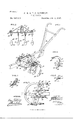
- Figure 1 is a perspective view of the im-.
- Fig. 2 is a transverse section through the beam and through the shanks connected therewith.
- Fig. 3 is a bottom plan view of a portion of the beam and the equalizing crossbars, showing the latter as having a diagonal position on the beam.
- Fig. 4 is a vertical section through the foot of a shank or stock and a vertical section through a blade and the attaching medium for the blade.
- Fig. 5 6c is a detail perspective view of one of the shanks or stocks and blade attached thereto, and Fig. 6 is a horizontal section taken substantially on the line 6 6 of Fig. 5.
- the beam A may be of any approved construction, and the ordinary handles B are secured to the same.
- two equalizing cross-bars 10 and 11 are placed in parallel order at the bottom portion of the beam, being pivotally attached thereto at their centers by bolts designated, respectively, as 10 and 11*.
- Two parallel trussbraces 12 and 13 are employed, one in connection with each of the equalizing cross-bars. These braces extend from the ends of the cross-bars upward over the top of the beam, being pivoted to the beam by the aforesaid bolts 10 and 11, each carrying a nut 14 at either the top or the bottom or at both ends.
- Links 15 connect the ends of the equalizing 8o cross-bars, as shown in Figs.
- the segmental or horizontally-arched bar 16 extends in a forwardly direction and moves between a-guide 18 and the bottom of the beam A, as illustrated in
- the shanks or stocks 19 are of peculiar construction, their forward ends 19 being twisted so as "to stand horizontally or laterally, and thereby the forward ends of the shanks or stocks may be brought squarely and firmly against the under face of the forward equalizing cross-bar 10, being attached thereto by the end bolts 17 and corresponding intermediate bolts 17
- the attachment be tween the shanks or stocks 19 and the rear equalizing cross-bar 11 is of a peculiar nature
- clip-bolts 20 are loosely passed through the rear equalizlng-bar, each clip-bolt terminatingat its lower end in a hook which passes around a portion of the shank of a stock 19, and while the clip bolts are free to turn in the rear equalizing cross-bar the shanks are held in proper relation to said bar by means of nuts 21, loeated at the upper ends of the said clip-bolts, thereby imparting to the shanks or stocks a sw1vel connection with the rear equalizing cross-bars.
- the clip-bolts 20 are also employed for connecting the ends of the rear equalizing cross-bars with the links and the truss-braces 13.
- the lower ends of the shanks or stocks 19 are preferably slightly enlarged, and the forward face of the lower end of each shank or stock is adapted to receive a blade of suitable construction.
- lVhen'a turn blade or share 26 is employed, or any blade or share that is to be given an lnclination is to be used, a shoe 22 is employed which is more or less thick at its outer side edge and quite thin at its inner side edge.
- Each shoe is thus given an inclined rear and forward face and each shoe is provided with a lug 23 at each side, which lugs engage with the side faces of the shank or stock to which the shoe 1s to be applied, and, furthermore, each shoe on its upper face is provided with a forwardly-extending rib 25 at its upper edge.
- the blade or share 26 is placed against the forward inclined face of the shoe, the upper rib 25 thereof extending over the top of the blade or share,as shown in Figs.
- lug 29 is formed, engaging with the outer side face of the shoe in connection with which the blade or share is employed. This lug 29 serves to preserve the rigidity of the blade or .share on the shank or stock.
Landscapes
- Life Sciences & Earth Sciences (AREA)
- Zoology (AREA)
- Engineering & Computer Science (AREA)
- Mechanical Engineering (AREA)
- Soil Sciences (AREA)
- Environmental Sciences (AREA)
- Footwear And Its Accessory, Manufacturing Method And Apparatuses (AREA)
Description
(No Model.)
P. 8: T. O. BORNMAN.
GULTIVATOR.
Patented Feb. 8, 1898.
WITNESSES 1 A TTORN E co. Pump-Lima. WASHINGTON, D. c.
UNITED STATES PATENT :OFFICE.
FREDRIOK HUFF BORNMAN AND THOMAS OOLLINSWORTH BORNMAN, OF
SUMMIT, MISSISSIPPI.
' CU LTIVATO R.
SPECIFICATION forming part of Letters Patent No. 598,849, dated February 8, 1898. Application filedJuly9,.189'7. Serial No. 644.008. woman.)
T0 at whom it may concern:
Be it known that We, FREDRIOK HUFF BORN- MAN and THOMAS OoLLINsWoRTH BORNMAN, of Summit, in the county of Pike and State of Mississippi, have invented a new and useful Improvement in Cultivators, of which the following is a full,clear,and exact description.
Our invention relates to an improvement in cultivators or side harrows; and the object of the invention is to provide a means whereby the angle, pitch, and spaces or distances of all the blades can be simultanously adjusted and in a manner tosecure complete arrangement and exactness in relative position, no matter to what extent the adjustment is carried, it being possible to retain the equalizing cross-bars, to which the shanks of the blades are attached, transversely to the beam or at any desired angle to the same, it being also possible to effect an adjustment of the blades in a speedy and convenient manner.
Another object of the invention'is to so construct the implement that a maximum of strength and rigidity will be obtained, combined with lightness.
Another object of the invention is to provide a means whereby any form of blade, whether it be a turning-plow orahalf-shovel, may be expeditiously and conveniently secured t0 the shanks or stocks and given any inclination necessary, the attachment .of the blades to the shanks or stocks being effected through the medium of a shoe and a single fastening-bolt.
Another object of the invention is to so effect the'attachment between a shank and a blade that'there will be absolute rigidity and the absence of a tendency toward turning on the part of the blade.
The invention consists in the novel construction and combination of the several .parts, as will be hereinafter fully set forth, and pointed out in the claims.
Reference is to be had to the accompanying drawings, forming a part of this specification, in which similar characters of reference indicate corresponding parts in all the figures.
Figure 1 is a perspective view of the im-.
proved implement, showing the equalizing cross-bars to which the blade shanks or stocks are applied as at a right angle to the beam.
Figs. 1 and 3.
Fig. 2 is a transverse section through the beam and through the shanks connected therewith. Fig. 3 is a bottom plan view of a portion of the beam and the equalizing crossbars, showing the latter as having a diagonal position on the beam. Fig. 4 is a vertical section through the foot of a shank or stock and a vertical section through a blade and the attaching medium for the blade. Fig. 5 6c is a detail perspective view of one of the shanks or stocks and blade attached thereto, and Fig. 6 is a horizontal section taken substantially on the line 6 6 of Fig. 5.
The beam A may be of any approved construction, and the ordinary handles B are secured to the same. In connection with the beam two equalizing cross-bars 10 and 11 are placed in parallel order at the bottom portion of the beam, being pivotally attached thereto at their centers by bolts designated, respectively, as 10 and 11*. Two parallel trussbraces 12 and 13 are employed, one in connection with each of the equalizing cross-bars. These braces extend from the ends of the cross-bars upward over the top of the beam, being pivoted to the beam by the aforesaid bolts 10 and 11, each carrying a nut 14 at either the top or the bottom or at both ends. Links 15 connect the ends of the equalizing 8o cross-bars, as shown in Figs. 1, 2, and 3, and at the ends of the forward equalizing crossbar 10 the extremities of a segmental bar 16 are pivotally attached through the medium of bolts 17, which pass through the forward equalizing-bar, through the forward ends of the links 15, and the extremities of the forward truss-bar 12. The segmental or horizontally-arched bar 16 extends in a forwardly direction and moves between a-guide 18 and the bottom of the beam A, as illustrated in The shanks or stocks 19 are of peculiar construction, their forward ends 19 being twisted so as "to stand horizontally or laterally, and thereby the forward ends of the shanks or stocks may be brought squarely and firmly against the under face of the forward equalizing cross-bar 10, being attached thereto by the end bolts 17 and corresponding intermediate bolts 17 The attachment be tween the shanks or stocks 19 and the rear equalizing cross-bar 11 is of a peculiar nature,
IOO
the attachment being shown best in Fig. 2, in which it will be observed that clip-bolts 20 are loosely passed through the rear equalizlng-bar, each clip-bolt terminatingat its lower end in a hook which passes around a portion of the shank of a stock 19, and while the clip bolts are free to turn in the rear equalizing cross-bar the shanks are held in proper relation to said bar by means of nuts 21, loeated at the upper ends of the said clip-bolts, thereby imparting to the shanks or stocks a sw1vel connection with the rear equalizing cross-bars. The clip-bolts 20 are also employed for connecting the ends of the rear equalizing cross-bars with the links and the truss-braces 13. The lower ends of the shanks or stocks 19 are preferably slightly enlarged, and the forward face of the lower end of each shank or stock is adapted to receive a blade of suitable construction.
lVhen'a turn blade or share 26 is employed, or any blade or share that is to be given an lnclination is to be used, a shoe 22 is employed which is more or less thick at its outer side edge and quite thin at its inner side edge. Each shoe is thus given an inclined rear and forward face and each shoe is provided with a lug 23 at each side, which lugs engage with the side faces of the shank or stock to which the shoe 1s to be applied, and, furthermore, each shoe on its upper face is provided with a forwardly-extending rib 25 at its upper edge. The blade or share 26 is placed against the forward inclined face of the shoe, the upper rib 25 thereof extending over the top of the blade or share,as shown in Figs. 4, 5, and 6, and a single bolt 28, provided with a suitable nut, is passed through the share or blade and through the shoe and lower portion of the shank or stock carrying the blade, as illustrated particularly 1n Fig. 4. Thus it will be observed that although only one bolt need be manipulated to remove or attach a share the share when attached will be effectually prevented from havlng lateral or vertical movement and may be given any desiredinclination. Furthermore, the shoe may be inclined to a greater or less extent in a transverse direction, or its front or its back face, or both, may be straight.
It is obvious that by turning the equalizing cross-bars on their pivots all of the shanks or stocks will be simultaneously moved and the distance between them will be accurately preserved. In this manner the blades may be held at a right angle to the beam or may be placed diagonally to a greater or to a less extent. It will be observed that the swivel connection between the rear equalizing-bar and the shanks or stocks and the pivoted connection between said shanks or stocks and the forward cross-bar positively admits of the adjustment of the blades above set forth.
At the outer side face of the blade or share 26 a lug 29 is formed, engaging with the outer side face of the shoe in connection with which the blade or share is employed. This lug 29 serves to preserve the rigidity of the blade or .share on the shank or stock.
Having thus described our invention, we claim as new and desire to secure by Letters Patent- 1. The combination with a beam, of equalizing cross-bars pivoted to the under side of the beam, truss-bars pivoted to equalizingbars near the ends, the said truss-bars being extended over the beam and pivoted on the bolts passing through the equalizing-bars and the beam, a curved bar connecting at its ends with the forward equalizing-bar, a locking device for said curved bar and share-stocks having connection with the eqaalizing-bars.
2. The combination, with a shank or stock, of a shoe having side lugs arranged for engagement with the side faces of the shank or stock and an upper rib on its outer face, a share engaging with the outer face of the shoe, the rib of the shoe engaging the upper end of the share, and a bolt connecting the shoe, the stock or shank and the share, for the purpose set forth.
3. The combination, with a stock or shank, of a shoe having its front and rear faces transversely inclined, the said shoe being provided with side lugs for engagement with the side faces of the shank, and a rib extending beyond its front face at the top, a share or blade placed in engagement with the forward inclined face of the shoe, the upper portion of the shank or blade being in contact with the upper rib of the shoe, and a bolt passing through the said blade or share, through the shoe and through the stock or shank, for the purpose described.
FREDR-ICK HUFF BORNMAN. THOMAS OOLLINSWOR'IH BORNMAN.
WVitnesses:
E. S. ATKINSON, W. B. MIXON.
Publications (1)
| Publication Number | Publication Date |
|---|---|
| US598849A true US598849A (en) | 1898-02-08 |
Family
ID=2667491
Family Applications (1)
| Application Number | Title | Priority Date | Filing Date |
|---|---|---|---|
| US598849D Expired - Lifetime US598849A (en) | Cultivator |
Country Status (1)
| Country | Link |
|---|---|
| US (1) | US598849A (en) |
-
0
- US US598849D patent/US598849A/en not_active Expired - Lifetime
Similar Documents
| Publication | Publication Date | Title |
|---|---|---|
| US598849A (en) | Cultivator | |
| US344296A (en) | Geoege welty | |
| US796942A (en) | Cultivator attachment. | |
| US494985A (en) | Cultivator | |
| US980586A (en) | Combined cultivator, harrow, and rake. | |
| US339835A (en) | baelbt | |
| US361853A (en) | Harrow | |
| US462533A (en) | Walking and riding cultivator | |
| US368288A (en) | Harrow | |
| US466383A (en) | Cultivator | |
| US392992A (en) | John e | |
| US703803A (en) | Plow. | |
| US205889A (en) | Improvement in cultivators | |
| US107037A (en) | Improvement in plows | |
| US527978A (en) | Harrow | |
| US133212A (en) | Improvement in harrows | |
| US368871A (en) | Double-shovel plow | |
| US338844A (en) | Thomas eli jones | |
| US389259A (en) | Plow and cultivator | |
| US488425A (en) | Harrow | |
| US265765A (en) | Cultivator | |
| US371355A (en) | Cultivator | |
| US302859A (en) | James w | |
| US558469A (en) | Harrow-tooth | |
| US308490A (en) | Thomas edwards gbegg |