US5966132A - Three-dimensional image synthesis which represents images differently in multiple three dimensional spaces - Google Patents
Three-dimensional image synthesis which represents images differently in multiple three dimensional spaces Download PDFInfo
- Publication number
- US5966132A US5966132A US08/596,236 US59623696A US5966132A US 5966132 A US5966132 A US 5966132A US 59623696 A US59623696 A US 59623696A US 5966132 A US5966132 A US 5966132A
- Authority
- US
- United States
- Prior art keywords
- virtual
- display objects
- image
- texture
- space
- Prior art date
- Legal status (The legal status is an assumption and is not a legal conclusion. Google has not performed a legal analysis and makes no representation as to the accuracy of the status listed.)
- Expired - Lifetime
Links
Images


Classifications
-
- A—HUMAN NECESSITIES
- A63—SPORTS; GAMES; AMUSEMENTS
- A63F—CARD, BOARD, OR ROULETTE GAMES; INDOOR GAMES USING SMALL MOVING PLAYING BODIES; VIDEO GAMES; GAMES NOT OTHERWISE PROVIDED FOR
- A63F13/00—Video games, i.e. games using an electronically generated display having two or more dimensions
- A63F13/50—Controlling the output signals based on the game progress
- A63F13/52—Controlling the output signals based on the game progress involving aspects of the displayed game scene
-
- A—HUMAN NECESSITIES
- A63—SPORTS; GAMES; AMUSEMENTS
- A63F—CARD, BOARD, OR ROULETTE GAMES; INDOOR GAMES USING SMALL MOVING PLAYING BODIES; VIDEO GAMES; GAMES NOT OTHERWISE PROVIDED FOR
- A63F13/00—Video games, i.e. games using an electronically generated display having two or more dimensions
- A63F13/20—Input arrangements for video game devices
- A63F13/24—Constructional details thereof, e.g. game controllers with detachable joystick handles
- A63F13/245—Constructional details thereof, e.g. game controllers with detachable joystick handles specially adapted to a particular type of game, e.g. steering wheels
-
- A—HUMAN NECESSITIES
- A63—SPORTS; GAMES; AMUSEMENTS
- A63F—CARD, BOARD, OR ROULETTE GAMES; INDOOR GAMES USING SMALL MOVING PLAYING BODIES; VIDEO GAMES; GAMES NOT OTHERWISE PROVIDED FOR
- A63F13/00—Video games, i.e. games using an electronically generated display having two or more dimensions
- A63F13/55—Controlling game characters or game objects based on the game progress
- A63F13/57—Simulating properties, behaviour or motion of objects in the game world, e.g. computing tyre load in a car race game
-
- A—HUMAN NECESSITIES
- A63—SPORTS; GAMES; AMUSEMENTS
- A63F—CARD, BOARD, OR ROULETTE GAMES; INDOOR GAMES USING SMALL MOVING PLAYING BODIES; VIDEO GAMES; GAMES NOT OTHERWISE PROVIDED FOR
- A63F13/00—Video games, i.e. games using an electronically generated display having two or more dimensions
- A63F13/80—Special adaptations for executing a specific game genre or game mode
- A63F13/803—Driving vehicles or craft, e.g. cars, airplanes, ships, robots or tanks
-
- G—PHYSICS
- G06—COMPUTING OR CALCULATING; COUNTING
- G06T—IMAGE DATA PROCESSING OR GENERATION, IN GENERAL
- G06T15/00—3D [Three Dimensional] image rendering
- G06T15/10—Geometric effects
- G06T15/20—Perspective computation
-
- G—PHYSICS
- G09—EDUCATION; CRYPTOGRAPHY; DISPLAY; ADVERTISING; SEALS
- G09G—ARRANGEMENTS OR CIRCUITS FOR CONTROL OF INDICATING DEVICES USING STATIC MEANS TO PRESENT VARIABLE INFORMATION
- G09G5/00—Control arrangements or circuits for visual indicators common to cathode-ray tube indicators and other visual indicators
- G09G5/42—Control arrangements or circuits for visual indicators common to cathode-ray tube indicators and other visual indicators characterised by the display of patterns using a display memory without fixed position correspondence between the display memory contents and the display position on the screen
-
- A—HUMAN NECESSITIES
- A63—SPORTS; GAMES; AMUSEMENTS
- A63F—CARD, BOARD, OR ROULETTE GAMES; INDOOR GAMES USING SMALL MOVING PLAYING BODIES; VIDEO GAMES; GAMES NOT OTHERWISE PROVIDED FOR
- A63F13/00—Video games, i.e. games using an electronically generated display having two or more dimensions
- A63F13/50—Controlling the output signals based on the game progress
- A63F13/52—Controlling the output signals based on the game progress involving aspects of the displayed game scene
- A63F13/525—Changing parameters of virtual cameras
- A63F13/5252—Changing parameters of virtual cameras using two or more virtual cameras concurrently or sequentially, e.g. automatically switching between fixed virtual cameras when a character changes room or displaying a rear-mirror view in a car-driving game
-
- A—HUMAN NECESSITIES
- A63—SPORTS; GAMES; AMUSEMENTS
- A63F—CARD, BOARD, OR ROULETTE GAMES; INDOOR GAMES USING SMALL MOVING PLAYING BODIES; VIDEO GAMES; GAMES NOT OTHERWISE PROVIDED FOR
- A63F2300/00—Features of games using an electronically generated display having two or more dimensions, e.g. on a television screen, showing representations related to the game
- A63F2300/10—Features of games using an electronically generated display having two or more dimensions, e.g. on a television screen, showing representations related to the game characterized by input arrangements for converting player-generated signals into game device control signals
- A63F2300/1062—Features of games using an electronically generated display having two or more dimensions, e.g. on a television screen, showing representations related to the game characterized by input arrangements for converting player-generated signals into game device control signals being specially adapted to a type of game, e.g. steering wheel
-
- A—HUMAN NECESSITIES
- A63—SPORTS; GAMES; AMUSEMENTS
- A63F—CARD, BOARD, OR ROULETTE GAMES; INDOOR GAMES USING SMALL MOVING PLAYING BODIES; VIDEO GAMES; GAMES NOT OTHERWISE PROVIDED FOR
- A63F2300/00—Features of games using an electronically generated display having two or more dimensions, e.g. on a television screen, showing representations related to the game
- A63F2300/60—Methods for processing data by generating or executing the game program
- A63F2300/64—Methods for processing data by generating or executing the game program for computing dynamical parameters of game objects, e.g. motion determination or computation of frictional forces for a virtual car
-
- A—HUMAN NECESSITIES
- A63—SPORTS; GAMES; AMUSEMENTS
- A63F—CARD, BOARD, OR ROULETTE GAMES; INDOOR GAMES USING SMALL MOVING PLAYING BODIES; VIDEO GAMES; GAMES NOT OTHERWISE PROVIDED FOR
- A63F2300/00—Features of games using an electronically generated display having two or more dimensions, e.g. on a television screen, showing representations related to the game
- A63F2300/60—Methods for processing data by generating or executing the game program
- A63F2300/66—Methods for processing data by generating or executing the game program for rendering three dimensional images
- A63F2300/6615—Methods for processing data by generating or executing the game program for rendering three dimensional images using models with different levels of detail [LOD]
-
- A—HUMAN NECESSITIES
- A63—SPORTS; GAMES; AMUSEMENTS
- A63F—CARD, BOARD, OR ROULETTE GAMES; INDOOR GAMES USING SMALL MOVING PLAYING BODIES; VIDEO GAMES; GAMES NOT OTHERWISE PROVIDED FOR
- A63F2300/00—Features of games using an electronically generated display having two or more dimensions, e.g. on a television screen, showing representations related to the game
- A63F2300/60—Methods for processing data by generating or executing the game program
- A63F2300/66—Methods for processing data by generating or executing the game program for rendering three dimensional images
- A63F2300/6661—Methods for processing data by generating or executing the game program for rendering three dimensional images for changing the position of the virtual camera
- A63F2300/6669—Methods for processing data by generating or executing the game program for rendering three dimensional images for changing the position of the virtual camera using a plurality of virtual cameras concurrently or sequentially, e.g. automatically switching between fixed virtual cameras when a character change rooms
-
- A—HUMAN NECESSITIES
- A63—SPORTS; GAMES; AMUSEMENTS
- A63F—CARD, BOARD, OR ROULETTE GAMES; INDOOR GAMES USING SMALL MOVING PLAYING BODIES; VIDEO GAMES; GAMES NOT OTHERWISE PROVIDED FOR
- A63F2300/00—Features of games using an electronically generated display having two or more dimensions, e.g. on a television screen, showing representations related to the game
- A63F2300/80—Features of games using an electronically generated display having two or more dimensions, e.g. on a television screen, showing representations related to the game specially adapted for executing a specific type of game
- A63F2300/8017—Driving on land or water; Flying
Definitions
- This invention relates to a three-dimensional(3D) simulator apparatus and an image synthesis method that enable the simulation of a virtual 3D space.
- 3D simulator apparatus that are used in applications such as 3D games or piloting simulators for aircraft or other moving bodies are known in the art.
- image information relating to a 3D object 300 shown in FIG. 25A his previously stored within the apparatus.
- the 3D object 300 depicts an element such as part of scenery that can be seen by a player 302 as if through a screen 306.
- the image information for the 3D object 300 that depicts this scenery element is displayed as a pseudo-3D image 308 on the screen 306, by perspective projection conversion on the screen 306.
- the player 302 specifies operations such as rotation or translation through a control Panel 304, and this apparatus performs predetermined 3D computation processing on the basis of the resultant operating signals.
- computations are first performed to determine whether a change has occurred, such as a change in the viewpoint position or direction of gaze of the player 302 or a change in the position or orientation of a moving body in which the player 302 is sitting, as specified by these operating signals. Computations are then performed to determine how the image of the 3D object 300 can be seen on the screen 306, in accordance with this change such as a change in viewpoint position or direction of gaze. The above computations are performed in real time, following the actions of the player 302.
- FIG. 25B An example of a display screen formed by a 3D simulator apparatus as described above is shown in FIG. 25B.
- the realism of the game or simulation can be enhanced by forming a sub-screen depicting an element such as a rear-view mirror or a side mirror on a display screen (main screen) as shown in FIG. 25B.
- a pseudo-3D image with a degree of realism that is similar to that of the main screen is displayed on the sub-screen, such as the rear-view mirror.
- This invention was devised in order to solve the above technical problems and has as its objective the provision of a 3D simulator apparatus and an image synthesis method that can not only create an extremely realistic sub-screen on a main screen, but also ensures that the formation of this sub-screen hardly affects the image synthesis processing for the main screen.
- a three-dimensional-(3D) simulator apparatus relating to a first aspect of this invention comprises: a virtual three-dimensional(3D) space computation means for computing and forming a virtual three-dimensional(3D) space by setting either position or position and orientation of a plurality of display objects configuring the virtual 3D space; and
- an image synthesis means for synthesizing a field-of-view image as seen from any desired viewpoint within the virtual 3D space, on the basis of computation results from the virtual 3D space computation means;
- the virtual 3D space computation means comprises:
- the image synthesis means comprises:
- a plurality of virtual 3D spaces are formed in which the position or position and orientation of display objects is the same but the number of polygons configuring each of these display objects is different, such as first and second virtual 3D spaces,
- a display object having a smaller number of polygons than a display object in the first virtual 3D space is placed in the second virtual 3D space at the same position and orientation (the same position, if only a position is specified for the display object) as those of the display object in the first virtual 3D space.
- a field-of-view image in the first virtual 3D space wherein the number of polygons for each display object is larger is displayed on the main screen
- a field-of-view image in the second virtual 3D space wherein the number of polygons for each display object is smaller is displayed on the sub-screen.
- an extremely realistic image such as that as seen through a rear-view mirror, a side mirror, or from above the moving body can be displayed on the main screen. Note that computations for inverseing this field-of-view image horizontally will be required if the sub-screen is used to show a rear-view or side mirror, to obtain a rearward-facing field-of-view image as seen by the operator.
- a second aspect of this invention further comprises:
- texture computation means for performing computations for implementing texture with respect to polygons configuring the display objects
- texture information storage means for storing information on the texture to be implemented by the texture computation means;
- the texture computation means comprises:
- texture information storage means for using texture information stored in the texture information storage means in common, for at least a part of the display objects in different virtual 3D spaces that have either the same position or the same position and orientation.
- a 3D simulator apparatus in accordance with a third aspect of this invention comprises:
- virtual three-dimensional(3D) space computation means for computing and forming a virtual three-dimensional(3D) space by setting display object information that comprises either an object number and position information or an object number and position and orientation information for each of a plurality of display objects configuring the virtual 3D space;
- image information storage means for storing image information for an object specified by the object number
- image synthesis means for synthesizing a field-of-view image as seen from any desired viewpoint within the virtual 3D space, on the basis of the display object information and the image information read out from the image information storage means according to the object number;
- the virtual 3D space computation means comprises:
- the image information storage means stores the image information which has different numbers of polygons configuring each object specified by the different object numbers;
- the image synthesis means comprises:
- a plurality of groups of display object information having the same position information but different object numbers is formed, such as first and second display object information.
- Image information is formed for an object specified by an object number in the first display object information, in such a manner that, for example, the number of polygons is larger.
- image information is formed for an object specified by an object number in the second display object information, in such a manner that, for example, the number of polygons is smaller.
- a field-of-view image to be displayed on the main screen is synthesized on the basis of the image information read out by the object number in the first display object information and a field-of-view image to be displayed on the sub-screen is synthesized on the basis of the image information read out by the object number in the second display object information.
- the number of polygons required for forming the sub-screen can be reduced without greatly deteriorating the quality of the image displayed on the main screen, making it possible to support real-time image processing, Moreover, since a field-of-view image from any desired viewpoint in the virtual 3D space is synthesized by using display object information and object image information in the same manner for the formation of both the sub-screen and the main screen, the realism of the image displayed on the sub-screen can be enhanced.
- the image information storage means stores the image information for a plurality of objects with different numbers of polygons
- the image synthesis means comprises:
- the selection range of the objects for synthesizing the field-of-view image on the main screen is a selection range comprising more objects with larger numbers of polygons than the selection range of the objects for synthesizing the field-of-view image for the sub-screen.
- image information for a plurality of objects that have position and other information in common but different numbers of polygons is provided, such as image information for first, second, and third objects.
- first object has the largest number of polygons
- third object has the smallest number of polygons.
- the field-of-view image for the sub-screen is synthesized, only the second and third objects, for example, are selected from the first, second, and third objects, so that this field-of-view image is synthesized on the basis of the image information for the second and third objects.
- This makes it possible to provide processing whereby far-distance, middle-distance, and near-distance objects are used on the main screen depending on the distance therefrom, for example, and middle-distance and near-distance objects alone are used on the sub-screen depending on the distance therefrom.
- the number of polygons required for forming the sub-screen can be reduced overall to less than the number of polygons required for forming the main screen.
- a realistic image can be displayed on the sub-screen without greatly affecting the image synthesis processing for the main screen.
- the virtual 3D space computation means comprises:
- the virtual 3D space computation means comprises:
- display on the sub-screen is omitted for some of the display objects that are displayed on the main screen.
- objects such as buildings displayed on the main screen can be omitted from the sub-screen, for example. Since the size of the sub-screen is normally less than that of the main screen, the player is not likely to notice when some objects are omitted in this manner. This omission of the display of some objects from the sub-screen also makes it possible to further reduce the number of polygons required for forming the sub-screen.
- a sixth aspect of this invention further comprises means for dividing a map configuring a virtual 3D space into a predetermined number of segments and displaying the map by placing map objects in a segmented map;
- the number of segments of a map displayed on the main screen is greater than the number of segments of a map displayed on the sub-screen.
- This aspect of the invention makes it possible to display a map that is expressed in detail on the main screen, and also display a map that is expressed in a simplified manner on the sub-screen. As a result, the number of polygons required for forming the sub-screen can be reduced, and a realistic image can be displayed on the sub-screen without greatly affecting the image synthesis processing for the main screen.
- a seventh aspect of this invention further comprises texture computation means for performing computations for implementing texture with respect to polygons configuring objects;
- texture information storage means for storing information on the texture implemented by the texture computation means;
- the image information storage means stores vertex texture to coordinates for specifying texture information in the texture information storage means as part of the image information
- the texture computation means comprises:
- this aspect of the invention it is not necessary to provide separate texture information for the main screen and the sub-screen, so that the storage capacity required of the texture information storage means can be reduced. This makes it possible to design a less expensive apparatus. Moreover, since display objects for the sub-screen are also subjected to texture mapping by this aspect of the invention, the realism of the image displayed on the sub-screen can be enhanced so that it is similar to that of the main screen. Note that this aspect of the invention makes it possible to use vertex brightness information in common, in addition to vertex texture coordinates.
- FIG. 1 is a block diagram of an example of an embodiment in accordance with this invention.
- FIG. 2 is a schematic view of an example of the exterior of this 3D simulator apparatus
- FIG. 3 is a schematic view of an example of a virtual 3D space
- FIG. 4 is a schematic view of a game scene (pseudo-3D image) synthesized by this 3D simulator apparatus;
- FIG. 5 is a block diagram of an example of a virtual 3D space computation section
- FIG. 6 is a schematic diagram used for illustrating display object information that is stored in the display object information storage section
- FIG. 7 is a schematic view used for illustrating display object information that is set for each object
- FIGS. 8A and 8B are schematic diagrams used for illustrating a plurality of groups of display object information with the same position and orientation information but different object numbers;
- FIG. 9 shows a plurality of types of racing car object having different numbers of polygons
- FIG. 10 shows an example of a track object configured of a large number of polygons
- FIG. 11 shows an example of a track object configured of a small number of polygons
- FIG. 12 shows a map divided into a plurality of map blocks
- FIG. 13 shows the concept of map objects to be placed in map blocks
- FIG. 14 shows a plurality of types of map block with different numbers of segments
- FIG. 15 is a block diagram of an example of an image supply section
- FIG. 16 is a schematic view used for illustrating the 3D computation processing performed by this embodiment.
- FIGS. 17A and 17B show an example of the data format formed by the data formatting section
- FIG. 18 is a block diagram of an example of an image synthesis section
- FIG. 19 is a schematic view used for illustrating a texture mapping method
- FIGS. 20(A) to 20(K) pictorially illustrate the texture mapping method of this embodiment
- FIGS. 21A and 21B pictorially illustrate the implementation of texture mapping on a racing car object
- FIG. 22 shows an example of a stored texture plane (texture space) formed on the texture information storage section
- FIGS. 23A and 23B show examples of map objects to be placed in the first and second virtual 3D spaces, and FIG. 23C shows an example of texture information mapped onto these map objects and a texture plane including this texture information;
- FIG. 24 is a schematic view used for illustrating another application example of the sub-screen.
- FIG. 25A is a schematic view used for illustrating the concept of the 3D simulator apparatus, and FIG. 25B shows an example of the screen formed by this 3D simulator apparatus.
- the 3D game enabled by this 3D simulator apparatus is a racing-car game in which a moving body, such as the player's racing car, runs along a track formed on a map, so that the player can compete against other racing cars operated by other players or computer cars operated by a computer.
- a moving body such as the player's racing car
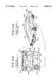
- FIG. 2 An example of the exterior of such a 3D simulator apparatus is shown in FIG. 2.
- the 3D simulator apparatus is configured in the same manner as the driver's seat of a real-life racing car, as shown in this figure.
- the player sits in a seat 18 and drives this imaginary racing car by operating controls such as a steering wheel 14, accelerator pedal 15, and shift lever 16 provided in a control section 12, while viewing a game scene (a pseudo-3D image of the surroundings as seen from the driver's seat of the racing car) that appears on a CRT (display) 10.
- controls such as a steering wheel 14, accelerator pedal 15, and shift lever 16 provided in a control section 12, while viewing a game scene (a pseudo-3D image of the surroundings as seen from the driver's seat of the racing car) that appears on a CRT (display) 10.
- FIG. 3 An example of a virtual 3D space formed by this 3D game is shown in FIG. 3.
- This figure shows how a track 20 that is formed in a three-dimensional fashion is laid out within the virtual 3D space of the 3D game.
- Various 3D objects such as buildings 60, a tunnel 62, mountain 64, cliffs 66, and walls 68 are also laid out around the periphery of this track 20.
- the player operates the racing car while viewing the CRT 10 on which is projected this track and other 3D objects.
- the player starts from a starting line 70, drives around the track 20 a predetermined number of times until he or she reaches a finishing line, and thus the player's ranking is determined.
- FIG. 4 An example of the game scene projected on the CRT 10 during this 3D game is shown in FIG. 4.
- a main screen 1 in FIG. 4 displays another racing car, such as another player's racing car 52, and the player can compete against the other player's racing car 52 while watching this main screen 1.
- elements such as a road surface 21 and tunnel walls 22 are also displayed on the main screen, in addition to the other player's racing car 52.
- a depiction of a rear-view mirror (sub-screen) 2 is also displayed onto the main screen 1, and the player can check whether a computer-operated car 54 is chasing from behind, by looking in this rear-view mirror 2.
- a road surface 23 and walls 24 are displayed on the rear-view mirror 2, in the same manner as on the main screen.
- An asphalt-like pattern is applied to the road surface 23 that is displayed on the rear-view mirror 2, similar to that projected on the road surface 21 in the main screen 1, and elements such as a center-line 26 are drawn thereon.
- the 3D game ensures that the image inversed in the rear-view mirror 2 is just as realistic as the main screen 1. Further details such as tail-lamps are drawn on the other player's racing car 52 on the main screen 1, as shown in FIG. 4, and the other player's racing car 52 itself is accurately drawn so that it appears to be close to the real thing.
- the computer-operated car 54 displayed on the rear-view mirror 2 is drawn in a more abbreviated form than the other player's racing car 52.
- a virtual 3D space for drawing the main screen 1 and a virtual 3D space for drawing the rear-view mirror are provided separately, as will be described later.
- the display area of the rear-view mirror 2 is smaller than that of the main screen 1, so it is possible to reduce the degree of detail of the display objects to a certain extent without the player noticing.
- the number of polygons configuring each of the display objects in the rear-view mirror 2 is reduced to less than the number of polygons configuring each of the display objects in the main screen 1. This makes it possible to reduce the total number of polygons that have to be subjected to computation processing, while preserving the feeling of realism to a certain extent, and is also effective in preventing problems such as the dropping of image data from the main screen 1.
- FIG. 1 A block diagram of an embodiment of the 3D simulator apparatus to which this invention is applied is shown in FIG. 1.
- This 3D simulator apparatus comprises a control section 12 to which the player inputs operating signals, a virtual 3D space computation section 100 that performs computations for setting a virtual 3D space according to a predetermined games program, an image synthesis section 200 that forms a pseudo-3D image as if seen from the viewpoint of the player, and the CRT (display) 10 that outputs this pseudo-3D image.
- control section 12 is connected to controls such as the steering wheel 14 and accelerator pedal 15 for driving the racing car, and operating signals are input thereby.
- the virtual 3D space computation section 100 performs computations to set either the position alone or the position and orientation of the plurality of display objects within the virtual 3D space shown in FIG. 3, such as the track 20, buildings 60, tunnel 62, mountain 64, cliffs 66, and walls 68, the player's own racing car, other players' racing cars, and computer-operated cars. These computations are based on factors such as operating signals from the control section 12 and map information that has previously been stored.
- the image synthesis section 200 performs computations to form a field-of-view image as seen from any desired viewpoint within the virtual 3D space, on the basis of the computation results from the virtual 3D space computation section 100.
- the thus formed field-of-view image is output by the CRT 10.
- first and second virtual 3D spaces are formed by the computations of the virtual 3D space computation section 100. These spaces have different numbers of polygons that configure display objects having the same position or position and orientation. In other words, two virtual 3D spaces are provided for the scene shown in FIG. 3. Note that there is a different number of polygons configuring the display objects in these two virtual 3D spaces, such that the first virtual 3D space is set to have a larger number of polygons in each display object.
- a field-of-view image of the first virtual 3D space is formed by the image synthesis section 200 as the image to be displayed on the main screen.
- a field-of-view image of the second virtual 3D space is formed as the image to be displayed on the sub-screen.
- a field-of-view image is formed from the first virtual 3D space as if seen by a forward-facing direction of gaze with the viewpoint position being at the position of the player's car.
- a field-of-view image is formed from the second virtual 3D space as if seen by a rearward-facing direction of gaze.
- the field-of-view image computed in the second virtual 3D space is also subjected to a horizontal(right-and-left) inversion, before being displayed on the rear-view mirror 2.
- FIG. 5 A block diagram of an example of the virtual 3D space computation section 100 is shown in FIG. 5
- FIG. 15 A block diagram of an example of an image supply section 210 within the image synthesis section 200 is shown in FIG. 15, and a block diagram of an example of an image forming section 228 therein is shown in FIG. 18.
- the virtual 3D space computation section 100 comprises a processing section 102, a virtual 3D space setting section 104, a movement information computation section 106, and a display object information storage section (object information storage section) 108.
- control of the entire 3D simulator apparatus is performed by the processing section 102.
- a predetermined games program is stored within a memory section that is provided within the processing section 102.
- the virtual 3D space computation section 100 is designed to compute the setting of virtual 3D spaces in accordance with this games program and operating signals from the control section 12.
- Movement information for the racing car is computed by the movement information computation section 106 in accordance with operating signals from the control section 12 and instructions from the processing section 102.
- Position and orientation information for each display object that configures the virtual 3D space is stored in the display object information storage section 108, together with an object number referring to the object that is to be displayed at that position (this stored position and orientation information and the object number is hereinafter called display object information (object information)).
- object information An example of the display object information stored in the display object information storage section 108 is shown in FIG. 6.
- the relationship between position and orientation information (Xm, Ym, Zm, ⁇ m, ⁇ m, ⁇ m) included within this display object information and an absolute coordinate system (Xw, Yw, Zw) is shown in FIG. 7.
- an object is a moving body object depicting a racing car or a map object depicting an immobile thing such as a track, and each object is expressed as a collection of polygons, as shown in FIG. 7.
- the display object information stored in the display object information storage section 108 is read out by the virtual 3D space setting section 104. At that point, display object information for the frame before the current frame is stored-in the display object information storage section 108. Display object information (position and orientation information) for that particular frame is obtained by the virtual 3D space setting section 104 on the basis of the thus read-out display object information and movement information computed by the movement information computation section 106.
- the above described updating of the display object information for each frame as the game progresses is done for display objects that are moving bodys such as racing cars; the display object information for the map normally remains constant.
- the map depicts features such as meteors in an outer-space game, it may be necessary to change more information such as orientation information as the game progresses. Some kinds of map may have position information but no orientation information.
- a map setting section 110 is provided in the virtual 3D space setting section 104 of FIG. 5 and the map setting is performed by this map setting section 110.
- the predetermined computation processing performed by the virtual 3D space setting section 104 takes the display object information of FIG. 6 and forms a plurality of groups of display object information wherein the position and orientation information is the same (or the position information is the same, if the display object information has no orientation information) but the object numbers are different. More specifically, the virtual 3D space setting section 104 reads out the display object information that is stored in the display object information storage section 108, as shown in FIG. 6, and forms a plurality of groups of display object information by changing only the object number. The thus formed plurality of groups of display object information is output to the image synthesis section 200.
- FIGS. 8A and 8B An example of the plurality of groups of display object information formed in this manner is shown in FIGS. 8A and 8B.
- the display object information shown in FIG. 8A is the same as that of FIG. 6.
- the display object information shown in FIG. 8B differs from that of FIG. 8A only in the object numbers of the display object information.
- an object OB0 of FIG. 8A and an object OBi+1 of FIG. 8B have the same position and orientation information (X0, Y0, Z0, ⁇ 0, ⁇ 0, ⁇ 0) but different object numbers.
- This formation of display object information with the same position and orientation information but different object numbers makes it possible to present racing cars 48A, 48B, and 48C that have different numbers of polygons, as shown in FIG. 9.
- the racing cars 48A, 48B, and 48C have the same position and orientation information but different object to numbers OBi, OBj, and OBk.
- Object image information (the number of polygons and other polygon information are expressed by this object image information) for the racing cars 48A, 48B, and 48C is stored in an object image information storage section 212 shown in FIG. 5, and this object image information can be read out therefrom by specifying an object number.
- each of the racing cars 48A, 48B, and 48C with different numbers of polygons as shown in FIG. 9 can be read out by specifying different object numbers.
- Each of these racing cars 48A, 48B, and 48C is placed with the same position and orientation in the first and second virtual 3D spaces.
- two virtual 3D spaces containing display objects that have different numbers of polygons can be implemented, by placing objects that have the same position and orientation, but different numbers of polygons, to configure the virtual 3D spaces.
- Track objects 30A and 30B (map objects) with different numbers of polygons are shown in FIGS. 10 and 11.
- the track object 30A is drawn in detail with a larger number of polygons, whereas the track object 30B is drawn more simply, with fewer polygons.
- the track 20 shown in FIG. 3 is configured of a series of such track objects.
- Two tracks are provided by this embodiment: one configured of track objects with a large number of polygons and another configured of track objects with a small number of polygons.
- a plurality of groups of display object information relating to the track can be formed by simply changing the object number within the display object information of FIG. 6.
- two virtual 3D spaces can be expressed by forming a plurality of groups of display object information that can be used to place objects that have different numbers of polygons but have the same position and orientation.
- a field-of-view image of the first virtual 3D space configured of objects with many polygons is displayed on the main screen, and a display image of the second virtual 3D space configured of objects with few polygons is displayed on the sub-screen. This makes it possible to reduce the number of polygons required for forming the sub-screen.
- a plurality of groups of display object information is output from the virtual 3D space computation section 100 to the image synthesis section 200, it is preferable that only display object information for objects that will be placed within a predetermined area specified by the player's view-point position and direction of gaze is output. For example, it is not necessary to perform image synthesis processing for moving body and map objects that are far from the viewpoint of the player and cannot be seen therefrom. Therefore, it is preferable that display object information for such objects is omitted from the output to the image synthesis section 200.
- the configuration is such that only display object information for objects that are within a fixed range infront of the player is output for objects to be displayed on the main screen. Similarly, only display object information for objects within a fixed range behind the player is output for objects to be displayed on the sub-screen. This makes it possible to reduce the amount of computations performed by the image synthesis section 200.
- the method described below could be used to further reduce the numbers of polygons required for forming the main screen and sub-screen.
- the racing cars 48A, 48B, and 48C shown in FIG. 9 could be used as racing cars to appear in the near distance, middle distance, and far distance within the first virtual 3D space.
- the near-distance racing car 48A is displayed on the main screen when the distance between the player's car and another racing car is short, but the middle-distance racing car 48B or far-distance racing car 48C is displayed thereon when the distance therebetween is greater. This makes it possible to reduce the number of polygons required for forming the main screen, without sacrificing any feeling of realism in the display image.
- the racing car 48B is used as a near-distance racing car and the racing car 48C is used as a far-distance racing car, depending on the distance from the player's car.
- the number of polygons required for forming the sub-screen can be even further reduced by using the near-distance and far-distance racing cars as appropriate in the sub-screen.
- a further method that could be used places the buildings 60 of FIG. 3 in the first virtual 3D space, but omits these buildings 60 from the second virtual 3D space. More specifically, none of the display object information shown in FIGS. 6 and 8 is formed for the buildings 60 in the second virtual 3D space. This makes it possible to further reduce the number of polygons required for rending the sub-screen.
- a still further method that could be used concerns the depiction of a map in which the map that forms the virtual 3D space is divided into a predetermined number of map blocks, as shown for example in FIG. 12, and map objects are places in these map blocks.
- a mountain 40a having a large number of polygons as shown for example in FIG. 13, is placed in the first virtual 3D space.
- mountains 40b and 40c having smaller numbers of polygons are placed in second and third virtual 3D spaces. This makes it possible to reduce the number of polygons necessary for forming the sub-screen.
- first, second, and third map blocks 31, 32, and 33 with different numbers of segments could be provided, as shown in FIG. 14.
- the first map blocks 31 are used as map segments for the first virtual 3D space.
- the second map blocks 32 or third map blocks 33 are used as map segments for the second virtual 3D space. If map objects are formed in such a manner that there are approximately the same number of polygons in each map object placed in each of these blocks, the total number of polygons required for configuring this map can be set to be less in the second virtual 3D space than in the first virtual 3D space. This makes it possible to reduce the number of polygons necessary for forming the sub-screen.
- This method of allocating map blocks with different numbers of segments is particularly effective for enabling most of the map of the virtual 3D space to be seen by the player, such as in a fighter-plane game or flight simulator.
- first, second, and third map blocks can be allocated within the first virtual 3D space and the second and third map blocks can be allocated within in the second virtual 3D space, depending on the distance between the player's own plane and each of the map segments, in a similar manner to the above described use of far-distance, middle-distance, and near-distance racing cars. This makes it possible to reduce the number of polygons in the main screen as well as in the sub-screen.
- the computations for dividing the map into a predetermined number of blocks and placing the map object therein, as described above, are performed by means such as the map setting section 110.
- the image supply section 210 comprises an object image information storage section 212, a processing section 215, a coordinate conversion section 218, a clipping processing section 220, a polygon data conversion section 224, and a sorting processing section 226, as shown in FIG. 15.
- the clipping processing section 220 further comprises a perspective projection conversion section 222.
- Various types of coordinate conversion processing and 3D computation processing are performed by the image supply section 210, in accordance with setting information for the virtual 3D space that is set by the virtual 3D space computation section 100.
- computations are performed for objects 300, 333, and 334 that depict elements such as a racing car and the track, to place the polygons that configure these objects in a virtual 3D space expressed in absolute coordinates (world coordinates) (XW, YW, ZW), as shown in FIG. 16.
- the coordinates of each of these objects are then converted into view coordinates (Xv, Yv, Zv) referenced to the viewpoint of the player 302.
- a process called clipping processing is then performed, followed by perspective projection conversion processing into screen coordinates (XS, YS).
- the data is converted into output format, and finally sorting processing is performed.
- image information for objects depicting elements such as the racing car and the track is written to the object image information storage section 212. Note, however, that this write is not necessary if the object image information storage section 212 is read-only memory (ROM).
- ROM read-only memory
- Viewpoint information that is common to all of the objects which is information such as the player's viewpoint, angle, and angle of visibility and monitor information, is updated every field (every 1/60 second, for example) and is transferred from the virtual 3D space computation section 100 through the processing section 215 to the coordinate conversion section 218.
- the various types of coordinate conversion are performed by the coordinate conversion section 218 on the basis of this data.
- Information such as the angle and size of the monitor is also transferred to the clipping processing section 220 as data for clipping processing.
- the thus transferred data is called frame data.
- Display object information which comprises position and orientation information and the object number of each object, is transferred from the virtual 3D space computation section 100 to the processing section 215.
- This object number is used as an address to read out image information for the corresponding object from the object image information storage section 212.
- the object number specifies a racing car, for example, image information for that racing car is read from the object image information storage section 212.
- the image information for each element such as a racing car is stored in the object image information storage section 212 as a collection of a plurality of polygons.
- a data formatting section 217 forms data that combines the object data and polygon data from the thus read-out data, then the processing section 215 sequentially transfers it to the coordinate conversion section 218.
- object data consists of position and orientation information for the object, together with associated data.
- Polygon data is image information for the polygons that configure each object, which consists of polygon vertex coordinates, vertex texture coordinates, vertex brightness information, and other associated data.
- This data is converted by the data formatting section 217 into the data format shown in FIGS. 17A and 17B.
- the coordinate conversion section 218 performs various types of coordinate conversion on the polygon data on the basis of object data consisting of player's viewpoint information transferred from the processing section 215 and racing car position and orientation information transferred from the processing section 215. In other words, the coordinate conversion section 218 rotates the polygon data within the local coordinate system, and transforms it into the world coordinates, and then into the viewpoint coordinates.
- the clipping processing section 220 performs clipping processing for polygon data that has been subjected to this coordinate conversion. This data is then subjected to perspective projection conversion into the screen coordinate system by the perspective projection conversion section 222 within the clipping processing section 220. Note that the same hardware can be used for this clipping processing and perspective projection conversion processing in this embodiment.
- the data for polygons that were changed by the clipping processing into polygonal shapes that are not four-sided is converted into data for four-sided polygons by the polygon data conversion section 224.
- the converted polygon data is output to the sorting processing section 226 of the next stage. More specifically, if a polygon has been changed into a triangular shape by the clipping processing, for example, conversion processing is performed to change that three-sided polygon into a pseudo-four-sided polygon. If the vertices of the original three-sided polygon are numbered 1, 2, and 3, the vertices of the four-sided polygon after the conversion are allocated vertex numbers. 1, 2, 3, and 1 of the original polygon.
- the data is converted into four-sided polygon data by specifying information such as the vertex coordinates, vertex texture coordinates, and vertex brightness information of the original polygon according to the thus allocated vertex numbers.
- conversion processing is performed to divide that polygon into a four-sided polygon and a pseudo-four-sided polygon (similar to the above described way in which a three-sided polygon is converted into a pseudo-four-sided polygon).
- the vertices of the resultant two four-sided polygons are allocated vertex numbers 1, 2, 3, and 4 and 1, 4, 5, and 1 of the original polygon.
- the data is converted into four-sided polygon data by specifying information such as the vertex coordinates, vertex texture coordinates, and vertex brightness information of the original polygon according to the thus allocated vertex numbers.
- a polygon has been changed into a six-sided shape by the clipping processing, it is divided into two four-sided polygons in a similar way to that described above.
- any polygon that is reversed into a back face polygon by horizontal(right-and-left) inversion processing of the image during image forming for the rear-view mirror in accordance with this embodiment is subjected to conversion processing by the polygon data conversion section 224 to change it into a frontface polygon.
- the allocation of vertex numbers for the converted polygon is 1, 4, 3, and 2, and details such as the vertex coordinates of the original polygon are specified by the thus substituted vertex numbers. This means that it is possible for a polygon that was reversed by the horizontal inversion processing to be output.
- a polygon that has been turned into a five-sided polygon by the clipping processing described above is subjected to horizontal inversion processing, it is divided into a four-sided polygon and a pseudo-four-sided polygon, and the vertex numbers allocated to these four-sided polygons are made to be 1, 4, 3, and 2 and 1, 5, 4, and 1, respectively.
- main-screen data and subsidiary-screen data as shown in FIG. 17A is formed by the data formatting section 217 and this data is transferred to other sections such as the coordinate conversion section 218 as data to be processed within each frame.
- the main-screen data starts with frame data, followed by data for objects 1A, 2A, 3A, and so on in sequence.
- data relating to all the objects to be displayed on the main screen in that frame is arrayed in sequence.
- Polygon data for all of the polygons configuring a particular object is arrayed after the object data for object 1A, for example.
- This polygon data comprises details of the polygons, such as vertex coordinates information, in the format shown in FIG. 17B.
- polygon data for all of the polygons configuring object 2A is arrayed after the object data for that object.
- the sub-screen data is formed in exactly the same format as that of the main-screen data. Note, however, that objects 1A and 1B have the same object placement position and orientation, but different numbers of groups of polygon data linked to the object data. Objects 2A and 2B differ in the same manner.
- This embodiment makes it possible to have different numbers of polygons for objects displayed by the main screen and the sub-screen, by having the data formatting section 217 create data in the above format. Further differences, such as a difference in viewpoint position or orientation, can be achieved between the main-screen and sub-screen data. In such a case, the contents of the frame data positioned at the start of each of the main-screen data and the sub-screen data could be made different.
- a rear-view mirror can be formed on top of the main screen which displays a forward image. Note, however, that it is necessary in such a case to subject the image to horizontal inversion before displaying it, but this horizontal inversion processing can be performed by the polygon data conversion section 224 of this embodiment, as described previously.
- the image forming section 228 is designed to compute image information within polygons, based on vertex image information given for each vertex of these polygons, then output this information to the CRT 10. It comprises a processor section (texture computation means) 230, a texture information storage section 242, and a palette and mixer circuit 244, as shown in FIG. 18.
- image synthesis by methods called texture mapping and Gouraud shading is performed in order to form a higher-quality image more efficiently.
- texture mapping and Gouraud shading is performed in order to form a higher-quality image more efficiently.
- coordinate conversion such as rotation, translation, and perspective projection conversion and processing such as clipping for the object 332 are performed for each of polygons A, B, and C that configure each of the surfaces thereof (more specifically, for each polygon vertex).
- a checkerboard or striped pattern is handled as a texture apart from polygon processing.
- the texture information storage section 242 is provided within the image forming section 228, as shown in FIG. 18, and image information for texture information to be applied to each of the 3D polygons, such as a checkerboard or striped pattern, is stored therein.
- vertex texture coordinates VTX, VTY Addresses in the texture information storage section 242 that specify this texture information are given as vertex texture coordinates VTX, VTY for each 3D polygon. More specifically, vertex texture coordinates (VTX0, VTY0), (VTX1, VTY1), (VTX2, VTY2), and (VTX3, VTY3) are set for each of the vertices of polygon A in FIG. 19.
- the processor section 230 within the image forming section 228 obtains texture coordinates TX, TY for all the dots within a polygon, from these vertex texture coordinates VTX, VTY.
- Corresponding texture information is read out from the texture information storage section 242 by the thus obtained texture coordinates TX, TY, and is output to the palette and mixer circuit 244. This makes it possible to synthesize the image of a 3D object on which a texture such as checks or stripes is implemented, as shown in FIG. 19.
- the above object 332 is represented by polygonal solids.
- This problem is avoided in this embodiment by use of a method called Gouraud shading. With this method, the vertex brightness information VBRI0 to VBRI3 of FIG.
- the flow of computation processing for texture mapping is shown pictorially in (A) to (K) of FIG. 20.
- computations for forming all of the image information within polygons is performed by the image forming section 228, on the basis of polygon vertex image information.
- texture information that is to be applied to the polygons is stored in a texture information storage section 242, and texture coordinates TX, TY are required for reading out this texture information.
- the computation processing that derives all of the perspective conversion texture coordinates TX*, TY* within a polygon is shown pictorially in (F), (G), (H), and (I) of FIG. 20.
- the computation processing that derives perspective conversion display coordinates X*, Y* that are coordinates for the texture information to be displayed is shown pictorially in (B), (C), (D), and (E) of FIG. 20.
- the above computations are performed by the processor section 230.
- the thus computed perspective conversion texture coordinates TX*, TY* are subjected to inverse-perspective projection conversion into texture coordinates TX, TY, as shown in (J) of FIG. 20, and texture information is read out from the texture information storage section 242 in accordance with the thus converted texture coordinates TX, TY.
- image synthesis using the read-out texture information is performed at the thus computed coordinate position X*, Y*, as shown in (K) of FIG. 20.
- Texture information 902 to 916 as shown in FIG. 21A is stored in the texture information storage section 242, and an extremely realistic racing car can be obtained by mapping this information onto a racing car object, as shown in FIG. 21B.
- FIG. 22 An example of a texture plane that is configured by the texture information storage section 242 is shown in FIG. 22. As shown in this figure, texturing of a polygon is performed by specifying texture coordinates TX, TY for the texture that is to be mapped onto the polygon.
- texture mapping is performed not only for display objects in the main screen, but also for display objects in the sub-screen.
- textures consisting of an asphalt-like surface and a center-line 26 are implemented on the road surface 23 that is displayed in the rear-view mirror (sub-screen) 2 of FIG. 4 in addition to the road surface 21 of the main screen 1.
- this embodiment uses the same texture information in common, stored in the texture information storage section 242, for a display object in the first virtual 3D space and a display object in the second virtual 3D space that is placed at the same position and orientation.
- FIG. 23A An example of a map object placed in the first virtual 3D space is shown in FIG. 23A.
- the map object shown in this figure is configured of polygons a1 to a5, b1, b2, c1, c2, and d1 to d3.
- FIG. 23B An example of a map object placed in the second virtual 3D space is shown in FIG. 23B.
- This map object depicts the map object of FIG. 23A in a simplified form, and is configured of polygons a, b, c, and d.
- These map objects are placed at the same position and orientation in the corresponding virtual 3D spaces.
- FIG. 23C An example of texture information applied to these map objects and a texture plane which stores this texture information is shown in FIG. 23C. This texture information consists of an asphalt-like pattern and a center-line.
- (VTXA, VTYA), (VTXB, VTYB), (VTXK, VTYK), and (VTXL, VTYL) of FIG. 23C are given as vertex texture coordnates for the polygon a1.
- texture coordinates TX, TY are obtained for all the dots (pixels) within the polygon a1 by the processor section 230, using the processing shown in (A) to (K) of FIG. 20.
- the texture mapping of this polygon a1 is then completed by reading out texture information from the texture information storage section 242 in accordance with these coordinates TX, TY. Texture mapping can be performed in the same manner for the other polygons a2, a3, a4, and a5.
- texture mapping is performed by this embodiment for the simplified map object shown in FIG. 23B.
- the texture mapping of the polygon a consisting of vertices A', F', G', and L'.
- (VTXA, VTYA), (VTXF, VTYF), (VTXG, VTYG), and (VTXL, VTYL) of FIG. 23C are given as vertex texture coordinates for the polygon a.
- the same vertex texture coordinates as those provided for points A, F, G, and L of FIG. 23A are given.
- texture coordinates TX, TY are obtained for all the dots within the polygon a by the processing of the processor section 230.
- the texture mapping of this polygon a is then is completed by reading out texture information from the texture information storage section 242 in accordance with these coordinates TX, TY.
- this embodiment uses texture information in common between a detailed object and a simplified object corresponding thereto.
- Each polygon has only vertex texture coordinates, and texture coordinates for dots within each polygon can be obtained by interpolation processing shown in (A) to (K) of FIG. 20. Therefore, this texture information can be used in common and also the same texture shown in FIG. 23C can be mapped to the map objects shown in FIGS. 23A and 23B. Since this use of texture information in common makes it unnecessary to provide two types of data in the texture information storage section 242 for a detailed object and a simplified object, the storage capacity required of the texture information storage section 242 can be reduced and thus a reduction in size of the hardware can be designed.
- vertex texture coordinates given for each polygon are stored as part of the image information in the object image information storage section 212 (see FIG. 17B). Therefore, the same vertex texture coordinates as those of vertices A, F, G, and L of FIG. 23A are given for the vertices A', F', G', and L' of the polygon a of FIG. 23B, and these are stored in the image information storage section 212.
- vertex brightness information VBRI is given in common for vertices A', F', G', and L' and for A, F, G, and L. This ensures that brightness computations required for the Gouraud shading method can be performed in a similar manner for the polygon a and the polygons a1 to a5.
- this embodiment was described as relating to a racing car game by way of example, but the present invention is not limited thereto; it can be applied to any other type of 3D game in which a map is formed in a 3D fashion, such as an outer-space game.
- this invention is not limited to an arcade 3D game; it can equally well be applied to other purposes such as a domestic games machine, a flight simulator, or a driving simulator used in a driving school.
- the computations performed by the virtual 3D space computation section and other sections could be performed by a dedicated image processing device, or they could be performed by means such as a microprocessor.
- the sub-screen provided by this invention is not limited to depicting the rear-view mirror described with reference to the embodiment herein; it can equally well be applied to various other depictions. For example, it could be applied to a depiction of a side mirror.
- a futuristic tank warfare game as shown in FIG. 24, an image as seen from above a futuristic tank 820 driven by the player could be displayed on a sub-screen 801.
- This sub-screen 801 could also display an image as seen from a camera mounted in the nose of a missile 898 fired from the futuristic tank 820, for example.
- This invention was also described by way of a simplified depiction in which a small number of polygons is used for each display object on the sub-screen, but it can equally well refer to a more complicated depiction in which a large number of polygons is used for each display object on the sub-screen.
- Such an embodiment would make it possible to depict a magnifying glass on the sub-screen, to enable a magnified view of an object shown on the main screen, for example.
- the pseudo-3D image formed by this invention can also be applied to a head-mounted display (HMD), instead of the CRT 10.
- HMD head-mounted display
Landscapes
- Engineering & Computer Science (AREA)
- Multimedia (AREA)
- Theoretical Computer Science (AREA)
- Physics & Mathematics (AREA)
- General Physics & Mathematics (AREA)
- Computer Hardware Design (AREA)
- Computing Systems (AREA)
- Geometry (AREA)
- Computer Graphics (AREA)
- Human Computer Interaction (AREA)
- Processing Or Creating Images (AREA)
- Closed-Circuit Television Systems (AREA)
Abstract
Description
Claims (22)
Applications Claiming Priority (3)
| Application Number | Priority Date | Filing Date | Title |
|---|---|---|---|
| JP6-159270 | 1994-06-17 | ||
| JP15927094 | 1994-06-17 | ||
| PCT/JP1995/001203 WO1995035139A1 (en) | 1994-06-17 | 1995-06-16 | Three-dimensional simulator and image generating method |
Publications (1)
| Publication Number | Publication Date |
|---|---|
| US5966132A true US5966132A (en) | 1999-10-12 |
Family
ID=15690111
Family Applications (1)
| Application Number | Title | Priority Date | Filing Date |
|---|---|---|---|
| US08/596,236 Expired - Lifetime US5966132A (en) | 1994-06-17 | 1995-06-16 | Three-dimensional image synthesis which represents images differently in multiple three dimensional spaces |
Country Status (4)
| Country | Link |
|---|---|
| US (1) | US5966132A (en) |
| JP (1) | JP3056256B2 (en) |
| GB (1) | GB2295757B (en) |
| WO (1) | WO1995035139A1 (en) |
Cited By (40)
| Publication number | Priority date | Publication date | Assignee | Title |
|---|---|---|---|---|
| US6157337A (en) * | 1999-01-29 | 2000-12-05 | Sony Corporation | 3D image acquiring and viewing systems and methods |
| US6252599B1 (en) * | 1997-08-26 | 2001-06-26 | Ge Yokogawa Medical Systems, Limited | Image display method and image display apparatus |
| US6344837B1 (en) | 2000-06-16 | 2002-02-05 | Andrew H. Gelsey | Three-dimensional image display with picture elements formed from directionally modulated pixels |
| US6343987B2 (en) * | 1996-11-07 | 2002-02-05 | Kabushiki Kaisha Sega Enterprises | Image processing device, image processing method and recording medium |
| US20020080279A1 (en) * | 2000-08-29 | 2002-06-27 | Sidney Wang | Enhancing live sports broadcasting with synthetic camera views |
| WO2002050778A1 (en) * | 2000-12-21 | 2002-06-27 | Active Online Gmbh | Electronic image processing method and system, particularly for mapping graphical objects |
| EP1248232A1 (en) * | 2001-04-05 | 2002-10-09 | Konami Corporation | Image distorsion |
| US20020184236A1 (en) * | 2000-07-18 | 2002-12-05 | Max Donath | Real time high accuracy geospatial database for onboard intelligent vehicle applications |
| US20030023614A1 (en) * | 2001-07-18 | 2003-01-30 | Newstrom Bryan J. | Populating geospatial database for onboard intelligent vehicle applications |
| US20030030658A1 (en) * | 2001-08-10 | 2003-02-13 | Simon Gibbs | System and method for mixed reality broadcast |
| US20030030734A1 (en) * | 2001-08-10 | 2003-02-13 | Simon Gibbs | System and method for transitioning between real images and virtual images |
| US20030030727A1 (en) * | 2001-08-10 | 2003-02-13 | Simon Gibbs | System and method for enhancing real-time data feeds |
| US20030038800A1 (en) * | 2001-08-24 | 2003-02-27 | Konami Corporation | Recording medium storing 3D image processing program, the program, 3D image processing method and video game apparatus |
| US20030232366A1 (en) * | 2000-10-12 | 2003-12-18 | Marical, L.L.C. | Polyvalent cation-sensing receptor in Atlantic Salmon |
| US20040066376A1 (en) * | 2000-07-18 | 2004-04-08 | Max Donath | Mobility assist device |
| US20040127272A1 (en) * | 2001-04-23 | 2004-07-01 | Chan-Jong Park | System and method for virtual game |
| US20040263693A1 (en) * | 2003-06-30 | 2004-12-30 | Ralf Herbrich | Mixture model for motion lines in a virtual reality environment |
| US20050149251A1 (en) * | 2000-07-18 | 2005-07-07 | University Of Minnesota | Real time high accuracy geospatial database for onboard intelligent vehicle applications |
| US20050174257A1 (en) * | 2002-03-05 | 2005-08-11 | The University Of Minnesota | Intersection assistance system and method |
| US6990681B2 (en) | 2001-08-09 | 2006-01-24 | Sony Corporation | Enhancing broadcast of an event with synthetic scene using a depth map |
| EP1604711A4 (en) * | 2003-03-19 | 2006-03-29 | Konami Corp | Game device, game control method, and program |
| US20060209088A1 (en) * | 2001-08-10 | 2006-09-21 | Simon Gibbs | System and method for data assisted chroma-keying |
| US20060258443A1 (en) * | 2005-05-13 | 2006-11-16 | Nintendo Co., Ltd. | Storage medium having game program stored thereon and game apparatus |
| US20070048690A1 (en) * | 2005-08-26 | 2007-03-01 | Doron Precision Systems, Inc. | Simulated convex mirrors for driving simulators |
| US20090051690A1 (en) * | 2003-06-30 | 2009-02-26 | Microsoft Corporation | Motion line switching in a virtual environment |
| WO2008124713A3 (en) * | 2007-04-09 | 2009-07-23 | Sam Stathis | A system and method capable of navigating and/or mapping any multi-dimensional space |
| EP2189092A1 (en) | 2008-11-23 | 2010-05-26 | HAMBERGER INDUSTRIEWERKE GmbH | WC seat hinge |
| US20100134626A1 (en) * | 2007-05-09 | 2010-06-03 | Keiji Icho | Display, display method, and display program |
| US7859551B2 (en) | 1993-10-15 | 2010-12-28 | Bulman Richard L | Object customization and presentation system |
| US20110136571A1 (en) * | 2009-12-08 | 2011-06-09 | Nintendo Co., Ltd. | Computer-readable storage medium having game program stored therein, game system, and game display method |
| US20110153266A1 (en) * | 2009-12-23 | 2011-06-23 | Regents Of The University Of Minnesota | Augmented vehicle location system |
| US8209120B2 (en) | 1997-10-22 | 2012-06-26 | American Vehicular Sciences Llc | Vehicular map database management techniques |
| US20140198962A1 (en) * | 2013-01-17 | 2014-07-17 | Canon Kabushiki Kaisha | Information processing apparatus, information processing method, and storage medium |
| TWI448151B (en) * | 2009-11-11 | 2014-08-01 | Casio Computer Co Ltd | Image capture apparatus, image capture method and computer readable medium |
| US9348829B2 (en) | 2002-03-29 | 2016-05-24 | Sony Corporation | Media management system and process |
| US9643316B2 (en) | 2009-10-27 | 2017-05-09 | Battelle Memorial Institute | Semi-autonomous multi-use robot system and method of operation |
| US9665989B1 (en) * | 2015-02-17 | 2017-05-30 | Google Inc. | Feature agnostic geometric alignment |
| US20180297522A1 (en) * | 2017-04-14 | 2018-10-18 | Panasonic Automotive Systems Company Of America, Division Of Panasonic Corporation Of North America | Rearview head up display |
| US10635734B2 (en) | 2009-10-12 | 2020-04-28 | The Boeing Company | System and method for utilizing a three dimensional model for accessing databases |
| US10832182B2 (en) | 2009-10-12 | 2020-11-10 | The Boeing Company | Method and system for managing a program relating to a product |
Families Citing this family (4)
| Publication number | Priority date | Publication date | Assignee | Title |
|---|---|---|---|---|
| JP3364456B2 (en) | 1994-06-17 | 2003-01-08 | 株式会社ナムコ | 3D simulator apparatus and image composition method |
| JP2000061144A (en) * | 1998-08-25 | 2000-02-29 | Namco Ltd | Image generation device, game device, and information storage medium |
| US10321124B2 (en) | 2014-01-10 | 2019-06-11 | Nokia Technologies Oy | Display of a visual representation of a view |
| CN104408989B (en) * | 2014-11-27 | 2016-10-12 | 南京中车浦镇城轨车辆有限责任公司 | A kind of rearview mirror emulation mode for vehicle simulation control loop |
Citations (7)
| Publication number | Priority date | Publication date | Assignee | Title |
|---|---|---|---|---|
| JPS5999477A (en) * | 1982-11-29 | 1984-06-08 | 日立電子株式会社 | Selection of display object for simulated view generator |
| JPH01114990A (en) * | 1987-10-28 | 1989-05-08 | Daikin Ind Ltd | texture mapping device |
| JPH0691054A (en) * | 1992-07-31 | 1994-04-05 | Sega Enterp Ltd | Electronic play equipment |
| US5317689A (en) * | 1986-09-11 | 1994-05-31 | Hughes Aircraft Company | Digital visual and sensor simulation system for generating realistic scenes |
| US5367615A (en) * | 1989-07-10 | 1994-11-22 | General Electric Company | Spatial augmentation of vertices and continuous level of detail transition for smoothly varying terrain polygon density |
| WO1994028989A1 (en) * | 1993-06-16 | 1994-12-22 | Namco Ltd. | Three-dimensional game apparatus |
| JPH07116342A (en) * | 1993-10-27 | 1995-05-09 | Sega Enterp Ltd | Drive game device |
Family Cites Families (1)
| Publication number | Priority date | Publication date | Assignee | Title |
|---|---|---|---|---|
| JP2807608B2 (en) | 1992-12-29 | 1998-10-08 | 株式会社ナムコ | Sorting processing apparatus, image synthesizing apparatus using the same, and sorting processing method |
-
1995
- 1995-06-16 GB GB9603483A patent/GB2295757B/en not_active Expired - Lifetime
- 1995-06-16 WO PCT/JP1995/001203 patent/WO1995035139A1/en not_active Ceased
- 1995-06-16 US US08/596,236 patent/US5966132A/en not_active Expired - Lifetime
- 1995-06-16 JP JP8501944A patent/JP3056256B2/en not_active Expired - Fee Related
Patent Citations (7)
| Publication number | Priority date | Publication date | Assignee | Title |
|---|---|---|---|---|
| JPS5999477A (en) * | 1982-11-29 | 1984-06-08 | 日立電子株式会社 | Selection of display object for simulated view generator |
| US5317689A (en) * | 1986-09-11 | 1994-05-31 | Hughes Aircraft Company | Digital visual and sensor simulation system for generating realistic scenes |
| JPH01114990A (en) * | 1987-10-28 | 1989-05-08 | Daikin Ind Ltd | texture mapping device |
| US5367615A (en) * | 1989-07-10 | 1994-11-22 | General Electric Company | Spatial augmentation of vertices and continuous level of detail transition for smoothly varying terrain polygon density |
| JPH0691054A (en) * | 1992-07-31 | 1994-04-05 | Sega Enterp Ltd | Electronic play equipment |
| WO1994028989A1 (en) * | 1993-06-16 | 1994-12-22 | Namco Ltd. | Three-dimensional game apparatus |
| JPH07116342A (en) * | 1993-10-27 | 1995-05-09 | Sega Enterp Ltd | Drive game device |
Cited By (71)
| Publication number | Priority date | Publication date | Assignee | Title |
|---|---|---|---|---|
| US7859551B2 (en) | 1993-10-15 | 2010-12-28 | Bulman Richard L | Object customization and presentation system |
| US6738067B2 (en) | 1996-11-07 | 2004-05-18 | Kabushiki Kaisha Sega Enterprises | Image processing device, image processing method and recording medium |
| US6343987B2 (en) * | 1996-11-07 | 2002-02-05 | Kabushiki Kaisha Sega Enterprises | Image processing device, image processing method and recording medium |
| US6958751B2 (en) | 1996-11-07 | 2005-10-25 | Kabushiki Kaisha Sega Enterprises | Image processing device, image processing method and recording medium |
| US6252599B1 (en) * | 1997-08-26 | 2001-06-26 | Ge Yokogawa Medical Systems, Limited | Image display method and image display apparatus |
| US8209120B2 (en) | 1997-10-22 | 2012-06-26 | American Vehicular Sciences Llc | Vehicular map database management techniques |
| US6157337A (en) * | 1999-01-29 | 2000-12-05 | Sony Corporation | 3D image acquiring and viewing systems and methods |
| US6344837B1 (en) | 2000-06-16 | 2002-02-05 | Andrew H. Gelsey | Three-dimensional image display with picture elements formed from directionally modulated pixels |
| US20050149251A1 (en) * | 2000-07-18 | 2005-07-07 | University Of Minnesota | Real time high accuracy geospatial database for onboard intelligent vehicle applications |
| US20020184236A1 (en) * | 2000-07-18 | 2002-12-05 | Max Donath | Real time high accuracy geospatial database for onboard intelligent vehicle applications |
| US7072764B2 (en) * | 2000-07-18 | 2006-07-04 | University Of Minnesota | Real time high accuracy geospatial database for onboard intelligent vehicle applications |
| US6977630B1 (en) | 2000-07-18 | 2005-12-20 | University Of Minnesota | Mobility assist device |
| US20040066376A1 (en) * | 2000-07-18 | 2004-04-08 | Max Donath | Mobility assist device |
| US20020080279A1 (en) * | 2000-08-29 | 2002-06-27 | Sidney Wang | Enhancing live sports broadcasting with synthetic camera views |
| US20030232366A1 (en) * | 2000-10-12 | 2003-12-18 | Marical, L.L.C. | Polyvalent cation-sensing receptor in Atlantic Salmon |
| WO2002050778A1 (en) * | 2000-12-21 | 2002-06-27 | Active Online Gmbh | Electronic image processing method and system, particularly for mapping graphical objects |
| US7034832B2 (en) | 2001-04-05 | 2006-04-25 | Konami Corporation | Computer readable medium storing 3-D image processing program, 3-D image processing method and device, 3-D image processing program, and video game device |
| EP1248232A1 (en) * | 2001-04-05 | 2002-10-09 | Konami Corporation | Image distorsion |
| US20020145604A1 (en) * | 2001-04-05 | 2002-10-10 | Konami Corporation | Computer readable medium storing 3-D image processing program, 3-D image processing method and device, 3-D image processing program, and video game device |
| US20040127272A1 (en) * | 2001-04-23 | 2004-07-01 | Chan-Jong Park | System and method for virtual game |
| US20030023614A1 (en) * | 2001-07-18 | 2003-01-30 | Newstrom Bryan J. | Populating geospatial database for onboard intelligent vehicle applications |
| US7552008B2 (en) | 2001-07-18 | 2009-06-23 | Regents Of The University Of Minnesota | Populating geospatial database for onboard intelligent vehicle applications |
| US6990681B2 (en) | 2001-08-09 | 2006-01-24 | Sony Corporation | Enhancing broadcast of an event with synthetic scene using a depth map |
| US20060209088A1 (en) * | 2001-08-10 | 2006-09-21 | Simon Gibbs | System and method for data assisted chroma-keying |
| US8022965B2 (en) | 2001-08-10 | 2011-09-20 | Sony Corporation | System and method for data assisted chroma-keying |
| US20030030727A1 (en) * | 2001-08-10 | 2003-02-13 | Simon Gibbs | System and method for enhancing real-time data feeds |
| US20030030734A1 (en) * | 2001-08-10 | 2003-02-13 | Simon Gibbs | System and method for transitioning between real images and virtual images |
| US8457350B2 (en) | 2001-08-10 | 2013-06-04 | Sony Corporation | System and method for data assisted chrom-keying |
| US20030030658A1 (en) * | 2001-08-10 | 2003-02-13 | Simon Gibbs | System and method for mixed reality broadcast |
| US7173672B2 (en) | 2001-08-10 | 2007-02-06 | Sony Corporation | System and method for transitioning between real images and virtual images |
| US7339609B2 (en) | 2001-08-10 | 2008-03-04 | Sony Corporation | System and method for enhancing real-time data feeds |
| EP1287865A3 (en) * | 2001-08-24 | 2003-05-02 | Konami Corporation | Recording medium storing 3d image processing program, program, 3d image processing method and video game apparatus |
| US20030038800A1 (en) * | 2001-08-24 | 2003-02-27 | Konami Corporation | Recording medium storing 3D image processing program, the program, 3D image processing method and video game apparatus |
| US6952205B2 (en) * | 2001-08-24 | 2005-10-04 | Konami Corporation | Recording medium storing 3D image processing program, the program, 3D image processing method and video game apparatus |
| US20030128182A1 (en) * | 2001-10-01 | 2003-07-10 | Max Donath | Virtual mirror |
| US7375728B2 (en) * | 2001-10-01 | 2008-05-20 | University Of Minnesota | Virtual mirror |
| US7209051B2 (en) | 2002-03-05 | 2007-04-24 | University Of Minnesota | Intersection assistance system and method |
| US20050174257A1 (en) * | 2002-03-05 | 2005-08-11 | The University Of Minnesota | Intersection assistance system and method |
| US9348829B2 (en) | 2002-03-29 | 2016-05-24 | Sony Corporation | Media management system and process |
| EP1604711A4 (en) * | 2003-03-19 | 2006-03-29 | Konami Corp | Game device, game control method, and program |
| US20080129874A1 (en) * | 2003-06-30 | 2008-06-05 | Microsoft Corporation | Mixture model for motion lines in a virtual reality environment |
| US8456475B2 (en) | 2003-06-30 | 2013-06-04 | Microsoft Corporation | Motion line switching in a virtual environment |
| US7525546B2 (en) * | 2003-06-30 | 2009-04-28 | Microsoft Corporation | Mixture model for motion lines in a virtual reality environment |
| US20090225087A1 (en) * | 2003-06-30 | 2009-09-10 | Microsoft Corporation | Mixture model for motion lines in a virtual reality environment |
| US20040263693A1 (en) * | 2003-06-30 | 2004-12-30 | Ralf Herbrich | Mixture model for motion lines in a virtual reality environment |
| US7965295B2 (en) | 2003-06-30 | 2011-06-21 | Microsoft Corporation | Mixture model for motion lines in a virtual reality environment |
| US7358973B2 (en) * | 2003-06-30 | 2008-04-15 | Microsoft Corporation | Mixture model for motion lines in a virtual reality environment |
| US20090051690A1 (en) * | 2003-06-30 | 2009-02-26 | Microsoft Corporation | Motion line switching in a virtual environment |
| US20060258443A1 (en) * | 2005-05-13 | 2006-11-16 | Nintendo Co., Ltd. | Storage medium having game program stored thereon and game apparatus |
| US7695367B2 (en) * | 2005-05-13 | 2010-04-13 | Nintendo Co., Ltd. | Storage medium having game program stored thereon and game apparatus |
| US20070048690A1 (en) * | 2005-08-26 | 2007-03-01 | Doron Precision Systems, Inc. | Simulated convex mirrors for driving simulators |
| US20110043515A1 (en) * | 2007-04-09 | 2011-02-24 | Sam Stathis | System and method capable of navigating and/or mapping any multi-dimensional space |
| US9858712B2 (en) | 2007-04-09 | 2018-01-02 | Sam Stathis | System and method capable of navigating and/or mapping any multi-dimensional space |
| WO2008124713A3 (en) * | 2007-04-09 | 2009-07-23 | Sam Stathis | A system and method capable of navigating and/or mapping any multi-dimensional space |
| US8144196B2 (en) * | 2007-05-09 | 2012-03-27 | Panasonic Corporation | Display, display method, and display program |
| US20100134626A1 (en) * | 2007-05-09 | 2010-06-03 | Keiji Icho | Display, display method, and display program |
| DE102008058580A1 (en) | 2008-11-23 | 2010-05-27 | Hamberger Industriewerke Gmbh | Toilet seat hinge |
| EP2189092A1 (en) | 2008-11-23 | 2010-05-26 | HAMBERGER INDUSTRIEWERKE GmbH | WC seat hinge |
| US10832182B2 (en) | 2009-10-12 | 2020-11-10 | The Boeing Company | Method and system for managing a program relating to a product |
| US10635734B2 (en) | 2009-10-12 | 2020-04-28 | The Boeing Company | System and method for utilizing a three dimensional model for accessing databases |
| US9643316B2 (en) | 2009-10-27 | 2017-05-09 | Battelle Memorial Institute | Semi-autonomous multi-use robot system and method of operation |
| US10011012B2 (en) | 2009-10-27 | 2018-07-03 | Battelle Memorial Institute | Semi-autonomous multi-use robot system and method of operation |
| TWI448151B (en) * | 2009-11-11 | 2014-08-01 | Casio Computer Co Ltd | Image capture apparatus, image capture method and computer readable medium |
| US8216069B2 (en) * | 2009-12-08 | 2012-07-10 | Nintendo Co., Ltd. | Computer-readable storage medium having game program stored therein, game system, and game display method |
| US20110136571A1 (en) * | 2009-12-08 | 2011-06-09 | Nintendo Co., Ltd. | Computer-readable storage medium having game program stored therein, game system, and game display method |
| US20110153266A1 (en) * | 2009-12-23 | 2011-06-23 | Regents Of The University Of Minnesota | Augmented vehicle location system |
| US10262199B2 (en) * | 2013-01-17 | 2019-04-16 | Canon Kabushiki Kaisha | Information processing apparatus, information processing method, and storage medium |
| US20140198962A1 (en) * | 2013-01-17 | 2014-07-17 | Canon Kabushiki Kaisha | Information processing apparatus, information processing method, and storage medium |
| US9665989B1 (en) * | 2015-02-17 | 2017-05-30 | Google Inc. | Feature agnostic geometric alignment |
| US20180297522A1 (en) * | 2017-04-14 | 2018-10-18 | Panasonic Automotive Systems Company Of America, Division Of Panasonic Corporation Of North America | Rearview head up display |
| US11203295B2 (en) * | 2017-04-14 | 2021-12-21 | Panasonic Automotive Svstems Company of America, Division of Panasonic Corporation of North America | Rearview head up display |
Also Published As
| Publication number | Publication date |
|---|---|
| GB2295757A (en) | 1996-06-05 |
| WO1995035139A1 (en) | 1995-12-28 |
| GB9603483D0 (en) | 1996-04-17 |
| GB2295757B (en) | 1998-04-08 |
| JP3056256B2 (en) | 2000-06-26 |
Similar Documents
| Publication | Publication Date | Title |
|---|---|---|
| US5966132A (en) | Three-dimensional image synthesis which represents images differently in multiple three dimensional spaces | |
| US5616079A (en) | Three-dimensional games machine | |
| JPWO1995035139A1 (en) | Three-dimensional simulator device and image synthesis method | |
| JP2807608B2 (en) | Sorting processing apparatus, image synthesizing apparatus using the same, and sorting processing method | |
| US5764232A (en) | Three-dimensional simulator apparatus and image synthesis method | |
| US5577960A (en) | Image synthesizing system and game playing apparatus using the same | |
| JPWO1994028989A1 (en) | 3D game device | |
| US7277571B2 (en) | Effective image processing, apparatus and method in virtual three-dimensional space | |
| US5748198A (en) | Polygon data conversion device, three-dimensional simulator apparatus, and polygon data conversion method | |
| JPH0863616A (en) | Three-dimensional simulator device and image synthesizing method | |
| JP3420870B2 (en) | Image composition method, image composition device, and game device | |
| JP3215306B2 (en) | Image synthesis method and apparatus | |
| JP3364456B2 (en) | 3D simulator apparatus and image composition method | |
| JP4728721B2 (en) | Program, information storage medium, and image generation system | |
| GB2284526A (en) | Image synthesizer and apparatus for playing game using the image synthesizer | |
| JP4592917B2 (en) | Image generating apparatus and game apparatus | |
| JP2990190B2 (en) | Three-dimensional simulator device and image synthesizing method | |
| JP3748451B1 (en) | Program, information storage medium, and image generation system | |
| JP4749198B2 (en) | Program, information storage medium, and image generation system | |
| JP2763481B2 (en) | Image synthesizing apparatus and image synthesizing method | |
| JP4749064B2 (en) | Program, information storage medium, and image generation system | |
| JP3254091B2 (en) | Three-dimensional simulator device and image synthesizing method | |
| JP4913399B2 (en) | Program, information storage medium, and image generation system | |
| JP3538248B2 (en) | Image composition apparatus and image composition method | |
| JPH06238063A (en) | Game cartridge and game device using this |
Legal Events
| Date | Code | Title | Description |
|---|---|---|---|
| AS | Assignment |
Owner name: NAMCO LTD., JAPAN Free format text: ASSIGNMENT OF ASSIGNORS INTEREST;ASSIGNORS:KAKIZAWA, TAKAHIRO;YANO, TAKASHI;REEL/FRAME:007949/0185 Effective date: 19960123 |
|
| STCF | Information on status: patent grant |
Free format text: PATENTED CASE |
|
| FPAY | Fee payment |
Year of fee payment: 4 |
|
| AS | Assignment |
Owner name: NAMCO BANDAI GAMES INC.,JAPAN Free format text: CHANGE OF NAME;ASSIGNOR:NAMCO LIMITED/NAMCO LTD.;REEL/FRAME:017996/0786 Effective date: 20060331 Owner name: NAMCO BANDAI GAMES INC., JAPAN Free format text: CHANGE OF NAME;ASSIGNOR:NAMCO LIMITED/NAMCO LTD.;REEL/FRAME:017996/0786 Effective date: 20060331 |
|
| FPAY | Fee payment |
Year of fee payment: 8 |
|
| AS | Assignment |
Owner name: NAMCO BANDAI GAMES INC, JAPAN Free format text: CHANGE OF ADDRESS;ASSIGNOR:NAMCO BANDAI GAMES INC.;REEL/FRAME:019834/0562 Effective date: 20070710 Owner name: NAMCO BANDAI GAMES INC,JAPAN Free format text: CHANGE OF ADDRESS;ASSIGNOR:NAMCO BANDAI GAMES INC.;REEL/FRAME:019834/0562 Effective date: 20070710 |
|
| AS | Assignment |
Owner name: NAMCO BANDAI GAMES INC., JAPAN Free format text: CHANGE OF ADDRESS;ASSIGNOR:NAMCO BANDAI GAMES INC.;REEL/FRAME:020206/0292 Effective date: 20070710 Owner name: NAMCO BANDAI GAMES INC.,JAPAN Free format text: CHANGE OF ADDRESS;ASSIGNOR:NAMCO BANDAI GAMES INC.;REEL/FRAME:020206/0292 Effective date: 20070710 |
|
| FPAY | Fee payment |
Year of fee payment: 12 |