US5940416A - Digital signal decoding apparatus and a decoding method used therein - Google Patents
Digital signal decoding apparatus and a decoding method used therein Download PDFInfo
- Publication number
- US5940416A US5940416A US08/881,508 US88150897A US5940416A US 5940416 A US5940416 A US 5940416A US 88150897 A US88150897 A US 88150897A US 5940416 A US5940416 A US 5940416A
- Authority
- US
- United States
- Prior art keywords
- metrics
- node
- survivor
- branch
- stage
- Prior art date
- Legal status (The legal status is an assumption and is not a legal conclusion. Google has not performed a legal analysis and makes no representation as to the accuracy of the status listed.)
- Expired - Lifetime
Links
Images


Classifications
-
- H—ELECTRICITY
- H03—ELECTRONIC CIRCUITRY
- H03M—CODING; DECODING; CODE CONVERSION IN GENERAL
- H03M13/00—Coding, decoding or code conversion, for error detection or error correction; Coding theory basic assumptions; Coding bounds; Error probability evaluation methods; Channel models; Simulation or testing of codes
- H03M13/65—Purpose and implementation aspects
- H03M13/6502—Reduction of hardware complexity or efficient processing
- H03M13/6505—Memory efficient implementations
-
- G—PHYSICS
- G11—INFORMATION STORAGE
- G11B—INFORMATION STORAGE BASED ON RELATIVE MOVEMENT BETWEEN RECORD CARRIER AND TRANSDUCER
- G11B20/00—Signal processing not specific to the method of recording or reproducing; Circuits therefor
- G11B20/10—Digital recording or reproducing
- G11B20/10009—Improvement or modification of read or write signals
-
- H—ELECTRICITY
- H03—ELECTRONIC CIRCUITRY
- H03M—CODING; DECODING; CODE CONVERSION IN GENERAL
- H03M13/00—Coding, decoding or code conversion, for error detection or error correction; Coding theory basic assumptions; Coding bounds; Error probability evaluation methods; Channel models; Simulation or testing of codes
- H03M13/37—Decoding methods or techniques, not specific to the particular type of coding provided for in groups H03M13/03 - H03M13/35
- H03M13/39—Sequence estimation, i.e. using statistical methods for the reconstruction of the original codes
- H03M13/3961—Arrangements of methods for branch or transition metric calculation
-
- H—ELECTRICITY
- H03—ELECTRONIC CIRCUITRY
- H03M—CODING; DECODING; CODE CONVERSION IN GENERAL
- H03M13/00—Coding, decoding or code conversion, for error detection or error correction; Coding theory basic assumptions; Coding bounds; Error probability evaluation methods; Channel models; Simulation or testing of codes
- H03M13/37—Decoding methods or techniques, not specific to the particular type of coding provided for in groups H03M13/03 - H03M13/35
- H03M13/39—Sequence estimation, i.e. using statistical methods for the reconstruction of the original codes
- H03M13/41—Sequence estimation, i.e. using statistical methods for the reconstruction of the original codes using the Viterbi algorithm or Viterbi processors
- H03M13/4107—Sequence estimation, i.e. using statistical methods for the reconstruction of the original codes using the Viterbi algorithm or Viterbi processors implementing add, compare, select [ACS] operations
Definitions
- the present invention relates to an apparatus, such as a magnetic disk apparatus for decoding a digital signal encoded and recorded by a partial response and a decoding method used in such an apparatus.
- a magnetic recording channel in a hard disk or the like has a frequency response similar to that of an arrangement in which a differentiator and a low-pass filter are connected in series.
- an intersymbol interference thereof is modeled as a partial response channel having an impulse response of 1-D 2 or 1+D-D 2 -D 3 .
- EPR4 Extended Partial Response Class 4"
- the binary code of 1 and 0 (or generally +a, -a) is outputted in the form of a quinary code of +2, +1, 0, -1, -2 (or +2c, +c, 0, -c, -2c).
- the binary code is converted into a ternary or quinary signal due to the intersymbol interference. Therefore, it is necessary to decode a digital signal in such a manner that a binary code of 1 and 0 is generated from a ternary or quinary data symbol sequence.
- a two-dimensional graph in which the states (N number) of a certain time k of this finite-state machine are expressed by nodes arranged in the longitudinal direction and the transitions from the respective states to respective states of a time (k+1) are expressed by branches is generally referred to as "trellis diagram".
- a Viterbi algorithm is used to search the shortest path on this trellis algorithm.
- the Viterbi algorithm becomes equivalent to a dynamic programming problem for optimization of a multistage decision process.
- a Viterbi decoder based on this Viterbi algorithm is adapted to estimate a transmission sequence in a certain band-limited channel having an intersymbol interference according to a maximum likelihood estimation.
- the Viterbi decoder is adapted to select from a possible code sequence a code sequence which minimizes a distance metric (distance function) concerning a sequence of a received signal, such as a total sum of a square-error of a sequence of a received signal. In this sense, the Viterbi decoder has an error-correction capability.
- This Viterbi decoder generates and decodes a binary code of 1 and 0 from the above-mentioned ternary or quinary data symbol sequence.
- the Viterbi decoder has complexities from a circuit standpoint, and it takes plenty of time for the Viterbi decoder to calculate data.
- the following paper has described a method of simplifying the circuit arrangement of the Viterbi decoder.
- the whole of the apparatus such as the magnetic disk apparatus using the above-mentioned Viterbi decoder becomes expensive.
- the circuit arrangement of the Viterbi decoder has complexities as described above, an LSI (large-scale integration) package becomes large in size so that the apparatus using the Viterbi decoder cannot be miniaturized as it is expected.
- a trellis operation of two stages or more shown in FIG. 8 is transformed into a trellis operation of one stage shown in FIG. 9, and digital data can be processed by one operation step.
- one stage operation will be defined as an operation carried out from a time N to a time N+1 (N is an integer).
- a Viterbi decoder for generating a binary code sequence from a convolutional coding input data symbol sequence by a maximum likelihood estimation.
- This Viterbi decoder comprises a branch metric operation unit for calculating branch metric nominates, which had been calculated by n stages (n ⁇ 2), at every node independently of metrics of survivor paths by using input signals and constants of a plurality of consecutive stages, and an add-compare-select unit for selecting a survivor path reaching the n-stage calculated state and a branch metric of every node from metrics of each node of a present time, and adding the branch metric of every node to a metric of the selected survivor path.
- the add-compare-select unit comprises a unit for generating a survivor sequence pointer to decide a survivor path by comparing metric differences of respective nodes of the present time and constants, a compare-select unit for selecting a metric of a survivor path reaching the n-stage calculated state by using the survivor sequence pointer and outputting the thus selected metric of the survivor path, a selector unit for selecting a branch metric of every node by using the survivor sequence pointer, and an adder unit for adding a branch metric of every node to the metric of the survivor path thus selected.
- n 2.
- the present invention is characterized in that the convolutional coding input signal sequence is an extended partial response class 4.
- the compare-select unit includes a register for holding four survivor metrics, six metric subtractors for receiving metrics of the four survivor paths thus held and calculating a difference among the respective metrics, a comparator for comparing the difference results thus obtained with a plurality of constants, a decoder for receiving compared results and outputting a survivor sequence pointer, and a selector for selecting a metric of a new survivor path from the metrics of the inputted four survivor paths based on a decision signal.
- the present invention is characterized in that the convolutional coding input data symbol sequence is an extended partial response class 4 (E m PR4) extended to m-tuple (m ⁇ 2).
- E m PR4 extended partial response class 4
- a digital signal decoding apparatus for decoding a binary code sequence from a read data symbol sequence read out from a magnetic recording medium.
- This digital signal decoding apparatus comprises a Viterbi decoder which includes a branch metric operation unit for calculating branch metric nominates, which had been calculated by n stages (n ⁇ 2), at every node independently of a metric of survivor path by using input signals and constants of a plurality of consecutive stages, and an add-compare-select unit for selecting a survivor path reaching the n-stage calculated state and a branch metric of every node from a metric of each node of a present time, and adding the branch metric of every node to a metric of the selected survivor path.
- the present invention comprises a magnetic recording medium on which encoding data encoded from a binary code sequence by using a convolutional code is recorded, a read unit for reading out the encoded data from the magnetic recording medium, and a digital signal decoding apparatus for decoding a binary code sequence from a read data symbol sequence read out from the magnetic recording medium as the encoded data by the read unit.
- the digital signal decoding apparatus includes a Viterbi decoder comprising a branch metric operation unit for calculating branch metric nominates, which had been calculated by n stages (n ⁇ 2), at every node independently of a metric of a survivor path by using read data symbol sequences and constants of a plurality of consecutive stages in order to generate a binary code sequence from the read data symbol sequence according to the maximum likelihood estimation, and an add-compare-select unit for selecting a survivor path reaching the calculated state of n stages and a branch metric of every node from metrics of each node of the present time, and adding the branch metric of every node to a metric of the survivor path thus selected.
- a Viterbi decoder comprising a branch metric operation unit for calculating branch metric nominates, which had been calculated by n stages (n ⁇ 2), at every node independently of a metric of a survivor path by using read data symbol sequences and constants of a plurality of consecutive
- This decoding method comprises the steps of selecting a survivor path reaching respective n stage (n ⁇ 2) calculated states by comparing differences among the survivor paths of each node of the present time with constant values unrelated to a recursive step, calculating branch metric nominates, which had been calculated in n stages, at every node independently of the metric of the survivor path by using inputted data and constants of a plurality of consecutive stages, selecting a branch metric from the branch metric nominates based on the selected survivor path of n stages later, and obtaining a metric of a survivor path of n stages later by adding the branch metric thus selected to the metric of the selected survivor path.
- a Viterbi decoder of an extended partial response class 4 in which a processing can be carried out at high speed and in which an increase of complexities of a circuit arrangement can be suppressed.
- FIG. 1A is a schematic block diagram showing an extended partial response waveform encoder according to the prior art
- FIG. 1B is a state diagram used to explain the extended partial response waveform encoder shown in FIG. 1A;
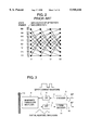
- FIG. 2 is a diagram showing a trellis diagram of an extended partial response class 4 according to the prior art
- FIG. 3 is a schematic block diagram showing an arrangement in which a Viterbi decoder according to the prior art is used to make a magnetic recording channel;
- FIG. 4 is a schematic block diagram showing a logical arrangement of a Viterbi decoder
- FIG. 5 is a schematic diagram used to explain the manner in which a trellis diagram is transformed under a distributive law according to the prior art
- FIGS. 6A through 6C are schematic diagrams used to explain the manner in which trellis diagrams of an extended partial response class 4 are transformed according to the prior art, respectively;
- FIG. 7 is a schematic diagram used to explain the manner in which a trellis diagram is transformed according to the prior art
- FIG. 8 is a schematic diagram showing trellis diagrams of calculations of two stages in an extended partial response class 4 according to the present invention.
- FIG. 9 is a schematic diagram showing a result in which the trellis diagrams of the extended partial response class 4 according to the present invention are transformed into two stages;
- FIGS. 10A and 10B are tables showing constants which are compared with differences of survivor path metrics according to the present invention, respectively;
- FIG. 11 is a schematic block diagram showing an ACSU (add-compare-select unit) of a Viterbi decoder that is modified so as to act on the trellis diagram of FIG. 9;
- ACSU add-compare-select unit
- FIG. 12 is a schematic block diagram used to explain a compare/select unit shown in FIG. 11;
- FIG. 13 is a schematic block diagram used to explain a decoder shown in FIG. 12;
- FIG. 14 is a schematic block diagram showing a BMU (branch metric unit) of a Viterbi decoder that is modified so as to act on the trellis diagram of FIG. 9;
- FIG. 15 is a diagram showing a trellis diagram of calculations of three stages of the extended partial response class 4 according to the present invention.
- FIG. 16 is a diagram showing a trellis diagram of an extended partial response class 4 according to the present invention in which a calculation of three stages is modified into a calculation of one stage;
- FIG. 17 is a schematic block diagram showing a magnetic recording and reproducing system to which the present invention is applied.
- FIG. 18 is a block diagram showing another example of the BMU of the Viterbi decoder which is modified so as to act on the trellis diagram of FIG. 9.
- the present invention is not limited to the magnetic recording and reproducing system, and may be similarly applied to a reproducing apparatus exclusively designed for reproducing magnetic recorded data, for example.
- FIG. 17 is a schematic block diagram showing the above-mentioned magnetic recording and reproducing system.
- a magnetic recording and reproducing system is adapted to record data outputted from a host apparatus 110 such as a computer on a recording medium 150, and is also adapted to read out magnetic recorded data from the recording medium 150. Then, the magnetic recording and reproducing system 100 outputs the magnetic data thus read out to the host apparatus 110.
- the magnetic recording and reproducing system 100 includes an encoder 120, an amplifier 130 and a write head 140 as main components for writing data on the recording medium 150.
- the magnetic recording and reproducing system 100 includes a read head 160, a digital signal decoding apparatus 180 and an error correcting circuit 190 as main components for reading out data from the recording medium 150.
- read data symbol sequence which is read out from the recording medium 150 by the read head 160, is amplified by a preamplifier 170, and then supplied to a filter 200, in which its high-frequency noise is eliminated. Then, the read data symbol sequence of which the high-frequency noise was eliminated by the filter 200 is converted by an ADC (analog-to-digital converter) 210 into a digital signal, and supplied to an equalizer 220, in which it is equalized for decoding.
- ADC analog-to-digital converter
- a decoding circuit 230 which is a main component of the present invention, receives the equalized read data symbol sequence as the input data symbol sequence, and reproduces the equalized read data symbol sequence as a digital signal, i.e. binary code sequence which is not yet encoded.
- a VCO (voltage-controlled oscillator) 240 generates a clock signal CLK 250, which determines an operation timing of each unit, in response to an output from the equalizer 220.
- the above-mentioned digital signal decoding apparatus 180 can attain the aforementioned objects of the present invention by replacing the conventional decoder 230 with a decoder in which an increase of a circuit scale can be suppressed and which can be operated at high speed which will be described below.
- a calculation of a survivor path is carried out by one ACS (Add-Compare-Select) calculation at every plurality of sampling periods.
- ACS Additional Compare-Select
- a Viterbi decoding method comprises the steps of (a) selecting survivor paths reaching respective calculated states of a plurality of stages by comparing differences among metrics of respective nodes of the present time with constant values unrelated to the recursive step; and (b) adding branch metrics shifted in the respective nodes in the calculated states of a plurality of stages based on a trellis diagram in which a plurality of consecutive sampling data are modified in such a manner that metric calculations concerning respective sample data are shifted to the outside of metric comparison and path selection calculations on the trellis diagram.
- an encoder of EPR4 (hereinafter simply referred to as "encoder") 5 will be described with reference to a conceptual diagram of FIG. 1A and a state diagram of FIG. 1B.
- the encoder 5 receives a binary input waveform at a sampling rate of 1/T, and generates a quinary output at the same rate.
- a binary input is supplied through a path 1, and inputted to a shift register 2.
- An output c(i) that is outputted from the encoder 5 through a path 3 becomes a quinary output ⁇ +2, +1, 0, -1, -2 ⁇ as a calculated result of an adder 4 for b(i), b(i-1), b(i-2), b(i-3).
- the three registers b(i-3), b(i-2), b(i-1) are adapted to express states ⁇ 000, 001, 010, 011, 100, 101, 110, 111 ⁇ of 8 different finite-state machines as shown in FIG. 1B.
- Input and output of the encoder 5 are labeled to the transition between the states.
- ⁇ 0 ⁇ is inputted in the state of 000, for example, the encoder 5 generates 0 as an output, and the state of the encoder 5 is maintained at 000, which state is expressed in the form of "0/0".
- the encoder 5 begins with the state of 000 and receives an input of 1, the encoder 5 generates an output of 1, and transited to the state of 001. This is also true when the encoder 5 is transited from other states.
- FIG. 2 shows a trellis diagram corresponding to the state diagram of FIG. 1B.
- the trellis diagram is a directed graph and each node thereof expresses the state in which the encoder is placed at a time i.
- Each branch expresses a transition from the state of the time i to the next time i+1.
- an ordinate shows the state corresponding to the node of the state diagram
- an abscissa shows a time (calculation between two times is referred to as "stage calculation").
- FIG. 3 is a block diagram showing a Viterbi decoder, an encoder and a magnetic recording channel.
- a read/write transducer or head and filter assembly (hereinafter simply referred to as “head and filter assembly”) 8 varies a magnetic state of a medium 10 when data is written in the medium 10, and detects the state of a track when data is read out from the medium 10.
- the read/write transducer corresponds to the heads 140, 160 shown in FIG. 17; a digital-to-analog converter (hereinafter simply referred to as "D/A converter”) 6 is included in the amplifier 130 shown in FIG. 17; the filter corresponds to the filter 200 shown in FIG.
- D/A converter digital-to-analog converter
- A/D converter 12 corresponds to the ADC 210 shown in FIG. 17.
- A/D converter 12 an analog-to-digital converter (hereinafter simply referred to as "A/D converter") 12 corresponds to the ADC 210 shown in FIG. 17.
- A/D converter 12 an analog-to-digital converter (hereinafter simply referred to as "A/D converter") 12 corresponds to the ADC 210 shown in FIG. 17.
- the equalizer 220 shown in FIG. 17 is omitted from FIG. 3 in order to simplify the description, in actual practice, an output from the A/D converter 12 is equalized by the equalizer, and then inputted to a Viterbi decoder 14.
- a binary code sequence is supplied to the encoder 5, and a code sequence from the encoder 5 is supplied to the D/A converter 6.
- An analog signal which changes with time is outputted from the D/A converter 6, and supplied to the head and filter assembly 8 in the write direction.
- an analog output which changes with time from the head and filter assembly 8 is supplied to the A/D converter 12.
- An EPR 4 output outputted from the A/D converter 12 is supplied through a path 13 to the Viterbi decoder 14 in the order in which it is are read out from the medium 10.
- the Viterbi decoder 14 outputs a bit sequence of maximum likelihood estimation concerning the first recorded data onto a path 16.
- the EPR4 output is a quinary output of ⁇ +2, +1, 0, -1, -2 ⁇ .
- FIG. 4 shows a logical arrangement of the Viterbi decoder 14.
- reference numeral 18 denotes a branch metric unit (hereinafter simply referred to as "BMU")
- reference numeral 20 denotes an add-compare-select unit (hereinafter simply referred to as "ACSU") having a recursive path 22.
- the ACSU 20 is adapted to function as a Viterbi detector.
- Reference numeral 24 denotes a survivor-path-memory unit (hereinafter simply referred to as "SMU").
- the ACSU 20 processes the quinary symbol data in accordance with the trellis diagram.
- a code sequence traces its own route, and hence this route is referred to as "path".
- the Viterbi decoder compares two paths inputted to each node, holds a path having an optimum metric and discards other paths because the selection of path at that time is made optimum regardless of the code sequence in the succeeding stage calculations.
- the path thus held is referred to as "survivor path”.
- the above-mentioned processes are executed by a recursive calculation method. As an optimum estimation (maximum likelihood estimation) proceeds, the maximum likelihood path (binary code sequence that is encoded first) is stored in the SMU 24.
- a branch metric E in the ERP4 is calculated based on the following square error: ##EQU1## where c is the ideal output obtained from the equalizer 220 in the absence of a noise, and Y k is the actual output 10 obtained from the equalizer 220.
- min(A;B) is a calculation equation for expressing smaller one of A and B.
- the manner in which the trellis diagram shown in FIG. 6A is transformed into the trellis diagram shown in FIG. 6B will be described below with reference to one ACS comprising a node 000 and a node 100 of a time k and a node 000 and a node 001 of a time k+1. If the addition of metric y k +1 is carried out on the left-hand side of the node 100 of the time k, no metric at the branch between the node 100 and the node 000 is added any more, and a metric -y k +1 at the branch between the node 100 and the node 001 is added. If the trellis diagram is similarly transformed with respect to other three ACSs, the trellis diagram shown in FIG.
- any one of the four ACSs includes addition of fixed values (2 or -2) in FIGS. 6A through 6C, one ACS adds fixed values only in one branch as shown in FIG. 7, and the selection of a path having a small metric can be executed with ease as follows:
- M 0 and M 1 assume metrics in the nodes on the left-hand side of one ACS, respectively, M 0 ' and M 1 ' assume metrics in the nodes on the right-hand side after the path was selected, respectively, and C assumes a fixed value on the branch.
- C assumes a fixed value on the branch.
- circuit-scale is reduced to about 1/2 by the transformed EPR4 trellis, a critical path of operation is still based on the compare-select-add, and hence a calculation speed is not increased satisfactorily.
- the calculation for the EPR4 trellis of a plurality of stages shown in FIG. 8 is executed by one stage calculation shown in FIG. 9.
- the transformation is carried out in such a manner that the calculations for the EPR4 of a plurality of stages are shifted to the outside of the recursive loop of the compare-select.
- the present invention is not limited to the calculation of the EPR4 trellis, and may be applied to the trellises of partial response of other classes. The case of the two-stage calculation will be described hereinafter. In order to understand this transform process of trellis more clearly, the following operators are introduced.
- stage calculation (k+1) The vector M k +2! which expresses a metric of each node obtained after the calculation of the stage calculation (k+1) is expressed by the following equation (6) by using a vector M k ! which expresses a metric of each node at the time of k:
- matrixes ⁇ k ! and ⁇ k+1 ! are the branch metrics of the stage k and the stage (k+1), and (i, j) elements of the matrixes are branch metrics ranging from j-th node of the preceding time to i-th node of the next time.
- the branch metrics based on the inputted signals (equalized outputs y k and y k+1 ) of the stage calculation (k+1) and the stage calculation k are independently added to the path metrics of the nodes of the stage calculation k. Accordingly, the simplification on the calculation of the branch metrics of the stage calculation (k+1) and the simplification on the calculation of the branch metrics of the stage calculation k may be carried out independently.
- the node of the time k and the node of the time k+2 may be combined directly, and the values of the branch metrics of the stage k and the stage k+1 may be added for the respective paths.
- a predetermined metric is added before the ACS at the stage k is carried out, and a predetermined metric is added after the ACS at the stage k+1 was ended.
- the process in which the metric is added before the path is selected on the stage k is carried out at the same time the metric is added after the ACSs at the stage k-2 and the stage k-1 were carried out. Therefore, the above-mentioned addition of metric is omitted from the trellis diagram of FIG. 9.
- the branch metric calculation for the trellises of the two-stage calculations is transformed into the process in which calculated results using the value of the input signal from the path 13 are added after the constants were added and the survivor paths were selected.
- the process in which the survivor path is selected can be transformed into the process in which four metric differences in the starting node and the constants are compared with each other.
- Branch metrics L 0 , k+2 through L 7 , k+2 using the input signal added after the comparison and selection in FIG. 9 are respectively given by the following equation (16): ##EQU12## where i in the branch metric L i , k+2 represents the node No.
- Survivor paths are selected by using the metrics M 0 ,k through M 7 ,k of the survivor paths and the branch metrics expressed by the constants. As described above, the whole of this calculation can be transformed into the process in which the metric differences of the survivor paths and the constants are compared with each other. For example, the survivor paths of the node of the state 0 in the time (k+2) in FIG. 9 are selected by calculating the following equation (17):
- FIGS. 10A and 10B show the values of the constants which are compared with metric differences when survivor paths to other nodes are selected, respectively.
- the suffix k that expresses the time NO. is not shown in FIGS. 10A and 10B.
- the middle columns show path metrics to be compared, and the lower columns show values of constants which are compared with differences of survivor path metrics.
- FIG. 10A shows constants which are used to select the survivor paths to the 0-th, second, fourth and sixth nodes by using M 0 ,k, M 1 ,k, M 2 ,k and M 3 ,k
- FIG. 10B shows constants which are used to select the survivor paths to the first, third, fifth and seventh nodes by using M 4 ,k, M 5 ,k, M 6 ,k and M 7 ,k, respectively.
- the survivor paths are determined in accordance with the results obtained when the metric differences and the constants are compared with each other.
- ⁇ i is the branch metric of the constants between the time k and the time (k+2). Since the process in which the branch metric ⁇ i and the branch metrics L i ,k+2 using the input signal are added can be executed by another operation unit, the calculation in the equation (19) can be executed by one addition.
- the survivor paths of the two-stage calculations can be selected in the operation cycle of compare-select-add by using the trellis comprising the two-stage calculations of the EPR4 trellis.
- the ACSU 20 for processing the transformed trellis shown in FIG. 9 will be described with reference to FIG. 11.
- reference numerals 26, 28 denote operation units (hereinafter simply referred to as "C/S 26, 28") which are used to carry out the above-mentioned compare/select operations.
- the C/S 26, 28 are adapted to output metrics M 0 ' through M 7 ' at the respective stages k of newly selected survivor paths together with survivor sequence pointers SMO, SM2, SM6 and SM1, SM3, SM5, SM7 by comparing four survivor metrics inputted thereto so far.
- the C/S 26 is the operation unit supplied with M 0 ,k, M 1 ,k, M 2 ,k, M 3 ,k shown in FIG.
- the C/S 28 is the operation unit supplied with M 4 ,k, M 5 ,k, M 6 ,k, M 7 ,k shown in FIG. 9, and then outputs M 1 ', M 3 ', M 5 ', M 7 '.
- the survivor sequence pointers SMO, SM2, SM6, SM1, SM3, SM5, SM7 are also used to control the contents of the SMU 24.
- the C/S 26, 28 are adapted only to select the survivor paths, and do not carry out the addition of the above-mentioned constants. Therefore, as will be described later on, the BMU 18 generates branch metric nominates using the constants and the input signal.
- a selector (hereinafter simply referred to as "SEL") 61 selects any one of the branch metric nominates outputted from the BMU 18 in accordance with the survivor sequence pointers SM0 through SM7.
- Adders 30, 32, 34, 36, 38, 40, 42, 44 are adapted to obtain metrics of respective nodes at the time (k+2) shown in FIG. 9 by adding any of the values (B 0 to B 7 ) of the selected branch metrics or the constant value (-2) to the metrics of the respective nodes at the time k in FIG. 9. The results thus obtained are fed back to the corresponding states for executing the next operation cycle.
- the outputs M 0 ', M 2 ' corresponding to the constants M 0 ,k, M 2 ,k in FIG. 9 are supplied from the CIS 26 to the adders 30, 32, in which they are respectively added with the values B 0 , B 2 .
- Resulting sums are memorized in respective registers (each of which is denoted by "LT" in FIG. 11 for simplicity) for executing the next operation cycle, and fed back to the inputs M 0 , M 2 of the C/S 26.
- the outputs M 4 ', M 6 ' corresponding to the constants M 4 ,k, M 6 ,k shown in FIG. 9 are respectively added to the values B 4 , B 6 by the adders 34, 36. Resulting sums are memorized in respective registers (each of which is denoted by "LT" in FIG. 11 for simplicity) for computing the states 1, 3, 5, 7 in the next operation cycle, and fed back to the inputs M 4 , M 6 of the C/S 28.
- the outputs M 5 ', M 7 ' corresponding to the constants M 5 ,k, M 7 ,k shown in FIG. 9 are supplied to the adders 42, 44, in which they are respectively added to the values B 5 , B 7 .
- Resulting sums are memorized in respective registers (each of which is denoted by "LT" in FIG. 11 for simplicity) for executing the next operation cycle, and fed back to the inputs M 5 , M 7 of the C/S 28.
- the outputs M 1 ', M 3 ' corresponding to the constants M 1 ,k, M 3 ,k shown in FIG. 9 are respectively added to the values B 1 , B 3 by the adders 38, 40.
- Resulting sums are respectively memorized in registers (each of which is denoted by "LT" in FIG. 11 for simplicity) for calculating the states 0, 2, 4, 6 in the next operation cycle, and fed back to the inputs M 1 , M 3 of the C/S 26.
- FIG. 12 is a block diagram showing the C/S 26 more in detail. Although adders and comparators in the C/S 26 are independently illustrated in FIG. 12, it is needless to say that they may be formed of one operation unit. Metrics of survivor paths in the states 0, 1, 2, 3 are inputted to the C/S 26. Adders 72, 74, 76, 78, 80, 82 are adapted to calculate differences M 0 -M 1 , M 0 -M 2 , M 0 -M 3 , M 1 -M 2 , M 1 -M 3 , M 2 -M 3 of all combinations of the metrics of the survivor paths.
- Comparators 84, 86, 88, 90, 92, 94 are each adapted to compare differences of respective metrics and constant values.
- the constant values that are compared with the differences are those illustrated on FIG. 10A.
- the comparator (hereinafter simply referred to as "COMP") 84 compares 0 and 2.
- the comparator COMP 86 compares -2, 0, 2, and 4. Similar comparisons are effected on the differences M 0 -M 3 , M 1 -M 2 , M 1 -M 3 , M 2 -M 3 of other survivor path metrics.
- a decoder circuit (hereinafter simply referred to as "DEC") 98 determines the survivor paths to the states 0, 2, 4, 6 based on the compared results from the comparators COMP 84, 86, 88, 90, 92, 94.
- FIG. 13 is a block diagram showing the decoder DEC 98 more in detail. The manner in which the survivor path to the state 0, for example, is determined will be described. Inputs from the comparators COMP 84, 86, 88, 90, 92, 94 to the decoder DEC 98 are respectively 2, 4, 6, 2, 4, 2 with respect to the metric differences M 0 -M 1 , M 0 -M 2 , M 0 -M 3 , M 1 -M 2 , M 1 -M 3 , M 2 -M 3 as shown on the column of the node 0 in FIG. 10A.
- a bit "1" is outputted to the position at which the path of the smallest value of M 0 -4, M 1 -2, M 2 , M 3 +2 from above is illustrated.
- an output 300 is "1” and outputs 301 to 303 are "0"
- the node 0 at the time k+2 demonstrates that the path from the node 0 at the time k is a survivor path.
- outputs SM0, SM2, SM4, SM6 from the decoder DEC 98 are supplied to a selector (hereinafter simply referred to as "SEL") 96 which derives metrics M 0 ', M 2 ', M 4 ', M 6 ' of the corresponding survivor paths.
- SEL selector
- FIG. 14 is a block diagram showing the BMU 18 more in detail.
- the following branch metric nominates become necessary in order to simultaneously add branch metrics using the constants and the input signals after a survivor path was selected. ##EQU13##
- circuit scale of the Viterbi decoder using the above-mentioned method and units according to the present invention will hereinafter be compared with that of the Viterbi decoder using the method and units according to the prior art.
- the method and units according to the prior art require 80 variable-adders in total.
- 22 variable-adders and 32 constant-adders are required as the operation units in total.
- the constant-adder is required to calculate only high-order bits, and hence the constant-adder is simpler than the variable-adder from a circuit arrangement standpoint. Having considered this fact, it is to be noted that the Viterbi decoder based on the method and units according to the present invention can reduce its circuit scale to about 50% as compared with the circuit arrangement composed by the prior-art method and units.
- the ACSU 20 calculates the branch metrics at every two stages so that each latch (LT) clock of the BMU 18 has a frequency twice as high as the frequency of the clock of each latch (LT) within the ACSU 20.
- FIG. 18 is a block diagram showing an example of a circuit of the BMU 18 for calculating branch metrics at every two-stage calculation.
- the respective latch (LT) clocks of the BMU 18 and the ACSU 20 have the same frequency so that it becomes possible to reduce a power consumption of the digital signal decoding apparatus much more.
- to change the Viterbi detection of the extended partial response waveform on the trellis diagram i.e. to calculate the sampling (reproduced) data of a plurality of consecutive two stages on the trellis diagram can be carried out in a batch processing fashion.
- a time required by such calculation can be reduced to substantially 1/2 by the devised calculation method.
- a vector M k+3 ! which expresses the metric of each node at the time (k+3) is expressed by using a vector M k ! which expresses the metric of each node at the time k as follows:
- matrixes ⁇ k !, ⁇ k+1 ! and ⁇ k+2 ! are the branch metrics of the stage calculations (k), (k+1), (k+2), and the (i,j) elements of each matrix are branch metrics ranging from the j-th node of the preceding time to the i-th node of the succeeding time.
- the branch metric calculations for the three-stage trellis are all transformed into the additions of the constants and the addition of computed results using the value of the inputted signal from the path 13 after the survivor path was selected. Furthermore, the selection of the survivor path can be transformed into the comparison between the eight metric differences at the starting node and the constants.
- the three-stage calculations of the EPR4 trellis can be processed together hereinafter in a batch processing fashion similarly to the above-mentioned trellis processing of two-stage calculations.
- code sequence is based on the extended partial response class 4 (EPR4) as described above, the present invention is not limited thereto, and may be similarly applied to an extended partial response EnPR4 (n ⁇ 2) which is further extended to n-tuple.
- EPR4 extended partial response class 4
Landscapes
- Physics & Mathematics (AREA)
- Probability & Statistics with Applications (AREA)
- Engineering & Computer Science (AREA)
- Theoretical Computer Science (AREA)
- Signal Processing (AREA)
- Error Detection And Correction (AREA)
- Dc Digital Transmission (AREA)
Abstract
Description
min(x+a;y+b)=min(x;y+b-a)+a (3)
x×a⊕y×b=(x×(y+b-a))×a (5)
M.sub.k+2 != λ.sub.k+1 !× λ.sub.k !× M.sub.k !(6)
λ.sub.c +λ.sub.-c =2 (15)
min(M.sub.0,k-4, M.sub.1,k -2, M.sub.2k, M.sub.3,k +2) (17)
M.sub.0,k -M.sub.1,k ≈2, M.sub.0,k -M.sub.2,k ≈4, M.sub.0,k -M.sub.3,k ≈ 6
M.sub.1,k -M.sub.2,k ≈2 M.sub.1,k -M.sub.3,k ≈4, M.sub.2,k -M.sub.3,k ≈2 (18)
M.sub.i,k+2 =M.sub.SMi,k +(α.sub.i +L.sub.i,k+2)(i=0, 1, . . . , 7)(19)
M.sub.k+3 != λ.sub.k+2 !× λ.sub.k+1 !× λ.sub.k !× M.sub.k ! (22)
Claims (9)
Applications Claiming Priority (2)
| Application Number | Priority Date | Filing Date | Title |
|---|---|---|---|
| JP16897696A JP3344221B2 (en) | 1996-06-28 | 1996-06-28 | Digital signal decoding apparatus and decoding method used therefor |
| JP8-168976 | 1996-06-28 |
Publications (1)
| Publication Number | Publication Date |
|---|---|
| US5940416A true US5940416A (en) | 1999-08-17 |
Family
ID=15878058
Family Applications (1)
| Application Number | Title | Priority Date | Filing Date |
|---|---|---|---|
| US08/881,508 Expired - Lifetime US5940416A (en) | 1996-06-28 | 1997-06-24 | Digital signal decoding apparatus and a decoding method used therein |
Country Status (2)
| Country | Link |
|---|---|
| US (1) | US5940416A (en) |
| JP (1) | JP3344221B2 (en) |
Cited By (19)
| Publication number | Priority date | Publication date | Assignee | Title |
|---|---|---|---|---|
| US6216249B1 (en) | 1999-03-03 | 2001-04-10 | Cirrus Logic, Inc. | Simplified branch metric for reducing the cost of a trellis sequence detector in a sampled amplitude read channel |
| WO2001029974A1 (en) * | 1999-10-21 | 2001-04-26 | Qualcomm Incorporated | High-speed acs unit for a viterbi decoder |
| US6405342B1 (en) | 1999-09-10 | 2002-06-11 | Western Digital Technologies, Inc. | Disk drive employing a multiple-input sequence detector responsive to reliability metrics to improve a retry operation |
| US20020073378A1 (en) * | 2000-12-13 | 2002-06-13 | Jia-Horng Shieh | Viterbi detector for partial response maximum likelihood signal processing |
| US6459851B1 (en) * | 1998-12-29 | 2002-10-01 | Oak Technology, Inc. | Apparatus for processing audio and video DVD data |
| US20020174402A1 (en) * | 2001-05-18 | 2002-11-21 | Matsushita Electric Industrial Co., Ltd. | Viterbi detector |
| US20030007578A1 (en) * | 2000-12-22 | 2003-01-09 | Kuo Hung-Chenh | Decoding circuit and method of viterbi decoder |
| US6625225B1 (en) | 1999-10-29 | 2003-09-23 | Matsushita Electric Industrial Co., Ltd. | Trellis decoder and associated method |
| US20030196163A1 (en) * | 2002-04-15 | 2003-10-16 | Hong-Ching Chen | ACS circuit and viterbi decoder with the circuit |
| US20040003340A1 (en) * | 2002-06-26 | 2004-01-01 | 3Dsp Corporation | Modulo arithmetic overflow control for viterbi decoder |
| US20040010749A1 (en) * | 2002-07-12 | 2004-01-15 | Stmicroelectronics, Inc. | E2PR4 viterbi detector and method for adding a branch metric to the path metric of the surviving path after selecting the surviving path |
| US20040122883A1 (en) * | 2002-12-18 | 2004-06-24 | Lee Seok-Jun | High speed add-compare-select circuit for radix-4 Viterbi decoder |
| US20050066259A1 (en) * | 2003-09-20 | 2005-03-24 | Samsung Electronics Co., Ltd. | Viterbi detection apparatus and method therefor |
| US20050111532A1 (en) * | 1999-04-22 | 2005-05-26 | Creigh John J. | Physical coding sublayer for a multi-pair gigabit transceiver |
| US7035356B1 (en) * | 2000-11-03 | 2006-04-25 | Altera Corporation | Efficient method for traceback decoding of trellis (Viterbi) codes |
| US20070124658A1 (en) * | 2003-04-29 | 2007-05-31 | Ubinetics Limited | Acs apparatus and method for viterbi decoder |
| US20090089556A1 (en) * | 2002-12-18 | 2009-04-02 | Texas Instruments Incorporated | High-Speed Add-Compare-Select (ACS) Circuit |
| US20150019458A1 (en) * | 2013-07-10 | 2015-01-15 | International Business Machines Corporation | Multistage optimization of asset health versus costs to meet operation targets |
| US11405136B1 (en) * | 2021-04-22 | 2022-08-02 | Silicon Laboratories Inc. | Viterbi equalizer with soft decisions |
Families Citing this family (2)
| Publication number | Priority date | Publication date | Assignee | Title |
|---|---|---|---|---|
| JP3634842B2 (en) | 2002-12-27 | 2005-03-30 | 株式会社東芝 | Digital signal decoding apparatus and digital signal decoding method |
| JP4840651B2 (en) * | 2006-07-27 | 2011-12-21 | ソニー株式会社 | Decoding device and decoding method |
Citations (2)
| Publication number | Priority date | Publication date | Assignee | Title |
|---|---|---|---|---|
| US4777363A (en) * | 1986-08-29 | 1988-10-11 | Research Corporation Technologies, Inc. | Ion mobility spectrometer |
| US5430744A (en) * | 1993-09-30 | 1995-07-04 | International Business Machines Corporation | Method and means for detecting partial response waveforms using a modified dynamic programming heuristic |
-
1996
- 1996-06-28 JP JP16897696A patent/JP3344221B2/en not_active Expired - Fee Related
-
1997
- 1997-06-24 US US08/881,508 patent/US5940416A/en not_active Expired - Lifetime
Patent Citations (2)
| Publication number | Priority date | Publication date | Assignee | Title |
|---|---|---|---|---|
| US4777363A (en) * | 1986-08-29 | 1988-10-11 | Research Corporation Technologies, Inc. | Ion mobility spectrometer |
| US5430744A (en) * | 1993-09-30 | 1995-07-04 | International Business Machines Corporation | Method and means for detecting partial response waveforms using a modified dynamic programming heuristic |
Cited By (32)
| Publication number | Priority date | Publication date | Assignee | Title |
|---|---|---|---|---|
| US6459851B1 (en) * | 1998-12-29 | 2002-10-01 | Oak Technology, Inc. | Apparatus for processing audio and video DVD data |
| US6216249B1 (en) | 1999-03-03 | 2001-04-10 | Cirrus Logic, Inc. | Simplified branch metric for reducing the cost of a trellis sequence detector in a sampled amplitude read channel |
| US7607052B2 (en) * | 1999-04-22 | 2009-10-20 | Broadcom Corp. | Physical coding sublayer for a multi-pair gigabit transceiver |
| US20050111532A1 (en) * | 1999-04-22 | 2005-05-26 | Creigh John J. | Physical coding sublayer for a multi-pair gigabit transceiver |
| US6405342B1 (en) | 1999-09-10 | 2002-06-11 | Western Digital Technologies, Inc. | Disk drive employing a multiple-input sequence detector responsive to reliability metrics to improve a retry operation |
| WO2001029974A1 (en) * | 1999-10-21 | 2001-04-26 | Qualcomm Incorporated | High-speed acs unit for a viterbi decoder |
| US6333954B1 (en) | 1999-10-21 | 2001-12-25 | Qualcomm Incorporated | High-speed ACS for Viterbi decoder implementations |
| KR100779782B1 (en) * | 1999-10-21 | 2007-11-27 | 콸콤 인코포레이티드 | High Speed ACS Unit for Viterbi Decoder |
| US6625225B1 (en) | 1999-10-29 | 2003-09-23 | Matsushita Electric Industrial Co., Ltd. | Trellis decoder and associated method |
| US7035356B1 (en) * | 2000-11-03 | 2006-04-25 | Altera Corporation | Efficient method for traceback decoding of trellis (Viterbi) codes |
| US6792571B2 (en) * | 2000-12-13 | 2004-09-14 | Acer Laboratories Inc. | Viterbi detector for partial response maximum likelihood signal processing |
| US20020073378A1 (en) * | 2000-12-13 | 2002-06-13 | Jia-Horng Shieh | Viterbi detector for partial response maximum likelihood signal processing |
| US6999532B2 (en) * | 2000-12-22 | 2006-02-14 | Media Tek Inc. | Decoding circuit and method of Viterbi decoder |
| US20030007578A1 (en) * | 2000-12-22 | 2003-01-09 | Kuo Hung-Chenh | Decoding circuit and method of viterbi decoder |
| US20060072687A1 (en) * | 2000-12-22 | 2006-04-06 | Media Tek Inc. | Decoding circuit and decoding method for a Viterbi decoder |
| US20020174402A1 (en) * | 2001-05-18 | 2002-11-21 | Matsushita Electric Industrial Co., Ltd. | Viterbi detector |
| US7426681B2 (en) * | 2001-05-18 | 2008-09-16 | Matsushita Electric Industrial Co., Ltd. | Viterbi detector |
| US7581160B2 (en) | 2002-04-15 | 2009-08-25 | Mediatek Inc. | ACS circuit and Viterbi decoder with the circuit |
| US20030196163A1 (en) * | 2002-04-15 | 2003-10-16 | Hong-Ching Chen | ACS circuit and viterbi decoder with the circuit |
| US7127667B2 (en) * | 2002-04-15 | 2006-10-24 | Mediatek Inc. | ACS circuit and viterbi decoder with the circuit |
| US20070044008A1 (en) * | 2002-04-15 | 2007-02-22 | Mediatek, Inc. | ACS circuit and Viterbi decoder with the circuit |
| US20040003340A1 (en) * | 2002-06-26 | 2004-01-01 | 3Dsp Corporation | Modulo arithmetic overflow control for viterbi decoder |
| US20080270874A1 (en) * | 2002-07-12 | 2008-10-30 | Stmicroelectronics, Inc. | E2PR4 viterbi detector and method for adding a branch metric to the path metric of the surviving path after selecting the surviving path |
| US7290200B2 (en) * | 2002-07-12 | 2007-10-30 | Stmicroelectronics, Inc. | E2PR4 viterbi detector and method for adding a branch metric to the path metric of the surviving path after selecting the surviving path |
| US20040010749A1 (en) * | 2002-07-12 | 2004-01-15 | Stmicroelectronics, Inc. | E2PR4 viterbi detector and method for adding a branch metric to the path metric of the surviving path after selecting the surviving path |
| US20040122883A1 (en) * | 2002-12-18 | 2004-06-24 | Lee Seok-Jun | High speed add-compare-select circuit for radix-4 Viterbi decoder |
| US20090089556A1 (en) * | 2002-12-18 | 2009-04-02 | Texas Instruments Incorporated | High-Speed Add-Compare-Select (ACS) Circuit |
| US8205145B2 (en) | 2002-12-18 | 2012-06-19 | Texas Instruments Incorporated | High-speed add-compare-select (ACS) circuit |
| US20070124658A1 (en) * | 2003-04-29 | 2007-05-31 | Ubinetics Limited | Acs apparatus and method for viterbi decoder |
| US20050066259A1 (en) * | 2003-09-20 | 2005-03-24 | Samsung Electronics Co., Ltd. | Viterbi detection apparatus and method therefor |
| US20150019458A1 (en) * | 2013-07-10 | 2015-01-15 | International Business Machines Corporation | Multistage optimization of asset health versus costs to meet operation targets |
| US11405136B1 (en) * | 2021-04-22 | 2022-08-02 | Silicon Laboratories Inc. | Viterbi equalizer with soft decisions |
Also Published As
| Publication number | Publication date |
|---|---|
| JP3344221B2 (en) | 2002-11-11 |
| JPH1022840A (en) | 1998-01-23 |
Similar Documents
| Publication | Publication Date | Title |
|---|---|---|
| US5940416A (en) | Digital signal decoding apparatus and a decoding method used therein | |
| US5430744A (en) | Method and means for detecting partial response waveforms using a modified dynamic programming heuristic | |
| US5341386A (en) | Viterbi equalizer and recording/reproducing device using the same | |
| US7581160B2 (en) | ACS circuit and Viterbi decoder with the circuit | |
| US6097769A (en) | Viterbi detector using path memory controlled by best state information | |
| US5432820A (en) | Maximum-likelihood decoding method and device | |
| US7380199B2 (en) | Method and apparatus for precomputation and pipelined selection of branch metrics in a reduced-state Viterbi detector | |
| US5548600A (en) | Method and means for generating and detecting spectrally constrained coded partial response waveforms using a time varying trellis modified by selective output state splitting | |
| KR100675391B1 (en) | Detection device | |
| US6373413B1 (en) | Data decoding apparatus and data decoding method | |
| US7370266B2 (en) | Digital signal decoding device and digital signal decoding method | |
| JP3861409B2 (en) | Digital signal reproduction device | |
| US7426681B2 (en) | Viterbi detector | |
| US5996112A (en) | Area-efficient surviving paths unit for Viterbi decoders | |
| JP4099730B2 (en) | Digital signal reproduction device | |
| US7860181B2 (en) | Decoding apparatus and decoding method | |
| US6580766B1 (en) | Partial response maximum likelihood (PRML) bit detection apparatus | |
| US7590926B2 (en) | Decoding apparatus, decoding method, program-recording medium, program and recording/reproduction apparatus | |
| KR100945488B1 (en) | Viterbi detection device and method | |
| JP3634879B2 (en) | Output signal fast decoding method and apparatus | |
| KR100238322B1 (en) | Viterbi detection method and apparatus | |
| JP3674142B2 (en) | Digital information reproducing apparatus and maximum likelihood decoding apparatus | |
| JPH11312984A (en) | Viterbi decoding method, Viterbi decoder, signal processing integrated circuit, data reproducing device, magnetic disk device, and information processing system | |
| WO1994000843A1 (en) | Alternative system and method to viterbi detection | |
| KR19990003318A (en) | Synchronous partial response channel data detector of digital magnetic recording / reproducing system |
Legal Events
| Date | Code | Title | Description |
|---|---|---|---|
| AS | Assignment |
Owner name: HITACHI, LTD., JAPAN Free format text: ASSIGNMENT OF ASSIGNORS INTEREST;ASSIGNORS:NISHIYA, TAKUSHI;YAMAKAWA, HIDEYUKI;MIYAZAWA, SHOICHI (DECEASED);AND OTHERS;REEL/FRAME:008857/0765 Effective date: 19970616 |
|
| STCF | Information on status: patent grant |
Free format text: PATENTED CASE |
|
| FEPP | Fee payment procedure |
Free format text: PAYOR NUMBER ASSIGNED (ORIGINAL EVENT CODE: ASPN); ENTITY STATUS OF PATENT OWNER: LARGE ENTITY |
|
| FPAY | Fee payment |
Year of fee payment: 4 |
|
| AS | Assignment |
Owner name: HITACHI GLOBAL STORAGE TECHNOLOGIES JAPAN, LTD., J Free format text: ASSIGNMENT OF ASSIGNORS INTEREST;ASSIGNOR:HITACHI, LTD.;REEL/FRAME:014675/0272 Effective date: 20031027 |
|
| FPAY | Fee payment |
Year of fee payment: 8 |
|
| FEPP | Fee payment procedure |
Free format text: PAYER NUMBER DE-ASSIGNED (ORIGINAL EVENT CODE: RMPN); ENTITY STATUS OF PATENT OWNER: LARGE ENTITY |
|
| FPAY | Fee payment |
Year of fee payment: 12 |
|
| AS | Assignment |
Owner name: WESTERN DIGITAL TECHNOLOGIES, INC., CALIFORNIA Free format text: ASSIGNMENT OF ASSIGNORS INTEREST;ASSIGNOR:HGST NETHERLANDS B.V.;REEL/FRAME:040818/0551 Effective date: 20160831 |