US5896924A - Computer controlled gas lift system - Google Patents
Computer controlled gas lift system Download PDFInfo
- Publication number
- US5896924A US5896924A US08/812,467 US81246797A US5896924A US 5896924 A US5896924 A US 5896924A US 81246797 A US81246797 A US 81246797A US 5896924 A US5896924 A US 5896924A
- Authority
- US
- United States
- Prior art keywords
- sensors
- valve
- gas lift
- adjustable flow
- rate gas
- Prior art date
- Legal status (The legal status is an assumption and is not a legal conclusion. Google has not performed a legal analysis and makes no representation as to the accuracy of the status listed.)
- Expired - Fee Related
Links
- 239000012530 fluid Substances 0.000 claims description 57
- 238000004519 manufacturing process Methods 0.000 claims description 23
- 230000002441 reversible effect Effects 0.000 claims description 6
- 230000003247 decreasing effect Effects 0.000 claims description 3
- 238000007789 sealing Methods 0.000 claims 1
- 230000001953 sensory effect Effects 0.000 abstract description 4
- 239000007789 gas Substances 0.000 description 65
- 238000002347 injection Methods 0.000 description 7
- 239000007924 injection Substances 0.000 description 7
- 238000004891 communication Methods 0.000 description 4
- 238000012545 processing Methods 0.000 description 4
- 238000005086 pumping Methods 0.000 description 4
- 230000008901 benefit Effects 0.000 description 3
- 230000001965 increasing effect Effects 0.000 description 3
- 239000007788 liquid Substances 0.000 description 3
- 230000001276 controlling effect Effects 0.000 description 2
- 230000001939 inductive effect Effects 0.000 description 2
- 230000013011 mating Effects 0.000 description 2
- 230000007246 mechanism Effects 0.000 description 2
- 230000001105 regulatory effect Effects 0.000 description 2
- 239000007787 solid Substances 0.000 description 2
- 239000004215 Carbon black (E152) Substances 0.000 description 1
- 230000009471 action Effects 0.000 description 1
- 230000005540 biological transmission Effects 0.000 description 1
- 230000015572 biosynthetic process Effects 0.000 description 1
- 230000000903 blocking effect Effects 0.000 description 1
- 230000008859 change Effects 0.000 description 1
- 230000007812 deficiency Effects 0.000 description 1
- 238000010586 diagram Methods 0.000 description 1
- 238000006073 displacement reaction Methods 0.000 description 1
- 230000009977 dual effect Effects 0.000 description 1
- 230000000694 effects Effects 0.000 description 1
- 230000005484 gravity Effects 0.000 description 1
- 230000036541 health Effects 0.000 description 1
- 229930195733 hydrocarbon Natural products 0.000 description 1
- 150000002430 hydrocarbons Chemical class 0.000 description 1
- 230000003993 interaction Effects 0.000 description 1
- 238000003754 machining Methods 0.000 description 1
- 239000000463 material Substances 0.000 description 1
- 238000000034 method Methods 0.000 description 1
- 239000000203 mixture Substances 0.000 description 1
- 238000012986 modification Methods 0.000 description 1
- 230000004048 modification Effects 0.000 description 1
- 230000003287 optical effect Effects 0.000 description 1
- 238000005457 optimization Methods 0.000 description 1
- 230000002028 premature Effects 0.000 description 1
- 230000002035 prolonged effect Effects 0.000 description 1
- 230000004044 response Effects 0.000 description 1
- 230000000717 retained effect Effects 0.000 description 1
- 238000003860 storage Methods 0.000 description 1
- 238000006467 substitution reaction Methods 0.000 description 1
- 238000011144 upstream manufacturing Methods 0.000 description 1
- XLYOFNOQVPJJNP-UHFFFAOYSA-N water Substances O XLYOFNOQVPJJNP-UHFFFAOYSA-N 0.000 description 1
Images


Classifications
-
- E—FIXED CONSTRUCTIONS
- E21—EARTH OR ROCK DRILLING; MINING
- E21B—EARTH OR ROCK DRILLING; OBTAINING OIL, GAS, WATER, SOLUBLE OR MELTABLE MATERIALS OR A SLURRY OF MINERALS FROM WELLS
- E21B34/00—Valve arrangements for boreholes or wells
- E21B34/06—Valve arrangements for boreholes or wells in wells
- E21B34/066—Valve arrangements for boreholes or wells in wells electrically actuated
-
- E—FIXED CONSTRUCTIONS
- E21—EARTH OR ROCK DRILLING; MINING
- E21B—EARTH OR ROCK DRILLING; OBTAINING OIL, GAS, WATER, SOLUBLE OR MELTABLE MATERIALS OR A SLURRY OF MINERALS FROM WELLS
- E21B43/00—Methods or apparatus for obtaining oil, gas, water, soluble or meltable materials or a slurry of minerals from wells
- E21B43/12—Methods or apparatus for controlling the flow of the obtained fluid to or in wells
- E21B43/121—Lifting well fluids
- E21B43/122—Gas lift
- E21B43/123—Gas lift valves
-
- E—FIXED CONSTRUCTIONS
- E21—EARTH OR ROCK DRILLING; MINING
- E21B—EARTH OR ROCK DRILLING; OBTAINING OIL, GAS, WATER, SOLUBLE OR MELTABLE MATERIALS OR A SLURRY OF MINERALS FROM WELLS
- E21B2200/00—Special features related to earth drilling for obtaining oil, gas or water
- E21B2200/02—Down-hole chokes or valves for variably regulating fluid flow
-
- Y—GENERAL TAGGING OF NEW TECHNOLOGICAL DEVELOPMENTS; GENERAL TAGGING OF CROSS-SECTIONAL TECHNOLOGIES SPANNING OVER SEVERAL SECTIONS OF THE IPC; TECHNICAL SUBJECTS COVERED BY FORMER USPC CROSS-REFERENCE ART COLLECTIONS [XRACs] AND DIGESTS
- Y10—TECHNICAL SUBJECTS COVERED BY FORMER USPC
- Y10T—TECHNICAL SUBJECTS COVERED BY FORMER US CLASSIFICATION
- Y10T137/00—Fluid handling
- Y10T137/2931—Diverse fluid containing pressure systems
- Y10T137/2934—Gas lift valves for wells
Definitions
- the invention relates to well production control systems, and more particularly, to a computer controlled gas lift system.
- gas lift apparati are occasionally employed to stimulate movement of fluid uphole.
- the operation ranges from simply pumping high pressure gas downhole to force fluids uphole to pumping additional fluids into the production fluid lowering the specific gravity thereof and thus increasing the "interest" of the fluid in migrating toward the surface.
- Gas lift apparati are also periodically employed when, a mixture of oil and water collects in the bottom of a gas well casing and tubing in the region of the producing formation and obstructs the flow of gases to the surface.
- gas lift valves are conventionally normally closed restricting the flow of injection gas from the casing into the tubing and are opened to allow the flow of injection gas in response to either a preselected pressure condition or control from the surface.
- surface controlled valves are hydraulically operated. By controlling the flow of a hydraulic fluid from the surface, a poppet valve is actuated to control the flow of fluid into the gas lift valve. The valve is moved from a closed to an open position for as long as necessary to effect the flow of the lift gas.
- Such valves are also position instable. That is, upon interruption of the hydraulic control pressure, the gas lift valve returns to its normally closed configuration.
- gas lift production completions are a closed fluid system which are highly elastic in nature due to the compressibility of the fluids and the frequently great depth of the wells.
- Prior art flow control valves for downhole applications include the disadvantage of not providing a substantial amount of control over the exact amount of gas entering the well. This is because the valve is either open or closed and cannot be regulated. Hydraulically actuated downhole flow control valves also include certain inherent disadvantages as a result of their long hydraulic control lines which result in a delay in the application of control signals to a downhole device. In addition, the use of hydraulic fluids to control valves will not allow transmission of telemetry data from downhole monitors to controls at the surface.
- Boyle et al patented a system capable of adjusting the orifice size of the valve through a range of values, thus providing a broader control over the amount of gas being injected into the system.
- U.S. Pat. No. 5,172,717 to Boyle et al discloses a variable orifice valve for gas lift systems. The system allows for adjustment of the flow through a particular valve body thereby allowing tailoring of the flow rate and alleviation of some of the previous problems in the art.
- the variable orifice valve allows greater control over the quantity and rate of injection of fluids into the well. In particular, more precise control over the flow of injection gas into a dual lift gas lift well completion allows continuous control of the injection pressure into both strings of tubing from a common annulus. This permits control of production pressures and flow rates within the well and results in more efficient production from the well.
- variable orifice valve solve many of the aforementioned problems with its variable orifice valve.
- Variable opening provides some of its own inherent drawbacks such as lack of reliability of "openness" over time. More particularly, scale and other debris can build up and prevent movement more easily on orifice closures which are responsive to small increment movements and, in general, are only moved or adjusted by such small increments. Thus when conditions change downhole over time the variable orifice valve may be unable to comply with the changing conditions and would need to be replaced.
- U.S. Pat. No. 5,483,988 Another adjustable gas lift valve is disclosed in U.S. Pat. No. 5,483,988.
- the disclosure teaches a system having several parts or features but particularly includes an adjustable flow gas lift valve which includes a flow port and a plurality of differently sized nozzles selectively alignable with the port. Sensory devices are employed to maintain information about the state of the valve assembly.
- the variable nozzles are located on the actuator and, therefore, can be rotated into alignment with the orifice port to regulate the amount of gas flowing therethrough as desired.
- valve systems are set forth herein which provide adjustable control of the amount of gas injected into the tubing string and are responsive to downhole sensory data, processing and instructions.
- a housing encloses an electrical motor which is paired with a resolver attached to a ball screw which is used to move a ported sleeve into various positions within the housing. Ports are present on the sleeve and at least one opening is employed on the housing of the tool. Thus, by aligning different numbers of ports in the sleeve with the main annulus opening, the amount of gas entering the tubing string is adjustable and controllable.
- a second embodiment of the invention employs the elements of the first embodiment, however, also employs a multiported housing (as opposed to the single annulus opening of the first embodiment) having variously sized ports to provide even greater adjustability of the amount of flow of gas into the tubing string. In other respects, the embodiment operates as does the first embodiment.
- the third embodiment of the invention employs an electric motor attached to a high pressure hydraulic pump.
- the pump discharges into an expandable bladder which is disposed adjacent several holes or slots in the housing, which slots lead to the casing annulus.
- an expandable bladder which is disposed adjacent several holes or slots in the housing, which slots lead to the casing annulus.
- As pressure increases in a chamber defined by the bladder more of the holes or slots, or a larger percentage of the holes and slots, are blocked by the expanded bladder.
- By decreasing the pressure within the bladder the bladder will shrink and allow pressure from the annulus to move through the slots or holes.
- fluid movement from the annulus to the tubing is electrically controlled by a motor operating a piston moving within a cylinder having ports to the annulus.
- Each port includes a seat and a check ball to seal the port, the check ball being displaceable (unseatable) by the movement of the piston within the cylinder. More specifically, as the piston moves along the cylinder it will contact an increasing number of check balls and unseat them from their respective seats thus allowing a proportionate amount of fluid from the annulus to flow into the tubing.
- This embodiment also includes a matching seat machined to compliment the piston such that if the valve is to be completely sealed, the piston may be moved into contact with the matching seat thus preventing all flow.
- a fifth embodiment of the invention employs at least a plurality of commercially available, conventional fully open/fully closed valves per unit area.
- This arrangement allows for control of the amount of fluid passing into the production fluid in a given area by allowing the operator to selectively open one or more of the plurality of valves located either annularly at a point in the tubing or staggered but closely to the same point. In other words there are clusters of nozzles where a single nozzle would have been in the prior art.
- the term operator is intended to mean an actual human or a computer processor either downhole or at the surface. The system allows incremental increase in flow rate.
- a sixth embodiment is a variation on the fifth embodiment in that the basic premise of employing at least a plurality of individually fully operable/fully closeable valves is retained, however, each of the valves in this embodiment are of different sizes so that single valves or combinations thereof may be opened and closed to provide more control over the amount of fluid moving into the production tubing.
- a seventh embodiment provides a helical valve body which rotatably opens or closes a helical flow path.
- An eighth embodiment provides a flow control system in a side pocket mandrel to allow communication between the primary wellbore and the well annulus.
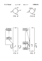
- FIG. 1 is a sectional illustration of a first embodiment of the invention
- FIG. 2 is a sectional view of a second embodiment of the invention.
- FIG. 3 is a sectional view of a third embodiment of the invention.
- FIG. 4 is a sectional view of a fourth embodiment of the invention.
- FIG. 5 is a schematic view of the fifth embodiment of the invention having a multiplicity of valves of like dimensions
- FIG. 6 is a schematic plan view of FIG. 5 taken along lines 6--6;
- FIG. 7 is a schematic view of a sixth embodiment of the invention having a multiplicity of different sized valves
- FIG. 8 is a schematic plan view of FIG. 7 taken along section line 8--8;
- FIG. 9 is a perspective view of another embodiment of the invention employing a helical valve structure
- FIG. 10 is a cut away view of the body of the tool in which the valve structure of FIG. 9 is placed.
- FIG. 11 is a schematic view of the side pocket mandrel embodiment of the invention.
- FIG. 1 a schematic illustration of the first embodiment of the invention is illustrated in cross-section. It will be understood by one of ordinary skill in the art that the entire device is intended to be attached to the outside of the tubing string and has relatively small dimensions.
- the invention is powered by electric line 10 connected to an electric motor 12 (and controlled by a downhole processor) having a resolver 14.
- the motor turns ball screw 18 through gear box 16 which provides axial movement of the sleeve discussed hereunder.
- Shaft 20 of ball screw 18 is preferably isolated from motor 12 by oring 22 which is mounted in housing 24. Housing 24 defines sleeve chamber 26 within which ported sleeve 28 is axially movable.
- a top section of sleeve 28, indicated as box thread 30 includes a pitch complimentary to ball screw 18 and is threaded thereon. Therefore, upon rotational actuation of ball screw 18, ported sleeve 28 is axially movable within chamber 16 of housing 24. Upon such movement of ported sleeve 28 individual ports 32 thereof are selectively alignable with main annulus opening 34, thus allowing fluid to flow from the annulus into chamber 26. Fluid pressure inside chamber 26 will unseat check valve 36 and flow therepast through tubing access opening 38 and into its desired destination of the production string (not shown).
- check valve 36 is energized by spring 40 to maintain it in the closed position. This prevents fluid flowing within the tubing accessed by tubing access opening 38 from contaminating the gas lift valve or the annulus.
- o-rings 42 and 44 which seal against ported sleeve 28.
- Ported sleeve 28 is most preferably constructed from solid rod in which thread 30 is cut and an axial opening is drilled partially into the rod providing through passage for the to ports 32.
- the solid portion of the rod left after machining is body seal 46.
- body seal 46 is contiguous with the mirror (but moved over) image thereof on the other side of the drawing.
- Each of these ports are complimentary in size to ports 50', 52', 54' and 56' of the housing.
- Selective alignment among the ported sleeve ports and housing ports provides control over flow rate.
- the sleeve ports are arranged to be alignable in such a way that a smaller inner port is always aligned with a larger outer port unless the tool is completely open. This is to reduce erosional problems in the tool due to high flow rates through the valve.
- the inner sleeve is constructed from a higher resistance material and is therefore in a better position to handle the high flow.
- FIG. 3 a third embodiment of the invention is illustrated in schematic form.
- this embodiment depends upon an expandable bladder and a reservoir which is pressurizable to force fluid into the bladder thus expanding the same.
- the invention Upon expanding the bladder, flow ports into the housing are blocked. When the flow ports are blocked, gas pressure from the annulus cannot reach the interior of the tubing.
- the invention includes a housing 60, interior chamber 62 wherein downhole electronics 64 are located and are attached to electric motor 66, pump 68 and reservoir 70.
- Bladder 72 is sealingly connected to the conduit 74 of the pump 68 such that upon command from downhole control line 76 to electronics 64 an electric motor 66 is actuated and turns pump 68, thus pumping fluid from reservoir 70 through conduit 74 into bladder 72, the bladder 72 expands in size and contacts the interior surface of chamber 62 thus blocking flow ports 78 which extend through housing 60. It will be understood that the more pressure in the bladder, the more force will be exerted against the ports and the less gas will flow.
- Flow ports 78 provide access to annulus gas pressure and extend to chamber 62.
- the ports 78 may be holes or slots as desired or as dictated by particular downhole conditions.
- Another part of chamber 62 is indicated as flow barrel 80 and it is this portion of the chamber which communicates between ports 78 and a reverse flow check valve 82 positioned within housing 60.
- the reverse flow check valve 82 is a commercially available part and does not require further discussion.
- ports 78 are opened and gas pressure from the annulus (not shown) will flow into flow barrel 80, push reverse flow check valve off seat 84 allowing the pressure of the gas to expand around the reverse flow check valve 82 and through flow ports 86 to the end of housing 60 where access opening 88 to the production tubing is provided.
- housing of the invention in embodiment 3 may be made up to the tubing or adapted in a wireline retrievable version to a side pocket mandrel.
- the pump of the invention may be merely a piston moving within a cylinder wherein as the piston extends toward the cylinder head the fluid is forced into the bladder end when the piston moves away from the cylinder head the bladder will, by elasticity, force the fluid back into the cylinder. It is not necessary for the pump to act as a conventional pump does in forcing more and more pressure since the movement of the bladder is not required to be substantial. Rather, the bladder need move only a small amount in order to seal off ports 78. The pump may simply move fluid out of the reservoir with extension of the piston and allow fluid into the reservoir with a retraction of the piston. It should also be understood that the pump may be of a conventional variety and will function equivalently to the simple pumping action just described.
- a fourth embodiment of the invention is disclosed is schematic form which uses a similar housing to that of embodiment 3, however, provides an alternate seal method for the ports.
- downhole control line 90 extends from the surface to housing 92 wherein electronics and motor 94 are disposed and connected via a connecting rod 96 to piston 98.
- piston ring 100 is supplied around piston 98. It should be noted at this point that piston 98 has a crowned section 102 which is machined to be complimentary to a matching seat 104 such that, if desired, the piston may be extended until it is seated in the matching seat which prevents any movement of fluid therepast.
- the gas lift valve is adjustable due to a plurality of ports 106 having machined seats 108 and complimentary check balls 110 which seat therein and seal the port.
- the balls are seated in such a manner that they protrude into the path of piston 98 within flow tube/cylinder 112.
- contact with the check balls 110 will unseat them from seats 108 thus allowing fluid from the annulus (not shown) to flow through ports 106 past check balls 110 and into a flow tube/cylinder 112.
- the number of size of ports and check balls is preadjustable as well as their orientation such that when the piston moves a certain amount a controlled amount of fluid is allowed into the system. The amount of flow through the valve can be accurately maintained.
- FIGS. 5 and 6 another alternate embodiment of the invention is provided which allows for control over the amount of fluid provided to the production tubing.
- several conventional fully opened or fully closed valves 120 are actuatable at will either hydraulically or electrically from the surface or by downhole processor so the control over the amount of fluid entering the flow tube can be maintained.
- opening 1, 2, 3 or 4 of the valves at any given time flow into the tube can be controlled to 25, 50, 75 or 100 percent of the allowable amount of gas. Since the valves are traditional on/off valves they are readily commercially available, easy to operate and provide a substantial service life.
- valve 130, 132, 134 and 136 are of different sizes thus providing even more control over the precise amount of fluid entering the tube.
- valve 130 10
- valve 132 20
- valve 134 30
- valve 136 40 units per minute flow rate
- any number of the valves can be opened together and all of them can be opened independently. This provides a great range of control over adjustability of the amount of fluid passing into the tube, yet, relies upon fully opened/fully closed valves which are easily commercially available and have been time tested by the industry.
- a helical valve is employed to variable control the inflow of gas into the production tube.
- FIG. 9 illustrates a perspective view of the valve member itself is illustrated;
- FIG. 10 places the valve member in context with the rest of the tool.
- helical valve body 150 is illustrated to include seat face 152 which is in the most preferred embodiment a polished face.
- face 152 is visible four times in the drawing but represents only one structure.
- valve body 150 is illustrated in conjunction with the rest of the tool. The tool is in quarter cut-away form to illustrate the mating surface 154 against which face 152 abuts when the valve is closed. Upon moving(rotating) body 152 the distance between mating surface 154 and face 152 is varied. A larger distance translates to an increased flow rate and a smaller distance indicates a restricted flow.
- fluid flowing through the valve of the invention follows a helical path between surface 154 and face 152.
- the tool of FIGS. 9 and 10 is actuated either longitudinally or rotationally by any conventional downhole movement device such as a hydraulic or electric downhole piston or motor assembly, a magnetic propulsion device, a racheting device, etc.
- any conventional downhole movement device such as a hydraulic or electric downhole piston or motor assembly, a magnetic propulsion device, a racheting device, etc.
- the valve flow path through the space created between surface 154 and face 152 can be either a constant one or one of varying dimension depending on how the helical structure is defined.
- the amount of space in the flow path can be X at the larger end of the valve body and X+N at the narrower end of the valve body or that space may remain substantially constant along the path.
- the flow path in this valve system will be of a generally rectangular cross section.
- sensors are installed at the interfacing sections of the valve structure so that both flow and openness of the valve can be measured.
- the valve of the invention is also preferably associated with a sensor or sensor array capable of providing information about the fluid pressure below the valve and that above the valve to allow a downhole processor, or even an uphole processor to monitor the "health" of the valve.
- Communication capability is also provided to allow the tool to send information to and receive instructions from the processor or from other tools.
- a remotely controlled fluid/gas control system includes a side pocket mandrel 190 having a primary bore 192 and a side bore 194.
- a removable flow control assembly in accordance with the present invention.
- This flow control assembly includes a locking device 196 which is attached to a telescopic section 198 followed by a gas regulator section 200, a fluid regulator section 202, a gear section 204 and motor 206.
- Associate with motor 206 is an electronics control module 208.
- Three spaced seal sections 210, 212 and 214 retain the flow control assembly within the side bore or side pocket 194.
- control signals are sent to motor 206 which in turn actuates gears 204 and moves gas regulator section 200 and fluid regulator section 202 in a linear manner upwardly or downwardly or in a rotary manner within the side pocket 194. This movement (linear in the drawing) will position either the gas regulator section 200 or the fluid regulator section 202 on either side of an inlet port 216.
- electronics control module 208 is powered and/or data signals are sent thereto via an inductive coupler 218 which is connected via a suitable electrical pressure fitting 220 to the TEC cable 192 of the type discussed above.
- a pressure transducer 224 senses pressure in the side pocket 194 and communicates the sensed pressure to the electronics control module 208 (which is analogous to downhole module 22 as set forth in U.S. Ser. No. 08/599,324 previously incorporated herein by reference).
- a pressure relief port is provided to side pocket 194 in the area surrounding electronics module 208.
- the flow control assembly shown in FIG. 11 provides for regulation of liquid and/or gas flow from the wellbore to the tubing/casing annulus or vice versa.
- Flow control is exercised by separate fluid and gas flow regulator subsystems within the device.
- Encoded data/control signals are supplied either externally from the surface or subsurface via a data control path 222 and/or internally via the interaction of the pressure sensors 224 (which are located either upstream or downstream in the tubing conduit and in the annulus) and/or other appropriate sensors together with the on-board microprocessor 208 in a manner discussed above with regard to FIGS. 6 and 7 of U.S. Ser. No. 08/599,324 previously incorporated herein by reference.
- the flow control assembly of this invention provides for two unique and distinct subsystems, a respective fluid and gas flow stream regulation. These subsystems are pressure/fluid isolated and are contained with the flow control assembly. Each of the systems is constructed for the specific respective requirements of flow control and resistance to damage, both of which are uniquely different to the two control mediums.
- Axial reciprocation of the two subsystems, by means of the motor 206 and gear assembly 204 as well as the telescopic section 198 permits positioning of the appropriate fluid or gas flow subsystem in conjunction with the single fluid/gas passages into and out of the side pocket mandrel 190 which serves as the mounting/control platform for the valve system downhole. Both the fluid and gas flow subsystems allow for fixed or adjustable flow rate mechanisms.
- the external sensing and control signal inputs are supplied in a preferred embodiment via the encapsulated, insulated single or multiconductor wire 222 which is electrically connected to the inductive coupler system 218 (or alternatively to a mechanical, capacitive or optical connector), the two halves of which are mounted in the lower portion of the side pocket 194 of mandrel 190, and the lower portion of a regulating valve assembly respectively.
- Internal inputs are supplied from the side pocket 194 and/or the flow control assembly. All signal inputs (both external and internal) are supplied to the on-board computerized controller 208 for all processing and distributive control.
- an ability for on-board storage and manipulation of encoded electronic operational "models" constitutes one application of the present invention providing for autonomous optimization of many parameters, including supply gas utilization, fluid production, annulus to tubing flow and the like.
- the remotely controlled fluid/gas control system of this invention eliminates known prior art designs for gas lift valves which forces fluid flow through gas regulator systems. This results in prolonged life and eliminates premature failure due to fluid flow off the gas regulation system. Still another feature of this invention is the ability to provide separately adjustable flow rate control of both gas and liquid in the single valve. Also, remote actuation, control and/or adjustment of downhole flow regulator is provided by this invention. Still another feature of this invention is the selected implementation of two devices within one side pocket mandrel by axial manipulation/displacement as described above. Still another feature of this invention is the use of a motor driven, inductively coupled device in a side pocket. The device of this invention reduces total quantity of circulating devices in a gas lift well by prolonging circulating mechanism life. As mentioned, an important feature of this invention is the use of a microprocessor 208 in conjunction with a downhole gas lift/regulation device as well as the use of a microprocessor in conjunction with a downhole liquid flow control device.
- All of the gas lift valves discussed herein are controllable by conventional means, however, it is highly desirable and preferable for the invention to have each of the valves controlled downhole by providing a series of sensors downhole to determine a plurality of parameters including exactly what fluid flow rate is required to be to correct whatever deviation the production tube is experiencing from optimal.
- These downhole sensors are most preferably connected to a downhole processing unit so that decisions may be made entirely downhole without the intervention of surface personnel. This is not to say that surface personnel are incapable of intervening in downhole operations since the downhole processor of the invention would certainly be connected to the surface via any known communication system which would allow information to be transferred to the surface and instructions transferred downhole if desired.
Landscapes
- Life Sciences & Earth Sciences (AREA)
- Engineering & Computer Science (AREA)
- Geology (AREA)
- Mining & Mineral Resources (AREA)
- Physics & Mathematics (AREA)
- Environmental & Geological Engineering (AREA)
- Fluid Mechanics (AREA)
- General Life Sciences & Earth Sciences (AREA)
- Geochemistry & Mineralogy (AREA)
- Flow Control (AREA)
- Apparatus For Disinfection Or Sterilisation (AREA)
Abstract
Computer control and sensory information are combined with gas lift valve having a plurality of individual openings which are openable or closeable individually to provide varying flow rates of the lift gas. Each of the openings is controlled and is sensitive to downhole sensors.
Description
1. Field of the Invention
The invention relates to well production control systems, and more particularly, to a computer controlled gas lift system.
2. Prior Art
In the operation of hydrocarbon production wells, gas lift apparati are occasionally employed to stimulate movement of fluid uphole. The operation ranges from simply pumping high pressure gas downhole to force fluids uphole to pumping additional fluids into the production fluid lowering the specific gravity thereof and thus increasing the "interest" of the fluid in migrating toward the surface. Gas lift apparati are also periodically employed when, a mixture of oil and water collects in the bottom of a gas well casing and tubing in the region of the producing formation and obstructs the flow of gases to the surface. In a "gas lift" well completion, high pressure gas from an external source is injected into the well in order to lift the borehole fluids collected in the well tubing to the surface to "clear" the well and allow the free flow of production fluids to the surface. This injection of gas into the well requires the operation of a valve controlling that injection gas flow known as a gas lift valve. Gas lift valves are conventionally normally closed restricting the flow of injection gas from the casing into the tubing and are opened to allow the flow of injection gas in response to either a preselected pressure condition or control from the surface. Generally such surface controlled valves are hydraulically operated. By controlling the flow of a hydraulic fluid from the surface, a poppet valve is actuated to control the flow of fluid into the gas lift valve. The valve is moved from a closed to an open position for as long as necessary to effect the flow of the lift gas. Such valves are also position instable. That is, upon interruption of the hydraulic control pressure, the gas lift valve returns to its normally closed configuration.
A difficulty inherent in the use of single gas lift valves which are either full open or closed is that gas lift production completions are a closed fluid system which are highly elastic in nature due to the compressibility of the fluids and the frequently great depth of the wells.
Prior art flow control valves for downhole applications, such as single gas lift valves per area, include the disadvantage of not providing a substantial amount of control over the exact amount of gas entering the well. This is because the valve is either open or closed and cannot be regulated. Hydraulically actuated downhole flow control valves also include certain inherent disadvantages as a result of their long hydraulic control lines which result in a delay in the application of control signals to a downhole device. In addition, the use of hydraulic fluids to control valves will not allow transmission of telemetry data from downhole monitors to controls at the surface.
Boyle et al patented a system capable of adjusting the orifice size of the valve through a range of values, thus providing a broader control over the amount of gas being injected into the system. U.S. Pat. No. 5,172,717 to Boyle et al discloses a variable orifice valve for gas lift systems. The system allows for adjustment of the flow through a particular valve body thereby allowing tailoring of the flow rate and alleviation of some of the previous problems in the art. The variable orifice valve allows greater control over the quantity and rate of injection of fluids into the well. In particular, more precise control over the flow of injection gas into a dual lift gas lift well completion allows continuous control of the injection pressure into both strings of tubing from a common annulus. This permits control of production pressures and flow rates within the well and results in more efficient production from the well.
The '717 patent solved many of the aforementioned problems with its variable orifice valve. Variable opening however provides some of its own inherent drawbacks such as lack of reliability of "openness" over time. More particularly, scale and other debris can build up and prevent movement more easily on orifice closures which are responsive to small increment movements and, in general, are only moved or adjusted by such small increments. Thus when conditions change downhole over time the variable orifice valve may be unable to comply with the changing conditions and would need to be replaced.
Another adjustable gas lift valve is disclosed in U.S. Pat. No. 5,483,988. The disclosure teaches a system having several parts or features but particularly includes an adjustable flow gas lift valve which includes a flow port and a plurality of differently sized nozzles selectively alignable with the port. Sensory devices are employed to maintain information about the state of the valve assembly. The variable nozzles are located on the actuator and, therefore, can be rotated into alignment with the orifice port to regulate the amount of gas flowing therethrough as desired.
Fully open/fully closed valves provide a large relative movement and tend to jar loose any buildup so that valve serviceability is maintained for a longer period of time. Therefore, these valves have a significant service life advantage over the more "advanced" variable opening valves. Also, where a plurality of these valves are employed in a given area, the closing of some (or opening) does not subject the individual valves to the same torsional forces because all flow is not pitted against a single structure. Thus opening or closing of the valves does not lead to excessive wear of valve components. The industry is in need of a system that experiences the benefit of variable orifice valves while concurrently benefitting from the serviceability of fully open/fully closed valves.
The above-discussed and other drawbacks and deficiencies of the prior art are overcome or alleviated by the adjustable flow gas lift valve of the invention.
In accordance with the invention, computer control and sensory information are combined with a series per unit area of fully open/fully closed gas lift valves to provide for intelligent downhole gas lift systems. Several embodiments of valve systems are set forth herein which provide adjustable control of the amount of gas injected into the tubing string and are responsive to downhole sensory data, processing and instructions.
In the first embodiment, a housing encloses an electrical motor which is paired with a resolver attached to a ball screw which is used to move a ported sleeve into various positions within the housing. Ports are present on the sleeve and at least one opening is employed on the housing of the tool. Thus, by aligning different numbers of ports in the sleeve with the main annulus opening, the amount of gas entering the tubing string is adjustable and controllable.
A second embodiment of the invention employs the elements of the first embodiment, however, also employs a multiported housing (as opposed to the single annulus opening of the first embodiment) having variously sized ports to provide even greater adjustability of the amount of flow of gas into the tubing string. In other respects, the embodiment operates as does the first embodiment.
The third embodiment of the invention employs an electric motor attached to a high pressure hydraulic pump. The pump discharges into an expandable bladder which is disposed adjacent several holes or slots in the housing, which slots lead to the casing annulus. As pressure increases in a chamber defined by the bladder, more of the holes or slots, or a larger percentage of the holes and slots, are blocked by the expanded bladder. By decreasing the pressure within the bladder the bladder will shrink and allow pressure from the annulus to move through the slots or holes.
In the fourth embodiment of the invention, fluid movement from the annulus to the tubing is electrically controlled by a motor operating a piston moving within a cylinder having ports to the annulus. Each port includes a seat and a check ball to seal the port, the check ball being displaceable (unseatable) by the movement of the piston within the cylinder. More specifically, as the piston moves along the cylinder it will contact an increasing number of check balls and unseat them from their respective seats thus allowing a proportionate amount of fluid from the annulus to flow into the tubing. This embodiment also includes a matching seat machined to compliment the piston such that if the valve is to be completely sealed, the piston may be moved into contact with the matching seat thus preventing all flow.
A fifth embodiment of the invention employs at least a plurality of commercially available, conventional fully open/fully closed valves per unit area. This arrangement allows for control of the amount of fluid passing into the production fluid in a given area by allowing the operator to selectively open one or more of the plurality of valves located either annularly at a point in the tubing or staggered but closely to the same point. In other words there are clusters of nozzles where a single nozzle would have been in the prior art. It will be understood that the term operator is intended to mean an actual human or a computer processor either downhole or at the surface. The system allows incremental increase in flow rate.
A sixth embodiment is a variation on the fifth embodiment in that the basic premise of employing at least a plurality of individually fully operable/fully closeable valves is retained, however, each of the valves in this embodiment are of different sizes so that single valves or combinations thereof may be opened and closed to provide more control over the amount of fluid moving into the production tubing.
A seventh embodiment provides a helical valve body which rotatably opens or closes a helical flow path.
An eighth embodiment provides a flow control system in a side pocket mandrel to allow communication between the primary wellbore and the well annulus.
The above-discussed and other features and advantages of the present invention will be appreciated and understood by those skilled in the art from the following detailed description and drawings.
Referring now to the drawings wherein like elements are numbered alike in the several FIGURES:
FIG. 1 is a sectional illustration of a first embodiment of the invention;
FIG. 2 is a sectional view of a second embodiment of the invention;
FIG. 3 is a sectional view of a third embodiment of the invention;
FIG. 4 is a sectional view of a fourth embodiment of the invention;
FIG. 5 is a schematic view of the fifth embodiment of the invention having a multiplicity of valves of like dimensions;
FIG. 6 is a schematic plan view of FIG. 5 taken along lines 6--6;
FIG. 7 is a schematic view of a sixth embodiment of the invention having a multiplicity of different sized valves;
FIG. 8 is a schematic plan view of FIG. 7 taken along section line 8--8;
FIG. 9 is a perspective view of another embodiment of the invention employing a helical valve structure;
FIG. 10 is a cut away view of the body of the tool in which the valve structure of FIG. 9 is placed; and
FIG. 11 is a schematic view of the side pocket mandrel embodiment of the invention.
Referring to FIG. 1, a schematic illustration of the first embodiment of the invention is illustrated in cross-section. It will be understood by one of ordinary skill in the art that the entire device is intended to be attached to the outside of the tubing string and has relatively small dimensions. The invention is powered by electric line 10 connected to an electric motor 12 (and controlled by a downhole processor) having a resolver 14. The motor turns ball screw 18 through gear box 16 which provides axial movement of the sleeve discussed hereunder. Shaft 20 of ball screw 18 is preferably isolated from motor 12 by oring 22 which is mounted in housing 24. Housing 24 defines sleeve chamber 26 within which ported sleeve 28 is axially movable. A top section of sleeve 28, indicated as box thread 30 includes a pitch complimentary to ball screw 18 and is threaded thereon. Therefore, upon rotational actuation of ball screw 18, ported sleeve 28 is axially movable within chamber 16 of housing 24. Upon such movement of ported sleeve 28 individual ports 32 thereof are selectively alignable with main annulus opening 34, thus allowing fluid to flow from the annulus into chamber 26. Fluid pressure inside chamber 26 will unseat check valve 36 and flow therepast through tubing access opening 38 and into its desired destination of the production string (not shown). One of skill in the art will appreciate that check valve 36 is energized by spring 40 to maintain it in the closed position. This prevents fluid flowing within the tubing accessed by tubing access opening 38 from contaminating the gas lift valve or the annulus.
In the interest of maintaining the electric motor and the ball screw free from production fluid and other debris chamber 26 includes o-rings 42 and 44 which seal against ported sleeve 28.
Ported sleeve 28 is most preferably constructed from solid rod in which thread 30 is cut and an axial opening is drilled partially into the rod providing through passage for the to ports 32. The solid portion of the rod left after machining is body seal 46. One of skill in the art will appreciate that in FIG. 1 the ported sleeve has been separated along the center line of the drawing to illustrate sleeve 28 in two positions i.e., partially activated and closed off. One of ordinary skill in the art will appreciate that in actuality body seal 46 is contiguous with the mirror (but moved over) image thereof on the other side of the drawing. In the second embodiment of the invention, referring to FIG. 2, only the major differences from the embodiment of FIG. 1 will be described. It should be noted that the embodiment of FIG. 2 provides even more control over the amount of flow of gas from the annulus to the production tubing string by providing individual ports on the ported sleeve of differing sizes and by employing a series of differently dimensioned ports through the housing to the annulus instead of employing a single annulus opening. Thus, by aligning desired ports of the ported sleeve with desired ports in the annulus opening a large degree of control is provided regarding the amount of gas (or other fluid) from the annulus which will pass through to the tubing string. Referring to FIG. 2, individual ports are identified by individual numerals due to their different sizes and to more clearly illustrate that fact. Port 50 is the largest port, ports 52, 54 and 56 become progressively smaller. Each of these ports are complimentary in size to ports 50', 52', 54' and 56' of the housing. Selective alignment among the ported sleeve ports and housing ports provides control over flow rate. The sleeve ports are arranged to be alignable in such a way that a smaller inner port is always aligned with a larger outer port unless the tool is completely open. This is to reduce erosional problems in the tool due to high flow rates through the valve. The inner sleeve is constructed from a higher resistance material and is therefore in a better position to handle the high flow.
Referring to FIG. 3, a third embodiment of the invention is illustrated in schematic form. Generally speaking, this embodiment depends upon an expandable bladder and a reservoir which is pressurizable to force fluid into the bladder thus expanding the same. Upon expanding the bladder, flow ports into the housing are blocked. When the flow ports are blocked, gas pressure from the annulus cannot reach the interior of the tubing. In particular, the invention includes a housing 60, interior chamber 62 wherein downhole electronics 64 are located and are attached to electric motor 66, pump 68 and reservoir 70. Bladder 72 is sealingly connected to the conduit 74 of the pump 68 such that upon command from downhole control line 76 to electronics 64 an electric motor 66 is actuated and turns pump 68, thus pumping fluid from reservoir 70 through conduit 74 into bladder 72, the bladder 72 expands in size and contacts the interior surface of chamber 62 thus blocking flow ports 78 which extend through housing 60. It will be understood that the more pressure in the bladder, the more force will be exerted against the ports and the less gas will flow. Flow ports 78 provide access to annulus gas pressure and extend to chamber 62. The ports 78 may be holes or slots as desired or as dictated by particular downhole conditions. Another part of chamber 62 is indicated as flow barrel 80 and it is this portion of the chamber which communicates between ports 78 and a reverse flow check valve 82 positioned within housing 60. The reverse flow check valve 82 is a commercially available part and does not require further discussion.
Upon deflation of bladder 72, ports 78 are opened and gas pressure from the annulus (not shown) will flow into flow barrel 80, push reverse flow check valve off seat 84 allowing the pressure of the gas to expand around the reverse flow check valve 82 and through flow ports 86 to the end of housing 60 where access opening 88 to the production tubing is provided.
It should be understood that the housing of the invention in embodiment 3 may be made up to the tubing or adapted in a wireline retrievable version to a side pocket mandrel.
In general, the pump of the invention may be merely a piston moving within a cylinder wherein as the piston extends toward the cylinder head the fluid is forced into the bladder end when the piston moves away from the cylinder head the bladder will, by elasticity, force the fluid back into the cylinder. It is not necessary for the pump to act as a conventional pump does in forcing more and more pressure since the movement of the bladder is not required to be substantial. Rather, the bladder need move only a small amount in order to seal off ports 78. The pump may simply move fluid out of the reservoir with extension of the piston and allow fluid into the reservoir with a retraction of the piston. It should also be understood that the pump may be of a conventional variety and will function equivalently to the simple pumping action just described.
Referring to FIG. 4, a fourth embodiment of the invention is disclosed is schematic form which uses a similar housing to that of embodiment 3, however, provides an alternate seal method for the ports. In this embodiment, downhole control line 90 extends from the surface to housing 92 wherein electronics and motor 94 are disposed and connected via a connecting rod 96 to piston 98. In order to maintain the motor and electronics free of fluids, piston ring 100 is supplied around piston 98. It should be noted at this point that piston 98 has a crowned section 102 which is machined to be complimentary to a matching seat 104 such that, if desired, the piston may be extended until it is seated in the matching seat which prevents any movement of fluid therepast.
In operation the gas lift valve is adjustable due to a plurality of ports 106 having machined seats 108 and complimentary check balls 110 which seat therein and seal the port. The balls are seated in such a manner that they protrude into the path of piston 98 within flow tube/cylinder 112. Upon movement of piston 98, contact with the check balls 110 will unseat them from seats 108 thus allowing fluid from the annulus (not shown) to flow through ports 106 past check balls 110 and into a flow tube/cylinder 112. It will be understood by one of skill in the art that the number of size of ports and check balls is preadjustable as well as their orientation such that when the piston moves a certain amount a controlled amount of fluid is allowed into the system. The amount of flow through the valve can be accurately maintained. Once fluid from the annulus has reached the flow tube/cylinder 112 it presses past reverse flow check valve 114 in the same manner as the prior embodiment. Since in other respects this embodiment is identical to that of embodiment 3 no further discussion hereof is required.
Turning now to FIGS. 5 and 6, another alternate embodiment of the invention is provided which allows for control over the amount of fluid provided to the production tubing. From this embodiment several conventional fully opened or fully closed valves 120 are actuatable at will either hydraulically or electrically from the surface or by downhole processor so the control over the amount of fluid entering the flow tube can be maintained. By opening 1, 2, 3 or 4 of the valves at any given time flow into the tube can be controlled to 25, 50, 75 or 100 percent of the allowable amount of gas. Since the valves are traditional on/off valves they are readily commercially available, easy to operate and provide a substantial service life.
Referring to FIGS. 7 and 8, one of ordinary skill in the art will appreciate that the general concept of the embodiments from FIGS. 5 and 6 is repeated, however, each of the fully opened/fully closed valves 130, 132, 134 and 136 are of different sizes thus providing even more control over the precise amount of fluid entering the tube. For example, and for purposes of argument, let valve 130 equal 10, valve 132 equal 20, valve 134 equal 30 and valve 136 equal 40 units per minute flow rate, then if valve 130 is opened alone ten units will flow, however, if valve 130 and 132 are opened together 30 units would flow whereas 132 opened alone would allow 20 units to flow, etc. It should be clear that any number of the valves can be opened together and all of them can be opened independently. This provides a great range of control over adjustability of the amount of fluid passing into the tube, yet, relies upon fully opened/fully closed valves which are easily commercially available and have been time tested by the industry.
In yet another embodiment of the invention, a helical valve is employed to variable control the inflow of gas into the production tube. FIG. 9 illustrates a perspective view of the valve member itself is illustrated; FIG. 10 places the valve member in context with the rest of the tool.
Referring to FIG. 9, helical valve body 150 is illustrated to include seat face 152 which is in the most preferred embodiment a polished face. One of skill in the art will appreciate that face 152 is visible four times in the drawing but represents only one structure. In FIG. 10, valve body 150 is illustrated in conjunction with the rest of the tool. The tool is in quarter cut-away form to illustrate the mating surface 154 against which face 152 abuts when the valve is closed. Upon moving(rotating) body 152 the distance between mating surface 154 and face 152 is varied. A larger distance translates to an increased flow rate and a smaller distance indicates a restricted flow. As one of skill in the art will appreciate, fluid flowing through the valve of the invention follows a helical path between surface 154 and face 152.
The tool of FIGS. 9 and 10 is actuated either longitudinally or rotationally by any conventional downhole movement device such as a hydraulic or electric downhole piston or motor assembly, a magnetic propulsion device, a racheting device, etc.
The valve flow path through the space created between surface 154 and face 152 can be either a constant one or one of varying dimension depending on how the helical structure is defined. For example, the amount of space in the flow path can be X at the larger end of the valve body and X+N at the narrower end of the valve body or that space may remain substantially constant along the path. In general, as one of skill in the art will appreciate, the flow path in this valve system will be of a generally rectangular cross section.
In order to automate the valve system of the invention sensors are installed at the interfacing sections of the valve structure so that both flow and openness of the valve can be measured. The valve of the invention is also preferably associated with a sensor or sensor array capable of providing information about the fluid pressure below the valve and that above the valve to allow a downhole processor, or even an uphole processor to monitor the "health" of the valve. Communication capability is also provided to allow the tool to send information to and receive instructions from the processor or from other tools.
Referring now to FIG. 11, a remotely controlled fluid/gas control system is shown and includes a side pocket mandrel 190 having a primary bore 192 and a side bore 194. Located within side bore 194 is a removable flow control assembly in accordance with the present invention. This flow control assembly includes a locking device 196 which is attached to a telescopic section 198 followed by a gas regulator section 200, a fluid regulator section 202, a gear section 204 and motor 206. Associate with motor 206 is an electronics control module 208. Three spaced seal sections 210, 212 and 214 retain the flow control assembly within the side bore or side pocket 194. Upon actuation by electronics module 208, control signals are sent to motor 206 which in turn actuates gears 204 and moves gas regulator section 200 and fluid regulator section 202 in a linear manner upwardly or downwardly or in a rotary manner within the side pocket 194. This movement (linear in the drawing) will position either the gas regulator section 200 or the fluid regulator section 202 on either side of an inlet port 216.
Preferably, electronics control module 208 is powered and/or data signals are sent thereto via an inductive coupler 218 which is connected via a suitable electrical pressure fitting 220 to the TEC cable 192 of the type discussed above. A pressure transducer 224 senses pressure in the side pocket 194 and communicates the sensed pressure to the electronics control module 208 (which is analogous to downhole module 22 as set forth in U.S. Ser. No. 08/599,324 previously incorporated herein by reference). A pressure relief port is provided to side pocket 194 in the area surrounding electronics module 208.
The flow control assembly shown in FIG. 11 provides for regulation of liquid and/or gas flow from the wellbore to the tubing/casing annulus or vice versa. Flow control is exercised by separate fluid and gas flow regulator subsystems within the device. Encoded data/control signals are supplied either externally from the surface or subsurface via a data control path 222 and/or internally via the interaction of the pressure sensors 224 (which are located either upstream or downstream in the tubing conduit and in the annulus) and/or other appropriate sensors together with the on-board microprocessor 208 in a manner discussed above with regard to FIGS. 6 and 7 of U.S. Ser. No. 08/599,324 previously incorporated herein by reference.
The flow control assembly of this invention provides for two unique and distinct subsystems, a respective fluid and gas flow stream regulation. These subsystems are pressure/fluid isolated and are contained with the flow control assembly. Each of the systems is constructed for the specific respective requirements of flow control and resistance to damage, both of which are uniquely different to the two control mediums. Axial reciprocation of the two subsystems, by means of the motor 206 and gear assembly 204 as well as the telescopic section 198 permits positioning of the appropriate fluid or gas flow subsystem in conjunction with the single fluid/gas passages into and out of the side pocket mandrel 190 which serves as the mounting/control platform for the valve system downhole. Both the fluid and gas flow subsystems allow for fixed or adjustable flow rate mechanisms.
The external sensing and control signal inputs are supplied in a preferred embodiment via the encapsulated, insulated single or multiconductor wire 222 which is electrically connected to the inductive coupler system 218 (or alternatively to a mechanical, capacitive or optical connector), the two halves of which are mounted in the lower portion of the side pocket 194 of mandrel 190, and the lower portion of a regulating valve assembly respectively. Internal inputs are supplied from the side pocket 194 and/or the flow control assembly. All signal inputs (both external and internal) are supplied to the on-board computerized controller 208 for all processing and distributive control. In addition to processing of off board inputs, an ability for on-board storage and manipulation of encoded electronic operational "models" constitutes one application of the present invention providing for autonomous optimization of many parameters, including supply gas utilization, fluid production, annulus to tubing flow and the like.
The remotely controlled fluid/gas control system of this invention eliminates known prior art designs for gas lift valves which forces fluid flow through gas regulator systems. This results in prolonged life and eliminates premature failure due to fluid flow off the gas regulation system. Still another feature of this invention is the ability to provide separately adjustable flow rate control of both gas and liquid in the single valve. Also, remote actuation, control and/or adjustment of downhole flow regulator is provided by this invention. Still another feature of this invention is the selected implementation of two devices within one side pocket mandrel by axial manipulation/displacement as described above. Still another feature of this invention is the use of a motor driven, inductively coupled device in a side pocket. The device of this invention reduces total quantity of circulating devices in a gas lift well by prolonging circulating mechanism life. As mentioned, an important feature of this invention is the use of a microprocessor 208 in conjunction with a downhole gas lift/regulation device as well as the use of a microprocessor in conjunction with a downhole liquid flow control device.
All of the gas lift valves discussed herein are controllable by conventional means, however, it is highly desirable and preferable for the invention to have each of the valves controlled downhole by providing a series of sensors downhole to determine a plurality of parameters including exactly what fluid flow rate is required to be to correct whatever deviation the production tube is experiencing from optimal. These downhole sensors are most preferably connected to a downhole processing unit so that decisions may be made entirely downhole without the intervention of surface personnel. This is not to say that surface personnel are incapable of intervening in downhole operations since the downhole processor of the invention would certainly be connected to the surface via any known communication system which would allow information to be transferred to the surface and instructions transferred downhole if desired. In the absence of those instructions the gas lift valves of the invention would preferably set themselves based upon sensor input (see FIGS. 6 and 7 for schematic diagrams of the computer/sensor system employable with any of the embodiments of this invention). This is also most preferably connected to a complex communication and instruction system among different wells and remote areas alike. Further discussion of intelligent downhole tools may be found in application Ser. No. 08/599,324 filed Feb. 9, 1996, which is a continuation-in-part of application Ser. No. 08/386,505 filed Feb. 9, 1995, now abandoned, the entire contents of each of which are incorporated herein by reference.
While preferred embodiments have been shown and described, various modifications and substitutions may be made thereto without departing from the spirit and scope of the invention. Accordingly, it is to be understood that the present invention has been described by way of illustration and not limitation.
Claims (44)
1. An adjustable flow-rate gas lift valve comprising:
(a) at least one housing adapted to be mounted on a production tube;
(b) a motor mounted in said housing and operably connected to a ball screw;
(c) at least one annulus access opening in said housing;
(d) a ported sleeve having a plurality of ports said sleeve threadedly connected to said ball screw and adapted for axial movement within said at least one housing to selectively align and misalign at least one port of said plurality of ports with said access opening.
2. An adjustable flow-rate gas lift valve as claimed in claim 1 wherein said plurality of ports in a given unit area are arranged in a staggered condition each being selectively alignable and misalignable with said at least one annulus access opening.
3. An adjustable flow-rate gas lift valve as claimed in claim 1 wherein said plurality of ports in a given unit area are arranged in an annular condition and each port of said plurality of ports being selectively alignable and misalignable with said at least one annulus access opening.
4. An adjustable flow-rate gas lift valve as claimed in claim 1 wherein said at least one annulus access opening is a plurality of openings in a single unit area arranged according to dimensions of each opening and said plurality of ports are arranged according to dimensions of each port.
5. An adjustable flow-rate gas lift valve as claimed in claim 1 wherein said at least one housing includes a check valve.
6. An adjustable flow-rate gas lift valve as claimed in claim 1 further comprising one or more sensors located within said valve, said one or more sensors being connected to a computer adapted to monitor said one or more sensors and operate said valve.
7. An adjustable flow-rate gas lift valve as claimed in claim 6 wherein said computer is located downhole.
8. An adjustable flow-rate gas lift valve as claimed in claim 6 wherein said computer is at a surface location.
9. An adjustable flow-rate gas lift valve as claimed in claim 6 wherein said one or more sensors is a plurality of sensors.
10. An adjustable flow-rate gas lift valve as claimed in claim 9 wherein said plurality of sensors include flow sensors, pressure sensors and position sensors.
11. An adjustable flow-rate gas lift valve comprising:
(a) a housing adapted to be mounted on production tubing in a production well said housing having at least a plurality of ports extending from a well annulus to a flow chamber defined by said housing;
(b) a motor disposed in said housing and connected to a piston, said piston being axially moveable within said housing between a position sealing said ports and a position unsealing said ports; and
(c) one or more sensors located within said valve, said one or more sensors being connected to a downhole computer adapted to monitor said one or more sensors and operate said valve.
12. An adjustable flow-rate gas lift valve as claimed in claim 11 wherein said one or more sensors is a plurality of sensors.
13. An adjustable flow-rate gas lift valve as claimed in claim 11 wherein said plurality of ports are arranged annularly.
14. An adjustable flow-rate gas lift valve as claimed in claim 11 wherein said plurality of ports are arranged in a staggered manner.
15. An adjustable flow-rate gas lift valve as claimed in claim 11 wherein said plurality of ports each has a seat and a check ball seatable in said seat, said ball being unseatable upon contact by the piston.
16. An adjustable flow-rate gas lift valve as claimed in claim 11 wherein an additional computer is at a surface location.
17. An adjustable flow-rate gas lift as claimed in claim 12 wherein said plurality of sensors include flow sensors, pressure sensors and position sensors.
18. An adjustable flow-rate gas lift valve comprising a plurality of two position, non-variable fully open/fully closed valves selectively individually or collectively openable and closeable, said valves providing selectively controlled admission of fluid to a selected zone of a production tube to which they are attached and one or more sensors located within said valve, said one or more sensors being connected to a downhole computer adapted to monitor said one or more sensors and operate said valve.
19. An adjustable flow-rate gas lift valve comprising:
(a) a housing having a helical decreasing radius shoulder on an interior surface thereof;
(b) a valve body having a helical outer surface complimentary to said shoulder, said valve body being operatively mounted within said housing, said shoulder and said outer surface being nested when said valve is closed and said shoulder and said outer surface being spaced apart to create a helical flow path when said valve is open;
(c) one or more sensors located within said valve, said one or more sensors being connected to a downhole computer adapted to monitor said one or more sensors and operate said valve.
20. An adjustable flow-rate gas lift valve comprising:
(a) a housing having at least a plurality of annulus access ports, said housing adapted to be mounted on a production tube;
(b) a motor mounted in said housing operably connected to a pump and a reservoir;
(c) a bladder attached to said pump such that said bladder expands upon pressure generated by said pump to selectively cover and seal at least one port of said plurality of ports and uncover and unseal at least one port of said plurality of ports.
21. An adjustable flow-rate gas lift valve as claimed in claim 20 wherein said bladder is elastomeric.
22. An adjustable flow-rate gas lift valve as claimed in claim 20 wherein said plurality of annulus access ports is arranged annularly.
23. An adjustable flow-rate gas lift valve as claimed in claim 22 wherein said plurality of ports each include a seat and a check ball seatable in said seat and said ball being unseatable upon contact with a piston.
24. An adjustable flow-rate gas lift valve as claimed in claim 22 wherein said housing further includes a piston seat complimentary to a piston so that upon seating said piston in said piston seat said valve is sealed.
25. An adjustable flow-rate gas lift valve as claimed in claim 20 further comprising one or more sensors located within said valve, said one or more sensors being connected to a computer adapted to monitor said one or more sensors and operate said valve.
26. An adjustable flow-rate gas lift valve as claimed in claim 25 wherein said computer is located downhole.
27. An adjustable flow-rate gas lift valve as claimed in claim 25 wherein said computer is at a surface location.
28. An adjustable flow-rate gas lift valve as claimed in claim 25 wherein said one or more sensors is a plurality of sensors.
29. An adjustable flow-rate gas lift valve as claimed in claim 28 wherein said plurality of sensors include flow sensors, pressure sensors and position sensors.
30. An adjustable flow-rate gas lift valve as claimed in claim 20 wherein said plurality of annulus access ports is arranged in a staggered condition.
31. An adjustable flow-rate gas lift valve as claimed in claim 20 wherein said housing further includes a reverse flow check valve and a seat for said check valve.
32. An adjustable flow-rate gas lift valve comprising a plurality of two position, non-variable fully open/fully closed valves selectively individually or collectively openable and closeable, said valves providing selectively controlled admission of fluid to a selected zone of a production tube to which they are attached.
33. An adjustable flow-rate gas lift valve as claimed in claim 32 wherein said plurality of two position, non-variable fully open/fully closed valves are each of a different size.
34. An adjustable flow-rate gas lift valve as claimed in claim 32 further comprising one or more sensors located within said valve, said one or more sensors being connected to a computer adapted to monitor said one or more sensors and operate said valve.
35. An adjustable flow-rate gas lift as claimed in claim 34 wherein said computer is located downhole.
36. An adjustable flow-rate gas lift as claimed in 34 wherein said computer is at a surface location.
37. An adjustable flow-rate gas lift as claimed in claim 34 wherein said one or more sensors is a plurality of sensors.
38. An adjustable flow-rate gas lift as claimed in claim 37 wherein said plurality of sensors include flow sensors, pressure sensors and position sensors.
39. An adjustable flow-rate gas lift valve comprising:
(a) a housing having a helical decreasing radius shoulder on an interior surface thereof;
(b) a valve body having a helical outer surface complimentary to said shoulder, said valve body being operatively mounted within said housing, said shoulder and said outer surface being nested when said valve is closed and said shoulder and said outer surface being spaced apart to create a helical flow path when said valve is open; and
(c) one or more sensors disposed proximately to the gas lift valve.
40. An adjustable flow-rate gas lift valve as claimed in claim 39 further comprising one or more sensors located within said valve, said one or more sensors being connected to a computer adapted to monitor said one or more sensors and operate said valve.
41. An adjustable flow-rate gas lift valve as claimed in claim 40 wherein said computer is located downhole.
42. An adjustable flow-rate gas lift valve as claimed in claim 40 wherein said computer is at a surface location.
43. An adjustable flow-rate gas lift valve as claimed in claim 40 wherein said one or more sensors is a plurality of sensors.
44. An adjustable flow-rate gas lift valve as claimed in claim 43 wherein said plurality of sensors include flow sensors, pressure sensors and position sensors.
Priority Applications (7)
| Application Number | Priority Date | Filing Date | Title |
|---|---|---|---|
| US08/812,467 US5896924A (en) | 1997-03-06 | 1997-03-06 | Computer controlled gas lift system |
| AU51834/98A AU742026B2 (en) | 1997-03-06 | 1998-01-13 | Computer controlled gas lift system |
| CA 2226985 CA2226985C (en) | 1997-03-06 | 1998-01-14 | Computer controlled gas lift system |
| GB9800639A GB2322885B (en) | 1997-03-06 | 1998-01-14 | Adjustable flow-rate gas lift valve |
| NO19980958A NO314319B1 (en) | 1997-03-06 | 1998-03-05 | Gasslöfterventil |
| US09/137,167 US5937945A (en) | 1995-02-09 | 1998-08-20 | Computer controlled gas lift system |
| AU21309/02A AU763592B2 (en) | 1997-03-06 | 2002-03-06 | Computer controlled gas lift system |
Applications Claiming Priority (3)
| Application Number | Priority Date | Filing Date | Title |
|---|---|---|---|
| US08/812,467 US5896924A (en) | 1997-03-06 | 1997-03-06 | Computer controlled gas lift system |
| AU51834/98A AU742026B2 (en) | 1997-03-06 | 1998-01-13 | Computer controlled gas lift system |
| AU21309/02A AU763592B2 (en) | 1997-03-06 | 2002-03-06 | Computer controlled gas lift system |
Related Parent Applications (1)
| Application Number | Title | Priority Date | Filing Date |
|---|---|---|---|
| US08/599,324 Continuation-In-Part US5706892A (en) | 1995-02-09 | 1996-02-09 | Downhole tools for production well control |
Related Child Applications (1)
| Application Number | Title | Priority Date | Filing Date |
|---|---|---|---|
| US09/137,167 Division US5937945A (en) | 1995-02-09 | 1998-08-20 | Computer controlled gas lift system |
Publications (1)
| Publication Number | Publication Date |
|---|---|
| US5896924A true US5896924A (en) | 1999-04-27 |
Family
ID=45373598
Family Applications (2)
| Application Number | Title | Priority Date | Filing Date |
|---|---|---|---|
| US08/812,467 Expired - Fee Related US5896924A (en) | 1995-02-09 | 1997-03-06 | Computer controlled gas lift system |
| US09/137,167 Expired - Fee Related US5937945A (en) | 1995-02-09 | 1998-08-20 | Computer controlled gas lift system |
Family Applications After (1)
| Application Number | Title | Priority Date | Filing Date |
|---|---|---|---|
| US09/137,167 Expired - Fee Related US5937945A (en) | 1995-02-09 | 1998-08-20 | Computer controlled gas lift system |
Country Status (5)
| Country | Link |
|---|---|
| US (2) | US5896924A (en) |
| AU (2) | AU742026B2 (en) |
| CA (1) | CA2226985C (en) |
| GB (1) | GB2322885B (en) |
| NO (1) | NO314319B1 (en) |
Cited By (51)
| Publication number | Priority date | Publication date | Assignee | Title |
|---|---|---|---|---|
| US6148843A (en) * | 1996-08-15 | 2000-11-21 | Camco International Inc. | Variable orifice gas lift valve for high flow rates with detachable power source and method of using |
| WO2000079098A1 (en) * | 1999-06-18 | 2000-12-28 | Halliburton Energy Services, Inc. | System and method for enhancing the recovery of fluids from a formation |
| WO2000079097A1 (en) * | 1999-06-18 | 2000-12-28 | Halliburton Energy Services, Inc. | Self-regulating lift fluid injection tool |
| US6227302B1 (en) | 1999-06-03 | 2001-05-08 | Cameo International, Inc. | Apparatus and method for controlling fluid flow in a wellbore |
| US6394181B2 (en) | 1999-06-18 | 2002-05-28 | Halliburton Energy Services, Inc. | Self-regulating lift fluid injection tool and method for use of same |
| US20030038734A1 (en) * | 2000-01-24 | 2003-02-27 | Hirsch John Michael | Wireless reservoir production control |
| US20030042026A1 (en) * | 2001-03-02 | 2003-03-06 | Vinegar Harold J. | Controllable production well packer |
| US20030048697A1 (en) * | 2000-03-02 | 2003-03-13 | Hirsch John Michele | Power generation using batteries with reconfigurable discharge |
| US20030066671A1 (en) * | 2000-03-02 | 2003-04-10 | Vinegar Harold J. | Oil well casing electrical power pick-off points |
| US6633236B2 (en) | 2000-01-24 | 2003-10-14 | Shell Oil Company | Permanent downhole, wireless, two-way telemetry backbone using redundant repeaters |
| US6633164B2 (en) | 2000-01-24 | 2003-10-14 | Shell Oil Company | Measuring focused through-casing resistivity using induction chokes and also using well casing as the formation contact electrodes |
| US6662875B2 (en) | 2000-01-24 | 2003-12-16 | Shell Oil Company | Induction choke for power distribution in piping structure |
| US6679332B2 (en) | 2000-01-24 | 2004-01-20 | Shell Oil Company | Petroleum well having downhole sensors, communication and power |
| US20040060703A1 (en) * | 2000-01-24 | 2004-04-01 | Stegemeier George Leo | Controlled downhole chemical injection |
| US6715550B2 (en) * | 2000-01-24 | 2004-04-06 | Shell Oil Company | Controllable gas-lift well and valve |
| US20040079524A1 (en) * | 2000-01-24 | 2004-04-29 | Bass Ronald Marshall | Toroidal choke inductor for wireless communication and control |
| US6758277B2 (en) | 2000-01-24 | 2004-07-06 | Shell Oil Company | System and method for fluid flow optimization |
| US20040182437A1 (en) * | 2003-03-21 | 2004-09-23 | Messick Tyson R. | Gas lift valve |
| US6817412B2 (en) * | 2000-01-24 | 2004-11-16 | Shell Oil Company | Method and apparatus for the optimal predistortion of an electromagnetic signal in a downhole communication system |
| US6840316B2 (en) | 2000-01-24 | 2005-01-11 | Shell Oil Company | Tracker injection in a production well |
| US6840317B2 (en) | 2000-03-02 | 2005-01-11 | Shell Oil Company | Wireless downwhole measurement and control for optimizing gas lift well and field performance |
| US6851481B2 (en) | 2000-03-02 | 2005-02-08 | Shell Oil Company | Electro-hydraulically pressurized downhole valve actuator and method of use |
| US6868040B2 (en) | 2000-03-02 | 2005-03-15 | Shell Oil Company | Wireless power and communications cross-bar switch |
| US20050269134A1 (en) * | 2004-06-04 | 2005-12-08 | Strazhgorodskiy Semen I | Underbalanced drilling method and apparatus |
| US7073594B2 (en) | 2000-03-02 | 2006-07-11 | Shell Oil Company | Wireless downhole well interval inflow and injection control |
| US7114561B2 (en) | 2000-01-24 | 2006-10-03 | Shell Oil Company | Wireless communication using well casing |
| US7147059B2 (en) | 2000-03-02 | 2006-12-12 | Shell Oil Company | Use of downhole high pressure gas in a gas-lift well and associated methods |
| US20070215358A1 (en) * | 2006-03-17 | 2007-09-20 | Schlumberger Technology Corporation | Gas Lift Valve Assembly |
| US20090025930A1 (en) * | 2007-07-27 | 2009-01-29 | David Iblings | Continuous flow drilling systems and methods |
| WO2011002646A2 (en) | 2009-07-02 | 2011-01-06 | Baker Hughes Incorporated | Remotely controllable variable flow control configuration and method |
| US20110060472A1 (en) * | 2009-09-08 | 2011-03-10 | Ch2M Hill, Inc. | Methods and Apparatuses for Optimizing Wells |
| US20110168413A1 (en) * | 2010-01-13 | 2011-07-14 | David Bachtell | System and Method for Optimizing Production in Gas-Lift Wells |
| US20110184534A1 (en) * | 2010-01-27 | 2011-07-28 | Baker Hughes Incorporated | Configuration of ordered multicomponent devices |
| WO2011163491A2 (en) * | 2010-06-24 | 2011-12-29 | Chevron U.S.A. Inc. | Apparatus and method for remote actuation of a downhole assembly |
| CN103195399A (en) * | 2013-04-02 | 2013-07-10 | 中国石油天然气股份有限公司 | Single-pressure double-valve electric control joint production pipe column and regulation and control method |
| US8631875B2 (en) | 2011-06-07 | 2014-01-21 | Baker Hughes Incorporated | Insert gas lift injection assembly for retrofitting string for alternative injection location |
| US8646532B2 (en) | 2010-05-14 | 2014-02-11 | Baker Hughes Incorporated | Valve, valving device and method |
| US9353587B2 (en) | 2011-09-21 | 2016-05-31 | Weatherford Technology Holdings, Llc | Three-way flow sub for continuous circulation |
| WO2016118553A1 (en) * | 2015-01-22 | 2016-07-28 | Halliburton Energy Services, Inc. | Actuator with port |
| WO2016181154A1 (en) | 2015-05-12 | 2016-11-17 | Weatherford U.K. Limited | Gas lift method and apparatus |
| US20170074050A1 (en) * | 2013-10-01 | 2017-03-16 | Baker Hughes Incorporated | Multi-start thread connection for downhole tools |
| EP3102782A4 (en) * | 2013-11-07 | 2018-03-07 | Baker Hughes Incorporated | Frac sleeve system and method for non-sequential downhole operations |
| WO2018098439A1 (en) * | 2016-11-28 | 2018-05-31 | Baker Hughes, A Ge Company, Llc | Multi-start thread connection for downhole tools |
| US10006262B2 (en) | 2014-02-21 | 2018-06-26 | Weatherford Technology Holdings, Llc | Continuous flow system for drilling oil and gas wells |
| US20210040818A1 (en) * | 2019-08-08 | 2021-02-11 | Schlumberger Technology Corporation | System and methodology for monitoring in an injection well |
| USD910266S1 (en) | 2018-03-27 | 2021-02-16 | Big Heart Pet, Inc. | Pet treat |
| US11008830B2 (en) * | 2018-10-15 | 2021-05-18 | Petrochina Company Limited | Stratified waterflooding apparatus |
| NO20200124A1 (en) * | 2020-01-31 | 2021-08-02 | Petroleum Technology Co As | A downhole control arrangement, a valve arrangement, a side pocket mandrel, and method for operating a downhole valve arrangement |
| WO2023028685A1 (en) * | 2021-09-03 | 2023-03-09 | Ouro Negro Tecnologias Em Equipamentos Industriais S/A | Gas injection valve in an oil production column |
| US11719070B1 (en) * | 2022-03-16 | 2023-08-08 | Sichuan University | Preset three-stage adjustable downhole choke with choking and pressure measurement functions |
| US20240200442A1 (en) * | 2021-07-15 | 2024-06-20 | ExxonMobil Technology and Engineering Company | Plunger Lift Systems and Related Methods |
Families Citing this family (26)
| Publication number | Priority date | Publication date | Assignee | Title |
|---|---|---|---|---|
| US6182756B1 (en) * | 1999-02-10 | 2001-02-06 | Intevep, S.A. | Method and apparatus for optimizing production from a gas lift well |
| MXPA02007176A (en) * | 2000-01-24 | 2003-01-28 | Shell Int Research | System and method for fluid flow optimization in a gas lift oil well. |
| GB0024378D0 (en) * | 2000-10-05 | 2000-11-22 | Expro North Sea Ltd | Improved well testing system |
| US6812811B2 (en) * | 2002-05-14 | 2004-11-02 | Halliburton Energy Services, Inc. | Power discriminating systems |
| US7753127B2 (en) * | 2008-04-16 | 2010-07-13 | Tseytlin Software Consulting, Inc. | Bottomhole tool and a method for enhanced oil production and stabilization of wells with high gas-to-oil ratio |
| GB2462480B (en) * | 2008-06-07 | 2012-10-17 | Camcon Ltd | Gas injection control devices and methods of operation thereof |
| NO20100228A1 (en) | 2010-02-16 | 2011-08-17 | Petroleum Technology Co As | Side pocket valve assembly in a well |
| NO335053B1 (en) | 2012-11-02 | 2014-09-01 | Target Intervention As | Device by downhole actuator and method using the same |
| US9435180B2 (en) | 2013-10-24 | 2016-09-06 | Baker Hughes Incorporated | Annular gas lift valve |
| US9874090B2 (en) | 2014-06-25 | 2018-01-23 | Advanced Oilfield Innovations (AOI), Inc. | Piping assembly transponder system with addressed datagrams |
| WO2016016057A1 (en) | 2014-07-28 | 2016-02-04 | Petroleum Technology Company As | Gas lift valve |
| US10927651B2 (en) | 2017-03-06 | 2021-02-23 | Ncs Multistage Inc. | Apparatuses, systems and methods for producing hydrocarbon material from a subterranean formation using a displacement process |
| US10871068B2 (en) | 2017-07-27 | 2020-12-22 | Aol | Piping assembly with probes utilizing addressed datagrams |
| CA3089354A1 (en) | 2018-01-30 | 2019-08-08 | Ncs Multistage Inc. | Method of optimizing operation one or more tubing strings in a hydrocarbon well, apparatus and system for same |
| WO2019183713A1 (en) | 2018-01-30 | 2019-10-03 | Ncs Multistage Inc. | Apparatuses, systems and methods for hydrocarbon material from a subterranean formation using a displacement process |
| US10927663B2 (en) | 2018-01-30 | 2021-02-23 | Ncs Multistage Inc. | Method of fault detection and recovery in a tubing string located in a hydrocarbon well, and apparatus for same |
| US11767740B1 (en) | 2018-05-21 | 2023-09-26 | KHOLLE Magnolia 2015, LLC | Life-of-well gas lift systems for producing a well and gas pump systems having pump control valves with belleville washers |
| US11773701B1 (en) | 2018-03-23 | 2023-10-03 | KHOLLE Magnolia 2015, LLC | Gas pump system |
| US10961819B2 (en) | 2018-04-13 | 2021-03-30 | Oracle Downhole Services Ltd. | Downhole valve for production or injection |
| CA3138290C (en) * | 2019-04-30 | 2023-07-25 | Rce Corporation | Apparatus and methods for a gas lift valve |
| US11261715B2 (en) | 2019-09-27 | 2022-03-01 | Ncs Multistage Inc. | In situ injection or production via a well using selective operation of multi-valve assemblies with choked configurations |
| US11591886B2 (en) | 2019-11-13 | 2023-02-28 | Oracle Downhole Services Ltd. | Gullet mandrel |
| US11702905B2 (en) | 2019-11-13 | 2023-07-18 | Oracle Downhole Services Ltd. | Method for fluid flow optimization in a wellbore |
| US11613973B1 (en) | 2020-09-22 | 2023-03-28 | KHOLLE Magnolia 2015, LLC | Downhole gas control valve having belleville washers |
| US11613962B2 (en) | 2021-03-01 | 2023-03-28 | Saudi Arabian Oil Company | Opening an alternate fluid path of a wellbore string |
| WO2024033661A1 (en) * | 2022-08-12 | 2024-02-15 | Silverwell Technology Limited | Wireless gas lift |
Citations (77)
| Publication number | Priority date | Publication date | Assignee | Title |
|---|---|---|---|---|
| US2278532A (en) * | 1939-01-07 | 1942-04-07 | Merla Tool Company Of Dallas | Well flowing apparatus |
| US2307171A (en) * | 1939-12-15 | 1943-01-05 | Fred S Tutton | System and apparatus for flowing wells |
| US2803197A (en) * | 1954-08-23 | 1957-08-20 | Phillips Petroleum Co | Motor control circuit |
| US3219107A (en) * | 1960-09-14 | 1965-11-23 | Socony Mobil Oil Co Inc | Remote and automatic control of petroleum production |
| US3357490A (en) * | 1965-09-30 | 1967-12-12 | Mobil Oil Corp | Apparatus for automatically introducing coolant into and shutting down wells |
| US3665955A (en) * | 1970-07-20 | 1972-05-30 | George Eugene Conner Sr | Self-contained valve control system |
| US3731742A (en) * | 1971-03-17 | 1973-05-08 | Otis Eng Corp | Well flow controlling method, apparatus and system |
| US3888273A (en) * | 1974-01-21 | 1975-06-10 | Dresser Ind | Variable orifice gas lift valve |
| US3958633A (en) * | 1975-05-29 | 1976-05-25 | Standard Oil Company (Indiana) | Flapper-type subsurface safety valve |
| US4105279A (en) * | 1976-12-16 | 1978-08-08 | Schlumberger Technology Corporation | Removable downhole measuring instruments with electrical connection to surface |
| US4111608A (en) * | 1975-04-07 | 1978-09-05 | Schlumberger Technology Corporation | Gas lift system |
| US4125163A (en) * | 1977-12-02 | 1978-11-14 | Basic Sciences, Inc. | Method and system for controlling well bore fluid level relative to a down hole pump |
| US4150721A (en) * | 1978-01-11 | 1979-04-24 | Norwood William L | Gas well controller system |
| US4256284A (en) * | 1979-04-04 | 1981-03-17 | Consolidated Controls Corporation | High energy loss fluid flow control device |
| US4295795A (en) * | 1978-03-23 | 1981-10-20 | Texaco Inc. | Method for forming remotely actuated gas lift systems and balanced valve systems made thereby |
| US4337653A (en) * | 1981-04-29 | 1982-07-06 | Koomey, Inc. | Blowout preventer control and recorder system |
| US4367794A (en) * | 1980-12-24 | 1983-01-11 | Exxon Production Research Co. | Acoustically actuated downhole blowout preventer |
| US4413676A (en) * | 1981-09-04 | 1983-11-08 | Well Research, Inc. | Oil well monitoring device |
| US4574883A (en) * | 1982-11-24 | 1986-03-11 | Otis Engineering Corporation | Well tool stopping devices, systems and methods |
| US4581613A (en) * | 1982-05-10 | 1986-04-08 | Hughes Tool Company | Submersible pump telemetry system |
| US4616700A (en) * | 1984-09-18 | 1986-10-14 | Hydril Company | Automatic well test system and method |
| US4622635A (en) * | 1984-02-13 | 1986-11-11 | Automated Controls Inc. | Portable display and control terminal for wells |
| US4633954A (en) * | 1983-12-05 | 1987-01-06 | Otis Engineering Corporation | Well production controller system |
| US4636934A (en) * | 1984-05-21 | 1987-01-13 | Otis Engineering Corporation | Well valve control system |
| US4649993A (en) * | 1985-09-18 | 1987-03-17 | Camco, Incorporated | Combination electrically operated solenoid safety valve and measuring sensor |
| US4664602A (en) * | 1984-10-01 | 1987-05-12 | Artificial Lift Systems, Inc. | Controller for plunger lift system for oil and gas wells |
| USRE32463E (en) * | 1975-03-10 | 1987-07-28 | Norton Christensen, Inc. | Method of and apparatus for telemetering information from a point in a well borehole to the earth's surface |
| US4685522A (en) * | 1983-12-05 | 1987-08-11 | Otis Engineering Corporation | Well production controller system |
| US4712613A (en) * | 1985-06-12 | 1987-12-15 | Peder Smedvig Aksjeselskap | Down-hole blow-out preventers |
| US4738313A (en) * | 1987-02-20 | 1988-04-19 | Delta-X Corporation | Gas lift optimization |
| US4744415A (en) * | 1987-04-24 | 1988-05-17 | Crawford Douglass W | Kickover tool for placing and removing well flow control devices |
| US4757314A (en) * | 1985-05-15 | 1988-07-12 | Societe Nationale Elf Aquitaine (Production) | Apparatus for the control and monitoring of a well head submerged in a liquid |
| US4765403A (en) * | 1984-12-07 | 1988-08-23 | Crawford Douglas W | Apparatus for placing and removing well flow control devices |
| US4788545A (en) * | 1983-08-15 | 1988-11-29 | Oil Dynamics, Inc. | Parameter telemetering from the bottom of a deep borehole |
| US4796699A (en) * | 1988-05-26 | 1989-01-10 | Schlumberger Technology Corporation | Well tool control system and method |
| US4846269A (en) * | 1984-09-24 | 1989-07-11 | Otis Engineering Corporation | Apparatus for monitoring a parameter in a well |
| US4856595A (en) * | 1988-05-26 | 1989-08-15 | Schlumberger Technology Corporation | Well tool control system and method |
| US4865125A (en) * | 1988-09-09 | 1989-09-12 | Douglas W. Crawford | Hydraulic jar mechanism |
| US4886126A (en) * | 1988-12-12 | 1989-12-12 | Baker Hughes Incorporated | Method and apparatus for firing a perforating gun |
| US4896722A (en) * | 1988-05-26 | 1990-01-30 | Schlumberger Technology Corporation | Multiple well tool control systems in a multi-valve well testing system having automatic control modes |
| US4921048A (en) * | 1988-09-22 | 1990-05-01 | Otis Engineering Corporation | Well production optimizing system |
| US4922423A (en) * | 1987-12-10 | 1990-05-01 | Koomey Paul C | Position and seal wear indicator for valves and blowout preventers |
| US4971160A (en) * | 1989-12-20 | 1990-11-20 | Schlumberger Technology Corporation | Perforating and testing apparatus including a microprocessor implemented control system responsive to an output from an inductive coupler or other input stimulus |
| US4976314A (en) * | 1988-02-03 | 1990-12-11 | Crawford William B | T-slot mandrel and kickover tool |
| US4989671A (en) * | 1985-07-24 | 1991-02-05 | Multi Products Company | Gas and oil well controller |
| US5042584A (en) * | 1990-12-05 | 1991-08-27 | Mcmurray Oil Tools, Inc. | Stacked water regulator and method of use |
| USRE33690E (en) * | 1987-08-06 | 1991-09-17 | Oil Well Automation, Inc. | Level sensor |
| US5050675A (en) * | 1989-12-20 | 1991-09-24 | Schlumberger Technology Corporation | Perforating and testing apparatus including a microprocessor implemented control system responsive to an output from an inductive coupler or other input stimulus |
| US5058670A (en) * | 1989-05-15 | 1991-10-22 | Crawford Douglas W | Oriented valve and latch for side pocket mandrel |
| US5127477A (en) * | 1991-02-20 | 1992-07-07 | Halliburton Company | Rechargeable hydraulic power source for actuating downhole tool |
| US5132904A (en) * | 1990-03-07 | 1992-07-21 | Lamp Lawrence R | Remote well head controller with secure communications port |
| US5147559A (en) * | 1989-09-26 | 1992-09-15 | Brophey Robert W | Controlling cone of depression in a well by microprocessor control of modulating valve |
| USRE34111E (en) * | 1983-01-18 | 1992-10-27 | Apparatus for operating a gas and oil producing well | |
| US5172717A (en) * | 1989-12-27 | 1992-12-22 | Otis Engineering Corporation | Well control system |
| US5176164A (en) * | 1989-12-27 | 1993-01-05 | Otis Engineering Corporation | Flow control valve system |
| US5188183A (en) * | 1991-05-03 | 1993-02-23 | Baker Hughes Incorporated | Method and apparatus for controlling the flow of well bore fluids |
| US5191937A (en) * | 1991-02-22 | 1993-03-09 | Texaco Inc. | Offshore well remote control system |
| US5226494A (en) * | 1990-07-09 | 1993-07-13 | Baker Hughes Incorporated | Subsurface well apparatus |
| US5234057A (en) * | 1991-07-15 | 1993-08-10 | Halliburton Company | Shut-in tools |
| US5265677A (en) * | 1992-07-08 | 1993-11-30 | Halliburton Company | Refrigerant-cooled downhole tool and method |
| US5273112A (en) * | 1992-12-18 | 1993-12-28 | Halliburton Company | Surface control of well annulus pressure |
| US5273113A (en) * | 1992-12-18 | 1993-12-28 | Halliburton Company | Controlling multiple tool positions with a single repeated remote command signal |
| US5279363A (en) * | 1991-07-15 | 1994-01-18 | Halliburton Company | Shut-in tools |
| US5318130A (en) * | 1992-08-11 | 1994-06-07 | Halliburton Company | Selective downhole operating system and method |
| US5332035A (en) * | 1991-07-15 | 1994-07-26 | Halliburton Company | Shut-in tools |
| US5332048A (en) * | 1992-10-23 | 1994-07-26 | Halliburton Company | Method and apparatus for automatic closed loop drilling system |
| US5343963A (en) * | 1990-07-09 | 1994-09-06 | Bouldin Brett W | Method and apparatus for providing controlled force transference to a wellbore tool |
| US5358035A (en) * | 1992-09-07 | 1994-10-25 | Geo Research | Control cartridge for controlling a safety valve in an operating well |
| US5427133A (en) * | 1993-08-26 | 1995-06-27 | Camco International Inc. | Coiled tubing wireline retrievable and selective set gas lift assembly |
| US5455573A (en) * | 1994-04-22 | 1995-10-03 | Panex Corporation | Inductive coupler for well tools |
| US5457988A (en) * | 1993-10-28 | 1995-10-17 | Panex Corporation | Side pocket mandrel pressure measuring system |
| US5465786A (en) * | 1994-05-27 | 1995-11-14 | Dresser Industries, Inc. | Subsurface tubing safety valve |
| US5483988A (en) * | 1994-05-11 | 1996-01-16 | Camco International Inc. | Spoolable coiled tubing mandrel and gas lift valves |
| US5535767A (en) * | 1995-03-14 | 1996-07-16 | Halliburton Company | Remotely actuated adjustable choke valve and method for using same |
| US5535828A (en) * | 1994-02-18 | 1996-07-16 | Shell Oil Company | Wellbore system with retrievable valve body |
| US5597042A (en) * | 1995-02-09 | 1997-01-28 | Baker Hughes Incorporated | Method for controlling production wells having permanent downhole formation evaluation sensors |
| US5634522A (en) * | 1996-05-31 | 1997-06-03 | Hershberger; Michael D. | Liquid level detection for artificial lift system control |
Family Cites Families (12)
| Publication number | Priority date | Publication date | Assignee | Title |
|---|---|---|---|---|
| US4035103A (en) * | 1975-04-28 | 1977-07-12 | Mcmurry Oil Tools, Inc. | Gas lift mandrel valve mechanism |
| US4224986A (en) * | 1978-12-11 | 1980-09-30 | Exxon Production Research Company | Diverter tool |
| US4796708A (en) * | 1988-03-07 | 1989-01-10 | Baker Hughes Incorporated | Electrically actuated safety valve for a subterranean well |
| JP2766747B2 (en) * | 1991-10-25 | 1998-06-18 | 株式会社三井造船昭島研究所 | Underground information collection device |
| NO180055C (en) * | 1992-10-16 | 1997-02-05 | Norsk Hydro As | Blowout for closing an annulus between a drill string and a well wall when drilling for oil or gas |
| FR2707334B1 (en) * | 1993-07-05 | 1995-09-29 | Goldschild Pierre | Method and device for mounting and dismounting an apparatus in a receptacle with a side pocket of a wellbore. |
| US5706896A (en) * | 1995-02-09 | 1998-01-13 | Baker Hughes Incorporated | Method and apparatus for the remote control and monitoring of production wells |
| NO317626B1 (en) * | 1995-02-09 | 2004-11-29 | Baker Hughes Inc | Device for blocking tool transport in a production well |
| NO325157B1 (en) * | 1995-02-09 | 2008-02-11 | Baker Hughes Inc | Device for downhole control of well tools in a production well |
| US5732776A (en) * | 1995-02-09 | 1998-03-31 | Baker Hughes Incorporated | Downhole production well control system and method |
| US5730219A (en) * | 1995-02-09 | 1998-03-24 | Baker Hughes Incorporated | Production wells having permanent downhole formation evaluation sensors |
| FR2735240B1 (en) * | 1995-06-06 | 1998-01-30 | Soc Et Rech Et Const Electroni | METHOD AND DEVICE FOR THE PRECISE DETERMINATION OF A MASK POINT BY SATELLITE RADIOLOCATION. |
-
1997
- 1997-03-06 US US08/812,467 patent/US5896924A/en not_active Expired - Fee Related
-
1998
- 1998-01-13 AU AU51834/98A patent/AU742026B2/en not_active Ceased
- 1998-01-14 GB GB9800639A patent/GB2322885B/en not_active Expired - Fee Related
- 1998-01-14 CA CA 2226985 patent/CA2226985C/en not_active Expired - Fee Related
- 1998-03-05 NO NO19980958A patent/NO314319B1/en not_active IP Right Cessation
- 1998-08-20 US US09/137,167 patent/US5937945A/en not_active Expired - Fee Related
-
2002
- 2002-03-06 AU AU21309/02A patent/AU763592B2/en not_active Ceased
Patent Citations (79)
| Publication number | Priority date | Publication date | Assignee | Title |
|---|---|---|---|---|
| US2278532A (en) * | 1939-01-07 | 1942-04-07 | Merla Tool Company Of Dallas | Well flowing apparatus |
| US2307171A (en) * | 1939-12-15 | 1943-01-05 | Fred S Tutton | System and apparatus for flowing wells |
| US2803197A (en) * | 1954-08-23 | 1957-08-20 | Phillips Petroleum Co | Motor control circuit |
| US3219107A (en) * | 1960-09-14 | 1965-11-23 | Socony Mobil Oil Co Inc | Remote and automatic control of petroleum production |
| US3357490A (en) * | 1965-09-30 | 1967-12-12 | Mobil Oil Corp | Apparatus for automatically introducing coolant into and shutting down wells |
| US3665955A (en) * | 1970-07-20 | 1972-05-30 | George Eugene Conner Sr | Self-contained valve control system |
| US3731742A (en) * | 1971-03-17 | 1973-05-08 | Otis Eng Corp | Well flow controlling method, apparatus and system |
| US3888273A (en) * | 1974-01-21 | 1975-06-10 | Dresser Ind | Variable orifice gas lift valve |
| USRE32463E (en) * | 1975-03-10 | 1987-07-28 | Norton Christensen, Inc. | Method of and apparatus for telemetering information from a point in a well borehole to the earth's surface |
| US4111608A (en) * | 1975-04-07 | 1978-09-05 | Schlumberger Technology Corporation | Gas lift system |
| US3958633A (en) * | 1975-05-29 | 1976-05-25 | Standard Oil Company (Indiana) | Flapper-type subsurface safety valve |
| US4105279A (en) * | 1976-12-16 | 1978-08-08 | Schlumberger Technology Corporation | Removable downhole measuring instruments with electrical connection to surface |
| US4125163A (en) * | 1977-12-02 | 1978-11-14 | Basic Sciences, Inc. | Method and system for controlling well bore fluid level relative to a down hole pump |
| US4150721A (en) * | 1978-01-11 | 1979-04-24 | Norwood William L | Gas well controller system |
| US4295795A (en) * | 1978-03-23 | 1981-10-20 | Texaco Inc. | Method for forming remotely actuated gas lift systems and balanced valve systems made thereby |
| US4256284A (en) * | 1979-04-04 | 1981-03-17 | Consolidated Controls Corporation | High energy loss fluid flow control device |
| US4367794A (en) * | 1980-12-24 | 1983-01-11 | Exxon Production Research Co. | Acoustically actuated downhole blowout preventer |
| US4337653A (en) * | 1981-04-29 | 1982-07-06 | Koomey, Inc. | Blowout preventer control and recorder system |
| US4413676A (en) * | 1981-09-04 | 1983-11-08 | Well Research, Inc. | Oil well monitoring device |
| US4581613A (en) * | 1982-05-10 | 1986-04-08 | Hughes Tool Company | Submersible pump telemetry system |
| US4574883A (en) * | 1982-11-24 | 1986-03-11 | Otis Engineering Corporation | Well tool stopping devices, systems and methods |
| USRE34111E (en) * | 1983-01-18 | 1992-10-27 | Apparatus for operating a gas and oil producing well | |
| US4788545A (en) * | 1983-08-15 | 1988-11-29 | Oil Dynamics, Inc. | Parameter telemetering from the bottom of a deep borehole |
| US4633954A (en) * | 1983-12-05 | 1987-01-06 | Otis Engineering Corporation | Well production controller system |
| US4685522A (en) * | 1983-12-05 | 1987-08-11 | Otis Engineering Corporation | Well production controller system |
| US4622635A (en) * | 1984-02-13 | 1986-11-11 | Automated Controls Inc. | Portable display and control terminal for wells |
| US4636934A (en) * | 1984-05-21 | 1987-01-13 | Otis Engineering Corporation | Well valve control system |
| US4616700A (en) * | 1984-09-18 | 1986-10-14 | Hydril Company | Automatic well test system and method |
| US4846269A (en) * | 1984-09-24 | 1989-07-11 | Otis Engineering Corporation | Apparatus for monitoring a parameter in a well |
| US4664602A (en) * | 1984-10-01 | 1987-05-12 | Artificial Lift Systems, Inc. | Controller for plunger lift system for oil and gas wells |
| US4765403A (en) * | 1984-12-07 | 1988-08-23 | Crawford Douglas W | Apparatus for placing and removing well flow control devices |
| US4757314A (en) * | 1985-05-15 | 1988-07-12 | Societe Nationale Elf Aquitaine (Production) | Apparatus for the control and monitoring of a well head submerged in a liquid |
| US4712613A (en) * | 1985-06-12 | 1987-12-15 | Peder Smedvig Aksjeselskap | Down-hole blow-out preventers |
| US4989671A (en) * | 1985-07-24 | 1991-02-05 | Multi Products Company | Gas and oil well controller |
| US4649993A (en) * | 1985-09-18 | 1987-03-17 | Camco, Incorporated | Combination electrically operated solenoid safety valve and measuring sensor |
| US4738313A (en) * | 1987-02-20 | 1988-04-19 | Delta-X Corporation | Gas lift optimization |
| US4744415A (en) * | 1987-04-24 | 1988-05-17 | Crawford Douglass W | Kickover tool for placing and removing well flow control devices |
| USRE33690E (en) * | 1987-08-06 | 1991-09-17 | Oil Well Automation, Inc. | Level sensor |
| US4922423A (en) * | 1987-12-10 | 1990-05-01 | Koomey Paul C | Position and seal wear indicator for valves and blowout preventers |
| US4976314A (en) * | 1988-02-03 | 1990-12-11 | Crawford William B | T-slot mandrel and kickover tool |
| US4796699A (en) * | 1988-05-26 | 1989-01-10 | Schlumberger Technology Corporation | Well tool control system and method |
| US4856595A (en) * | 1988-05-26 | 1989-08-15 | Schlumberger Technology Corporation | Well tool control system and method |
| US4915168B1 (en) * | 1988-05-26 | 1994-09-13 | Schlumberger Technology Corp | Multiple well tool control systems in a multi-valve well testing system |
| US4896722A (en) * | 1988-05-26 | 1990-01-30 | Schlumberger Technology Corporation | Multiple well tool control systems in a multi-valve well testing system having automatic control modes |
| US4915168A (en) * | 1988-05-26 | 1990-04-10 | Schlumberger Technology Corporation | Multiple well tool control systems in a multi-valve well testing system |
| US4865125A (en) * | 1988-09-09 | 1989-09-12 | Douglas W. Crawford | Hydraulic jar mechanism |
| US4921048A (en) * | 1988-09-22 | 1990-05-01 | Otis Engineering Corporation | Well production optimizing system |
| US4886126A (en) * | 1988-12-12 | 1989-12-12 | Baker Hughes Incorporated | Method and apparatus for firing a perforating gun |
| US5058670A (en) * | 1989-05-15 | 1991-10-22 | Crawford Douglas W | Oriented valve and latch for side pocket mandrel |
| US5147559A (en) * | 1989-09-26 | 1992-09-15 | Brophey Robert W | Controlling cone of depression in a well by microprocessor control of modulating valve |
| US5050675A (en) * | 1989-12-20 | 1991-09-24 | Schlumberger Technology Corporation | Perforating and testing apparatus including a microprocessor implemented control system responsive to an output from an inductive coupler or other input stimulus |
| US4971160A (en) * | 1989-12-20 | 1990-11-20 | Schlumberger Technology Corporation | Perforating and testing apparatus including a microprocessor implemented control system responsive to an output from an inductive coupler or other input stimulus |
| US5172717A (en) * | 1989-12-27 | 1992-12-22 | Otis Engineering Corporation | Well control system |
| US5176164A (en) * | 1989-12-27 | 1993-01-05 | Otis Engineering Corporation | Flow control valve system |
| US5132904A (en) * | 1990-03-07 | 1992-07-21 | Lamp Lawrence R | Remote well head controller with secure communications port |
| US5226494A (en) * | 1990-07-09 | 1993-07-13 | Baker Hughes Incorporated | Subsurface well apparatus |
| US5343963A (en) * | 1990-07-09 | 1994-09-06 | Bouldin Brett W | Method and apparatus for providing controlled force transference to a wellbore tool |
| US5042584A (en) * | 1990-12-05 | 1991-08-27 | Mcmurray Oil Tools, Inc. | Stacked water regulator and method of use |
| US5127477A (en) * | 1991-02-20 | 1992-07-07 | Halliburton Company | Rechargeable hydraulic power source for actuating downhole tool |
| US5191937A (en) * | 1991-02-22 | 1993-03-09 | Texaco Inc. | Offshore well remote control system |
| US5188183A (en) * | 1991-05-03 | 1993-02-23 | Baker Hughes Incorporated | Method and apparatus for controlling the flow of well bore fluids |
| US5279363A (en) * | 1991-07-15 | 1994-01-18 | Halliburton Company | Shut-in tools |
| US5332035A (en) * | 1991-07-15 | 1994-07-26 | Halliburton Company | Shut-in tools |
| US5234057A (en) * | 1991-07-15 | 1993-08-10 | Halliburton Company | Shut-in tools |
| US5265677A (en) * | 1992-07-08 | 1993-11-30 | Halliburton Company | Refrigerant-cooled downhole tool and method |
| US5318130A (en) * | 1992-08-11 | 1994-06-07 | Halliburton Company | Selective downhole operating system and method |
| US5358035A (en) * | 1992-09-07 | 1994-10-25 | Geo Research | Control cartridge for controlling a safety valve in an operating well |
| US5332048A (en) * | 1992-10-23 | 1994-07-26 | Halliburton Company | Method and apparatus for automatic closed loop drilling system |
| US5273113A (en) * | 1992-12-18 | 1993-12-28 | Halliburton Company | Controlling multiple tool positions with a single repeated remote command signal |
| US5273112A (en) * | 1992-12-18 | 1993-12-28 | Halliburton Company | Surface control of well annulus pressure |
| US5427133A (en) * | 1993-08-26 | 1995-06-27 | Camco International Inc. | Coiled tubing wireline retrievable and selective set gas lift assembly |
| US5457988A (en) * | 1993-10-28 | 1995-10-17 | Panex Corporation | Side pocket mandrel pressure measuring system |
| US5535828A (en) * | 1994-02-18 | 1996-07-16 | Shell Oil Company | Wellbore system with retrievable valve body |
| US5455573A (en) * | 1994-04-22 | 1995-10-03 | Panex Corporation | Inductive coupler for well tools |
| US5483988A (en) * | 1994-05-11 | 1996-01-16 | Camco International Inc. | Spoolable coiled tubing mandrel and gas lift valves |
| US5465786A (en) * | 1994-05-27 | 1995-11-14 | Dresser Industries, Inc. | Subsurface tubing safety valve |
| US5597042A (en) * | 1995-02-09 | 1997-01-28 | Baker Hughes Incorporated | Method for controlling production wells having permanent downhole formation evaluation sensors |
| US5535767A (en) * | 1995-03-14 | 1996-07-16 | Halliburton Company | Remotely actuated adjustable choke valve and method for using same |
| US5634522A (en) * | 1996-05-31 | 1997-06-03 | Hershberger; Michael D. | Liquid level detection for artificial lift system control |
Non-Patent Citations (1)
| Title |
|---|
| Contact Dataline Petroleum Services, Inc., When it comes to gas lift . . . SSC Mandrel turns the industry upside down. 4 pp. * |
Cited By (81)
| Publication number | Priority date | Publication date | Assignee | Title |
|---|---|---|---|---|
| US6148843A (en) * | 1996-08-15 | 2000-11-21 | Camco International Inc. | Variable orifice gas lift valve for high flow rates with detachable power source and method of using |
| US6227302B1 (en) | 1999-06-03 | 2001-05-08 | Cameo International, Inc. | Apparatus and method for controlling fluid flow in a wellbore |
| WO2000079098A1 (en) * | 1999-06-18 | 2000-12-28 | Halliburton Energy Services, Inc. | System and method for enhancing the recovery of fluids from a formation |
| WO2000079097A1 (en) * | 1999-06-18 | 2000-12-28 | Halliburton Energy Services, Inc. | Self-regulating lift fluid injection tool |
| US6286596B1 (en) | 1999-06-18 | 2001-09-11 | Halliburton Energy Services, Inc. | Self-regulating lift fluid injection tool and method for use of same |
| US6394181B2 (en) | 1999-06-18 | 2002-05-28 | Halliburton Energy Services, Inc. | Self-regulating lift fluid injection tool and method for use of same |
| US7259688B2 (en) | 2000-01-24 | 2007-08-21 | Shell Oil Company | Wireless reservoir production control |
| US6817412B2 (en) * | 2000-01-24 | 2004-11-16 | Shell Oil Company | Method and apparatus for the optimal predistortion of an electromagnetic signal in a downhole communication system |
| US20030038734A1 (en) * | 2000-01-24 | 2003-02-27 | Hirsch John Michael | Wireless reservoir production control |
| US7114561B2 (en) | 2000-01-24 | 2006-10-03 | Shell Oil Company | Wireless communication using well casing |
| US6633236B2 (en) | 2000-01-24 | 2003-10-14 | Shell Oil Company | Permanent downhole, wireless, two-way telemetry backbone using redundant repeaters |
| US6633164B2 (en) | 2000-01-24 | 2003-10-14 | Shell Oil Company | Measuring focused through-casing resistivity using induction chokes and also using well casing as the formation contact electrodes |
| US6662875B2 (en) | 2000-01-24 | 2003-12-16 | Shell Oil Company | Induction choke for power distribution in piping structure |
| US6679332B2 (en) | 2000-01-24 | 2004-01-20 | Shell Oil Company | Petroleum well having downhole sensors, communication and power |
| US20040060703A1 (en) * | 2000-01-24 | 2004-04-01 | Stegemeier George Leo | Controlled downhole chemical injection |
| US6715550B2 (en) * | 2000-01-24 | 2004-04-06 | Shell Oil Company | Controllable gas-lift well and valve |
| US20040079524A1 (en) * | 2000-01-24 | 2004-04-29 | Bass Ronald Marshall | Toroidal choke inductor for wireless communication and control |
| US6758277B2 (en) | 2000-01-24 | 2004-07-06 | Shell Oil Company | System and method for fluid flow optimization |
| US7055592B2 (en) | 2000-01-24 | 2006-06-06 | Shell Oil Company | Toroidal choke inductor for wireless communication and control |
| US6981553B2 (en) | 2000-01-24 | 2006-01-03 | Shell Oil Company | Controlled downhole chemical injection |
| US6840316B2 (en) | 2000-01-24 | 2005-01-11 | Shell Oil Company | Tracker injection in a production well |
| US7170424B2 (en) | 2000-03-02 | 2007-01-30 | Shell Oil Company | Oil well casting electrical power pick-off points |
| US6851481B2 (en) | 2000-03-02 | 2005-02-08 | Shell Oil Company | Electro-hydraulically pressurized downhole valve actuator and method of use |
| US6868040B2 (en) | 2000-03-02 | 2005-03-15 | Shell Oil Company | Wireless power and communications cross-bar switch |
| US6840317B2 (en) | 2000-03-02 | 2005-01-11 | Shell Oil Company | Wireless downwhole measurement and control for optimizing gas lift well and field performance |
| US20030048697A1 (en) * | 2000-03-02 | 2003-03-13 | Hirsch John Michele | Power generation using batteries with reconfigurable discharge |
| US7075454B2 (en) | 2000-03-02 | 2006-07-11 | Shell Oil Company | Power generation using batteries with reconfigurable discharge |
| US7073594B2 (en) | 2000-03-02 | 2006-07-11 | Shell Oil Company | Wireless downhole well interval inflow and injection control |
| US20030066671A1 (en) * | 2000-03-02 | 2003-04-10 | Vinegar Harold J. | Oil well casing electrical power pick-off points |
| US7147059B2 (en) | 2000-03-02 | 2006-12-12 | Shell Oil Company | Use of downhole high pressure gas in a gas-lift well and associated methods |
| US20030042026A1 (en) * | 2001-03-02 | 2003-03-06 | Vinegar Harold J. | Controllable production well packer |
| US7322410B2 (en) | 2001-03-02 | 2008-01-29 | Shell Oil Company | Controllable production well packer |
| US6932581B2 (en) | 2003-03-21 | 2005-08-23 | Schlumberger Technology Corporation | Gas lift valve |
| US20040182437A1 (en) * | 2003-03-21 | 2004-09-23 | Messick Tyson R. | Gas lift valve |
| US20050269134A1 (en) * | 2004-06-04 | 2005-12-08 | Strazhgorodskiy Semen I | Underbalanced drilling method and apparatus |
| US7308952B2 (en) | 2004-06-04 | 2007-12-18 | Strazhgorodskiy Semen Iosiphov | Underbalanced drilling method and apparatus |
| US20070215358A1 (en) * | 2006-03-17 | 2007-09-20 | Schlumberger Technology Corporation | Gas Lift Valve Assembly |
| US7647975B2 (en) | 2006-03-17 | 2010-01-19 | Schlumberger Technology Corporation | Gas lift valve assembly |
| US20100108326A1 (en) * | 2006-03-17 | 2010-05-06 | Schlumberger Technology Corporation | Gas lift valve assembly |
| US8225874B2 (en) | 2006-03-17 | 2012-07-24 | Schlumberger Technology Corporation | Gas lift valve assembly and method of using |
| US20090025930A1 (en) * | 2007-07-27 | 2009-01-29 | David Iblings | Continuous flow drilling systems and methods |
| US8016033B2 (en) | 2007-07-27 | 2011-09-13 | Weatherford/Lamb, Inc. | Continuous flow drilling systems and methods |
| US9151124B2 (en) | 2007-07-27 | 2015-10-06 | Weatherford Technology Holdings, Llc | Continuous flow drilling systems and methods |
| US8720545B2 (en) | 2007-07-27 | 2014-05-13 | Weatherford/Lamb, Inc. | Continuous flow drilling systems and methods |
| WO2011002646A2 (en) | 2009-07-02 | 2011-01-06 | Baker Hughes Incorporated | Remotely controllable variable flow control configuration and method |
| EP2449208A4 (en) * | 2009-07-02 | 2016-02-24 | Baker Hughes Inc | Remotely controllable variable flow control configuration and method |
| US20110060472A1 (en) * | 2009-09-08 | 2011-03-10 | Ch2M Hill, Inc. | Methods and Apparatuses for Optimizing Wells |
| US8700220B2 (en) | 2009-09-08 | 2014-04-15 | Wixxi Technologies, Llc | Methods and apparatuses for optimizing wells |
| US8113288B2 (en) | 2010-01-13 | 2012-02-14 | David Bachtell | System and method for optimizing production in gas-lift wells |
| US20110168413A1 (en) * | 2010-01-13 | 2011-07-14 | David Bachtell | System and Method for Optimizing Production in Gas-Lift Wells |
| US20110184534A1 (en) * | 2010-01-27 | 2011-07-28 | Baker Hughes Incorporated | Configuration of ordered multicomponent devices |
| US8646532B2 (en) | 2010-05-14 | 2014-02-11 | Baker Hughes Incorporated | Valve, valving device and method |
| WO2011163491A3 (en) * | 2010-06-24 | 2012-03-01 | Chevron U.S.A. Inc. | Apparatus and method for remote actuation of a downhole assembly |
| WO2011163491A2 (en) * | 2010-06-24 | 2011-12-29 | Chevron U.S.A. Inc. | Apparatus and method for remote actuation of a downhole assembly |
| US8631875B2 (en) | 2011-06-07 | 2014-01-21 | Baker Hughes Incorporated | Insert gas lift injection assembly for retrofitting string for alternative injection location |
| US9353587B2 (en) | 2011-09-21 | 2016-05-31 | Weatherford Technology Holdings, Llc | Three-way flow sub for continuous circulation |
| US10107053B2 (en) | 2011-09-21 | 2018-10-23 | Weatherford Technology Holdings, Llc | Three-way flow sub for continuous circulation |
| CN103195399B (en) * | 2013-04-02 | 2015-09-30 | 中国石油天然气股份有限公司 | Single-pressure double-valve electric control joint production pipe column and regulation and control method |
| CN103195399A (en) * | 2013-04-02 | 2013-07-10 | 中国石油天然气股份有限公司 | Single-pressure double-valve electric control joint production pipe column and regulation and control method |
| US10731423B2 (en) * | 2013-10-01 | 2020-08-04 | Baker Hughes, A Ge Company, Llc | Multi-start thread connection for downhole tools |
| US20170074050A1 (en) * | 2013-10-01 | 2017-03-16 | Baker Hughes Incorporated | Multi-start thread connection for downhole tools |
| EP3102782A4 (en) * | 2013-11-07 | 2018-03-07 | Baker Hughes Incorporated | Frac sleeve system and method for non-sequential downhole operations |
| US10006262B2 (en) | 2014-02-21 | 2018-06-26 | Weatherford Technology Holdings, Llc | Continuous flow system for drilling oil and gas wells |
| US11585175B2 (en) | 2015-01-22 | 2023-02-21 | Halliburton Energy Services, Inc. | Actuator with port |
| WO2016118553A1 (en) * | 2015-01-22 | 2016-07-28 | Halliburton Energy Services, Inc. | Actuator with port |
| WO2016181154A1 (en) | 2015-05-12 | 2016-11-17 | Weatherford U.K. Limited | Gas lift method and apparatus |
| US10655439B2 (en) | 2015-05-12 | 2020-05-19 | Weatherford U.K. Limited | Gas lift method and apparatus |
| RU2725440C1 (en) * | 2016-11-28 | 2020-07-02 | Бейкер Хьюз, Э Джии Компани, Ллк | Multi-threaded connection for downhole tools |
| WO2018098439A1 (en) * | 2016-11-28 | 2018-05-31 | Baker Hughes, A Ge Company, Llc | Multi-start thread connection for downhole tools |
| USD910266S1 (en) | 2018-03-27 | 2021-02-16 | Big Heart Pet, Inc. | Pet treat |
| US11008830B2 (en) * | 2018-10-15 | 2021-05-18 | Petrochina Company Limited | Stratified waterflooding apparatus |
| US11719071B2 (en) * | 2019-08-08 | 2023-08-08 | Schlumberger Technology Corporation | System and methodology for monitoring in an injection well |
| US20210040818A1 (en) * | 2019-08-08 | 2021-02-11 | Schlumberger Technology Corporation | System and methodology for monitoring in an injection well |
| NO20200124A1 (en) * | 2020-01-31 | 2021-08-02 | Petroleum Technology Co As | A downhole control arrangement, a valve arrangement, a side pocket mandrel, and method for operating a downhole valve arrangement |
| US20230116200A1 (en) * | 2020-01-31 | 2023-04-13 | Petroleum Technology Company As | Downhole control arrangement, valve arrangement, side pocket mandrel, and method for operating a downhole valve arrangement |
| NO348009B1 (en) * | 2020-01-31 | 2024-06-17 | Petroleum Technology Co As | A downhole control arrangement, a valve arrangement, a side pocket mandrel, and method for operating a downhole valve arrangement |
| US12139998B2 (en) * | 2020-01-31 | 2024-11-12 | Petroleum Technology Company As | Downhole control arrangement, valve arrangement, side pocket mandrel, and method for operating a downhole valve arrangement |
| US20240200442A1 (en) * | 2021-07-15 | 2024-06-20 | ExxonMobil Technology and Engineering Company | Plunger Lift Systems and Related Methods |
| WO2023028685A1 (en) * | 2021-09-03 | 2023-03-09 | Ouro Negro Tecnologias Em Equipamentos Industriais S/A | Gas injection valve in an oil production column |
| GB2624609A (en) * | 2021-09-03 | 2024-05-22 | Ouro Negro Tecnologias Em Equipamentos Ind S/A | Gas injection valve in an oil production column |
| US11719070B1 (en) * | 2022-03-16 | 2023-08-08 | Sichuan University | Preset three-stage adjustable downhole choke with choking and pressure measurement functions |
Also Published As
| Publication number | Publication date |
|---|---|
| GB2322885B (en) | 2001-12-05 |
| GB2322885A (en) | 1998-09-09 |
| CA2226985C (en) | 2004-11-02 |
| AU763592B2 (en) | 2003-07-24 |
| NO314319B1 (en) | 2003-03-03 |
| NO980958D0 (en) | 1998-03-05 |
| AU5183498A (en) | 1998-09-10 |
| NO980958L (en) | 1998-09-07 |
| CA2226985A1 (en) | 1998-09-06 |
| US5937945A (en) | 1999-08-17 |
| GB9800639D0 (en) | 1998-03-11 |
| AU2130902A (en) | 2002-05-02 |
| AU742026B2 (en) | 2001-12-13 |
Similar Documents
| Publication | Publication Date | Title |
|---|---|---|
| US5896924A (en) | Computer controlled gas lift system | |
| US5906238A (en) | Downhole flow control devices | |
| EP0732479B1 (en) | Remotely adjustable valve and method for using same | |
| CA2501839C (en) | Hydraulic stepping valve actuated sliding sleeve | |
| GB2302349A (en) | Computer controlled downhole tools for production well control | |
| US20030183392A1 (en) | Multi-positioned sliding sleeve valve | |
| CA2282899C (en) | Adjustable orifice valve | |
| WO2002033214A1 (en) | Annular flow safety valve and method | |
| EP1136649A1 (en) | Tubing hanger sleeve valve | |
| GB2348662A (en) | Downhole flow control device | |
| CA2450223C (en) | Downhole flow control devices | |
| AU760846B2 (en) | Downhole flow control devices | |
| AU2003200174B2 (en) | Downhole flow control devices | |
| CA2187434A1 (en) | Computer controlled downhole tools for production well control | |
| CA2613115C (en) | System for controlling the flow of well fluid | |
| AU746947B2 (en) | Downhole flow control devices | |
| CA2503399A1 (en) | Computer controlled downhole tools for production well control |
Legal Events
| Date | Code | Title | Description |
|---|---|---|---|
| AS | Assignment |
Owner name: BAKER HUGHES INCORPORATED, TEXAS Free format text: ASSIGNMENT OF ASSIGNORS INTEREST;ASSIGNORS:CARMODY, MICHAEL A.;COON, ROBERT;KRITZLER, JAMES H.;AND OTHERS;REEL/FRAME:008641/0898;SIGNING DATES FROM 19970507 TO 19970512 |
|
| CC | Certificate of correction | ||
| FPAY | Fee payment |
Year of fee payment: 4 |
|
| REMI | Maintenance fee reminder mailed | ||
| LAPS | Lapse for failure to pay maintenance fees | ||
| STCH | Information on status: patent discontinuation |
Free format text: PATENT EXPIRED DUE TO NONPAYMENT OF MAINTENANCE FEES UNDER 37 CFR 1.362 |
|
| FP | Lapsed due to failure to pay maintenance fee |
Effective date: 20070427 |