US5894711A - Box handling apparatus and method - Google Patents
Box handling apparatus and method Download PDFInfo
- Publication number
- US5894711A US5894711A US08/891,529 US89152997A US5894711A US 5894711 A US5894711 A US 5894711A US 89152997 A US89152997 A US 89152997A US 5894711 A US5894711 A US 5894711A
- Authority
- US
- United States
- Prior art keywords
- box
- lid
- article
- handling
- opening
- Prior art date
- Legal status (The legal status is an assumption and is not a legal conclusion. Google has not performed a legal analysis and makes no representation as to the accuracy of the status listed.)
- Expired - Fee Related
Links
Images


Classifications
-
- H—ELECTRICITY
- H01—ELECTRIC ELEMENTS
- H01L—SEMICONDUCTOR DEVICES NOT COVERED BY CLASS H10
- H01L21/00—Processes or apparatus adapted for the manufacture or treatment of semiconductor or solid state devices or of parts thereof
- H01L21/67—Apparatus specially adapted for handling semiconductor or electric solid state devices during manufacture or treatment thereof; Apparatus specially adapted for handling wafers during manufacture or treatment of semiconductor or electric solid state devices or components ; Apparatus not specifically provided for elsewhere
- H01L21/683—Apparatus specially adapted for handling semiconductor or electric solid state devices during manufacture or treatment thereof; Apparatus specially adapted for handling wafers during manufacture or treatment of semiconductor or electric solid state devices or components ; Apparatus not specifically provided for elsewhere for supporting or gripping
- H01L21/687—Apparatus specially adapted for handling semiconductor or electric solid state devices during manufacture or treatment thereof; Apparatus specially adapted for handling wafers during manufacture or treatment of semiconductor or electric solid state devices or components ; Apparatus not specifically provided for elsewhere for supporting or gripping using mechanical means, e.g. chucks, clamps or pinches
- H01L21/68707—Apparatus specially adapted for handling semiconductor or electric solid state devices during manufacture or treatment thereof; Apparatus specially adapted for handling wafers during manufacture or treatment of semiconductor or electric solid state devices or components ; Apparatus not specifically provided for elsewhere for supporting or gripping using mechanical means, e.g. chucks, clamps or pinches the wafers being placed on a robot blade, or gripped by a gripper for conveyance
-
- B—PERFORMING OPERATIONS; TRANSPORTING
- B65—CONVEYING; PACKING; STORING; HANDLING THIN OR FILAMENTARY MATERIAL
- B65B—MACHINES, APPARATUS OR DEVICES FOR, OR METHODS OF, PACKAGING ARTICLES OR MATERIALS; UNPACKING
- B65B23/00—Packaging fragile or shock-sensitive articles other than bottles; Unpacking eggs
-
- B—PERFORMING OPERATIONS; TRANSPORTING
- B65—CONVEYING; PACKING; STORING; HANDLING THIN OR FILAMENTARY MATERIAL
- B65B—MACHINES, APPARATUS OR DEVICES FOR, OR METHODS OF, PACKAGING ARTICLES OR MATERIALS; UNPACKING
- B65B7/00—Closing containers or receptacles after filling
- B65B7/16—Closing semi-rigid or rigid containers or receptacles not deformed by, or not taking-up shape of, contents, e.g. boxes or cartons
- B65B7/28—Closing semi-rigid or rigid containers or receptacles not deformed by, or not taking-up shape of, contents, e.g. boxes or cartons by applying separate preformed closures, e.g. lids, covers
- B65B7/2842—Securing closures on containers
-
- H—ELECTRICITY
- H01—ELECTRIC ELEMENTS
- H01L—SEMICONDUCTOR DEVICES NOT COVERED BY CLASS H10
- H01L21/00—Processes or apparatus adapted for the manufacture or treatment of semiconductor or solid state devices or of parts thereof
- H01L21/67—Apparatus specially adapted for handling semiconductor or electric solid state devices during manufacture or treatment thereof; Apparatus specially adapted for handling wafers during manufacture or treatment of semiconductor or electric solid state devices or components ; Apparatus not specifically provided for elsewhere
- H01L21/677—Apparatus specially adapted for handling semiconductor or electric solid state devices during manufacture or treatment thereof; Apparatus specially adapted for handling wafers during manufacture or treatment of semiconductor or electric solid state devices or components ; Apparatus not specifically provided for elsewhere for conveying, e.g. between different workstations
- H01L21/67763—Apparatus specially adapted for handling semiconductor or electric solid state devices during manufacture or treatment thereof; Apparatus specially adapted for handling wafers during manufacture or treatment of semiconductor or electric solid state devices or components ; Apparatus not specifically provided for elsewhere for conveying, e.g. between different workstations the wafers being stored in a carrier, involving loading and unloading
- H01L21/67772—Apparatus specially adapted for handling semiconductor or electric solid state devices during manufacture or treatment thereof; Apparatus specially adapted for handling wafers during manufacture or treatment of semiconductor or electric solid state devices or components ; Apparatus not specifically provided for elsewhere for conveying, e.g. between different workstations the wafers being stored in a carrier, involving loading and unloading involving removal of lid, door, cover
Definitions
- This invention relates generally to box handling apparatus, and more particularly to box handling apparatus for semiconductor wafer packaging.
- the final stages of semiconductor wafer production are conventionally carried out in a clean room so that the finished wafers are free from particulate matter deposits and moisture.
- the condition of the wafers must be maintained as they are transported to a facility in another city or country. Moreover, the wafers must not be physically damaged either by the packaging process or by the rigors of their transportation.
- these boxes typically contain a cassette which holds multiple wafers with minimal contact of the front and rear surfaces of the wafer.
- the cassette is formed with integral dividers defining slots, each of which receive a wafer.
- the wafers may be loaded into the cassette slots manually, or automatically by presently available machinery.
- the loaded cassettes are manually placed in a bottom of the box.
- a lid of the box is placed on the bottom over the cassette and pressed down against the bottom.
- the box is designed for a snap-latching interengagement of the lid with the bottom.
- tape may be applied around the circumference of the box over the joint between the lid and bottom.
- the box is then sealed inside a flexible, moisture barrier package (e.g., an aluminum coated acrylar polymer material).
- the box is designed so that wafers held in the slots of the cassette are received in aligned slots of the lid.
- Cross slotting occurs when a wafer held in one slot of the cassette enters a non-aligned slot in the lid when the box is closed. Cross slotting can damage the wafer and generate particulate matter which may become deposited on other wafers in the box.
- box handling apparatus and method which automatically loads and unloads the box; the provision of such apparatus and method which minimizes manual handling of the box and items to be loaded or unloaded from the box; the provision of such apparatus and method which handles items to be placed in or removed from the box so as not to damage or contaminate the items; the provision of such apparatus and method which handles boxes uniformly; the provision of such apparatus and method which minimizes exposure of the interior of the box to the outside environment; the provision of such apparatus and method which purges the interior of the box when opened; and the provision of such apparatus which is easy to use.
- a box handling apparatus of the present invention handles a box having a bottom portion and a lid, where the bottom portion and lid are capable of releasable, snap-latching interconnection.
- the apparatus comprises a support for holding the box in position for opening the box lid from the bottom portion of the box, and means for automatically unlatching the lid from the bottom portion.
- Means for automatically obtaining relative movement between the box and the lid causes the lid to least partially separate from the box for providing access to the interior of the box for loading and unloading an article from the box.
- the moving means is also capable of closing separation of the lid and bottom. Means automatically latches the lid to the bottom of the box for closing the box.
- Another aspect of the present invention is a method of handling a box in an apparatus for loading and unloading an article from the box.
- the box has a lid and a bottom portion constructed for snap-latching interengagement.
- the method comprises placing the box on a support of the apparatus with the lid latchingly interengaged with the bottom portion of the box.
- the box is moved into a box opening assembly which is activated to unlatch the lid from the bottom portion of the box.
- the lid is separated at least partially from the bottom portion.
- Article handling members are activated to engage the article and then to move the engaged article from one of a location inside the bottom portion of the box and a location outside of the box to the other of the locations.
- FIG. 1 is a perspective view of box handling apparatus of the present invention
- FIG. 2 is a fragmentary top plan view of the apparatus with a box opening assembly, housing and covers removed for clarity, and parts broken away to reveal internal construction of the apparatus;
- FIG. 3 is a vertical sectional view taken generally along the line 3--3 of FIG. 2, but showing the box opening assembly omitted from FIG. 2;
- FIG. 4 is a fragmentary sectional view taken as indicated by the line 4--4 of FIG. 5;
- FIG. 5 is a top plan view of the box opening assembly with a top panel of the housing removed to show internal construction
- FIGS. 6A-6C are schematic diagrams illustrating the sequence of operation of the apparatus to unlatch and remove a lid from a bottom portion of a box;
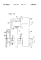
- FIGS. 7A-7C are schematic diagrams illustrating the sequence of operation of the apparatus to load and unload a wafer cassette from the box.
- FIGS. 8A-8B are schematic diagrams illustrating the sequence of operation of the apparatus to close the box.
- box handling apparatus of the present invention is shown to comprise a base, generally indicated at 10, adapted to rest on the floor and support the other components of the apparatus.
- the base 10 includes a top 11.
- An extensible and retractable tower, indicated generally at 12, is mounted on the base 10 and projects upwardly from the base.
- Controls, generally indicated at 15, are mounted on the top 11 generally at the rear of the apparatus.
- a box B such as a box of the type for holding semiconductor wafers (not shown), may be placed in a entry station indicated generally at 14 at the right end (in the orientation of the apparatus shown in FIG. 1) of the base 10.
- the apparatus moves the box B to a central load/unload station 16 and thence to an offload station 18 (both number designating their subjects generally) on the left end of the base 10, where the box is removed from the apparatus.
- the box B includes lid L and a bottom M which are constructed for snap-latching interengagement.
- An example of such a box is the ULTRAPAK box made by Empak, Inc. of Colorado Springs, Colo.
- a box opening assembly is supported at the upper end of the tower 12 above the central station 16 for movement with the tower as described more fully hereinafter.
- a pair of cassette gripping arms 22 are mounted for conjoint pivoting motion on the base 10 to remove and replace a wafer cassette C (FIG. 7B) in the box B.
- the apparatus is shown to comprise three platforms (broadly, "supports") including an entry platform 26 located at the entry station 14, a center platform 28 located at the central load/unload station 16, and an exit platform 30 located at the offload station 18.
- the center platform 28 has four locating pins 32 arranged in a rectangle for precisely locating the box B on that platform.
- the center platform 28 also has eight suction cups 34 arranged for applying vacuum pressure to the bottom M of the box B for holding the bottom of the box down on the center platform.
- Each platform is mounted on the base 10 by a corresponding pneumatic platform cylinder (designated 36, 38, 40, respectively) so that the platform can be raised and lowered.
- the platform cylinders 36, 40 associated with the entry and exit platforms 26, 28 are fixedly mounted on the base top 11.
- the center platform cylinder 38 is differently mounted to allow for additional movement of the center platform 28 necessary to open and close the box B as described hereinafter.
- the box B is transported between the stations by a walking beam mechanism which includes a pair of rails 44 extending from the entry station 14 to the exit station 18.
- a box carriage, generally indicated at 46 includes four trucks 48, each mounted on a respective one of the rails 44 for sliding movement lengthwise of the rail. As shown in FIG. 2, two of the trucks 48 are mounted on each rail 44 laterally opposite the trucks mounted on the other rail.
- the trucks 48 on each rail 44 are connected together by respective longitudinal connector plates 50, and the longitudinal connector plates are joined to each other by lateral connector plates 52 located at the ends of the carriage 46.
- the longitudinal connector plates 52 each extend from below the base top 11 through elongate openings 53 to above the top.
- the lateral connector plates 52 are attached at the bottom of the longitudinal connector plates 50 and are located below the entry platform cylinder 36 and the exit platform cylinder 40. Thus, the trucks 48 and longitudinal connector plates 50 are interconnected to move conjointly along the rails 44 between the ends of the base 10.
- the carriage 46 is constructed to support the box B at two locations on the carriage.
- Two pairs of laterally opposing support tabs 54 are mounted on the longitudinal connector plates 50 at a first of the locations, shown at the exit station 18 in FIG. 2.
- Another two pairs of laterally opposing support tabs 54 are mounted on the longitudinal connector plates 50 at a second of the locations, shown at the center station in FIG. 2. All of the support tabs 54 project inwardly from the respective longitudinal connector plate 50 to which they are connected and lie substantially in the same plane.
- the platform cylinders 36, 38, 40 are capable of moving the platforms 26, 28, 30 above the plane of the support tabs 54 to lift a box B off of the support tabs (and hence off of the carriage 46), and capable of moving the platforms below the plane of the tabs to set the box on the support tabs.
- the box B moves with the carriage 46 when it rests on the support tabs 54 and does not move with the carriage when supported by any one of the platforms.
- the carriage 46 is moved by a rodless carriage cylinder 58 mounted on the apparatus between the position shown in FIG. 2, and a position in which the set of support tabs 54 is located at the central load/unload station 16 and the set of tabs is located at the exit station 18. More specifically, the carriage cylinder 58 is mounted at its ends by brackets 60 to a table top 11 of the base 10. The top 11 has been broken away to show the carriage cylinder 58 in FIG. 2. A slide 62 of the carriage cylinder 58 is connected to the forward longitudinal connector plate 50 of the carriage 46 (FIG. 2). Shock absorbers (not shown) are mounted on the ends of the carriage 46 to achieve a soft stop of the carriage at each end of its travel.
- the box B is held against lateral movement on the carriage 46 and on the platforms 26, 28, 30 by a pair of guides 66 extending from end to end of the base 10 above the platforms and carriage.
- the guides are mounted at each end by stanchions 67 mounted on the top 11 of the base 10.
- the guides 66 including lateral members 66A which are slidably connected to the stanchions 67, and permit adjustment of the lateral spacing of the guides. It may be seen in FIG. 3, that the platforms 26, 28, 30 and carriage 46 are mounted at an angle to the horizontal (i.e., tilted downwardly toward the front of the apparatus). The tilt gravitationally biases the semiconductor wafers W in the box B toward one side of the box.
- the sensor 68 is a photoelectric eye mounted on the rear guide 66 and looking forward and downward through an open central portion of the corresponding platform. Light emitted from the eye 68 is reflected by a reflector 70 mounted on the underside of the platform when there is no box at the particular station (14, 16 or 18). However when a box is present in the station in the proper orientation, it blocks the light from the reflector 70 causing a signal from the sensor 68 that a box is present. The vacuum pressure applied through the suction cups 34 is monitored to determine whether the box B is located in the proper orientation in the central station 16.
- the center platform cylinder 38 is mounted in a channel 71 connected by a pair of joining members 72 to a slide plate 73.
- a pair of trucks 74 riding on a rail 75 mount the slide plate 73 for generally vertical motion on the apparatus.
- the slide plate 73 is also connected to a slide 76 of a rodless box lift cylinder 78 mounted in a lower portion 79 of the extensible and retractable tower 12.
- the lower portion 79 of the tower is fixedly mounted on the base 10 and does not move relative to the base.
- the box lift cylinder 78 is operable to move the center platform 28 from a lowered position (FIG. 3) to a raised position (FIG. 7B) in which the box B is received in the box opening assembly 20.
- An upper portion 80 of the tower 12 telescopingly receives the lower portion 79 of the tower for generally vertical sliding motion relative to the lower portion and base 10.
- a rodless lid lift cylinder 81 is also fixedly mounted on the lower portion 79 of the tower 12.
- the lid lift cylinder 81 has a slide 82 which is connected to a joining member 83 connecting the slide 82 to the upper portion 80.
- the joining member 83 is also connected to trucks 84 slidingly mounted on a track 85 to guide the motion of the joining member to move the upper portion between a lowered position (shown in FIG. 3) to a raised position for lifting the lid L off of the bottom M of the box B as described hereinafter.
- the box opening assembly 20 includes a housing 88 mounted on the upper portion 80 of the tower 12 and extending in cantilever fashion forwardly over the center platform 28 of the apparatus.
- the box opening assembly 20 includes four upper lid locators 90 (only two are shown) mounted on the underside of the housing 88 for receiving the top corners of the lid L.
- the upper and lower lid locators 90, 92 precisely locate the lid L in the box opening assembly 20.
- the upper and lower lid locators 90, 92 engage the lid L when the box lift cylinder 78 is activated to raise the center platform 28 and box B.
- opposing box opening units each include a lid manipulating arm (generally indicated at 94) pivotally mounted on the housing 88 and a finger 96 pivotally mounted on the arm.
- the arm 94 is covered by a shield 97 (FIG. 1) which is broken away or removed in the other drawings.
- the finger 96 has a tip 96A at its free end.
- the arm 94 is actuated by a pair of swing cylinders (designated 98 and 100, respectively) arranged to operate in series in the housing 88 so that each arm has three positions (FIG. 5).
- a first of the swing cylinders 98 in series is fixedly mounted by a bracket 101 on the housing 88 and has a rod 102 connected to a second of the swing cylinders 100 mounted on the housing for movement lengthwise of the cylinder.
- the second swing cylinder 100 is slidingly mounted on the housing 88 and includes a rod 104 which is connected to an upper end of the arm 94, above its pivot point P1.
- the second swing cylinder 100 is able to slide with respect to the housing to transmit the motion of the rod 102 to the arm 94. Extension of the rods 102, 104 from both swing cylinders 98, 100 moves the free end of the arm to its inwardmost position.
- the lid manipulating arms 94 each carry a finger cylinder 106 which moves with the arm.
- the finger cylinder 106 has a rod 108 which is connected to the finger 96 for swinging the finger through approximately a 90° angle about pivot point P2 for use in unlatching the lid L from the bottom M of the box B, as described hereinafter.
- the lid lift cylinder 81 extends the upper portion 80 of the tower 12 to raise the lid above the bottom, exposing the wafer cassette C contained in the box B.
- a purge gas delivery unit 110 is mounted on the forward end of the housing 88 and arranged for directing purge gas into the lid L when it is separated from the box B.
- the cassette gripping arms 22 are capable of removing the cassette C from the bottom M of the box B, moving it to a location where the cassette can be loaded or unloaded, and returning the cassette back into the bottom.
- the gripping arms 22 are each mounted on a splined shaft 114 for conjoint pivoting with the shaft about its longitudinal axis.
- the gripping arms 22 may slide longitudinally of the shaft 114 for gripping and releasing the cassette C.
- each gripping arm 22 There is a cassette grip cylinder 116 for each gripping arm 22 which has a rod 116A joined by a yoke 118 to collar 120 connected to the gripping arm for sliding the arm between a release position in which the gripping arms 22 are spaced farther apart and a gripping position in which the arms are spaced more closely and grip the cassette C.
- the shaft 114 and cylinders 116 are substantially enclosed by a cover 119, which has been removed in FIG. 2.
- the free end of each gripping arm 22 has a bracket 121 which is specially shaped for engaging and holding the cassette C of the particular type of box being opened.
- the splined shaft 114 is journalled in a bearing 122 at each end for rotation about the longitudinal axis of the shaft.
- the cylinders 116 are connected by respective brackets 116B to the bearing 122.
- the splined shaft 114 has a gear 124 fixedly mounted on the shaft in its center. As shown in FIG. 3, a toothed belt 126 is received around the gear 124 and extends down to a lower free wheeling gear 128 mounted on the base 10 below gear 124.
- the rotation of the splined shaft 114 and pivoting of the cassette gripping arms 22 is actuated by a pneumatic gripping arm pivot cylinder 130 mounted on a vertical member 132 of the base 10.
- a rod 134 of the pivot cylinder 132 is connected to a clamp unit 136 which is connected to the belt 126. Extension of the rod from its position shown in FIG. 3 causes counterclockwise rotation of the splined shaft 114 and pivoting of the gripping arms 22 forwardly away from the box opening assembly 20. From the extended position, retraction of the rod 134 causes clockwise rotation of the shaft 114 and swing the gripping arms 22 back to the position shown in FIG. 3.
- Closing of the lid L on the bottom M of the box B is accomplished using the center platform 28, center platform cylinder 38 and four extensible and retractable stops 140 mounted on the housing 88 inside the four lid corner guides 90.
- the stops are retracted and do not engage the lid L.
- the stops 140 are extended to apply equal pressure to the corners of the lid.
- the stops 140 each comprise a generally vertically arranged pneumatic stop cylinder 142 which is extensible to lower the stops and retractable to raise the stops.
- FIGS. 6-8 For purposes of the present description, operation of the apparatus to load semiconductor wafers into a cassette C will be described. However, it is to be understood that unloading of the wafers can be accomplished with the apparatus of the present invention.
- the operation is controlled by a programmable logic circuit (not shown), such as a conventional microprocessor of the type used to control process machinery.
- An empty box B is first placed at the entry station 14 on the entry platform 26 which is raised by the platform cylinder 36 above the carriage 46 for supporting the box off of the carriage.
- the box will remain supported by the entry platform 26 until such time as the carriage 46 is cycled to return to a position where four of the support tabs 54 are located at the entry station 14.
- the box lift cylinder 78 is actuated to lower the entry platform 26 so that the box B rests upon the support tabs 54 of the carriage 46.
- the carriage cylinder 58 is activated to slide the carriage 46 on the rails 44 for bringing the box into the central station 16.
- the box lift cylinder 78 moves the center platform 28 up between the support tabs 54 to raise the box B off of the carriage 46 and up into the box opening assembly 20 (FIG. 6A).
- the operation of only one of the arms 9A is illustrated in FIGS. 6A-6C, the operation of the other being identical.
- the cassette gripping arms 22 are in their release positions and the lid manipulating arms 94 have been pivoted to their full outward positions so that there are no obstructions for the box as it moves into the box opening assembly 20.
- the top and bottom corners of the lid L are received in the upper and lower lid locators 90, 92 so that the lid is precisely positioned in the box opening assembly 20.
- the finger cylinders 106 carried by the lid manipulating arms 94 are extended, causing the fingers 96 to pivot upwardly so that the tips 96A move under the lid L.
- the fingers 96 continue to pivot so that the tips 96A deflect the lid L outwardly on opposite sides.
- the tips 96A engage the lid L the finger 96 below the tip engages the bottom M, deflecting it inwardly. In this way the finger 96 wedges apart the lid L from the bottom M to unlatch the lid from the bottom.
- the lid lift cylinder 81 is activated to raise the upper portion 80 of the tower 12, carrying the box opening assembly 20 and the lid L held thereby upwardly to separate the lid from the bottom M (FIG. 6C).
- the vacuum pressure applied by the suction cups 34 to the bottom of the box holds the bottom from being pulled upward by virtue of residual engagement with the lid L.
- Low pressure purge gas from the purge gas delivery unit 110 floods the lid L so that particulates and moisture are kept off interior surfaces of the lid after it separates from the bottom M.
- the grip cylinders 116 are activated to concurrently move the cassette gripping arms 22 toward each other to grip the cassette C which projects above the upper edge of the bottom M of the box B (FIG. 7A).
- the brackets 121 on the ends of the gripping arms 22 have slots which receive protruding portions of the cassette C so that the cassette is held securely by the arms.
- the box lift cylinder 78 is activated to lower the center platform 28 and the bottom M, so that the cassette C is now supported solely by the gripping arms 22. After the bottom M is lowered and fully clear of the cassette C, the pivot cylinder 130 extends its rod 134 to rotate the splined shaft 114 counterclockwise.
- the gripping arms 22 and the cassette C held by the arms swing conjointly with the shaft 114 so that the cassette is brought to a load/unload position (FIG. 7B).
- the cassette C has been moved from an orientation in which it opens upwardly to an orientation where the cassette opens forwardly for receiving semiconductor wafers.
- the box lift and lid lift cylinders 78, 84 are activated to move the bottom M up and the lid L down to a closed position, as illustrated in FIG. 7B. However, the lid does not latch onto the bottom at this time.
- the wafers can be loaded into the cassette C manually, or by commercially available wafer loading apparatus (not shown) in the load/unload position.
- the wafers are loaded in respective slots (not shown) of the cassette C so that their unfinished (bottom) sides face downwardly and engage the dividers which define the slots.
- the downward tilt of the platforms 26, 28, 30 and carriage 46 toward the front of the apparatus causes the unfinished sides of the wafers to engage the dividers rather than the finished sides when the cassette C is replaced in the box B.
- a signal indicative of the loaded condition of the cassette is sent to the box handling apparatus.
- the signal may be manually input or automatically sent by the loading machinery to the apparatus.
- the box lift and lid lift cylinders 78, 84 are activated to raise the lid L and lower the bottom M, providing space for the cassette C.
- the pivot cylinder 130 then pivots the gripping arms 22 so that the cassette C is moved back to a position over the center platform 28 (FIG. 7C).
- the bottom M of the box B is lifted up by the box lift cylinder 78 from the position shown in FIG. 7C so that the cassette C is again supported by the bottom as shown in FIG. 7A.
- the grip cylinders 116 then retract to move the gripping arms 22 out to their release position, releasing their grip on the cassette C.
- the center platform cylinder 38 is retracted so that the bottom M and cassette C are dropped down a short distance (e.g., 1 inch).
- the lid lift cylinder 81 moves the box opening assembly 20 downward to the bottom M of the box B.
- the lid L is still slightly above the bottom (FIG. 8A).
- the finger cylinders 106 are activated to pivot the fingers 96 downwardly to a position in which the tips 96A are substantially under the lid L and the first arm swing cylinders 98 are also retracted so that the fingers deflect the lid outwardly slightly.
- the stop cylinders 142 now lock the stops 140 in position for engaging the lid L at the corners.
- the center platform cylinder 38 moves the bottom M upwardly so that it lifts the lid off of the fingers 96.
- the lid manipulating arms 94 continue to pivot to their fully outward position out of the way of the box B.
- the bottom M and lid L continue upwardly until the lid engages the four stops 140 which hold the lid so that the bottom is now forced to move upwardly within the lid.
- the bottom is forced into the lid so that the lid may snap-latch onto the bottom.
- the center platform 28 and the stops 140 help to assure equal pressure distribution over the lid L and bottom M for sealing, latching connection around the entire joint.
- the lid manipulating arms 94 are also pivoted to their full inward position to push against the sides of the lid L to facilitate latching.
- the closed box B is deposited on the support tabs 54 of the carriage 46 by downward movement of the center platform 28 by operation of the box lift cylinder 78.
- the carriage cylinder 58 is activated to move the box to the offload station 18, and the offload platform 30 is actuated to pick the box off of the carriage 46.
- the carriage is free to move back to a position for moving a new box into the central load/unload station 16. It will be understood that movement of the carriage 46 to bring the box B to the offload station 18 can simultaneously bring a new box into the central load/unload station 16. As soon as both the loaded box and the new, empty box are lifted off of the carriage 46, the carriage is sent back to its position shown in FIG. 2. It is to be understood that the precise box opening and closing sequences may be other than described without departing from the scope of the present invention.
- the box opening assembly 20 is moved upwardly with the lid as before to open the box.
- the box opening assembly is moved downwardly close to the bottom M, which, as above, has been dropped down slightly by the center platform cylinder 38.
- the bottom is then raised by the center platform cylinder 38 and lifts the lid off of the fingers 96 (and into engagement with the stops).
- the arms 94 swing to their full outward position.
Landscapes
- Engineering & Computer Science (AREA)
- Mechanical Engineering (AREA)
- Physics & Mathematics (AREA)
- Condensed Matter Physics & Semiconductors (AREA)
- General Physics & Mathematics (AREA)
- Manufacturing & Machinery (AREA)
- Computer Hardware Design (AREA)
- Microelectronics & Electronic Packaging (AREA)
- Power Engineering (AREA)
- Robotics (AREA)
- Container, Conveyance, Adherence, Positioning, Of Wafer (AREA)
Abstract
Description
Claims (13)
Priority Applications (1)
| Application Number | Priority Date | Filing Date | Title |
|---|---|---|---|
| US08/891,529 US5894711A (en) | 1997-07-11 | 1997-07-11 | Box handling apparatus and method |
Applications Claiming Priority (1)
| Application Number | Priority Date | Filing Date | Title |
|---|---|---|---|
| US08/891,529 US5894711A (en) | 1997-07-11 | 1997-07-11 | Box handling apparatus and method |
Publications (1)
| Publication Number | Publication Date |
|---|---|
| US5894711A true US5894711A (en) | 1999-04-20 |
Family
ID=25398353
Family Applications (1)
| Application Number | Title | Priority Date | Filing Date |
|---|---|---|---|
| US08/891,529 Expired - Fee Related US5894711A (en) | 1997-07-11 | 1997-07-11 | Box handling apparatus and method |
Country Status (1)
| Country | Link |
|---|---|
| US (1) | US5894711A (en) |
Cited By (7)
| Publication number | Priority date | Publication date | Assignee | Title |
|---|---|---|---|---|
| US6216421B1 (en) * | 1999-07-01 | 2001-04-17 | H-Square Corporation | Device for seating and unseating a lid from a carrying cassette |
| WO2002058995A1 (en) * | 2001-01-26 | 2002-08-01 | Tekcel, Inc. | Microplate lidder/delidder |
| WO2002092481A1 (en) * | 2001-05-14 | 2002-11-21 | F.R. Drake Company | System and method of processing and packing disk-like objects |
| US6604337B2 (en) * | 2001-05-30 | 2003-08-12 | The United States Of America As Represented By The United States Postal Service | Automatic lidder and/or un-lidder system and method |
| US20080000074A1 (en) * | 2006-05-05 | 2008-01-03 | Genaro Martinez | Computer automated tag test system |
| US11014700B2 (en) * | 2018-05-08 | 2021-05-25 | Multivac Sepp Haggenmueller Se & Co. Kg | Packaging machine with compensation cylinder |
| IT202200023451A1 (en) * | 2022-11-14 | 2024-05-14 | Meridionale Impianti Spa | SEMICONDUCTOR WAFER CONTAINMENT BOX HANDLING DEVICE |
Citations (22)
| Publication number | Priority date | Publication date | Assignee | Title |
|---|---|---|---|---|
| US3261144A (en) * | 1962-01-31 | 1966-07-19 | Reynolds Metals Co | Apparatus for crimping a cover to an open end of a container or the like |
| US3545163A (en) * | 1969-07-30 | 1970-12-08 | Mahaffy & Harder Eng Co | Package forming methods and apparatus |
| US3561190A (en) * | 1969-09-15 | 1971-02-09 | Stapling Machines Co | Carton taping machine |
| US3704568A (en) * | 1970-10-16 | 1972-12-05 | Struers Chemiske Lab H | Apparatus for the filling of petri dishes |
| US3894379A (en) * | 1971-02-22 | 1975-07-15 | Continental Can Co | Method of closing a flexible container |
| US4091919A (en) * | 1976-09-07 | 1978-05-30 | Monsanto | Wafer packaging system |
| US4129211A (en) * | 1976-09-07 | 1978-12-12 | Monsanto Company | Wafer packaging system |
| US4170861A (en) * | 1978-04-07 | 1979-10-16 | New Brunswick Scientific Co., Inc. | Method and apparatus for filling petri dishes |
| US4171740A (en) * | 1976-09-07 | 1979-10-23 | Monsanto Company | Wafer packaging system |
| US4461136A (en) * | 1981-12-30 | 1984-07-24 | Quachita Machine Works, Inc. | Method and apparatus for enveloping a plurality of items in a stretchable film |
| US4592189A (en) * | 1983-10-28 | 1986-06-03 | Martini Phillip J | Apparatus for closing and sealing telescoping boxes |
| US5077956A (en) * | 1989-08-02 | 1992-01-07 | Newtec International (Societe Anonyme) | Method for banding a palletized load |
| US5129211A (en) * | 1987-01-02 | 1992-07-14 | Andersson Claes Goeran | Method and an arrangement for the manufacture of a pack consisting of a banderole-like pack sleeve |
| US5184996A (en) * | 1991-08-26 | 1993-02-09 | Gasdorf Tool & Machine Co., Inc. | Carton assembly machine for assembling a base and a cover |
| US5351415A (en) * | 1992-05-18 | 1994-10-04 | Convey, Inc. | Method and apparatus for maintaining clean articles |
| US5369939A (en) * | 1993-03-23 | 1994-12-06 | Moen Industries, Inc. | High speed lidder |
| US5419096A (en) * | 1993-07-28 | 1995-05-30 | World Class Packaging Systems, Inc. | Packaging method and apparatus for packaging large meat products in a desired gaseous atmosphere |
| US5473860A (en) * | 1991-09-03 | 1995-12-12 | Norden Pac Development Ab | Method and apparatus for manufacturing a container filled with a product |
| US5534282A (en) * | 1989-08-30 | 1996-07-09 | Seawell North America Inc. | Packing perishable goods |
| US5551210A (en) * | 1995-03-31 | 1996-09-03 | Williamson; Robert L. | Machine for packaging product |
| US5657617A (en) * | 1996-01-25 | 1997-08-19 | Komag, Incorporated | Shipping cassette lid and unlid automation |
| US5701722A (en) * | 1996-01-19 | 1997-12-30 | Hk Systems, Inc. | Apparatus and method for palletizing and wrapping a load |
-
1997
- 1997-07-11 US US08/891,529 patent/US5894711A/en not_active Expired - Fee Related
Patent Citations (22)
| Publication number | Priority date | Publication date | Assignee | Title |
|---|---|---|---|---|
| US3261144A (en) * | 1962-01-31 | 1966-07-19 | Reynolds Metals Co | Apparatus for crimping a cover to an open end of a container or the like |
| US3545163A (en) * | 1969-07-30 | 1970-12-08 | Mahaffy & Harder Eng Co | Package forming methods and apparatus |
| US3561190A (en) * | 1969-09-15 | 1971-02-09 | Stapling Machines Co | Carton taping machine |
| US3704568A (en) * | 1970-10-16 | 1972-12-05 | Struers Chemiske Lab H | Apparatus for the filling of petri dishes |
| US3894379A (en) * | 1971-02-22 | 1975-07-15 | Continental Can Co | Method of closing a flexible container |
| US4091919A (en) * | 1976-09-07 | 1978-05-30 | Monsanto | Wafer packaging system |
| US4129211A (en) * | 1976-09-07 | 1978-12-12 | Monsanto Company | Wafer packaging system |
| US4171740A (en) * | 1976-09-07 | 1979-10-23 | Monsanto Company | Wafer packaging system |
| US4170861A (en) * | 1978-04-07 | 1979-10-16 | New Brunswick Scientific Co., Inc. | Method and apparatus for filling petri dishes |
| US4461136A (en) * | 1981-12-30 | 1984-07-24 | Quachita Machine Works, Inc. | Method and apparatus for enveloping a plurality of items in a stretchable film |
| US4592189A (en) * | 1983-10-28 | 1986-06-03 | Martini Phillip J | Apparatus for closing and sealing telescoping boxes |
| US5129211A (en) * | 1987-01-02 | 1992-07-14 | Andersson Claes Goeran | Method and an arrangement for the manufacture of a pack consisting of a banderole-like pack sleeve |
| US5077956A (en) * | 1989-08-02 | 1992-01-07 | Newtec International (Societe Anonyme) | Method for banding a palletized load |
| US5534282A (en) * | 1989-08-30 | 1996-07-09 | Seawell North America Inc. | Packing perishable goods |
| US5184996A (en) * | 1991-08-26 | 1993-02-09 | Gasdorf Tool & Machine Co., Inc. | Carton assembly machine for assembling a base and a cover |
| US5473860A (en) * | 1991-09-03 | 1995-12-12 | Norden Pac Development Ab | Method and apparatus for manufacturing a container filled with a product |
| US5351415A (en) * | 1992-05-18 | 1994-10-04 | Convey, Inc. | Method and apparatus for maintaining clean articles |
| US5369939A (en) * | 1993-03-23 | 1994-12-06 | Moen Industries, Inc. | High speed lidder |
| US5419096A (en) * | 1993-07-28 | 1995-05-30 | World Class Packaging Systems, Inc. | Packaging method and apparatus for packaging large meat products in a desired gaseous atmosphere |
| US5551210A (en) * | 1995-03-31 | 1996-09-03 | Williamson; Robert L. | Machine for packaging product |
| US5701722A (en) * | 1996-01-19 | 1997-12-30 | Hk Systems, Inc. | Apparatus and method for palletizing and wrapping a load |
| US5657617A (en) * | 1996-01-25 | 1997-08-19 | Komag, Incorporated | Shipping cassette lid and unlid automation |
Cited By (13)
| Publication number | Priority date | Publication date | Assignee | Title |
|---|---|---|---|---|
| US6216421B1 (en) * | 1999-07-01 | 2001-04-17 | H-Square Corporation | Device for seating and unseating a lid from a carrying cassette |
| WO2002058995A1 (en) * | 2001-01-26 | 2002-08-01 | Tekcel, Inc. | Microplate lidder/delidder |
| US6543203B2 (en) * | 2001-01-26 | 2003-04-08 | Tekcel, Inc. | Microplate lidder/delidder |
| US7028450B2 (en) | 2001-05-14 | 2006-04-18 | F.R. Drake Company | System and method of processing and packing disk-like objects |
| WO2002092481A1 (en) * | 2001-05-14 | 2002-11-21 | F.R. Drake Company | System and method of processing and packing disk-like objects |
| US20060283150A1 (en) * | 2001-05-14 | 2006-12-21 | Hart Colin R | System and method of processing and packing disk-like objects |
| US6918736B2 (en) | 2001-05-14 | 2005-07-19 | F.R. Drake Company | Method and apparatus for stacking discrete planar objects |
| US7021033B2 (en) | 2001-05-30 | 2006-04-04 | United States Postal Service | Container strap cutting method |
| US6604337B2 (en) * | 2001-05-30 | 2003-08-12 | The United States Of America As Represented By The United States Postal Service | Automatic lidder and/or un-lidder system and method |
| US20080000074A1 (en) * | 2006-05-05 | 2008-01-03 | Genaro Martinez | Computer automated tag test system |
| US8010219B2 (en) * | 2006-05-05 | 2011-08-30 | Tc License, Ltd. | Computer automated test and processing system of RFID tags |
| US11014700B2 (en) * | 2018-05-08 | 2021-05-25 | Multivac Sepp Haggenmueller Se & Co. Kg | Packaging machine with compensation cylinder |
| IT202200023451A1 (en) * | 2022-11-14 | 2024-05-14 | Meridionale Impianti Spa | SEMICONDUCTOR WAFER CONTAINMENT BOX HANDLING DEVICE |
Similar Documents
| Publication | Publication Date | Title |
|---|---|---|
| JP4642218B2 (en) | Loading and unloading stations for semiconductor processing equipment | |
| JP4729237B2 (en) | Material transport system or method, carry-in port module | |
| US4802809A (en) | Manipulator for standard mechanical interface apparatus | |
| US4907701A (en) | Apparatus for inspecting the appearance of semiconductor devices | |
| US6086323A (en) | Method for supplying wafers to an IC manufacturing process | |
| KR101265182B1 (en) | Cleaner for wafer container | |
| CN113950453B (en) | Storage system | |
| JP5020994B2 (en) | Loading and unloading stations for semiconductor processing equipment | |
| US7153083B2 (en) | Material handling and transport process | |
| US4934767A (en) | Semiconductor wafer carrier input/output drawer | |
| US5894711A (en) | Box handling apparatus and method | |
| JP4543567B2 (en) | Stocker robot | |
| US11460766B2 (en) | Article storage facility | |
| US20080019811A1 (en) | Method and apparatus for vertical wafer transport, buffer and storage | |
| KR20210134498A (en) | Transfer facility and method for transferring container | |
| GB2310537A (en) | Automatically removing a wafer carrier from a container | |
| JP2003309163A (en) | Unmanned carrier system | |
| US20250042677A1 (en) | Palletizer | |
| JP7413756B2 (en) | Transfer equipment | |
| JP7228759B2 (en) | Load port and load port FOUP lid abnormality detection method | |
| JP3887837B2 (en) | Closed container opening and closing system | |
| JPH07323905A (en) | Carrying device | |
| US20210375653A1 (en) | Apparatus and methods for automatically handling die carriers | |
| JP2835869B2 (en) | Transport equipment | |
| CN119317580A (en) | Access Station |
Legal Events
| Date | Code | Title | Description |
|---|---|---|---|
| AS | Assignment |
Owner name: MEMC ELECTRONIC MATERIALS, INC., MISSOURI Free format text: ASSIGNMENT OF ASSIGNORS INTEREST;ASSIGNORS:LENK, JAMES C.;SHIVE, LARRY W.;ANDERSON, GARY L.;REEL/FRAME:009594/0876 Effective date: 19981113 |
|
| CC | Certificate of correction | ||
| AS | Assignment |
Owner name: MEMC ELECTRONIC MATERIALS, INC., MISSOURI Free format text: TERMINATION OF SECURITY INTEREST;ASSIGNOR:E.ON AG;REEL/FRAME:012263/0944 Effective date: 20011113 Owner name: CITICORP USA, INC., DELAWARE Free format text: SECURITY INTEREST;ASSIGNORS:MEMC PASADENA, INC.;PLASMASIL, L.L.C.;SIBOND, L.L.C.;AND OTHERS;REEL/FRAME:012273/0145 Effective date: 20011113 Owner name: CITICORP USA, INC., DELAWARE Free format text: SECURITY AGREEMENT;ASSIGNORS:MEMC PASADENA, INC.;PLASMASIL, L.L.C.;SIBOND, L.L.C.;AND OTHERS;REEL/FRAME:012280/0161 Effective date: 20011113 |
|
| AS | Assignment |
Owner name: E. ON AG, GERMANY Free format text: SECURITY INTEREST;ASSIGNOR:MEMC ELECTRONIC MATERIALS, INC.;REEL/FRAME:012407/0806 Effective date: 20011025 |
|
| AS | Assignment |
Owner name: CITICORP USA, INC., DELAWARE Free format text: SECURITY AGREEMENT;ASSIGNORS:MEMC PASADENA, INC.;PLASMASIL, L.L.C.;SIBOND, L.L.C.;AND OTHERS;REEL/FRAME:012365/0345 Effective date: 20011221 |
|
| REMI | Maintenance fee reminder mailed | ||
| AS | Assignment |
Owner name: CITICORP USA, INC., DELAWARE Free format text: SECURITY AGREEMENT;ASSIGNORS:MEMC ELECTRONIC MATERIALS, INC.;MEMC PASADENA, INC.;PLASMASIL, L.L.C.;AND OTHERS;REEL/FRAME:013964/0378;SIGNING DATES FROM 20020303 TO 20030303 Owner name: CITICORP USA, INC., DELAWARE Free format text: SECURITY AGREEMENT;ASSIGNORS:MEMC ELECTRONIC MATERIALS, INC.;MEMC PASADENA, INC.;PLASMASIL, L.L.C.;AND OTHERS;SIGNING DATES FROM 20020303 TO 20030303;REEL/FRAME:013964/0378 |
|
| LAPS | Lapse for failure to pay maintenance fees | ||
| STCH | Information on status: patent discontinuation |
Free format text: PATENT EXPIRED DUE TO NONPAYMENT OF MAINTENANCE FEES UNDER 37 CFR 1.362 |
|
| FP | Lapsed due to failure to pay maintenance fee |
Effective date: 20030420 |
|
| AS | Assignment |
Owner name: MEMC ELECTRONIC MATERIALS, INC., MISSOURI Free format text: RELEASE OF SECURITY INTEREST;ASSIGNOR:CITICORP USA, INC.;REEL/FRAME:016641/0045 Effective date: 20050602 |
|
| AS | Assignment |
Owner name: MEMC ELECTRONIC MATERIALS, INC. (NOW KNOWN AS SUNE Free format text: RELEASE OF SECURITY INTEREST TO REEL/FRAME: 012280/0161;ASSIGNOR:CITICORP USA, INC.;REEL/FRAME:032458/0794 Effective date: 20140313 Owner name: PLASMASIL, L.L.C., MISSOURI Free format text: RELEASE OF SECURITY INTEREST TO REEL/FRAME: 012280/0161;ASSIGNOR:CITICORP USA, INC.;REEL/FRAME:032458/0794 Effective date: 20140313 Owner name: SIBOND, L.L.C., MISSOURI Free format text: RELEASE OF SECURITY INTEREST TO REEL/FRAME: 012280/0161;ASSIGNOR:CITICORP USA, INC.;REEL/FRAME:032458/0794 Effective date: 20140313 Owner name: MEMC SOUTHWEST INC., MISSOURI Free format text: RELEASE OF SECURITY INTEREST TO REEL/FRAME: 012280/0161;ASSIGNOR:CITICORP USA, INC.;REEL/FRAME:032458/0794 Effective date: 20140313 Owner name: MEMC PASADENA, INC., TEXAS Free format text: RELEASE OF SECURITY INTEREST TO REEL/FRAME: 012280/0161;ASSIGNOR:CITICORP USA, INC.;REEL/FRAME:032458/0794 Effective date: 20140313 Owner name: MEMC INTERNATIONAL, INC. (NOW KNOWN AS SUNEDISON I Free format text: RELEASE OF SECURITY INTEREST TO REEL/FRAME: 012280/0161;ASSIGNOR:CITICORP USA, INC.;REEL/FRAME:032458/0794 Effective date: 20140313 |