US5884791A - Telescopic jib for vehicular cranes - Google Patents
Telescopic jib for vehicular cranes Download PDFInfo
- Publication number
- US5884791A US5884791A US08/878,100 US87810097A US5884791A US 5884791 A US5884791 A US 5884791A US 87810097 A US87810097 A US 87810097A US 5884791 A US5884791 A US 5884791A
- Authority
- US
- United States
- Prior art keywords
- telescopic
- lower section
- jib
- telescopic jib
- section part
- Prior art date
- Legal status (The legal status is an assumption and is not a legal conclusion. Google has not performed a legal analysis and makes no representation as to the accuracy of the status listed.)
- Expired - Lifetime
Links
Images


Classifications
-
- B—PERFORMING OPERATIONS; TRANSPORTING
- B66—HOISTING; LIFTING; HAULING
- B66C—CRANES; LOAD-ENGAGING ELEMENTS OR DEVICES FOR CRANES, CAPSTANS, WINCHES, OR TACKLES
- B66C23/00—Cranes comprising essentially a beam, boom, or triangular structure acting as a cantilever and mounted for translatory of swinging movements in vertical or horizontal planes or a combination of such movements, e.g. jib-cranes, derricks, tower cranes
- B66C23/18—Cranes comprising essentially a beam, boom, or triangular structure acting as a cantilever and mounted for translatory of swinging movements in vertical or horizontal planes or a combination of such movements, e.g. jib-cranes, derricks, tower cranes specially adapted for use in particular purposes
- B66C23/36—Cranes comprising essentially a beam, boom, or triangular structure acting as a cantilever and mounted for translatory of swinging movements in vertical or horizontal planes or a combination of such movements, e.g. jib-cranes, derricks, tower cranes specially adapted for use in particular purposes mounted on road or rail vehicles; Manually-movable jib-cranes for use in workshops; Floating cranes
- B66C23/42—Cranes comprising essentially a beam, boom, or triangular structure acting as a cantilever and mounted for translatory of swinging movements in vertical or horizontal planes or a combination of such movements, e.g. jib-cranes, derricks, tower cranes specially adapted for use in particular purposes mounted on road or rail vehicles; Manually-movable jib-cranes for use in workshops; Floating cranes with jibs of adjustable configuration, e.g. foldable
-
- B—PERFORMING OPERATIONS; TRANSPORTING
- B66—HOISTING; LIFTING; HAULING
- B66C—CRANES; LOAD-ENGAGING ELEMENTS OR DEVICES FOR CRANES, CAPSTANS, WINCHES, OR TACKLES
- B66C23/00—Cranes comprising essentially a beam, boom, or triangular structure acting as a cantilever and mounted for translatory of swinging movements in vertical or horizontal planes or a combination of such movements, e.g. jib-cranes, derricks, tower cranes
- B66C23/62—Constructional features or details
- B66C23/64—Jibs
- B66C23/70—Jibs constructed of sections adapted to be assembled to form jibs or various lengths
- B66C23/701—Jibs constructed of sections adapted to be assembled to form jibs or various lengths telescopic
-
- B—PERFORMING OPERATIONS; TRANSPORTING
- B66—HOISTING; LIFTING; HAULING
- B66C—CRANES; LOAD-ENGAGING ELEMENTS OR DEVICES FOR CRANES, CAPSTANS, WINCHES, OR TACKLES
- B66C2700/00—Cranes
- B66C2700/03—Cranes with arms or jibs; Multiple cranes
- B66C2700/0321—Travelling cranes
- B66C2700/0357—Cranes on road or off-road vehicles, on trailers or towed vehicles; Cranes on wheels or crane-trucks
Definitions
- the invention relates to a telescopic jib which is fittable particularly to vehicular cranes comprising a rotatively and slewably mountable base part in which several telescopic parts are located retractable and extensible.
- Such telescopic jibs execute hoisting in the laden condition at their front end, the jib being exposed to a bending load in the two main axes, i.e. tensile stress existing on the upper side of the jib, whilst on the lower side compressive stresses occur. Due to lateral forces and eccentric loading, horizontal bending and torsion also occur.
- Such a cross-section is easiest to build when the maximum stresses are everywhere the same and approximate the permissible stress. These requirements are satisfied for instance in the case of thin-walled circular tubes or in the case of a square trussed structure when uniform forces materialize in different directions. If a cross-section is loaded, for instance, more in the vertical direction than in the horizontal, then an optimum round cross-section becomes an ellipse and a optimum cornered cross-section becomes a rectangular trussed structure; the cross-sections in both cases being higher than they are wide.
- a telescopic jib of the aforementioned kind is known for example from EP 0 499 208 B1.
- the cross-section of this telescopic jib consists of an upper section part having a semi-box shaped configuration and a lower section part, configured totally round as a half shell, welded to the free legs of the latter.
- Such totally round lower section parts have good properties as regards load application and stability, they fail to achieve the stiffness afforded by rectangular trussed structures, it often being necessary to include additional members to promote stability such as welded stiffeners to counteract buckling or to configure the cross-section somewhat thicker which has a negative effect on the weight of the jib overall.
- a jib section for cranes and crane vehicles is known in which the two upper leg sections of the lower section, welded to the legs of the upper section, are configured as straight strips.
- the remainder of the lower section part has a curved shell shape.
- Also proposed as an alternative is to employ a straight section part at another point of the lower section part.
- These straight strip portions produce at their edges cross-sectional kinks in the section. Due to these kinks the loading properties of such a section again approach those of a rectangular trussed structure, and the stiffness can be increased.
- the drawback in such section designs is that, particularly due to the straight strips employed, the load application and stability properties, which are particularly favorable for curved sections, become poorer.
- additional stiffeners or thick material gauges are needed, each of which increases the overall weight of the jib disadvantageously.
- the object of the present invention is to provide a telescopic jib which avoids the aforementioned disadvantages of prior art.
- it is intended to define a telescopic jib which combines the good load application and stability properties of curved sections with the higher stiffness of a rectangular trussed structure and thus can be built particularly lightweight.
- At least one of the base part and the telescopic parts comprise a lower section part consisting of several shell segments adjoining each other having an outwardly curved shape.
- the good load application and stability properties of curved shells are combined with the high stiffness of trussed structures. Due to the resulting kinks at the edges of the shell segments, the buckling behavior can be improved.
- the shape of the individual shell segments, each curved outwardly, improves, in particular, the load application properties.
- a further advantageous effect of the curved shell segments is that, due to this shape, more material of the cross-section, particularly the kink points, receive a greater spacing to the axis through the center of gravity thereof which in turn increases the stiffness and the stability of the section.
- the buckling strength of the telescopic jib according to the invention is enhanced with respect to the cross section of known sections.
- the upper section part and the lower section part of a telescopic jib in accordance with the present invention are welded to each other by their adjoining legs.
- the curved shell segments are configured in the shape of an arc.
- Such an approximate shape of an arc has good load application properties.
- the circular arc shell segments may have radii differing from each other; symmetrical sections being fabricated by circular arc shell segments each having the same radius arranged mirror inversely with respect to a vertical plane through the longitudinal center line.
- the lower section part of a telescopic jib in accordance with the present invention consists of at least two curved shell segments.
- the number of the shell segments to be used depends, on the one hand, on the desired shape of the jib; and, on the other, on the loading cases anticipated. Preferably three, four or more shell segments may be used; in configuring a shield shape four curved shell segments being provided for example.
- Telescopic jibs in accordance with the invention comprise shifting means for the telescopic parts which, depending on the case concerned, may be hydraulic piston/cylinder mechanisms or translated cable units.
- FIG. 1 shows a cross-section through a telescopic part of a telescopic jib in accordance with the invention
- FIG. 2 shows a cross-section through a telescopic jib in accordance with the invention having a base part and five telescopic parts in the telescoped condition;
- FIG. 3 is a combined view of various telescopic part cross-sections with a section in accordance with the invention having three curved shell segments in the lower section part;
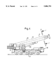
- FIG. 4 is a side view of a crane having a telescopic jib with the cross-section shown in FIG. 2.
- the cross-section shown in FIG. 1 represents a telescopic part identified in total by the reference numeral 1.
- the telescopic part 1 consists of an upper semi-box shaped section part 2 and a lower section part 3 connected thereto by the legs thereof extending straight down.
- Particularly of interest in FIG. 1 is the configuration according to the invention of the lower section part 3.
- the lower section part 3 is made up of four curved shell segments 4, 5, 6 and 7 arranged symmetrically with respect to a vertical plane through the longitudinal axis as shown.
- Each of the section parts 4 and 7 or 5 and 6 have, mirror inversely, the same shape.
- the section parts 4-7 are curved in the shape of a circular arc, the section parts 4 and 7 each having the indicated smaller radius R1 and the section parts 5 and 6 each having the indicated greater radius R2.
- the imaginary tangents intersect the circular arcs incident to each other at an obtuse angle in each case; kink edges being formed at the segment limits.
- the aforementioned kink edges endow the lower section part 3, which in operation of the crane is subjected to compression and torsional loading, with stability properties as achieved only by trussed section structures as regards stiffness.
- the curved segments 4, 5, 6 and 7 each include the advantages of arced section portions of such jibs relative to, as already mentioned, favorable properties in the application of forces, resistance to buckling and a shift in the cross-sectional contours outwardly away from the axis of the center of gravity of the section which likewise has a favorable effect on the stability.
- the two section parts are connected to each other; this being done in particular by welding.
- a telescopic jib configured in accordance with the embodiment as evident from FIG. 1 may be fabricated in a lesser material thickness due to its favorable stiffness and stability properties and its low tendency, as compared to configurations of prior art, to buckle in the compressive loading range.
- FIG. 4 illustrates a crane 20 having a retracted telescopic jib 22 according to the present invention.
- the telescopic jib 22 has one end mounted to a turntable 24, and the turntable is mounted to the superstructure 21 of the crane 20.
- a lift cylinder 26 raises and lowers the telescopic jib 22.
- the telescopic jib 22 includes a base part or section 8 and five telescopic parts or sections 1 telescoped one into the other.
- a shifting mechanism 28 extends and retracts the five telescopic parts 1.
- the shifting mechanism 28 may be well-known hydraulic piston/cylinder units and/or translated cable units.
- FIG. 2 shows a cross-section along line II--II of the telescopic jib 22 shown in FIG. 4.
- both the base part 8 and the five telescopic parts 1 correspond to those of the embodiment shown in FIG. 1.
- FIG. 2 What is particularly evident from FIG. 2 is that the close arrangement of the telescopic parts 1 telescoped one into the other permits a more compact construction for jibs of this kind.
- stiffening means such as welded stiffeners to counteract buckling
- FIG. 2 illustrates the base part 8 and all five telescopic parts 1 as having a cross-section according to the present invention as exemplified in FIG. 1, the present invention is not limited to this arrangement.
- the base part 8 could have the cross-section according to the present invention, or only one of the five telescopic parts 1 could have the cross-section according to the present invention.
- at least one of the base part 8 and the telescopic parts 1 has the cross-section according to the present invention.
- FIG. 3 shows in conclusion a combined view of section shapes together with a cross-section representation of a telescopic part 9 in accordance with the invention having the curved shell segments 10, 11 and 12 which form the lower section part.
- dashes 14 is the extreme case of a purely arc-shaped lower section part as a semi-ellipse.
- this elliptical shape has the best properties as regards the application of forces, it has the inherent deficiencies of trussed shapes as regards stiffness.
- the rectangular trussed structure is represented also in FIG. 3 by the dot-dashed lines 13.
- such configurations feature a good stiffness, they have disadvantages as regards the application of forces.
- the reference numeral 15 in FIG. 3 identifies a section shape which comprises bevels at the lower outer edges.
- the jib section according to the invention identified by the reference numeral 9 in FIG. 3 combines the positive force application properties of the arc shape with the stiffness of trussed structures.
- the embodiment represented in this case comprises three curved shell segments 10, 11, 12 in the shape of a circular arc, all three circular arcs having the indicated radius R1.
- a substantially planar contour materializes at the lowest point of the section in this configuration.
- the aforementioned advantages exist as regards force application, stiffness, resistance to buckling, and stability which characterize jibs according to the invention as compared to those of prior art.
Landscapes
- Engineering & Computer Science (AREA)
- Mechanical Engineering (AREA)
- Jib Cranes (AREA)
- Forklifts And Lifting Vehicles (AREA)
Abstract
Description
Claims (11)
Applications Claiming Priority (2)
| Application Number | Priority Date | Filing Date | Title |
|---|---|---|---|
| DE19624312A DE19624312C2 (en) | 1996-06-18 | 1996-06-18 | Telescopic boom for mobile cranes |
| DE19624312.2 | 1996-06-18 |
Publications (1)
| Publication Number | Publication Date |
|---|---|
| US5884791A true US5884791A (en) | 1999-03-23 |
Family
ID=7797278
Family Applications (1)
| Application Number | Title | Priority Date | Filing Date |
|---|---|---|---|
| US08/878,100 Expired - Lifetime US5884791A (en) | 1996-06-18 | 1997-06-18 | Telescopic jib for vehicular cranes |
Country Status (8)
| Country | Link |
|---|---|
| US (1) | US5884791A (en) |
| EP (1) | EP0814050B1 (en) |
| JP (1) | JPH10157980A (en) |
| KR (1) | KR980001805A (en) |
| CN (1) | CN1073047C (en) |
| CA (1) | CA2207407C (en) |
| DE (2) | DE19624312C2 (en) |
| ES (1) | ES2245787T3 (en) |
Cited By (16)
| Publication number | Priority date | Publication date | Assignee | Title |
|---|---|---|---|---|
| US6098824A (en) * | 1997-03-12 | 2000-08-08 | Mannesmann Ag | Telescopic crane boom section and a process for making sure |
| US6481587B2 (en) * | 2000-03-28 | 2002-11-19 | David J. Higgins | Pendant-supported telescoping boom crane |
| US6499612B1 (en) | 2001-07-27 | 2002-12-31 | Link-Belt Construction Equipment Co., L.P., Lllp | Telescoping boom assembly with rounded profile sections and interchangeable wear pads |
| US6508019B1 (en) * | 1997-07-15 | 2003-01-21 | Komatsu Ltd. | Boom of bucket type excavator and method for making same |
| US20030106871A1 (en) * | 2001-12-12 | 2003-06-12 | Franz Paschke | Telescopic jib for a vehicular crane |
| US20030126772A1 (en) * | 2002-01-04 | 2003-07-10 | Komatsu Ltd | Long structural member |
| US6726437B2 (en) | 2002-02-08 | 2004-04-27 | Clark Equipment Company | Telescoping loader lift arm |
| US20040168997A1 (en) * | 2001-06-11 | 2004-09-02 | Michael Irsch | Mobile crane comprising a telescopic principal jib |
| US20100155356A1 (en) * | 2007-09-05 | 2010-06-24 | Eckhard Wimmer | Profile shape for a crane boom |
| US20120199543A1 (en) * | 2011-02-09 | 2012-08-09 | Oshkosh Corporation | Boom for a crane assembly |
| US20130020274A1 (en) * | 2011-07-21 | 2013-01-24 | Arumugam Munuswamy | Tailor welded panel beam for construction machine and method of manufacturing |
| CN105584943A (en) * | 2016-01-15 | 2016-05-18 | 三一帕尔菲格特种车辆装备有限公司 | Crane boom and crane |
| US9718654B2 (en) | 2012-09-27 | 2017-08-01 | Tadano Ltd. | Telescopic boom |
| US20190062129A1 (en) * | 2017-08-31 | 2019-02-28 | Matthew Wendell Schroeder | Lightweight crane |
| US10414637B2 (en) * | 2016-06-03 | 2019-09-17 | Liebherr-Werk Ehingen Gmbh | Telescopic section having a variably extending fitting edge |
| CN110733979A (en) * | 2019-11-19 | 2020-01-31 | 姚运文 | Upper side light load single welding seam crane boom |
Families Citing this family (13)
| Publication number | Priority date | Publication date | Assignee | Title |
|---|---|---|---|---|
| FR2790538B1 (en) * | 1999-03-02 | 2001-05-25 | Ppm | HOLLOW BOX BEAM STRUCTURE, BEAM APPLIED AND TELESCOPIC ARROW IMPLEMENTING IT |
| EP1302435B1 (en) * | 2001-10-16 | 2018-03-07 | EFFER S.p.A. | A high strength telescopic arm |
| JP2006021877A (en) * | 2004-07-08 | 2006-01-26 | Tadano Ltd | Telescopic boom |
| EP1741663B1 (en) | 2005-07-07 | 2010-12-01 | Grove U.S. LLC | Upper boom cross section for telescopic cranes |
| DE102006014573B3 (en) | 2006-03-29 | 2007-07-19 | Manitowoc Crane Group France SAS, | Telescopic crane jib part, has upper and lower profile parts with segments that are bent outwardly, and end segments adjoining each other at obtuse angle, where radius of segments is less than half width of cross-section |
| JP2010089919A (en) * | 2008-01-09 | 2010-04-22 | Kobelco Cranes Co Ltd | Telescopic boom |
| JP5581072B2 (en) * | 2010-02-04 | 2014-08-27 | 株式会社タダノ | Boom and crane |
| US8070084B2 (en) * | 2010-02-05 | 2011-12-06 | Metso Minerals Industries, Inc. | Spider having spider arms with open channel |
| DE202010006624U1 (en) | 2010-05-10 | 2010-08-05 | Manitowoc Crane Group France Sas | Crane jib, in particular mobile crane jib, with prestressed tension elements |
| WO2014077791A1 (en) * | 2012-11-13 | 2014-05-22 | Hi̇drokon Konya Hi̇droli̇k Maki̇na Sanayi̇ Ve Ti̇caret Li̇mi̇ted Şi̇rketi̇ | Telescopic boom of high efficiency for cranes |
| FI126628B (en) | 2013-04-11 | 2017-03-15 | Bronto Skylift Oy Ab | Boom and elevator |
| CN103241663A (en) * | 2013-05-07 | 2013-08-14 | 三一帕尔菲格特种车辆装备有限公司 | Crane, and telescopic arm and knuckle arm thereof |
| CN109573866A (en) * | 2017-09-29 | 2019-04-05 | 中国铁路总公司 | A kind of locomotive crane |
Citations (11)
| Publication number | Priority date | Publication date | Assignee | Title |
|---|---|---|---|---|
| US3719403A (en) * | 1970-11-17 | 1973-03-06 | Kidde & Co Walter | Crane boom having wear pads |
| DE2317595A1 (en) * | 1973-04-07 | 1974-10-31 | Kaspar Klaus | TELESCOPIC UNIT, IN PARTICULAR FOR LIFTING EQUIPMENT |
| US3931698A (en) * | 1974-11-20 | 1976-01-13 | The Warner & Swasey Company | Center guided crane boom |
| US4168008A (en) * | 1978-02-23 | 1979-09-18 | Granryd Tod G | Telescopic crane boom having corrugated boom sections |
| DE3015599A1 (en) * | 1980-04-23 | 1981-10-29 | Peter Dipl.-Ing. Dr. 4000 Düsseldorf Eiler | Telescopic jib for mobile crane - has hollow triangular aluminium sections reinforced by steel inserts in contact with rollers |
| DE3042993A1 (en) * | 1980-11-14 | 1982-07-01 | Fried. Krupp Gmbh, 4300 Essen | Telescopic crane jib with plastics bearings - is of angular cross=section at bottom and radiused at top |
| US4459786A (en) * | 1981-10-27 | 1984-07-17 | Ro Corporation | Longitudinally bowed transversely polygonal boom for cranes and the like |
| DE9210902U1 (en) * | 1992-08-14 | 1992-12-24 | Liebherr-Werk Ehingen Gmbh, 7930 Ehingen | Telescopic boom for mobile cranes or similar |
| FR2681649A1 (en) * | 1991-09-24 | 1993-03-26 | Krupp Industrietech | HYDROMECHANICAL TELESCOPING SYSTEM, ESPECIALLY FOR A MOTOR CRANE. |
| DE9308993U1 (en) * | 1993-06-16 | 1993-08-12 | Ec Engineering + Consulting Spezialmaschinen Gmbh, 89079 Ulm | Telescopic boom |
| EP0668238A1 (en) * | 1994-02-18 | 1995-08-23 | EC Engineering + Consulting Spezialmaschinen GmbH | Boom profile |
Family Cites Families (4)
| Publication number | Priority date | Publication date | Assignee | Title |
|---|---|---|---|---|
| DE2148966C3 (en) * | 1971-09-30 | 1978-11-23 | Liebherr-Werk Ehingen Gmbh, 7930 Ehingen | Telescopic boom, especially for road-traveling cranes |
| JPS5049868U (en) * | 1973-09-07 | 1975-05-15 | ||
| ATE123743T1 (en) * | 1991-02-11 | 1995-06-15 | Liebherr Werk Ehingen | TELESCOPIC BOOM FOR VEHICLE CRANES OR THE LIKE. |
| DE4344795A1 (en) * | 1993-12-28 | 1995-06-29 | Liebherr Werk Ehingen | Mobile crane with a telescopic boom |
-
1996
- 1996-06-18 DE DE19624312A patent/DE19624312C2/en not_active Expired - Fee Related
-
1997
- 1997-06-10 CA CA002207407A patent/CA2207407C/en not_active Expired - Fee Related
- 1997-06-17 EP EP97109839A patent/EP0814050B1/en not_active Expired - Lifetime
- 1997-06-17 ES ES97109839T patent/ES2245787T3/en not_active Expired - Lifetime
- 1997-06-17 DE DE69733860T patent/DE69733860T2/en not_active Expired - Lifetime
- 1997-06-18 KR KR1019970025324A patent/KR980001805A/en active Search and Examination
- 1997-06-18 JP JP9161712A patent/JPH10157980A/en active Pending
- 1997-06-18 US US08/878,100 patent/US5884791A/en not_active Expired - Lifetime
- 1997-06-18 CN CN97113634A patent/CN1073047C/en not_active Expired - Fee Related
Patent Citations (11)
| Publication number | Priority date | Publication date | Assignee | Title |
|---|---|---|---|---|
| US3719403A (en) * | 1970-11-17 | 1973-03-06 | Kidde & Co Walter | Crane boom having wear pads |
| DE2317595A1 (en) * | 1973-04-07 | 1974-10-31 | Kaspar Klaus | TELESCOPIC UNIT, IN PARTICULAR FOR LIFTING EQUIPMENT |
| US3931698A (en) * | 1974-11-20 | 1976-01-13 | The Warner & Swasey Company | Center guided crane boom |
| US4168008A (en) * | 1978-02-23 | 1979-09-18 | Granryd Tod G | Telescopic crane boom having corrugated boom sections |
| DE3015599A1 (en) * | 1980-04-23 | 1981-10-29 | Peter Dipl.-Ing. Dr. 4000 Düsseldorf Eiler | Telescopic jib for mobile crane - has hollow triangular aluminium sections reinforced by steel inserts in contact with rollers |
| DE3042993A1 (en) * | 1980-11-14 | 1982-07-01 | Fried. Krupp Gmbh, 4300 Essen | Telescopic crane jib with plastics bearings - is of angular cross=section at bottom and radiused at top |
| US4459786A (en) * | 1981-10-27 | 1984-07-17 | Ro Corporation | Longitudinally bowed transversely polygonal boom for cranes and the like |
| FR2681649A1 (en) * | 1991-09-24 | 1993-03-26 | Krupp Industrietech | HYDROMECHANICAL TELESCOPING SYSTEM, ESPECIALLY FOR A MOTOR CRANE. |
| DE9210902U1 (en) * | 1992-08-14 | 1992-12-24 | Liebherr-Werk Ehingen Gmbh, 7930 Ehingen | Telescopic boom for mobile cranes or similar |
| DE9308993U1 (en) * | 1993-06-16 | 1993-08-12 | Ec Engineering + Consulting Spezialmaschinen Gmbh, 89079 Ulm | Telescopic boom |
| EP0668238A1 (en) * | 1994-02-18 | 1995-08-23 | EC Engineering + Consulting Spezialmaschinen GmbH | Boom profile |
Cited By (23)
| Publication number | Priority date | Publication date | Assignee | Title |
|---|---|---|---|---|
| US6098824A (en) * | 1997-03-12 | 2000-08-08 | Mannesmann Ag | Telescopic crane boom section and a process for making sure |
| US6508019B1 (en) * | 1997-07-15 | 2003-01-21 | Komatsu Ltd. | Boom of bucket type excavator and method for making same |
| US6637111B2 (en) | 1997-07-15 | 2003-10-28 | Komatsu Ltd. | Method for making a boom of an excavator |
| US6481587B2 (en) * | 2000-03-28 | 2002-11-19 | David J. Higgins | Pendant-supported telescoping boom crane |
| US7172082B2 (en) * | 2001-06-11 | 2007-02-06 | Terex-Demag Gmbh & Co. Kg | Mobile crane with a telescopic main boom |
| US20040168997A1 (en) * | 2001-06-11 | 2004-09-02 | Michael Irsch | Mobile crane comprising a telescopic principal jib |
| US6499612B1 (en) | 2001-07-27 | 2002-12-31 | Link-Belt Construction Equipment Co., L.P., Lllp | Telescoping boom assembly with rounded profile sections and interchangeable wear pads |
| US6978907B2 (en) * | 2001-12-12 | 2005-12-27 | Grove U.S. Llc | Telescopic jib for a vehicular crane |
| US20030106871A1 (en) * | 2001-12-12 | 2003-06-12 | Franz Paschke | Telescopic jib for a vehicular crane |
| US20030126772A1 (en) * | 2002-01-04 | 2003-07-10 | Komatsu Ltd | Long structural member |
| US6726437B2 (en) | 2002-02-08 | 2004-04-27 | Clark Equipment Company | Telescoping loader lift arm |
| US20100155356A1 (en) * | 2007-09-05 | 2010-06-24 | Eckhard Wimmer | Profile shape for a crane boom |
| US7878349B2 (en) * | 2007-09-05 | 2011-02-01 | Palfinger Ag | Profile shape for a crane boom |
| US20120199543A1 (en) * | 2011-02-09 | 2012-08-09 | Oshkosh Corporation | Boom for a crane assembly |
| US9290363B2 (en) * | 2011-07-21 | 2016-03-22 | Manitowoc Crane Companies, Llc | Tailor welded panel beam for construction machine and method of manufacturing |
| EP2865632A1 (en) * | 2011-07-21 | 2015-04-29 | Manitowoc Crane Companies, LLC | Tailor welded panel beam for construction machine and method of manufacturing |
| US20130020274A1 (en) * | 2011-07-21 | 2013-01-24 | Arumugam Munuswamy | Tailor welded panel beam for construction machine and method of manufacturing |
| US9718654B2 (en) | 2012-09-27 | 2017-08-01 | Tadano Ltd. | Telescopic boom |
| CN105584943A (en) * | 2016-01-15 | 2016-05-18 | 三一帕尔菲格特种车辆装备有限公司 | Crane boom and crane |
| US10414637B2 (en) * | 2016-06-03 | 2019-09-17 | Liebherr-Werk Ehingen Gmbh | Telescopic section having a variably extending fitting edge |
| US20190062129A1 (en) * | 2017-08-31 | 2019-02-28 | Matthew Wendell Schroeder | Lightweight crane |
| US10894699B2 (en) * | 2017-08-31 | 2021-01-19 | Stellar Industries, Inc. | Lightweight crane |
| CN110733979A (en) * | 2019-11-19 | 2020-01-31 | 姚运文 | Upper side light load single welding seam crane boom |
Also Published As
| Publication number | Publication date |
|---|---|
| DE69733860T2 (en) | 2006-03-23 |
| JPH10157980A (en) | 1998-06-16 |
| DE69733860D1 (en) | 2005-09-08 |
| EP0814050A1 (en) | 1997-12-29 |
| ES2245787T3 (en) | 2006-01-16 |
| KR980001805A (en) | 1998-03-30 |
| CA2207407C (en) | 2006-10-31 |
| DE19624312A1 (en) | 1998-01-08 |
| CN1171365A (en) | 1998-01-28 |
| CN1073047C (en) | 2001-10-17 |
| CA2207407A1 (en) | 1997-12-18 |
| EP0814050B1 (en) | 2005-08-03 |
| DE19624312C2 (en) | 2000-05-31 |
Similar Documents
| Publication | Publication Date | Title |
|---|---|---|
| US5884791A (en) | Telescopic jib for vehicular cranes | |
| US9637358B2 (en) | Mobile telescopic crane | |
| US4337601A (en) | High-strength light-weight boom section for telescopic crane boom | |
| JP6550301B2 (en) | Reinforcement structure of lattice boom | |
| US6516962B1 (en) | Telescopic boom for cranes | |
| US6978907B2 (en) | Telescopic jib for a vehicular crane | |
| US7578402B2 (en) | Telescopic crane jib part with cross sectional segments of varying curvature | |
| US20210188601A1 (en) | Mobile crane | |
| CA2549448C (en) | Upper chord cross-section for telescopic parts of a crane | |
| US7878349B2 (en) | Profile shape for a crane boom | |
| US6086256A (en) | Telescopic jib bearing assembly with embossments | |
| EP2078693A1 (en) | Telescopic boom | |
| CN201301181Y (en) | Retractable jib | |
| US20190127998A1 (en) | Hollow two-point lever | |
| CN114249260A (en) | A section arm cylinder and a jib | |
| JP2020152488A (en) | Structure of boom | |
| CA2697299A1 (en) | Profile shape for a crane jib | |
| CA2697301C (en) | Profile shape for a crane boom | |
| DE102012210112B3 (en) | Mobile telescopic crane comprises telescopic arm with three sub-arms, where lower sub-arm faces undercarriage and two upper sub-arms are turned away from undercarriage and are hinged to undercarriage, and sub-arm is made of sub-arm sections | |
| CA2697304A1 (en) | Profile shape for a crane boom | |
| JPH038696A (en) | Outrigger of special vehicle | |
| JP3155989B2 (en) | Cross section structure of multi-stage boom | |
| JPH055796U (en) | Multi-stage telescopic boom |
Legal Events
| Date | Code | Title | Description |
|---|---|---|---|
| AS | Assignment |
Owner name: KIDDE INDUSTRIES, INC., PENNSYLVANIA Free format text: ASSIGNMENT OF ASSIGNORS INTEREST;ASSIGNORS:VOHDIN, KURT;PASCHKE, FRANZ;NEUMANN, HANS;AND OTHERS;REEL/FRAME:008633/0907 Effective date: 19970611 |
|
| AS | Assignment |
Owner name: CHASE BANK OF TEXAS, NATIONAL ASSOCIATION, AS ADMI Free format text: SECURITY INTEREST;ASSIGNORS:GROVE HOLDINGS LLC (DE LIMITED LIABLITY CORPORATION);GROVE WORLDWIDE LLC (DE LIMITED LIABILITY CORP.);GROVE CAPITAL, INC. (DE CORPORATION);AND OTHERS;REEL/FRAME:009342/0001 Effective date: 19980429 |
|
| AS | Assignment |
Owner name: GROVE U.S. L.L.C., PENNSYLVANIA Free format text: ASSIGNMENT OF ASSIGNORS INTEREST;ASSIGNOR:KIDDE INDUSTRIES, INC.;REEL/FRAME:009463/0144 Effective date: 19980429 |
|
| STCF | Information on status: patent grant |
Free format text: PATENTED CASE |
|
| FPAY | Fee payment |
Year of fee payment: 4 |
|
| AS | Assignment |
Owner name: JPMORGAN CHASE BANK, N.A., AS AGENT, ILLINOIS Free format text: SECURITY INTEREST;ASSIGNOR:GROVE U.S. L.L.C.;REEL/FRAME:016446/0082 Effective date: 20050610 |
|
| FPAY | Fee payment |
Year of fee payment: 8 |
|
| AS | Assignment |
Owner name: JPMORGAN CHASE BANK, N.A., AS AGENT, ILLINOIS Free format text: SECURITY AGREEMENT;ASSIGNOR:GROVE U.S. L.L.C.;REEL/FRAME:022399/0511 Effective date: 20080414 Owner name: JPMORGAN CHASE BANK, N.A., AS AGENT,ILLINOIS Free format text: SECURITY AGREEMENT;ASSIGNOR:GROVE U.S. L.L.C.;REEL/FRAME:022399/0511 Effective date: 20080414 |
|
| AS | Assignment |
Owner name: GROVE U.S., L.L.C., PENNSYLVANIA Free format text: RELEASE OF SECURITY INTERESTIN U.S. PATENTS;ASSIGNOR:JPMORGAN CHASE BANK, N.A., AS AGENT;REEL/FRAME:022416/0063 Effective date: 20081106 Owner name: GROVE U.S., L.L.C.,PENNSYLVANIA Free format text: RELEASE OF SECURITY INTEREST IN U.S. PATENTS;ASSIGNOR:JPMORGAN CHASE BANK, N.A., AS AGENT;REEL/FRAME:022416/0063 Effective date: 20081106 Owner name: GROVE U.S., L.L.C., PENNSYLVANIA Free format text: RELEASE OF SECURITY INTEREST IN U.S. PATENTS;ASSIGNOR:JPMORGAN CHASE BANK, N.A., AS AGENT;REEL/FRAME:022416/0063 Effective date: 20081106 |
|
| FEPP | Fee payment procedure |
Free format text: PAYOR NUMBER ASSIGNED (ORIGINAL EVENT CODE: ASPN); ENTITY STATUS OF PATENT OWNER: LARGE ENTITY |
|
| FPAY | Fee payment |
Year of fee payment: 12 |
|
| AS | Assignment |
Owner name: MANITOWOC CRANE GROUP FRANCE SAS, FRANCE Free format text: ASSIGNMENT OF ASSIGNORS INTEREST;ASSIGNOR:GROVE U.S. L.L.C.;REEL/FRAME:027002/0070 Effective date: 20110429 |
|
| AS | Assignment |
Owner name: CRANE HOLDING INC., PENNSYLVANIA Free format text: RELEASE BY SECURED PARTY;ASSIGNOR:JPMORGAN CHASE BANK, N.A., AS COLLATERAL AGENT;REEL/FRAME:037900/0118 Effective date: 20160303 Owner name: GROVE FINANCE LLC, PENNSYLVANIA Free format text: RELEASE BY SECURED PARTY;ASSIGNOR:JPMORGAN CHASE BANK, N.A., AS COLLATERAL AGENT;REEL/FRAME:037900/0118 Effective date: 20160303 Owner name: GROVE WORLDWIDE LLC, PENNSYLVANIA Free format text: RELEASE BY SECURED PARTY;ASSIGNOR:JPMORGAN CHASE BANK, N.A., AS COLLATERAL AGENT;REEL/FRAME:037900/0118 Effective date: 20160303 Owner name: GROVE HOLDINGS LLC, PENNSYLVANIA Free format text: RELEASE BY SECURED PARTY;ASSIGNOR:JPMORGAN CHASE BANK, N.A., AS COLLATERAL AGENT;REEL/FRAME:037900/0118 Effective date: 20160303 Owner name: GROVE CAPITAL LLC, PENNSYLVANIA Free format text: RELEASE BY SECURED PARTY;ASSIGNOR:JPMORGAN CHASE BANK, N.A., AS COLLATERAL AGENT;REEL/FRAME:037900/0118 Effective date: 20160303 Owner name: CRANE ACQUISITION CORPORATION, PENNSYLVANIA Free format text: RELEASE BY SECURED PARTY;ASSIGNOR:JPMORGAN CHASE BANK, N.A., AS COLLATERAL AGENT;REEL/FRAME:037900/0118 Effective date: 20160303 Owner name: GROVE U.S. LLC, PENNSYLVANIA Free format text: RELEASE BY SECURED PARTY;ASSIGNOR:JPMORGAN CHASE BANK, N.A., AS COLLATERAL AGENT;REEL/FRAME:037900/0118 Effective date: 20160303 Owner name: GROVE U.S., L.L.C., PENNSYLVANIA Free format text: RELEASE BY SECURED PARTY;ASSIGNOR:JPMORGAN CHASE BANK, N.A., AS COLLATERAL AGENT;REEL/FRAME:037899/0268 Effective date: 20160303 Owner name: GROVE U.S., L.L.C., PENNSYLVANIA Free format text: RELEASE BY SECURED PARTY;ASSIGNOR:JPMORGAN CHASE BANK, N.A., AS COLLATERAL AGENT;REEL/FRAME:038007/0285 Effective date: 20160303 |