US5740394A - Apparatus for transferring data divided into blocks with address boundaries - Google Patents
Apparatus for transferring data divided into blocks with address boundaries Download PDFInfo
- Publication number
- US5740394A US5740394A US08/844,993 US84499397A US5740394A US 5740394 A US5740394 A US 5740394A US 84499397 A US84499397 A US 84499397A US 5740394 A US5740394 A US 5740394A
- Authority
- US
- United States
- Prior art keywords
- data
- memory
- buffers
- transfer
- destination
- Prior art date
- Legal status (The legal status is an assumption and is not a legal conclusion. Google has not performed a legal analysis and makes no representation as to the accuracy of the status listed.)
- Expired - Fee Related
Links
Images


Classifications
-
- G—PHYSICS
- G06—COMPUTING; CALCULATING OR COUNTING
- G06F—ELECTRIC DIGITAL DATA PROCESSING
- G06F13/00—Interconnection of, or transfer of information or other signals between, memories, input/output devices or central processing units
- G06F13/38—Information transfer, e.g. on bus
- G06F13/42—Bus transfer protocol, e.g. handshake; Synchronisation
- G06F13/4204—Bus transfer protocol, e.g. handshake; Synchronisation on a parallel bus
- G06F13/4234—Bus transfer protocol, e.g. handshake; Synchronisation on a parallel bus being a memory bus
- G06F13/4243—Bus transfer protocol, e.g. handshake; Synchronisation on a parallel bus being a memory bus with synchronous protocol
Definitions
- This invention relates to a data transfer apparatus for sending and receiving data between two memories.
- FIG. 39 of the accompanying drawings shows a conventional data transfer apparatus disclosed in, for example, Japanese Patent Laid-Open Publication No. HEI 3-131951.
- reference numeral 1 designates a source memory in which data to be transferred is stored; 2, a destination memory for storing data newly transferred; 3, a data transfer apparatus situated between the two memories 1, 2 for transferring data between the memories 1, 2; 4a, 4b, buffers for temporarily storing data being transferred; 5, a source side control means situated between the buffers 4a, 4b and the source memory 1 for switching over the buffers and for controlling the transfer of data; 6, a destination side control means situated between buffers 4a, 4b and the destination memory 2 for switching over the buffers and for controlling the transfer of data; 7a-7d, data blocks into which the source memory 1 is divided by address boundaries; and 8a-8e, data blocks into which the destination memory 2 is divided by address boundaries.
- the size of each of the buffers 4a, 4b and the data blocks 7a-7d, 8b-8d is four bytes.
- FIGS. 40 through 47 show transitional statuses corresponding to the respective procedural steps.
- step 1 as shown in FIG. 40, all data (right-slant hatched portion) of the data block 7a of the source memory 1 is transferred in terms of blocks to the right-slant hatched portion of the buffer 4a via the source side control means 5.
- step 2 as shown in FIG. 41, the data in the right-slant hatched portion of the buffer 4a is transferred to the right-slant hatched portion of the data block 8a of the destination memory 2 via the destination side control means 6 and, at the same time, all data (left-slant hatched portion) of the delta block 7b is transferred to the left-slant hatched portion of the buffer 4b via the source side control means 5.
- step 3 as shown in FIG. 42, the data in the remaining portion (right-slant hatched portion) of the buffer 4a and the data in the left-slant hatched portion of the buffer 4b are transferred to the corresponding hatched portions of the data block 8b via the destination side control means 6.
- the data of the data block 7c of the source memory 1 cannot be transferred to the buffer 4a.
- step 4 as shown in FIG. 43, all data (right-slant hatched portion) of the data block 7c is transferred in terms of blocks to the right-slant hatched portion of the buffer 4a via the source side control means 5. At that time, since the data in the buffer 4a is still being transferred, the data of the buffers 4b, 4a cannot be simultaneously transferred to the data block 8c of the destination memory 2.
- step 5 as shown in FIG. 44, the data in the remaining portion (left-slant hatched portion) of the buffer 4b and the data in the right-slant hatched portion of the buffer 4a are transferred to the source side control means 6. At that time, since the buffer 4b is still in use, the data of the data block 7d of the source memory 1 cannot be transferred to the buffer 4b.
- step 6 as shown in FIG. 45, all data (left-slant hatched portion) of the data block 7d is transferred to the left-slant hatched portion of the buffer 4b via the source side control means 5. At that time, since the data in the buffer 4b are still being transferred, the data of the buffers 4a, 4b cannot be simultaneously transferred to the data block 8d of the destination memory 2.
- step 7 as shown in FIG. 46, the data in the remaining portion (right-slant hatched portion) of the buffer 4a and the data in the left-slant hatched portion of the buffer 4b are transferred to the corresponding hatched portion of the data block 8d via the destination side control means 6.
- step 8 as shown in FIG. 47, the data in the remaining portion (left-slant hatched portion) of the buffer 4b is transferred to the data block 8e via the destination side control means 6.
- FIG. 48 shows time series operations of the source memory 1, the destination memory 2 and the buffers 4a, 4b in procedural steps 1-8.
- steps 3-6 of the foregoing procedure are repeated a number of times.
- the transfer start address does not satisfy the address boundary condition
- the data transfer from the source memory 1 to the data transfer apparatus 3 and the data transfer from the data transfer apparatus to the destination memory 2 cannot be performed simultaneously in the absence of the procedural step 2 as shown in FIG. 41.
- the transfer start address does not satisfy the address boundary condition
- the data transfer speed would be slower, compared to the case where the transfer start address satisfies the address boundary condition.
- a data transfer apparatus for transferring data between two memories each having a number of data blocks separated by address boundaries, comprising: three or more buffers for temporarily storing the data being transferred; source side control means situated between the buffers and the source memory for switching the buffers and for transferring the data in terms of blocks in such a manner that the leading buffer coincides with the address boundary of the source memory; and destination side control means situated between the buffers and the destination memory for switching the buffers and for controlling the transfer of the data in terms of blocks.
- the destination side control means is operable to transfer the data in blocks from the transfer start address of the source memory to the next address boundary when the transfer start address of the source memory does not coincide with the address boundary.
- a data transfer apparatus for transferring data between two memories each having a number of data blocks separated by address boundaries, comprising: three or more buffers for temporarily storing the data being transferred; source side control means situated between the buffers and the source memory for switching the buffers and for controlling the transfer of the data in terms of blocks; and destination side control means situated between the buffers and the destination memory for switching the buffers and for transferring the data in terms of blocks in such a manner that the leading buffer coincides with the address boundary of the destination memory.
- the destination side control means is operable to transfer the data in blocks from the transfer head address of the destination memory to the next address boundary when the transfer head address of the destination memory does not coincide with the address boundary.
- the data transfer apparatus of this invention by switching over three or more buffers successively during data transfer between the source memory and the destination memory, it is possible to perform the data transfer between the source memory to the data transfer apparatus and the data transfer between the data transfer apparatus to the destination memory simultaneously even if the transfer start address of the source memory does not satisfy the address boundary condition and/or if the transfer head address of the destination memory does not satisfy the address boundary condition.
- FIG. 1 is a diagram showing a data transfer apparatus according to a first embodiment of this invention
- FIGS. 2 through 8 show transitional statuses of the data transfer apparatus of FIG. 1 as buffers are switched over successively;
- FIG. 9 shows time series operations of a source memory, a destination memory and the individual buffers in the data transfer apparatus of the first embodiment
- FIG. 10 is a diagram showing another data transfer apparatus according to a second embodiment
- FIGS. 11 through 17 show transitional statuses of the data transfer apparatus of FIG. 10 as buffers are switched over successively;
- FIG. 18 shows time series operations of a source memory, a destination memory and the individual buffers in the data transfer apparatus of the second embodiment
- FIG. 19 is a diagram showing still another data transfer apparatus according to a third embodiment.
- FIGS. 20 through 27 show transitional statuses of the data transfer apparatus of FIG. 19 as buffers are switched over successively;
- FIG. 28 shows time series operations of a source memory, a destination memory and the individual buffers in the data transfer apparatus of the third embodiment
- FIG. 29 is a diagram showing a further data transfer apparatus according to a fourth embodiment.
- FIGS. 30 through 37 show transitional statuses of the data transfer apparatus of FIG. 29 as buffers are switched over successively;
- FIG. 38 shows time series operations of a source memory, a destination memory and the individual buffers in the data transfer apparatus of the fourth embodiment
- FIG. 39 is a diagram showing a conventional transfer apparatus
- FIGS. 40 through 47 show transitional statuses of the conventional data transfer apparatus as buffers are switched over.
- FIG. 48 shows time series operations of a source memory, a destination memory and the individual buffers in the conventional data transfer apparatus.
- FIG. 1 is a diagram showing a first embodiment of this invention as defined in claim 1.
- reference numeral 1 designates a source memory in which data to be transferred is stored; 2, a destination memory for storing data newly transferred; and 31, a data transfer apparatus situated between the two memories 1, 2 for transferring data between the memories 1, 2.
- the data transfer apparatus 31 comprises three buffers 4a, 4b, 4c for temporarily storing data being transferred, a source side control means 51 situated between the buffers 4a, 4b, 4c and the source memory 1 for switching over the buffers and for controlling the transfer of data, and a destination side control means 61 situated between buffers 4a, 4b, 4c and the destination memory 2 for switching over the buffers and for controlling the transfer of data.
- each of the data blocks 7a-7e, 8b-8e designate data blocks into which the source memory 1 is divided by address boundaries
- 8a-8e designate data blocks into which the destination memory 2 is divided by address boundaries. It is necessary that the size of each of the data blocks 7a-7e, 8b-8e should be equal to that of the individual buffers 4a, 4b, 4c. In this embodiment, likewise the conventional art, the size is four bytes. Alternatively, it may be eight bytes or 32 bytes. Practically, however, the total size of the data blocks 8a, 8f is equal to the size of a single data block, i.e., four bytes. For convenience, the data blocks 8a, 8f are treated as a single data block. Also in the following other embodiments, the data blocks 8a, 8f are treated likewise those of this embodiment.
- FIGS. 2 through 8 show transitional statuses corresponding to the individual procedural steps.
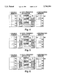
- step 1 as shown in FIG. 2, all data (right-slant hatched portion) of the data block 7a is transferred to the right-slant hatched portion of the buffer 4a via the source side control means 51.
- the data in the right-slant hatched portion of the buffer 4a is transferred to the right-slant hatched portion of the data block 8a of the destination memory 2 via the destination side control means 61 and, at the same time, all data (horizontal hatched portion) of the data block 7b is transferred to the horizontal hatched portion of the buffer 4b via the source side control means 51.
- all data (horizontal hatched portion) of the data block 7b is transferred to the horizontal hatched portion of the buffer 4b via the source side control means 51.
- 2-byte data is to be transferred to the data block 8a
- only 2-byte data out of 4-byte data in the buffer 4a is transferred.
- the 2-byte data in the remaining portion (right-slant hatched portion) of the buffer 4a and the 2-byte data (horizontal hatched portion), which has such a size as to satisfy the 4-byte data block 8b, of the buffer 4b are transferred in a single block of data to the corresponding hatched portions of the data block 8b via the destination side control means 61.
- all data (left-slant hatched portion) of the data block 7c is transferred to the left-slant hatched portion of the buffer 4c via the source side control means 51.
- the 2-byte data in the remaining portion (horizontal hatched portion) of the buffer 4b and the 2-byte data (left-slant hatched portion), which has such a size as to satisfy the 4-byte data block 8c, of the data 4c are transferred as a single block of data to the corresponding hatched portions of the data block 8c via the destination side control means 61.
- all data (right-slant hatched portion) of the data block 7d is transferred to the right-slant hatched portion via the source side control means 51. Since the data in the buffer 4a has already been transferred to the destination memory 2 in steps 2 and 3, the buffer 4a can be used.
- the 2-byte data in the remaining portion (left-slant hatched portion) of the buffer 4c and the 2-byte data (right-slant hatched portion), which has such a size as to satisfy the 4-byte data block 8d, of the buffer 4a are transferred as a single block of data to the corresponding hatched portions of the data block 8d via the destination side control means 61.
- all data (horizontal hatched portion) of the data block 7e is transferred to the horizontal hatched portion of the buffer 4b via the source side control means 51. Since the data in the buffer 4b has already been transferred to the destination memory 2 in steps 3 and 4, the buffer 4b can be used.
- the 2-byte data in the remaining portion (right-slant hatched portion) of the buffer 4a and the 2-byte data (horizontal hatched portion), which has such a size as to satisfy the 4-byte data block 8e, of the buffer 4b are transferred as a single block of data to the corresponding portions of the data block 8e via the destination side control means 61.
- the 2-byte data in the remaining portion (horizontal hatched portion) of the buffer 4b is transferred to the horizontal hatched portion of the data block 8f via the destination side control means 61.
- the data transfer in terms of blocks takes place in such a manner that the head of the buffers 4a, 4b, 4c coincides with the address boundary of the source memory 1. Meanwhile in the destination side control means 61, the data transfer is controlled in such a manner that the remaining data and part of data of the next buffer constitute a single block of data. Thus the data is transferred from the data blocks 7a-7e of the source memory 1 to the data blocks 8a-8f of the destination memory 2.
- FIG. 9 shows time series operations of the source memory 1, the destination memory 2 and the individual buffers 4a, 4b, 4c in procedural steps.
- the data transfer from the source memory 1 to the data transfer apparatus 31 and the data transfer from the data transfer apparatus 31 to the destination memory 2 can take place even if the transfer head address of the destination memory 2 does not satisfy the address boundary condition.
- the data of five data blocks 7a-7e is transferred from the source memory 1; in order to transfer data of more than five data blocks, the procedural steps 3-5 are repeated.
- seven procedural steps are necessary to transfer five blocks of data, and one more step is necessary to transfer one more block of data.
- N number of blocks of data can be transferred in (N+2) number of procedural steps, high-speed data transfer can be achieved.
- FIG. 10 is a diagram showing a second embodiment of this invention as defined in claim 2.
- Reference numeral 32 designates a data transfer apparatus situated between two memories 1, 2 for transferring data between the memories 1, 2.
- the data transfer apparatus 32 comprises three buffers 4a, 4b, 4c, a source side control means 52 situated between the buffers 4a, 4b, 4c and the source memory 1 for switching over the buffers 4a, 4b, 4c and for controlling the transfer of data in terms of blocks, and a destination side control means 62 situated between the buffers 4a, 4b, 4c and the destination memory 2 for switching over the buffers 4a, 4b, 4c and for controlling the transfer of data in terms of blocks in such a manner that the head of the buffers 4a, 4b, 4c coincides with the address boundary of the destination memory 2.
- 7a-7f designate data blocks into which the source memory 1 is divided by address boundaries
- 8a-8e designate data blocks into which the destination memory 2 is divided by address boundaries.
- FIGS. 11 through 17 show transitional steps and statuses corresponding to the individual procedural steps.
- portions indicated by hatching represent data in the corresponding data blocks and buffers likewise the first embodiment; therefore their description is omitted, if not necessary. This is the same in the following embodiments.
- step 1 data is transferred from the data block 7a of the source memory 1 to the buffer 4a via the source side control means 52. At that time, the data is stored in the buffer 4a from its head.
- step 2 data is transferred from the data block 7b of the source memory 1 to the buffers 4a, 4b via the source side control means 52.
- step 2 data is transferred from the data block 7b of the source memory 1 to the buffers 4a, 4b via the source side control means 52.
- step 2 data is transferred from the data block 7b of the source memory 1 to the buffers 4a, 4b via the source side control means 52.
- step 2 data is transferred from the data block 7b of the source memory 1 to the buffers 4a, 4b via the source side control means 52.
- an amount of data corresponding to the part of buffer 4a not used in step 1 is stored in the buffer 4a, and then the remaining data is stored in the buffer 4b from its head.
- step 3 data transfer from the buffer 4a to the data block 8a of the destination memory 2 via the destination side control means 62 and data transfer from the data block 7c of the source memory 1 to the buffers 4b, 4c via the source side control means 52 take place simultaneously.
- data to be transferred firstly an amount of data corresponding to that part of the buffer 4b not used in step 2 is stored in the buffer 4b, and then the remaining data is stored in the buffer 4c from its head.
- step 4 data transfer from the buffer 4b to the data block 8b of the destination memory 2 via the destination side control means 62 and data transfer from the data block 7d of the source memory 1 to the buffers 4c, 4a via the source side control means 52 take place simultaneously. Since the data in the buffer 4a has already been transferred to the destination memory 2 in step 3, the buffer 4a can be used. Of data to be transferred from the data block 7d, firstly an amount of data corresponding to that part of the buffer 4c not used in step 3 is stored in the buffer 4c, and then the remaining data is stored in the buffer 4a from its head.
- step 5 data transfer from the buffer 4c to the data block 8c of the destination memory 2 via the destination side control means 62 and data transfer from the data block 7e of the source memory 1 to the buffers 4a, 4b via the source side control means 52 take place simultaneously. Since the data in the buffer 4b has already been transferred to the destination memory 2 in step 4, the buffer 4b can be used. Of data to be transferred from the data block 7e, firstly an amount of data corresponding to that part of the buffer 4a not used in step 4 is stored in the buffer 4a, and then the remaining data is stored in the buffer 4b from its head.
- step 6 data is transferred from the buffer 4a to the data block 8d of the destination memory 2 via the destination side control means 62 and, at the same time, data is transferred from the data block 7f of the source memory to the buffer 4b behind the data stored in step 5.
- step 7 data is transferred from the buffer 4b to the data block 8e of the destination memory 2 via the destination side control means 62.
- the data of the data blocks 7a-7f of the source memory 1, which data have been transferred in terms of blocks, are stored successively in the individual buffers 4a, 4b, 4c in such a manner that the remaining data and part of the next data fill the individual buffers 4a, 4b, 4c.
- the destination side control means 62 data transfer in terms of blocks takes place in such a manner that the head of the buffers 4a, 4b, 4c coincides with the address boundary of the destination memory 2, thereby performing data transfer from the data block 7a-7f of the source memory 1 to the data blocks 8a-8e of the destination memory 2.
- FIG. 18 shows time series operations of the source memory 1, the destination memory 2 and the individual buffers 4a, 4b, 4c in procedural steps 1-7 .
- the data transfer from the source memory 1 to the data transfer apparatus 32 and the data transfer from the data transfer apparatus 32 to the destination memory 2 can take place even if the transfer head address of the destination memory 2 does not satisfy the address boundary condition.
- the data of five data blocks is transferred from the source memory 1; in order to transfer data of more than five data blocks, the procedural steps 3-5 are repeated a number of times.
- seven procedural steps are necessary to transfer five blocks of data, and one more step is necessary to transfer one more block of data.
- N number of blocks of data can be transferred in (N+2) number of procedural steps, high-speed data transfer can be achieved.
- FIG. 19 is a diagram showing a third embodiment of this invention as defined in claim 3.
- various parts or elements are similar to those of the first embodiment except that the block data to be transferred from and to memories 1, 2.
- 7a-7g designate data blocks into which the source memory 1 is divided by address boundaries
- 8a-8g designate data blocks into which the destination memory 2 is divided by address boundaries.
- FIGS. 20 through 27 show transitional steps statuses corresponding to the individual procedural steps.
- step 1 data is transferred from the data block 7a of the source memory 1 to the buffer 4a via the source side control means 51.
- the transfer start address of the source memory 1 does not coincide with the address boundary, all data in the data block including the transfer start address is transferred in terms of blocks. Accordingly the data is not stored in the buffer 4a from its head.
- the effective data corresponding to the size of the data block 8a of the destination memory 2 is transferred from the buffer 4a to the data block 8a via the destination side control means 61 and, at the same time, data is transferred from the data block 7b of the source memory 1 to the buffer 4b via the source side control means 51.
- step 3 the remaining data in the buffer 4a (as the result of step 2) and part of the data in the buffer 4b are transferred as a single block of data to the data block 8b of the destination memory 2 via the destination side control means 61.
- data is transferred from the data block 7c to the buffer 4c via the source side control means 51.
- step 4 as shown in FIG. 23, the remaining data in the buffer 4b (as the result of step 3) and part of the data in buffer 4c are transferred as a single block of data to, the data block 8c of the destination memory 2 via the destination side control means 61. At the same time, data is transferred from the data block 7d to the buffer 4a via the source side control means 51. Since the data in the buffer 4a has already been transferred to the destination memory 2 in steps 2 and 3, the buffer 4a can be used.
- the remaining data in the buffer 4c (as the result of step 4) and part of the data in the buffer 4a are transferred as a single block of data to the data block 8d of the destination memory 2 via the destination side control means 61.
- data is transferred from the data block 7e to the buffer 4b via the source side control means 51. Since the data in the buffer 4b has already been transferred to the destination memory 2 in steps 3 and 4, the buffer 4b can be used.
- step 6 the remaining data in the buffer 4a (as the result of step 5) and part of the data in the buffer 4b are transferred as a single block of data to the data block 8e of the destination memory 2 via the destination side control means 61.
- data is transferred from the data block 7f to the buffer 4c via the source side control means 51. Since the data in the buffer 4c has already been transferred to the destination memory 2 in steps 4 and 5, the buffer 4c can be used.
- step 7 the remaining data in the buffer 4b (as the result of step 6) and part of the data in the buffer 4c are transferred as a single block of data to the data block 8f of the destination memory 2 via the destination side control means 61.
- data is transferred from the data block 7g to the buffer 4a via source side control means 51. Since the data in the buffer 4a has already been transferred to the destination memory 2 in steps 5 and 6, the buffer 4a can be used.
- step 8 as shown in FIG. 27, the remaining data in the buffer 4c (as the result of step 7) and the data in the buffer 4a are transferred as a single block of data to the data block 8g of the destination memory 2 via the destination side control means 61.
- all data of the data blocks 7a-7g including the transfer start address if the transfer start address does not coincide with the address boundary are transferred to the buffers.
- data transfer is controlled in such a manner that the remaining data and part of the next buffer are transferred as a single block of data from the data block 7a-7g of the source memory 1 to the data blocks 8a-8g of the destination memory 2.
- FIG. 28 shows time series operations of the source memory 1, the destination memory 2 and the individual buffers 4a, 4b, 4c in procedural steps 1-8.
- the data transfer from the source memory 1 to the data transfer apparatus 31 and the data transfer from the data transfer apparatus 31 to the destination memory 2 can take place even if the transfer start address of the source memory 1 does not satisfy the address boundary condition or if the transfer head address of the destination memory 2 satisfies the address boundary condition.
- the data of six data blocks is transferred from the source memory 1; in order to transfer data of more than six data blocks, the procedural steps 4-6 are repeated a number of times.
- eight procedural steps are necessary to transfer six blocks of data, and one more step is necessary to transfer one more block of data.
- N number of blocks of data can be transferred in (N+2) number of procedural steps, high-speed data transfer can be achieved.
- FIG. 29 is a diagram showing a fourth embodiment of this invention as defined in claim 4.
- various parts or elements are similar to those of the first embodiment except that the block data to be transferred from and to memories 1, 2.
- 7a-7g designate data blocks into which the source memory 1 is divided by address boundaries
- 8a-8g designate data blocks into which the destination memory 2 is divided by address boundaries.
- FIGS. 30 through 37 show transitional steps and statuses corresponding to the individual procedural steps.
- step 1 data is transferred from the data block 7a of the source memory 1 to the buffers 4a, 4b via the source side control means 52.
- the transfer start address of the source memory 1 does not coincide with the address boundary
- the data (right-slant hatched portion) of the data block 7a which data has a size corresponding to the data block 8a, is stored in the data block 8a from the position corresponding to the transfer head address.
- the remaining data (horizontal hatched portion) in the data block 7a as the result of previous data transfer to the buffer 4a is stored in the buffer 4b from its head.
- the source side control means 52 controls the data transfer in such a manner that 2-byte data of the transferred effective 3-byte data is stored in the buffer 4a at the third and fourth bytes, and the remaining 1 byte is stored in the buffer 4b from its head.
- step 2 the data transfer from the buffer 4a to the data block 8a of the destination memory 2 via the destination side control means 62 and the data transfer from the data block 7b of the source memory 1 to the buffers 4b, 4c via the source side control means 52 take place simultaneously.
- the 3-byte data horizontal hatched portion
- the remaining 1-byte data left-slant hatched portion
- step 3 the data transfer from the buffer 4b to the data block 8b of the destination memory 2 via the destination side control means 62 and the data transfer from the data block 7c of the source memory 1 to the buffers 4c, 4a via the source side control means 52 take place simultaneously.
- the 3-byte data left-slant hatched portion
- the remaining 1-byte data right-slant hatched portion
- step 4 the data transfer from the buffer 4c to the data block 8c of the destination memory 2 via the destination side control means 62 and the data transfer from the data block 7d of the source memory 1 to the buffers 4a, 4b via the source side control means 52 take place simultaneously.
- the 3-byte data (right-slant hatched portion), which has such a size as to fill the remaining region in the buffer 4a as the result of step 3, is stored in the buffer 4a, and then the remaining 1-byte data (horizontal hatched portion) is stored in the buffer 4b from its head.
- step 5 the data transfer from the buffer 4a to the data block 8d of the destination memory 2 via the destination side control means 62 and the data transfer from the data block 7e of the source memory 1 to the buffers 4b, 4c via the source side control means 52 take place simultaneously.
- the 3-byte data horizontal hatched portion
- the remaining 1-byte data left-slant hatched portion
- step 6 the data transfer from the buffer 4b to the data block 8e of the destination memory 2 via the destination side control means 62 and the data transfer from the data block 7f of the source memory 1 to the buffers 4c, 4a via the source side control means 52 take place simultaneously.
- the 3-byte data left-slant hatched portion
- the remaining 1-byte data right-slant hatched portion
- step 7 as shown in FIG. 36, the data transfer from the buffer 4c to the data block 8f of the destination memory 2 via the destination side control means 62 and the data transfer from the data block 7g of the source memory 1 to the buffer 4a via the source side control means 52 take place simultaneously.
- the data to be transferred from the data block 7g is stored in the buffer 4a so as to follow the previously transferred data.
- step 8 data is transferred from the buffer 4a to the data block 8g of the destination memory 2 via the destination side control means 62.
- FIG. 38 shows time series operations of the source memory 1, the destination memory 2 and the individual buffers 4a, 4b, 4c in procedural steps 1-8.
- the data transfer from the source memory 1 to the data transfer apparatus 32 and the data transfer from the data transfer apparatus 32 to the destination memory 2 can take place even if the transfer start address of the source memory 1 does not satisfy the address boundary condition or if the transfer head address of the destination memory 2 satisfies the address boundary condition.
- the data of six data blocks is transferred from the source memory 1; in order to transfer data of more than six data blocks, the procedural steps 4-6 are repeated a number of times.
- eight procedural steps are necessary to transfer six blocks of data, and one more step is necessary to transfer one more block of data.
- N number of blocks of data can be transferred in (N+2) number of procedural steps, high-speed data transfer can be achieved.
- data is transferred using three buffers 4a, 4b, 4c.
- more than three buffers may be used.
- the data transfer from the source memory to the data transfer apparatus and the data transfer from the data transfer to the destination memory can take place simultaneously even if the transfer start address of the source memory does not satisfy the address boundary condition and/or if the transfer head address of the destination memory does not satisfy the address boundary condition, thereby realizing high-speed data transfer.
Landscapes
- Engineering & Computer Science (AREA)
- Theoretical Computer Science (AREA)
- Physics & Mathematics (AREA)
- General Engineering & Computer Science (AREA)
- General Physics & Mathematics (AREA)
- Information Transfer Systems (AREA)
- Bus Control (AREA)
Abstract
A data transfer for high-speed data transfer between two memories comprises three buffers for temporarily storing data being transferred, a source side controller for switching the buffers and for transferring the data in terms of blocks in such a manner that the leading buffer coincides with the address boundary of the source memory, and a destination side controller for switching the buffers and for controlling the transfer of data in terms of blocks. By switching over the buffers one after another, the data transfer from the source memory to the data transfer apparatus and the data transfer from the data transfer apparatus to the destination memory can take place simultaneously.
Description
This application is a continuation of application Ser. No. 08/311,575, filed Sep. 23, 1994, now abandoned.
1. Field of the Invention
This invention relates to a data transfer apparatus for sending and receiving data between two memories.
2. Description of the Related Art
Generally, in data transfer between memories each having a number of data blocks divided by address boundaries, it has been common knowledge that high-speed transfer can take place in a simple control method if the transfer start address of the data to be transferred in the source memory coincides with the address boundary of the data block (e.g., 4-byte boundary) or if the leading destination address stored in the destination memory coincides with the address boundary of the data block (e.g., 4-byte boundary), as compared to the case where such address boundary conditions are not satisfied.
For instance, when transferring 4-byte data between a memory having a 32-bit address bus and a memory having a 32-bit data bus, data transfer must take place at least two times if the transfer is to be started from the address which does not satisfy the 4-byte boundary, but data transfer must take place only once if the transfer is to be started from the address which satisfies the 4-byte boundary.
FIG. 39 of the accompanying drawings shows a conventional data transfer apparatus disclosed in, for example, Japanese Patent Laid-Open Publication No. HEI 3-131951. In this diagram, reference numeral 1 designates a source memory in which data to be transferred is stored; 2, a destination memory for storing data newly transferred; 3, a data transfer apparatus situated between the two memories 1, 2 for transferring data between the memories 1, 2; 4a, 4b, buffers for temporarily storing data being transferred; 5, a source side control means situated between the buffers 4a, 4b and the source memory 1 for switching over the buffers and for controlling the transfer of data; 6, a destination side control means situated between buffers 4a, 4b and the destination memory 2 for switching over the buffers and for controlling the transfer of data; 7a-7d, data blocks into which the source memory 1 is divided by address boundaries; and 8a-8e, data blocks into which the destination memory 2 is divided by address boundaries. The size of each of the buffers 4a, 4b and the data blocks 7a-7d, 8b-8d is four bytes. The total size of the data blocks 8a, 8c within thick lines is four bytes.
In this conventional data transfer apparatus, if the transfer start address of the source memory satisfies the address boundary condition like the data block 7a and if the transfer head address of the destination memory 2 does not satisfy the address boundary condition, the transfer of four data blocks 7a-7d takes place in the following procedural steps. FIGS. 40 through 47 show transitional statuses corresponding to the respective procedural steps.
At step 1, as shown in FIG. 40, all data (right-slant hatched portion) of the data block 7a of the source memory 1 is transferred in terms of blocks to the right-slant hatched portion of the buffer 4a via the source side control means 5.
At step 2, as shown in FIG. 41, the data in the right-slant hatched portion of the buffer 4a is transferred to the right-slant hatched portion of the data block 8a of the destination memory 2 via the destination side control means 6 and, at the same time, all data (left-slant hatched portion) of the delta block 7b is transferred to the left-slant hatched portion of the buffer 4b via the source side control means 5.
At step 3, as shown in FIG. 42, the data in the remaining portion (right-slant hatched portion) of the buffer 4a and the data in the left-slant hatched portion of the buffer 4b are transferred to the corresponding hatched portions of the data block 8b via the destination side control means 6. At that time, since the buffer 4a is still in use, the data of the data block 7c of the source memory 1 cannot be transferred to the buffer 4a.
At step 4, as shown in FIG. 43, all data (right-slant hatched portion) of the data block 7c is transferred in terms of blocks to the right-slant hatched portion of the buffer 4a via the source side control means 5. At that time, since the data in the buffer 4a is still being transferred, the data of the buffers 4b, 4a cannot be simultaneously transferred to the data block 8c of the destination memory 2.
At step 5, as shown in FIG. 44, the data in the remaining portion (left-slant hatched portion) of the buffer 4b and the data in the right-slant hatched portion of the buffer 4a are transferred to the source side control means 6. At that time, since the buffer 4b is still in use, the data of the data block 7d of the source memory 1 cannot be transferred to the buffer 4b.
At step 6, as shown in FIG. 45, all data (left-slant hatched portion) of the data block 7d is transferred to the left-slant hatched portion of the buffer 4b via the source side control means 5. At that time, since the data in the buffer 4b are still being transferred, the data of the buffers 4a, 4b cannot be simultaneously transferred to the data block 8d of the destination memory 2.
At step 7, as shown in FIG. 46, the data in the remaining portion (right-slant hatched portion) of the buffer 4a and the data in the left-slant hatched portion of the buffer 4b are transferred to the corresponding hatched portion of the data block 8d via the destination side control means 6.
At step 8, as shown in FIG. 47, the data in the remaining portion (left-slant hatched portion) of the buffer 4b is transferred to the data block 8e via the destination side control means 6.
In the foregoing manner, data of the data blocks 7a-7d of the source memory 1 is transferred to the data blocks 8a-8c of the destination memory 2.
FIG. 48 shows time series operations of the source memory 1, the destination memory 2 and the buffers 4a, 4b in procedural steps 1-8.
In the above-mentioned procedure, four blocks of data are transferred from the source memory; but in order to transfer more than four blocks of data, steps 3-6 of the foregoing procedure are repeated a number of times.
In the conventional data transfer apparatus, as mentioned above, eight procedural steps are necessary to transfer four blocks of data, and two procedural steps are also necessary to transfer an additional block of data.
However, according to the conventional data transfer apparatus, if the transfer start address does not satisfy the address boundary condition, the data transfer from the source memory 1 to the data transfer apparatus 3 and the data transfer from the data transfer apparatus to the destination memory 2 cannot be performed simultaneously in the absence of the procedural step 2 as shown in FIG. 41. In other words, if the transfer start address does not satisfy the address boundary condition, the data transfer speed would be slower, compared to the case where the transfer start address satisfies the address boundary condition.
With the foregoing problems in view, it is therefore an object of this invention to provide a data transfer apparatus for transferring data between two memories at high speed even if the transfer start address does not satisfy the address boundary condition.
In order to accomplish the above object, according to a first aspect of the invention, there is provided a data transfer apparatus for transferring data between two memories each having a number of data blocks separated by address boundaries, comprising: three or more buffers for temporarily storing the data being transferred; source side control means situated between the buffers and the source memory for switching the buffers and for transferring the data in terms of blocks in such a manner that the leading buffer coincides with the address boundary of the source memory; and destination side control means situated between the buffers and the destination memory for switching the buffers and for controlling the transfer of the data in terms of blocks.
Preferably, the destination side control means is operable to transfer the data in blocks from the transfer start address of the source memory to the next address boundary when the transfer start address of the source memory does not coincide with the address boundary.
According to a second aspect of the invention, there is provided a data transfer apparatus for transferring data between two memories each having a number of data blocks separated by address boundaries, comprising: three or more buffers for temporarily storing the data being transferred; source side control means situated between the buffers and the source memory for switching the buffers and for controlling the transfer of the data in terms of blocks; and destination side control means situated between the buffers and the destination memory for switching the buffers and for transferring the data in terms of blocks in such a manner that the leading buffer coincides with the address boundary of the destination memory.
Preferably the destination side control means is operable to transfer the data in blocks from the transfer head address of the destination memory to the next address boundary when the transfer head address of the destination memory does not coincide with the address boundary.
With the data transfer apparatus of this invention, by switching over three or more buffers successively during data transfer between the source memory and the destination memory, it is possible to perform the data transfer between the source memory to the data transfer apparatus and the data transfer between the data transfer apparatus to the destination memory simultaneously even if the transfer start address of the source memory does not satisfy the address boundary condition and/or if the transfer head address of the destination memory does not satisfy the address boundary condition.
FIG. 1 is a diagram showing a data transfer apparatus according to a first embodiment of this invention;
FIGS. 2 through 8 show transitional statuses of the data transfer apparatus of FIG. 1 as buffers are switched over successively;
FIG. 9 shows time series operations of a source memory, a destination memory and the individual buffers in the data transfer apparatus of the first embodiment;
FIG. 10 is a diagram showing another data transfer apparatus according to a second embodiment;
FIGS. 11 through 17 show transitional statuses of the data transfer apparatus of FIG. 10 as buffers are switched over successively;
FIG. 18 shows time series operations of a source memory, a destination memory and the individual buffers in the data transfer apparatus of the second embodiment;
FIG. 19 is a diagram showing still another data transfer apparatus according to a third embodiment;
FIGS. 20 through 27 show transitional statuses of the data transfer apparatus of FIG. 19 as buffers are switched over successively;
FIG. 28 shows time series operations of a source memory, a destination memory and the individual buffers in the data transfer apparatus of the third embodiment;
FIG. 29 is a diagram showing a further data transfer apparatus according to a fourth embodiment;
FIGS. 30 through 37 show transitional statuses of the data transfer apparatus of FIG. 29 as buffers are switched over successively;
FIG. 38 shows time series operations of a source memory, a destination memory and the individual buffers in the data transfer apparatus of the fourth embodiment;
FIG. 39 is a diagram showing a conventional transfer apparatus;
FIGS. 40 through 47 show transitional statuses of the conventional data transfer apparatus as buffers are switched over; and
FIG. 48 shows time series operations of a source memory, a destination memory and the individual buffers in the conventional data transfer apparatus.
Preferred embodiments of this invention will now be described with reference to the accompanying drawings. In the illustrated embodiments, parts or elements similar to those of the conventional art are designated by like reference numerals.
First Embodiment
FIG. 1 is a diagram showing a first embodiment of this invention as defined in claim 1. In this diagram, reference numeral 1 designates a source memory in which data to be transferred is stored; 2, a destination memory for storing data newly transferred; and 31, a data transfer apparatus situated between the two memories 1, 2 for transferring data between the memories 1, 2. The data transfer apparatus 31 comprises three buffers 4a, 4b, 4c for temporarily storing data being transferred, a source side control means 51 situated between the buffers 4a, 4b, 4c and the source memory 1 for switching over the buffers and for controlling the transfer of data, and a destination side control means 61 situated between buffers 4a, 4b, 4c and the destination memory 2 for switching over the buffers and for controlling the transfer of data. 7a-7e designate data blocks into which the source memory 1 is divided by address boundaries, and 8a-8e designate data blocks into which the destination memory 2 is divided by address boundaries. It is necessary that the size of each of the data blocks 7a-7e, 8b-8e should be equal to that of the individual buffers 4a, 4b, 4c. In this embodiment, likewise the conventional art, the size is four bytes. Alternatively, it may be eight bytes or 32 bytes. Practically, however, the total size of the data blocks 8a, 8f is equal to the size of a single data block, i.e., four bytes. For convenience, the data blocks 8a, 8f are treated as a single data block. Also in the following other embodiments, the data blocks 8a, 8f are treated likewise those of this embodiment.
As shown in FIG. 1, in the case where data is to be transferred from five data blocks 7a-7e of the source memory 1, in which the transfer start address satisfies the address boundary condition, to the destination memory 2, in which the destination head address does not satisfy the address boundary condition, data transfer is performed in the following procedure. FIGS. 2 through 8 show transitional statuses corresponding to the individual procedural steps.
At step 1, as shown in FIG. 2, all data (right-slant hatched portion) of the data block 7a is transferred to the right-slant hatched portion of the buffer 4a via the source side control means 51.
At step 2, as shown in FIG. 3, the data in the right-slant hatched portion of the buffer 4a is transferred to the right-slant hatched portion of the data block 8a of the destination memory 2 via the destination side control means 61 and, at the same time, all data (horizontal hatched portion) of the data block 7b is transferred to the horizontal hatched portion of the buffer 4b via the source side control means 51. For example, if 2-byte data is to be transferred to the data block 8a, only 2-byte data out of 4-byte data in the buffer 4a is transferred.
At step 3, as shown in FIG. 4, the 2-byte data in the remaining portion (right-slant hatched portion) of the buffer 4a and the 2-byte data (horizontal hatched portion), which has such a size as to satisfy the 4-byte data block 8b, of the buffer 4b are transferred in a single block of data to the corresponding hatched portions of the data block 8b via the destination side control means 61. Simultaneously, all data (left-slant hatched portion) of the data block 7c is transferred to the left-slant hatched portion of the buffer 4c via the source side control means 51.
At step 4, as shown in FIG. 5, the 2-byte data in the remaining portion (horizontal hatched portion) of the buffer 4b and the 2-byte data (left-slant hatched portion), which has such a size as to satisfy the 4-byte data block 8c, of the data 4c are transferred as a single block of data to the corresponding hatched portions of the data block 8c via the destination side control means 61. Simultaneously, all data (right-slant hatched portion) of the data block 7d is transferred to the right-slant hatched portion via the source side control means 51. Since the data in the buffer 4a has already been transferred to the destination memory 2 in steps 2 and 3, the buffer 4a can be used.
At step 5, as shown in FIG. 6, the 2-byte data in the remaining portion (left-slant hatched portion) of the buffer 4c and the 2-byte data (right-slant hatched portion), which has such a size as to satisfy the 4-byte data block 8d, of the buffer 4a are transferred as a single block of data to the corresponding hatched portions of the data block 8d via the destination side control means 61. Simultaneously, all data (horizontal hatched portion) of the data block 7e is transferred to the horizontal hatched portion of the buffer 4b via the source side control means 51. Since the data in the buffer 4b has already been transferred to the destination memory 2 in steps 3 and 4, the buffer 4b can be used.
At step 6, as shown in FIG. 7, the 2-byte data in the remaining portion (right-slant hatched portion) of the buffer 4a and the 2-byte data (horizontal hatched portion), which has such a size as to satisfy the 4-byte data block 8e, of the buffer 4b are transferred as a single block of data to the corresponding portions of the data block 8e via the destination side control means 61.
At step 7, as shown in FIG. 8, the 2-byte data in the remaining portion (horizontal hatched portion) of the buffer 4b is transferred to the horizontal hatched portion of the data block 8f via the destination side control means 61.
Using the three buffers 4a, 4b, 4c, in the source side control means 51, the data transfer in terms of blocks takes place in such a manner that the head of the buffers 4a, 4b, 4c coincides with the address boundary of the source memory 1. Meanwhile in the destination side control means 61, the data transfer is controlled in such a manner that the remaining data and part of data of the next buffer constitute a single block of data. Thus the data is transferred from the data blocks 7a-7e of the source memory 1 to the data blocks 8a-8f of the destination memory 2.
FIG. 9 shows time series operations of the source memory 1, the destination memory 2 and the individual buffers 4a, 4b, 4c in procedural steps. The data transfer from the source memory 1 to the data transfer apparatus 31 and the data transfer from the data transfer apparatus 31 to the destination memory 2 can take place even if the transfer head address of the destination memory 2 does not satisfy the address boundary condition.
In the foregoing procedure, the data of five data blocks 7a-7e is transferred from the source memory 1; in order to transfer data of more than five data blocks, the procedural steps 3-5 are repeated. In this embodiment, seven procedural steps are necessary to transfer five blocks of data, and one more step is necessary to transfer one more block of data. In other words, in this embodiment, since N number of blocks of data can be transferred in (N+2) number of procedural steps, high-speed data transfer can be achieved.
Second Embodiment
FIG. 10 is a diagram showing a second embodiment of this invention as defined in claim 2. In this diagram, since the source memory 1, the destination memory 2 and the buffers 4a, 4b, 4c are similar to those of the first embodiment, their description is omitted. Reference numeral 32 designates a data transfer apparatus situated between two memories 1, 2 for transferring data between the memories 1, 2. The data transfer apparatus 32 comprises three buffers 4a, 4b, 4c, a source side control means 52 situated between the buffers 4a, 4b, 4c and the source memory 1 for switching over the buffers 4a, 4b, 4c and for controlling the transfer of data in terms of blocks, and a destination side control means 62 situated between the buffers 4a, 4b, 4c and the destination memory 2 for switching over the buffers 4a, 4b, 4c and for controlling the transfer of data in terms of blocks in such a manner that the head of the buffers 4a, 4b, 4c coincides with the address boundary of the destination memory 2. 7a-7f designate data blocks into which the source memory 1 is divided by address boundaries, and 8a-8e designate data blocks into which the destination memory 2 is divided by address boundaries.
As shown in FIG. 10, when five blocks of data are to be transferred from the source memory 1, in which the transfer start address does not satisfy the address boundary condition, to the destination memory 2, in which the transfer head address satisfies the address boundary condition, data transfer takes place in the following procedure. FIGS. 11 through 17 show transitional steps and statuses corresponding to the individual procedural steps. In each of these diagrams, portions indicated by hatching represent data in the corresponding data blocks and buffers likewise the first embodiment; therefore their description is omitted, if not necessary. This is the same in the following embodiments.
At step 1, as shown in FIG. 11, data is transferred from the data block 7a of the source memory 1 to the buffer 4a via the source side control means 52. At that time, the data is stored in the buffer 4a from its head.
At step 2, as shown in FIG. 12, data is transferred from the data block 7b of the source memory 1 to the buffers 4a, 4b via the source side control means 52. At that time, of data to be transferred, firstly an amount of data corresponding to the part of buffer 4a not used in step 1 is stored in the buffer 4a, and then the remaining data is stored in the buffer 4b from its head.
At step 3, as shown in FIG. 13, data transfer from the buffer 4a to the data block 8a of the destination memory 2 via the destination side control means 62 and data transfer from the data block 7c of the source memory 1 to the buffers 4b, 4c via the source side control means 52 take place simultaneously. Of data to be transferred, firstly an amount of data corresponding to that part of the buffer 4b not used in step 2 is stored in the buffer 4b, and then the remaining data is stored in the buffer 4c from its head.
At step 4, as shown in FIG. 14, data transfer from the buffer 4b to the data block 8b of the destination memory 2 via the destination side control means 62 and data transfer from the data block 7d of the source memory 1 to the buffers 4c, 4a via the source side control means 52 take place simultaneously. Since the data in the buffer 4a has already been transferred to the destination memory 2 in step 3, the buffer 4a can be used. Of data to be transferred from the data block 7d, firstly an amount of data corresponding to that part of the buffer 4c not used in step 3 is stored in the buffer 4c, and then the remaining data is stored in the buffer 4a from its head.
At step 5, as shown in FIG. 15, data transfer from the buffer 4c to the data block 8c of the destination memory 2 via the destination side control means 62 and data transfer from the data block 7e of the source memory 1 to the buffers 4a, 4b via the source side control means 52 take place simultaneously. Since the data in the buffer 4b has already been transferred to the destination memory 2 in step 4, the buffer 4b can be used. Of data to be transferred from the data block 7e, firstly an amount of data corresponding to that part of the buffer 4a not used in step 4 is stored in the buffer 4a, and then the remaining data is stored in the buffer 4b from its head.
At step 6, as shown in FIG. 16, data is transferred from the buffer 4a to the data block 8d of the destination memory 2 via the destination side control means 62 and, at the same time, data is transferred from the data block 7f of the source memory to the buffer 4b behind the data stored in step 5.
At step 7, as shown in FIG. 17, data is transferred from the buffer 4b to the data block 8e of the destination memory 2 via the destination side control means 62.
Using the three buffers 4a, 4b, 4c, in the source side control means 52, the data of the data blocks 7a-7f of the source memory 1, which data have been transferred in terms of blocks, are stored successively in the individual buffers 4a, 4b, 4c in such a manner that the remaining data and part of the next data fill the individual buffers 4a, 4b, 4c. In the destination side control means 62, data transfer in terms of blocks takes place in such a manner that the head of the buffers 4a, 4b, 4c coincides with the address boundary of the destination memory 2, thereby performing data transfer from the data block 7a-7f of the source memory 1 to the data blocks 8a-8e of the destination memory 2.
FIG. 18 shows time series operations of the source memory 1, the destination memory 2 and the individual buffers 4a, 4b, 4c in procedural steps 1-7 . The data transfer from the source memory 1 to the data transfer apparatus 32 and the data transfer from the data transfer apparatus 32 to the destination memory 2 can take place even if the transfer head address of the destination memory 2 does not satisfy the address boundary condition.
In the foregoing procedure, the data of five data blocks is transferred from the source memory 1; in order to transfer data of more than five data blocks, the procedural steps 3-5 are repeated a number of times. In this embodiment, seven procedural steps are necessary to transfer five blocks of data, and one more step is necessary to transfer one more block of data. In other words, in this embodiment, since N number of blocks of data can be transferred in (N+2) number of procedural steps, high-speed data transfer can be achieved.
Third Embodiment
FIG. 19 is a diagram showing a third embodiment of this invention as defined in claim 3. In this diagram, various parts or elements are similar to those of the first embodiment except that the block data to be transferred from and to memories 1, 2. 7a-7g designate data blocks into which the source memory 1 is divided by address boundaries, and 8a-8g designate data blocks into which the destination memory 2 is divided by address boundaries.
As shown in FIG. 19, when six blocks of data are to be transferred from the source memory 1, in which the transfer start address does not satisfy the address boundary condition, to the destination memory 2, in which the transfer head address satisfies the address boundary condition, data transfer takes place in the following procedure. FIGS. 20 through 27 show transitional steps statuses corresponding to the individual procedural steps.
At step 1, as shown in FIG. 20, data is transferred from the data block 7a of the source memory 1 to the buffer 4a via the source side control means 51. As shown in FIG. 20, when the transfer start address of the source memory 1 does not coincide with the address boundary, all data in the data block including the transfer start address is transferred in terms of blocks. Accordingly the data is not stored in the buffer 4a from its head.
At step 2, as shown in FIG. 21, the effective data corresponding to the size of the data block 8a of the destination memory 2 is transferred from the buffer 4a to the data block 8a via the destination side control means 61 and, at the same time, data is transferred from the data block 7b of the source memory 1 to the buffer 4b via the source side control means 51.
At step 3, as shown in FIG. 22, the remaining data in the buffer 4a (as the result of step 2) and part of the data in the buffer 4b are transferred as a single block of data to the data block 8b of the destination memory 2 via the destination side control means 61. At the same time, data is transferred from the data block 7c to the buffer 4c via the source side control means 51.
At step 4, as shown in FIG. 23, the remaining data in the buffer 4b (as the result of step 3) and part of the data in buffer 4c are transferred as a single block of data to, the data block 8c of the destination memory 2 via the destination side control means 61. At the same time, data is transferred from the data block 7d to the buffer 4a via the source side control means 51. Since the data in the buffer 4a has already been transferred to the destination memory 2 in steps 2 and 3, the buffer 4a can be used.
At step 5, as shown in FIG. 24, the remaining data in the buffer 4c (as the result of step 4) and part of the data in the buffer 4a are transferred as a single block of data to the data block 8d of the destination memory 2 via the destination side control means 61. At the same time, data is transferred from the data block 7e to the buffer 4b via the source side control means 51. Since the data in the buffer 4b has already been transferred to the destination memory 2 in steps 3 and 4, the buffer 4b can be used.
At step 6, as shown in FIG. 25, the remaining data in the buffer 4a (as the result of step 5) and part of the data in the buffer 4b are transferred as a single block of data to the data block 8e of the destination memory 2 via the destination side control means 61. At the same time, data is transferred from the data block 7f to the buffer 4c via the source side control means 51. Since the data in the buffer 4c has already been transferred to the destination memory 2 in steps 4 and 5, the buffer 4c can be used.
At step 7, as shown in FIG. 26, the remaining data in the buffer 4b (as the result of step 6) and part of the data in the buffer 4c are transferred as a single block of data to the data block 8f of the destination memory 2 via the destination side control means 61. At the same time, data is transferred from the data block 7g to the buffer 4a via source side control means 51. Since the data in the buffer 4a has already been transferred to the destination memory 2 in steps 5 and 6, the buffer 4a can be used.
At step 8, as shown in FIG. 27, the remaining data in the buffer 4c (as the result of step 7) and the data in the buffer 4a are transferred as a single block of data to the data block 8g of the destination memory 2 via the destination side control means 61.
Using the three buffers 4a, 4b, 4c, in the source side control means 51, all data of the data blocks 7a-7g including the transfer start address if the transfer start address does not coincide with the address boundary are transferred to the buffers. In the destination side control means 61, data transfer is controlled in such a manner that the remaining data and part of the next buffer are transferred as a single block of data from the data block 7a-7g of the source memory 1 to the data blocks 8a-8g of the destination memory 2.
FIG. 28 shows time series operations of the source memory 1, the destination memory 2 and the individual buffers 4a, 4b, 4c in procedural steps 1-8. The data transfer from the source memory 1 to the data transfer apparatus 31 and the data transfer from the data transfer apparatus 31 to the destination memory 2 can take place even if the transfer start address of the source memory 1 does not satisfy the address boundary condition or if the transfer head address of the destination memory 2 satisfies the address boundary condition.
In the foregoing procedure, the data of six data blocks is transferred from the source memory 1; in order to transfer data of more than six data blocks, the procedural steps 4-6 are repeated a number of times. In this embodiment, eight procedural steps are necessary to transfer six blocks of data, and one more step is necessary to transfer one more block of data. In other words, in this embodiment, since N number of blocks of data can be transferred in (N+2) number of procedural steps, high-speed data transfer can be achieved.
Fourth Embodiment
FIG. 29 is a diagram showing a fourth embodiment of this invention as defined in claim 4. In this diagram, various parts or elements are similar to those of the first embodiment except that the block data to be transferred from and to memories 1, 2. 7a-7g designate data blocks into which the source memory 1 is divided by address boundaries, and 8a-8g designate data blocks into which the destination memory 2 is divided by address boundaries.
As shown in FIG. 29, when six blocks of data are to be transferred from the source memory 1, in which the transfer start address does not satisfy the address boundary condition, to the destination memory 2, in which the transfer head address satisfies the address boundary condition, data transfer takes place in the following procedure. FIGS. 30 through 37 show transitional steps and statuses corresponding to the individual procedural steps.
At step 1, as shown in FIG. 30, data is transferred from the data block 7a of the source memory 1 to the buffers 4a, 4b via the source side control means 52. As shown in FIG. 30, if the transfer start address of the source memory 1 does not coincide with the address boundary, the data (right-slant hatched portion) of the data block 7a, which data has a size corresponding to the data block 8a, is stored in the data block 8a from the position corresponding to the transfer head address. The remaining data (horizontal hatched portion) in the data block 7a as the result of previous data transfer to the buffer 4a is stored in the buffer 4b from its head. Assuming that the effective data of the data block 7a is 3-byte data and the size of data to be transferred to the data block 8a is 2-byte data, the source side control means 52 controls the data transfer in such a manner that 2-byte data of the transferred effective 3-byte data is stored in the buffer 4a at the third and fourth bytes, and the remaining 1 byte is stored in the buffer 4b from its head.
At step 2, as shown in FIG. 31, the data transfer from the buffer 4a to the data block 8a of the destination memory 2 via the destination side control means 62 and the data transfer from the data block 7b of the source memory 1 to the buffers 4b, 4c via the source side control means 52 take place simultaneously. Of data to be transferred from the data block 7b, firstly the 3-byte data (horizontal hatched portion), which has such a size as to fill the remaining region in the buffer 4b as the result of step 1, is stored in the buffer 4b, and then the remaining 1-byte data (left-slant hatched portion) is stored in the buffer 4c from its head.
At step 3, as shown in FIG. 32, the data transfer from the buffer 4b to the data block 8b of the destination memory 2 via the destination side control means 62 and the data transfer from the data block 7c of the source memory 1 to the buffers 4c, 4a via the source side control means 52 take place simultaneously. Of data to be transferred from the data block 7c, firstly the 3-byte data (left-slant hatched portion), which has such a size as to fill the remaining region in the buffer 4c as the result of step 2, is stored in the buffer 4c, and then the remaining 1-byte data (right-slant hatched portion) is stored in the buffer 4a from its head.
At step 4, as shown in FIG. 33, the data transfer from the buffer 4c to the data block 8c of the destination memory 2 via the destination side control means 62 and the data transfer from the data block 7d of the source memory 1 to the buffers 4a, 4b via the source side control means 52 take place simultaneously. Of data to be transferred from the data block 7d, firstly the 3-byte data (right-slant hatched portion), which has such a size as to fill the remaining region in the buffer 4a as the result of step 3, is stored in the buffer 4a, and then the remaining 1-byte data (horizontal hatched portion) is stored in the buffer 4b from its head.
At step 5, as shown in FIG. 34, the data transfer from the buffer 4a to the data block 8d of the destination memory 2 via the destination side control means 62 and the data transfer from the data block 7e of the source memory 1 to the buffers 4b, 4c via the source side control means 52 take place simultaneously. Of data to be transferred from the data block 7e, firstly the 3-byte data (horizontal hatched portion), which has such a size as to fill the remaining region in the buffer 4b as the result of step 4, is stored in the buffer 4b, and then the remaining 1-byte data (left-slant hatched portion) is stored in the buffer 4c from its head.
At step 6, as shown in FIG. 35, the data transfer from the buffer 4b to the data block 8e of the destination memory 2 via the destination side control means 62 and the data transfer from the data block 7f of the source memory 1 to the buffers 4c, 4a via the source side control means 52 take place simultaneously. Of data to be transferred from the data block 7f, firstly the 3-byte data (left-slant hatched portion), which has such a size as to fill the remaining region in the buffer 4c as the result of step 5, is stored in the buffer 4c, and then the remaining 1-byte data (right-slant hatched portion) is stored in the buffer 4a from its head.
At step 7, as shown in FIG. 36, the data transfer from the buffer 4c to the data block 8f of the destination memory 2 via the destination side control means 62 and the data transfer from the data block 7g of the source memory 1 to the buffer 4a via the source side control means 52 take place simultaneously. The data to be transferred from the data block 7g is stored in the buffer 4a so as to follow the previously transferred data.
At step 8, as shown in FIG. 37, data is transferred from the buffer 4a to the data block 8g of the destination memory 2 via the destination side control means 62.
FIG. 38 shows time series operations of the source memory 1, the destination memory 2 and the individual buffers 4a, 4b, 4c in procedural steps 1-8. The data transfer from the source memory 1 to the data transfer apparatus 32 and the data transfer from the data transfer apparatus 32 to the destination memory 2 can take place even if the transfer start address of the source memory 1 does not satisfy the address boundary condition or if the transfer head address of the destination memory 2 satisfies the address boundary condition.
In the foregoing procedure, the data of six data blocks is transferred from the source memory 1; in order to transfer data of more than six data blocks, the procedural steps 4-6 are repeated a number of times. In this embodiment, eight procedural steps are necessary to transfer six blocks of data, and one more step is necessary to transfer one more block of data. In other words, in this embodiment, since N number of blocks of data can be transferred in (N+2) number of procedural steps, high-speed data transfer can be achieved.
As mentioned above, in each of the foregoing embodiments, data is transferred using three buffers 4a, 4b, 4c. Alternatively, more than three buffers may be used.
According to this invention, since three or more buffers are used, the data transfer from the source memory to the data transfer apparatus and the data transfer from the data transfer to the destination memory can take place simultaneously even if the transfer start address of the source memory does not satisfy the address boundary condition and/or if the transfer head address of the destination memory does not satisfy the address boundary condition, thereby realizing high-speed data transfer.
Claims (4)
1. A data transfer apparatus for transferring data between a source memory and a destination memory each having a number of data blocks separated by address boundaries, each data block having a capacity to hold an amount of data, the apparatus comprising:
(a) three or more buffers for temporarily storing the data being transferred, wherein each buffer has a capacity to hold at least as much data as each data block;
(b) source side control means situated between said buffers and the source memory for switching said buffers and for transferring the data in units of blocks in such a manner that a head of one of the buffers coincides with an address boundary of the source memory; and
(c) destination side control means situated between said buffers and the destination memory for switching said buffers and for controlling the transfer of the data in units of blocks; wherein after data from a first data block is transferred from the source side control means to the buffers, said destination side control means transfers data to the destination memory simultaneously when said source side control means transfers data to the buffers, whether or not a source memory address boundary of the first data block coincides with a destination address boundary.
2. A data transfer apparatus according to claim 1, wherein said source side control means is operable to transfer the data in blocks from the transfer start address of the source memory to the next address boundary when the transfer start address of the source memory does not coincide with the address boundary.
3. A data transfer apparatus for transferring data between a source memory and a destination memory each having a number of data blocks separated by address boundaries, each data block having a capacity to hold an amount of data, the apparatus comprising:
(a) three or more buffers for temporarily storing the data being transferred, wherein each buffer has a capacity to hold at least as much data as each data block;
(b) source side control means situated between said buffers and the source side memory for switching said buffers and for controlling the transfer of the data in units of blocks; and
(c) destination side control means situated between said buffers and the destination memory for switching said buffers and for transferring the data in units of blocks in such a manner that a head of one of the buffers coincides with an address boundary of the source memory; wherein after data from a first data block is transferred from the source side control means to the buffers, said destination side control means transfers data to the destination memory simultaneously when said source side control means transfers data to the buffers, whether or not a source memory address boundary of the first data block coincides with a destination address boundary.
4. A data transfer apparatus according to claim 3, wherein said destination side control means is operable to transfer the data in blocks from the transfer address of the destination memory to the next address boundary when the transfer address of the destination memory does not coincide with the address boundary.
Priority Applications (1)
| Application Number | Priority Date | Filing Date | Title |
|---|---|---|---|
| US08/844,993 US5740394A (en) | 1993-10-07 | 1997-04-23 | Apparatus for transferring data divided into blocks with address boundaries |
Applications Claiming Priority (4)
| Application Number | Priority Date | Filing Date | Title |
|---|---|---|---|
| JP5251495A JPH07105128A (en) | 1993-10-07 | 1993-10-07 | Data transfer device |
| JP5-251495 | 1993-10-07 | ||
| US31157594A | 1994-09-23 | 1994-09-23 | |
| US08/844,993 US5740394A (en) | 1993-10-07 | 1997-04-23 | Apparatus for transferring data divided into blocks with address boundaries |
Related Parent Applications (1)
| Application Number | Title | Priority Date | Filing Date |
|---|---|---|---|
| US31157594A Continuation | 1993-10-07 | 1994-09-23 |
Publications (1)
| Publication Number | Publication Date |
|---|---|
| US5740394A true US5740394A (en) | 1998-04-14 |
Family
ID=17223655
Family Applications (1)
| Application Number | Title | Priority Date | Filing Date |
|---|---|---|---|
| US08/844,993 Expired - Fee Related US5740394A (en) | 1993-10-07 | 1997-04-23 | Apparatus for transferring data divided into blocks with address boundaries |
Country Status (2)
| Country | Link |
|---|---|
| US (1) | US5740394A (en) |
| JP (1) | JPH07105128A (en) |
Cited By (10)
| Publication number | Priority date | Publication date | Assignee | Title |
|---|---|---|---|---|
| US6009493A (en) * | 1996-10-18 | 1999-12-28 | Fujitsu Limited | Data transfer control method and apparatus for performing consecutive burst transfer operations with a simple structure |
| US6141710A (en) * | 1998-12-15 | 2000-10-31 | Daimlerchrysler Corporation | Interfacing vehicle data bus to intelligent transportation system (ITS) data bus via a gateway module |
| US6681273B1 (en) * | 2000-08-31 | 2004-01-20 | Analog Devices, Inc. | High performance, variable data width FIFO buffer |
| US6781589B2 (en) * | 2001-09-06 | 2004-08-24 | Intel Corporation | Apparatus and method for extracting and loading data to/from a buffer |
| US20040243643A1 (en) * | 2003-05-29 | 2004-12-02 | Glen Hattrup | Method and apparatus for managing autonomous third party data transfers |
| US20050108312A1 (en) * | 2001-10-29 | 2005-05-19 | Yen-Kuang Chen | Bitstream buffer manipulation with a SIMD merge instruction |
| US20060136687A1 (en) * | 2004-12-21 | 2006-06-22 | Conley Kevin M | Off-chip data relocation |
| US20060156189A1 (en) * | 2004-12-21 | 2006-07-13 | Andrew Tomlin | Method for copying data in reprogrammable non-volatile memory |
| US20080162751A1 (en) * | 2007-01-03 | 2008-07-03 | Apple Inc. | Multi buffer asynchronous scheme for processing incoming information |
| US20090125785A1 (en) * | 2004-05-13 | 2009-05-14 | Sergey Anatolievich Gorobets | Pipelined Data Relocation and Improved Chip Architectures |
Families Citing this family (2)
| Publication number | Priority date | Publication date | Assignee | Title |
|---|---|---|---|---|
| US6751675B1 (en) * | 1999-11-15 | 2004-06-15 | Sun Microsystems, Inc. | Moving set packet processor suitable for resource-constrained devices |
| JP5314056B2 (en) * | 2011-01-07 | 2013-10-16 | エヌイーシーコンピュータテクノ株式会社 | Data transfer control device, data transfer control method, and program therefor |
Citations (11)
| Publication number | Priority date | Publication date | Assignee | Title |
|---|---|---|---|---|
| US4131940A (en) * | 1977-07-25 | 1978-12-26 | International Business Machines Corporation | Channel data buffer apparatus for a digital data processing system |
| US4298954A (en) * | 1979-04-30 | 1981-11-03 | International Business Machines Corporation | Alternating data buffers when one buffer is empty and another buffer is variably full of data |
| US4317168A (en) * | 1979-11-23 | 1982-02-23 | International Business Machines Corporation | Cache organization enabling concurrent line castout and line fetch transfers with main storage |
| US4415971A (en) * | 1980-04-01 | 1983-11-15 | Cii Honeywell Bull | Apparatus for managing the data transfers between a memory unit and the different processing units of a digital data processing system |
| JPS60118951A (en) * | 1983-11-30 | 1985-06-26 | Fujitsu Ltd | Buffer memory control method in information processing equipment |
| JPS60123944A (en) * | 1983-12-07 | 1985-07-02 | Fujitsu Ltd | Buffer memory control method in information processing equipment |
| JPS61177557A (en) * | 1985-02-01 | 1986-08-09 | Nec Corp | Control system for cache memory |
| JPS61228540A (en) * | 1985-04-01 | 1986-10-11 | Nec Corp | Cache memory control system |
| US5014187A (en) * | 1987-08-20 | 1991-05-07 | International Business Machines Corp. | Adapting device for accommodating different memory and bus formats |
| US5166674A (en) * | 1990-02-02 | 1992-11-24 | International Business Machines Corporation | Multiprocessing packet switching connection system having provision for error correction and recovery |
| US5313607A (en) * | 1990-02-22 | 1994-05-17 | Kabushiki Kaisha Toshiba | Direct memory access controller |
-
1993
- 1993-10-07 JP JP5251495A patent/JPH07105128A/en active Pending
-
1997
- 1997-04-23 US US08/844,993 patent/US5740394A/en not_active Expired - Fee Related
Patent Citations (11)
| Publication number | Priority date | Publication date | Assignee | Title |
|---|---|---|---|---|
| US4131940A (en) * | 1977-07-25 | 1978-12-26 | International Business Machines Corporation | Channel data buffer apparatus for a digital data processing system |
| US4298954A (en) * | 1979-04-30 | 1981-11-03 | International Business Machines Corporation | Alternating data buffers when one buffer is empty and another buffer is variably full of data |
| US4317168A (en) * | 1979-11-23 | 1982-02-23 | International Business Machines Corporation | Cache organization enabling concurrent line castout and line fetch transfers with main storage |
| US4415971A (en) * | 1980-04-01 | 1983-11-15 | Cii Honeywell Bull | Apparatus for managing the data transfers between a memory unit and the different processing units of a digital data processing system |
| JPS60118951A (en) * | 1983-11-30 | 1985-06-26 | Fujitsu Ltd | Buffer memory control method in information processing equipment |
| JPS60123944A (en) * | 1983-12-07 | 1985-07-02 | Fujitsu Ltd | Buffer memory control method in information processing equipment |
| JPS61177557A (en) * | 1985-02-01 | 1986-08-09 | Nec Corp | Control system for cache memory |
| JPS61228540A (en) * | 1985-04-01 | 1986-10-11 | Nec Corp | Cache memory control system |
| US5014187A (en) * | 1987-08-20 | 1991-05-07 | International Business Machines Corp. | Adapting device for accommodating different memory and bus formats |
| US5166674A (en) * | 1990-02-02 | 1992-11-24 | International Business Machines Corporation | Multiprocessing packet switching connection system having provision for error correction and recovery |
| US5313607A (en) * | 1990-02-22 | 1994-05-17 | Kabushiki Kaisha Toshiba | Direct memory access controller |
Cited By (35)
| Publication number | Priority date | Publication date | Assignee | Title |
|---|---|---|---|---|
| US6009493A (en) * | 1996-10-18 | 1999-12-28 | Fujitsu Limited | Data transfer control method and apparatus for performing consecutive burst transfer operations with a simple structure |
| US6141710A (en) * | 1998-12-15 | 2000-10-31 | Daimlerchrysler Corporation | Interfacing vehicle data bus to intelligent transportation system (ITS) data bus via a gateway module |
| US6681273B1 (en) * | 2000-08-31 | 2004-01-20 | Analog Devices, Inc. | High performance, variable data width FIFO buffer |
| US6781589B2 (en) * | 2001-09-06 | 2004-08-24 | Intel Corporation | Apparatus and method for extracting and loading data to/from a buffer |
| US8510355B2 (en) | 2001-10-29 | 2013-08-13 | Intel Corporation | Bitstream buffer manipulation with a SIMD merge instruction |
| US20110035426A1 (en) * | 2001-10-29 | 2011-02-10 | Yen-Kuang Chen | Bitstream Buffer Manipulation with a SIMD Merge Instruction |
| US10732973B2 (en) | 2001-10-29 | 2020-08-04 | Intel Corporation | Processor to execute shift right merge instructions |
| US10146541B2 (en) | 2001-10-29 | 2018-12-04 | Intel Corporation | Processor to execute shift right merge instructions |
| US9170814B2 (en) | 2001-10-29 | 2015-10-27 | Intel Corporation | Bitstream buffer manipulation with a SIMD merge instruction |
| US9152420B2 (en) | 2001-10-29 | 2015-10-06 | Intel Corporation | Bitstream buffer manipulation with a SIMD merge instruction |
| US9218184B2 (en) | 2001-10-29 | 2015-12-22 | Intel Corporation | Processor to execute shift right merge instructions |
| US9189238B2 (en) | 2001-10-29 | 2015-11-17 | Intel Corporation | Bitstream buffer manipulation with a SIMD merge instruction |
| US9182988B2 (en) | 2001-10-29 | 2015-11-10 | Intel Corporation | Bitstream buffer manipulation with a SIMD merge instruction |
| US7818356B2 (en) * | 2001-10-29 | 2010-10-19 | Intel Corporation | Bitstream buffer manipulation with a SIMD merge instruction |
| US9189237B2 (en) | 2001-10-29 | 2015-11-17 | Intel Corporation | Bitstream buffer manipulation with a SIMD merge instruction |
| US20050108312A1 (en) * | 2001-10-29 | 2005-05-19 | Yen-Kuang Chen | Bitstream buffer manipulation with a SIMD merge instruction |
| US9182985B2 (en) | 2001-10-29 | 2015-11-10 | Intel Corporation | Bitstream buffer manipulation with a SIMD merge instruction |
| US9182987B2 (en) | 2001-10-29 | 2015-11-10 | Intel Corporation | Bitstream buffer manipulation with a SIMD merge instruction |
| US9170815B2 (en) | 2001-10-29 | 2015-10-27 | Intel Corporation | Bitstream buffer manipulation with a SIMD merge instruction |
| US8782377B2 (en) | 2001-10-29 | 2014-07-15 | Intel Corporation | Processor to execute shift right merge instructions |
| US8745358B2 (en) | 2001-10-29 | 2014-06-03 | Intel Corporation | Processor to execute shift right merge instructions |
| US7353299B2 (en) * | 2003-05-29 | 2008-04-01 | International Business Machines Corporation | Method and apparatus for managing autonomous third party data transfers |
| US20040243643A1 (en) * | 2003-05-29 | 2004-12-02 | Glen Hattrup | Method and apparatus for managing autonomous third party data transfers |
| US8621323B2 (en) | 2004-05-13 | 2013-12-31 | SanDisk Technologies, Inc. | Pipelined data relocation and improved chip architectures |
| US20090125785A1 (en) * | 2004-05-13 | 2009-05-14 | Sergey Anatolievich Gorobets | Pipelined Data Relocation and Improved Chip Architectures |
| US9122591B2 (en) | 2004-05-13 | 2015-09-01 | Sandisk Technologies Inc. | Pipelined data relocation and improved chip architectures |
| US20060156189A1 (en) * | 2004-12-21 | 2006-07-13 | Andrew Tomlin | Method for copying data in reprogrammable non-volatile memory |
| US8914703B2 (en) | 2004-12-21 | 2014-12-16 | SanDisk Technologies, Inc. | Method for copying data in reprogrammable non-volatile memory |
| US20110072332A1 (en) * | 2004-12-21 | 2011-03-24 | Andrew Tomlin | Method for Copying Data in Reprogrammable Non-Volatile Memory |
| US7849381B2 (en) | 2004-12-21 | 2010-12-07 | Sandisk Corporation | Method for copying data in reprogrammable non-volatile memory |
| US7409473B2 (en) | 2004-12-21 | 2008-08-05 | Sandisk Corporation | Off-chip data relocation |
| WO2006068963A1 (en) * | 2004-12-21 | 2006-06-29 | Sandisk Corporation | Data relocation in a memory system |
| US20060136687A1 (en) * | 2004-12-21 | 2006-06-22 | Conley Kevin M | Off-chip data relocation |
| US8489783B2 (en) * | 2007-01-03 | 2013-07-16 | Apple Inc. | Multi buffer asynchronous scheme for processing incoming information |
| US20080162751A1 (en) * | 2007-01-03 | 2008-07-03 | Apple Inc. | Multi buffer asynchronous scheme for processing incoming information |
Also Published As
| Publication number | Publication date |
|---|---|
| JPH07105128A (en) | 1995-04-21 |
Similar Documents
| Publication | Publication Date | Title |
|---|---|---|
| US5740394A (en) | Apparatus for transferring data divided into blocks with address boundaries | |
| US4467447A (en) | Information transferring apparatus | |
| JP2829091B2 (en) | Data processing system | |
| US4935922A (en) | Packet data switch for transferring data packets from one or a plurality of incoming data links to one or a plurality of outgoing data links | |
| EP0843893B1 (en) | A microcontroller having an n-bit data bus width with less than n i/o pins | |
| US5596578A (en) | Time division multiplexing data transfer system for digital audio data distribution | |
| EP0331487B1 (en) | Data transfer control system | |
| US4878173A (en) | Controller burst multiplexor channel interface | |
| EP0680636B1 (en) | Interface apparatus | |
| US5313607A (en) | Direct memory access controller | |
| EP1031092B1 (en) | Byte alignment method and apparatus | |
| EP0613091A2 (en) | Parallel data transfer circuit | |
| KR0135895B1 (en) | Interface device using multiple ID ports | |
| EP0230316A2 (en) | Programmable controller | |
| JPH02207321A (en) | Bidirectional fifo memory | |
| JPS62219153A (en) | DMA controller | |
| JPH02132566A (en) | Image data transferring device | |
| JPH0417051A (en) | Data transferring system | |
| JPS6394358A (en) | Dma transfer system | |
| JPH01129343A (en) | Direct memory access control device | |
| JPH06161945A (en) | Memory data transfer device | |
| JPH02307149A (en) | Direct memory access control system | |
| JPS6238963A (en) | Information processor | |
| JPS62174859A (en) | Data multiplex transferring device | |
| JPS6285365A (en) | Information transferring system |
Legal Events
| Date | Code | Title | Description |
|---|---|---|---|
| FEPP | Fee payment procedure |
Free format text: PAYOR NUMBER ASSIGNED (ORIGINAL EVENT CODE: ASPN); ENTITY STATUS OF PATENT OWNER: LARGE ENTITY |
|
| FPAY | Fee payment |
Year of fee payment: 4 |
|
| REMI | Maintenance fee reminder mailed | ||
| LAPS | Lapse for failure to pay maintenance fees | ||
| STCH | Information on status: patent discontinuation |
Free format text: PATENT EXPIRED DUE TO NONPAYMENT OF MAINTENANCE FEES UNDER 37 CFR 1.362 |
|
| FP | Lapsed due to failure to pay maintenance fee |
Effective date: 20060414 |