US5738446A - Air lubricated hydrodynamic ceramic bearings - Google Patents
Air lubricated hydrodynamic ceramic bearings Download PDFInfo
- Publication number
- US5738446A US5738446A US08/701,944 US70194496A US5738446A US 5738446 A US5738446 A US 5738446A US 70194496 A US70194496 A US 70194496A US 5738446 A US5738446 A US 5738446A
- Authority
- US
- United States
- Prior art keywords
- bearing
- ceramic
- case
- mole percent
- zirconia
- Prior art date
- Legal status (The legal status is an assumption and is not a legal conclusion. Google has not performed a legal analysis and makes no representation as to the accuracy of the status listed.)
- Expired - Lifetime
Links
Images


Classifications
-
- F—MECHANICAL ENGINEERING; LIGHTING; HEATING; WEAPONS; BLASTING
- F16—ENGINEERING ELEMENTS AND UNITS; GENERAL MEASURES FOR PRODUCING AND MAINTAINING EFFECTIVE FUNCTIONING OF MACHINES OR INSTALLATIONS; THERMAL INSULATION IN GENERAL
- F16C—SHAFTS; FLEXIBLE SHAFTS; ELEMENTS OR CRANKSHAFT MECHANISMS; ROTARY BODIES OTHER THAN GEARING ELEMENTS; BEARINGS
- F16C33/00—Parts of bearings; Special methods for making bearings or parts thereof
- F16C33/02—Parts of sliding-contact bearings
- F16C33/04—Brasses; Bushes; Linings
- F16C33/06—Sliding surface mainly made of metal
- F16C33/10—Construction relative to lubrication
- F16C33/1025—Construction relative to lubrication with liquid, e.g. oil, as lubricant
- F16C33/106—Details of distribution or circulation inside the bearings, e.g. details of the bearing surfaces to affect flow or pressure of the liquid
- F16C33/107—Grooves for generating pressure
-
- F—MECHANICAL ENGINEERING; LIGHTING; HEATING; WEAPONS; BLASTING
- F16—ENGINEERING ELEMENTS AND UNITS; GENERAL MEASURES FOR PRODUCING AND MAINTAINING EFFECTIVE FUNCTIONING OF MACHINES OR INSTALLATIONS; THERMAL INSULATION IN GENERAL
- F16C—SHAFTS; FLEXIBLE SHAFTS; ELEMENTS OR CRANKSHAFT MECHANISMS; ROTARY BODIES OTHER THAN GEARING ELEMENTS; BEARINGS
- F16C17/00—Sliding-contact bearings for exclusively rotary movement
- F16C17/04—Sliding-contact bearings for exclusively rotary movement for axial load only
- F16C17/045—Sliding-contact bearings for exclusively rotary movement for axial load only with grooves in the bearing surface to generate hydrodynamic pressure, e.g. spiral groove thrust bearings
-
- F—MECHANICAL ENGINEERING; LIGHTING; HEATING; WEAPONS; BLASTING
- F16—ENGINEERING ELEMENTS AND UNITS; GENERAL MEASURES FOR PRODUCING AND MAINTAINING EFFECTIVE FUNCTIONING OF MACHINES OR INSTALLATIONS; THERMAL INSULATION IN GENERAL
- F16C—SHAFTS; FLEXIBLE SHAFTS; ELEMENTS OR CRANKSHAFT MECHANISMS; ROTARY BODIES OTHER THAN GEARING ELEMENTS; BEARINGS
- F16C33/00—Parts of bearings; Special methods for making bearings or parts thereof
- F16C33/02—Parts of sliding-contact bearings
- F16C33/04—Brasses; Bushes; Linings
- F16C33/043—Sliding surface consisting mainly of ceramics, cermets or hard carbon, e.g. diamond like carbon [DLC]
-
- Y—GENERAL TAGGING OF NEW TECHNOLOGICAL DEVELOPMENTS; GENERAL TAGGING OF CROSS-SECTIONAL TECHNOLOGIES SPANNING OVER SEVERAL SECTIONS OF THE IPC; TECHNICAL SUBJECTS COVERED BY FORMER USPC CROSS-REFERENCE ART COLLECTIONS [XRACs] AND DIGESTS
- Y10—TECHNICAL SUBJECTS COVERED BY FORMER USPC
- Y10S—TECHNICAL SUBJECTS COVERED BY FORMER USPC CROSS-REFERENCE ART COLLECTIONS [XRACs] AND DIGESTS
- Y10S384/00—Bearings
- Y10S384/90—Cooling or heating
- Y10S384/913—Metallic compounds
Definitions
- This invention relates generally to hydrodynamic bearings, and more particularly, the invention concerns high precision zirconia polycrystal ceramic hydrodynamic bearing assemblages which are more durable mad wear resistant, and can be cost effectively manufactured.
- Air-lubricated hydrodynamic bearings are known to be promising candidates for various high precision applications such as rotary scanners and VTR head assemblies for high recording densities, and flying spot laser sensitometers for high precision sensitometry.
- gas-lubricated bearings externally pressurized (hydrostatic), and serf-acting (hydrodynamic).
- Hydrostatic bearings can carry higher loads, but need external pressure supply. In hydrostatic bearings the pressure is generated through the motion of bearing surfaces. These bearings are most suitable for applications with light loads and high speeds.
- air lubricated hydrodynamic bearings have over other type of bearings generally include their simplicity of design, high accuracy, low flutter (speed variation), high stiffness, low vibration, low wear, long life (even at high speeds), contamination-free from lubricants, and wide use temperatures.
- Y-TZP ytrria-doped tetragonal zirconia polycrystal
- the application also teaches a method for producing articles having a core that is tetragonal zirconia alloy along with less than about 5 weight percent alumina and having a case that is cubic phase ziconia and cubic spinel (MgO--Al 2 O 3 ).
- Alpha-phase alumina is harder than tetragonal zirconia.
- Spinel is harder than ⁇ -alumina and about as hard as cubic zirconia.
- the method of our invention applies to a hydrodynamic bearing assemblage, i.e., a complete set of stationary bearing and rotating shaft made of ceramics or a complete set of rotating bearing and stationary shaft made of ceramics, particularly one member of assemblage made of Y-TZP.
- a hydrodynamic bearing assemblage i.e., a complete set of stationary bearing and rotating shaft made of ceramics or a complete set of rotating bearing and stationary shaft made of ceramics, particularly one member of assemblage made of Y-TZP.
- the shaft can come into direct contact with the inner surface of the bearing body at the starting and stopping of the bearings.
- the direct contact of the shaft and bearing can also occur if there is a large amount of imbalances in the rotation of the shaft.
- Air friction at the bearing/shaft assembly at very high rotational speeds (of the order of 3,000 to 6,000 rpm) can often cause temperature increase in the bearings and subsequent dimensional changes, which in turn interferes with its operation.
- Proper choices of ceramics in manufacturing these bearings are essential to overcome the problems described above.
- Another object of the invention is to provide a ceramic hydrodynamic bearings assemblages having both a rotating shaft and stationary bearing or a stationary shaft and a rotating bearing.
- a ceramic hydrodynamic bearing uses tetragonal zirconia ceramic material for manufacturing of either the stationary bearing/rotating shaft or the rotating bearing/stationary shaft in a cost effective way.
- an air lubricated hydrodynamic bearing assemblage comprising a generally cylindrical body having a bore opening therethrough and an interior wall extending lengthwise through the bore opening. At least one through hole formed in a circumferential portion of the body.
- the body including the interior wall of the bearing is made from a mixture of ceramic powder comprising a first concentration of particulate aluminum oxide and a second concentration of particulate zirconium oxide alloy.
- the zirconium oxide alloy consists essentially of zirconium oxide and a secondary oxide selected from the group consisting of MgO, CaO, Y 2 O 3 , Sc 2 O 3 , and rare earth oxides.
- the zirconium oxide alloy has a concentration of the secondary oxide of, in the case of Y 2 O 3 , about 0.5 to about 5 mole percent; in the case of MgO, about 0.1 to about 1.0 mole percent, in the case of CeO 2 , about 0.5 to about 15 mole percent, in the case of Sc 2 O 3 , about 0.5 to about 7.0 mole percent and in the case of CaO from about 0.5 to about 5 mole percent, relative to the total of said zirconium oxide alloy, said compacting further comprising forming a blank.
- End sleeves are arranged on opposite ends of the bearing body.
- the ceramic hydrodynamic bearing assemblage is complete when a shaft or journal formed of the same ceramic material is disposed in the bore opening of the bearing for rotation about the interior wall. Alternatively, if the shaft is fixed, the interior wall of the bearing may rotate about the shaft.
- the ceramic hydrodynamic bearings is reliable, easy to use, cost effective and efficient to practice.
- air lubricating hydrodynamic bearings of the invention are inexpensive to produce, while having characteristically high wearability, a longer life, easier manufacturability, better wear and improved abrasion resistance.
- FIG. 1 is a schematic flow diagram of a method useful for making the ceramic bearing of the invention
- FIG. 2 is a schematic of a wet bag isostatic pressing system useful in the method illustrated in FIG. 1;
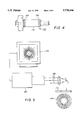
- FIG. 3 is a perspective view of the hydrodynamic ceramic bearing of the invention.
- FIG. 4 is a plan end view of a alternative hydrodynamic bearing assemblage having spiral pattern air channels formed in the shaft;
- FIG. 5 is a schematic of a device for forming a mask on a polyester sheet useful for engraving air channels in the hydrodynamic ceramic bearing of the invention.
- FIG. 6 is a schematic of a device for forming air channels having a predetermined pattern in a flange portion of the hydrodynamic ceramic bearing.
- ceramic powder comprising of primarily zirconium oxide, or a first concentration of particulate aluminum oxide and a second concentration of particulate zirconium oxide alloy is used for making hydrodynamic ceramic bearings, as discussed fully below.
- a typical hydrodynamic bearing 116 made in accordance with the method of the invention is illustrated in FIGS. 1 (Step F) and 3.
- the zirconium oxide alloy consists essentially of zirconium oxide and a secondary oxide selected from the group consisting of MgO, CaO, Y 2 O 3 , Sc 2 O 3 , and rare earth oxides.
- the zirconium oxide alloy has a concentration of the secondary oxide of, in the case of Y 2 O 3 , about 0.5 to about 5 mole percent; in the case of MgO, about 0.1 to about 1.0 mole percent, in the case of CeO 2 , about 0.5 to about 15 mole percent, in the case of Sc 2 O 3 , about 0.5 to about 7.0 mole percent and in the case of CaO from about 0.5 to about 5 mole percent, relative to the total of said zirconium oxide alloy, said compacting further comprising forming a blank.
- a mold is provided for receiving and processing the ceramic powder. The ceramic powder is then compacted (as described below) in the mold provided to form a ceramic billet.
- the ceramic billet is then shaped or green-machined so as to form a near net-shaped green ceramic bearing having opposing flange portions and a body portion between the opposing flange portions.
- the green ceramic bearing is sintered thereby forming a sintered net-shape ceramic bearing, as described more fully below.
- the ceramic bearing is then further machined or shaped, as indicated below.
- at least two air inlet ports are formed in the body portion of the bearing in fluid communications with air channels, having preferably a spiral pattern, formed in at least one flange portion of the bearing.
- step "A” diagrammatically illustrates the alloying process.
- Zirconia powder 100 is combined with one or more secondary oxide powders 102 to provide zirconia alloy powder 104.
- the preparation of zirconia alloys is well known to those skilled in the art and zirconia alloys are available commercially.
- particulate zirconia alloy having 3 mole percent Y 2 O 3 is marketed by Z-TECH Corporation, Bow, N.H., as "SYP-ULTRA 5.2 Yttria Stabilized Zirconia".
- tetragonal zirconia ceramic material for manufacturing a hydrodynamic bearing assemblage comprising either a stationary bearing/rotating shaft or a rotating bearing/stationary shaft in a cost effective way.
- the most preferred material which we prefer using is essentially zirconia having 100% tetragonal crystal structure.
- We developed this 100% tetragonal zirconia by alloying zirconia with a number of secondary oxides as described in U.S. Pat. Nos. 5,336,282 and 5,358,913, hereby incorporated herein by reference.
- the preferred ceramic powder mixture most preferred in the method of making zirconia-alumina composites of the invention includes a particulate alumina and particulate alloys of ZrO 2 and additional "secondary oxide" selected from: MgO, CaO, Y 2 O 3 , Sc 2 O 3 and Ce 2 O 3 and other rare earth oxides (also referred to herein as "Mg--Ca--Y--Sc-rare earth oxides").
- Zirconia alloys useful in the methods of the invention have a metastable tetragonal crystal structure in the temperature and pressure ranges at which the ceramic article produced will be used. For example, at temperatures up to about 200° C.
- zirconia alloys having, wherein zirconium oxide alloy has a concentration of said secondary oxide of, in the case of Y 2 O 3 , about 0.5 to about 5 mole percent; in the case of MgO, about 0.1 to about 1.0 mole percent, in the case of CeO 2 , about 0.5 to about 15 mole percent, in the case of Sc 2 O 3 , about 0.5 to about 7.0 mole percent and in the case of CaO from about 0.5 to about 5 mole percent, relative to the total of said zirconium oxide alloy, said compacting further comprising forming a blank, exhibit a tetragonal structure.
- Preferred oxides for alloying with zirconia are Y 2 O 3 , MgO, CaO, Ce 2 O 3 and combinations of these oxides. It is preferred that the zirconia powder have high purity, greater than about 99.9 percent.
- Specific examples of useful zirconia alloys include: tetragonal structure zirconia alloys having from about 2 to about 5 mole percent Y 2 O 3 , or more preferably about 3 mole percent Y 2 O 3 . Examples of tetragonal structure zirconia alloys useful in the methods of the invention are disclosed in U.S. Pat. No. 5,290,332.
- Such zirconia alloys are described in that patent as being useful to provide a "net-shape" ceramic article: a ceramic article that is dimensionally true after sintering and therefore does not necessitate further machining prior to use in its intended working environment.
- Step A' diagrammatically illustrates an alternative mixture of particulate zirconia alloy 104 and a particulate aluminum oxide 103.
- This alternative mixture can be achieved by mixing mechanically or chemically, for example, mixing by co-precipitation.
- the particulate mixture formed is from about 75 to 100 percent by weight (weight/total weight of particulate mixture) Al 2 O 3 , and preferably is from about 80 to about 99 percent by weight Al 2 O 3 , or more preferably is from about 80 to about 95 percent by weight Al 2 O 3 .
- grain and agglomeration sizes and distributions, moisture contents, and binders can be varied in both the alumina and the zirconia alloy, in a manner known to those skilled in the art.
- "Grain” is defined as an individual crystal, which may be within a particle, having a spatial orientation that is distinct from that of adjacent grains.
- "Agglomerate” is defined as an aggregation of individual particles, each of which may comprise multiple grains.
- the grain and agglomeration sizes and distributions, mad moisture contents of the alumina and the zirconia alloy are substantially the same and are selected as if the zirconia alloy was not going to be mixed with the alumina, that is in a manner known to the art to be suitable for the preparation of a zirconia alloy article.
- An example of convenient particulate characteristics for a particular embodiment of the invention is the following.
- Purity of ZrO 2 is preferably well controlled at 99.9 to 99.99 percent, that is, impurities are no more than about 0.1 to 0.01 percent.
- the grain size is from about 0.1 micrometers to about 0.6 micrometers.
- the average grain size is 0.3 micrometers.
- the distribution of grain sizes is 5-15 percent less than 0.1 micrometers, 40-60 percent less than 0.3 micrometers, and 85-95 percent less than 0.6 micrometers.
- the surface area of each individual grain ranges from about 10 to about 15 m 2 /gram or is preferably 14 m 2 /gram.
- Agglomerate size is from about 30 to about 60 micrometers and average agglomerate size is 40-60 micrometers.
- Moisture content is about 0.2 to 1.0 percent by volume of blank and is preferably 0.5 percent.
- the mixture of particulates is compacted in the presence of an organic binder.
- Step B binders such as gelatin or polyvinyl ionomer or more preferably polyvinyl alcohol, are added to and mixed with the particulate mixture Y-TZP, 104 or a composite mixture of Y-TZP and alumina, 103, both illustrated in Step A and A', respectively.
- This can be achieved preferably by spray drying or ball milling prior to placement of the mixture in a compacting device.
- Step “B” also illustrates an alternative mixing process known to those who are proficient in the art as “compounding” in which the particulate mixture or mixtures are mixed with greater than 20% by weight of an organic binder such as paraffin at a temperature higher than the glass transition temperature of such binder for subsequent injection molding process, illustrated as Step C'.
- compounding an alternative mixing process known to those who are proficient in the art as “compounding” in which the particulate mixture or mixtures are mixed with greater than 20% by weight of an organic binder such as paraffin at a temperature higher than the glass transition temperature of such binder for subsequent injection molding process, illustrated as Step C'.
- the particulate mixture 106 is cold compacted using preferably an isostatic press 150 to provide an unsintered blank 108 (FIG. 1).
- Unsintered blank 108 is alternatively referred to herein as a "green preform".
- the terms "cold compaction” and the like refer to compression of the particulate mixture at a temperature below glass transition or decomposition temperature of the organic binder.
- the green preform can be produced by such methods as cold uniaxial pressing, cold isostatic pressing, or cold extrusion.
- the particulate mixture is preferably subjected to uniform compacting forces in order to provide a unsintered blank which has a uniform density.
- near net-shape green blank 110' is generated using injection molding process.
- element 108 represents the product of both mixing and compaction, indicated by arrows " ⁇ B ⁇ & ⁇ C ⁇ ", respectively.
- Compaction and sintering are generally discussed herein as two consecutive operations, as indicated by steps "C” and "F", respectively, in FIG. 1, however, the invention is not limited to a particular sequence of compacting and sintering.
- compaction and sintering can be simultaneous in a single operation or partial compaction can be followed by sintering and further compaction.
- the interim product of compacting and sintering operations is referred to herein as a "blank", which is illustrated as element 108 in FIG. 1.
- Blank 108 is at least partially compacted and is either unsintered or not fully sintered.
- the powder is cold compacted to provide a "green preform", which has a "green" density that is substantially less than the final sintered density of the ceramic article 116. It is preferred that the green density be between about 40 and about 65 percent of the final sintered density, or more preferably be about 60 percent of the final sintered density.
- Step D near-net-shape bearing 110 is formed by green machining (as discussed below) of the blank 108 using carbide tools.
- spiral grooves 114 defining air channels are formed in flange portion 115 of net-shaped hydrodynamic bearing 110.
- the bearing 110 is sintered to full density using preferably sintering schedules described in U.S. Pat. Nos. 5,336,282 and 5,358,913, hereby incorporated herein by reference, and final precision machining were made to fight tolerances using diamond tools (FIG. 4).
- the air channels 114 on the flange portion 115 of the bearing assemblage (for stationary bearing/rotating shaft the air channels are either on two opposing bearing faces or on one bearing face; for rotating bearing/stationary shaft the air channels are on the shaft body) were formed or engraved in the green ceramic near-net-shaped bearing 110. While various methods of forming air channels in the sintered ceramic bearing may be used, we prefer a novel technique which we developed comprising bead blasting through a polyester mask (prepared for example by the technique illustrated in FIG. 5), as described in details below.
- Step F sintering of the green machined air bearing 110 is performed in a temperature range from about 1400° C. to about 1600° C., or more preferably about 1500° C. Preferable sintering times is in the range from about 1 hour to about 3 hours, or more preferably, about 2 hours. In a particular embodiment of the methods of the invention, the sintering peak temperature is 1500° C. and that temperature is maintained for about 2 hours. It is preferred that the pre-sintered bearing 110 be slowly heated to sintering temperature and slowly cooled so as to avoid undesirable dimensional changes, distortions and crack development.
- preferred temperature ramps during heating are: about 0.3° C./minute for room temperature to about 300° C., about 0.1° C./minute for about 300° C. to about 400° C., about 0.4° C./minute for about 400° C. to about 600° C., and about 1.5° C./minute for about 600° C. to about 1500° C.
- Preferred temperature ramps during cooling are: about 2° C./minute for about 1500° C. to about 800° C. and about 1.6° C./minute for about 800° C. to room temperature.
- sintering may be achieved in the presence of a dopant selected from: MgO, FeO, ZnO, NiO, and MnO, and combination thereof, as discussed below in detail.
- a dopant selected from: MgO, FeO, ZnO, NiO, and MnO, and combination thereof, as discussed below in detail.
- the resulting alumina-zirconia ceramic article of the invention has a core of ⁇ -alumina or ⁇ -alumina and tetragonal zirconia alloy and a case of cubic spinel or cubic spinel along with cubic structure or cubic and monoclinic structure of zirconia alloy.
- the dopant oxide selected from: MgO, FeO, ZnO, CoO, NiO, and MnO, and combination thereof is in contact with the blank. It is preferred that the sintering result in a ceramic article 116 having a "full" or nearly theoretical density, and it is more preferred that the density of the ceramic article 116 be from about 99.5 to about 99.9 percent of theoretical density. Sintering is conducted in air or other oxygen containing atmosphere.
- the methods of the invention are not limited to any particular sintering pressure and temperature conditions. Sintering can be performed at atmospheric pressure or alternatively a higher pressure can be used during all or part of the sintering to reduce porosity. The sintering is continued for a sufficient time period for the case of the article being sintered to reach a thermodynamic equilibrium structure.
- An example of a useful range of elevated sintering pressures is from about 69 MPa to about 207 MPa, or more preferably about 100-103 MPa.
- the exact manner in which the dopant is in contact with the blank during sintering is not critical, however, the "case", as that term is used herein, is limited to those areas of the blank in contact with the dopant during sintering.
- a cubic spinel and tetragonal zirconia case can be readily produced by the methods of the invention on a portion of the overall surface of an article. It is not critical that the dopant be in contact with the blank during initial sintering, that is, sintering which does not result in an increase in density to full density.
- the concentration of alumina in the blank 108 is from about 5 weight percent (relative to the total weight of zirconia and alumina) to about 50 weight percent, then the method of the invention produces an article having a case that is cubic spinel and tetragonal zirconia and a core that is ⁇ -alumina and tetragonal zirconia.
- dopant in effect, diffuses past tetragonal zirconia until all of the dopant has contacted and reacted, i.e. "partitioned", with alumina.
- the method of the invention produces an article that has a case that is substantially composed of cubic spinel and cubic zirconia or cubic and monoclinic zirconia and a core that is ⁇ -alumina and tetragonal zirconia.
- dopant does not, in effect, diffuse past tetragonal zirconia until all of the dopant has contacted and reacted with alumina; but rather reacts with alumina and tetragonal zirconia in the same vicinity, leaving alumina deeper within the blank unreacted.
- the part can be rigidly held by one of a numerous ways, including by simple mechanical gripping, by bonding or potting with a combination of beeswax and precision metal fixtures, the latter being preferred by the inventors.
- green machining can be accomplished in a variety of methods, including: turning, milling, drilling, form wheel grinding, and profile grinding. We prefer turning and profile grinding the billet during green machining to achieve the best results. Machining can be either dry or wet, depending on the binder present and whether or not the part has been bisque fired, i.e., fired at a high enough temperature to form bonds at particle-particle contact points, but not at a high enough temperature to produce densification.
- a further precision machining step F, according to FIG. 1, of some of the surfaces is required to meet dimensional tolerances, achieve improved surface finish or remove surface flaws. Maintaining dimensional tolerances to the extent of few millionths of an inch or achieving surface finish to less than 10 microinches is not possible unless final machining after sintering is undertaken. We accomplished dimensional tolerances to the extent of ⁇ 100 millionth of an inch using dry pressing (uniaxial pressing) for parts of simple geometry and controlling the shrinkage by our patented sintering process. Precision machining is required when the part demands tolerances in certain dimensions less than 100 millionth of an inch and also to meet some dimensional tolerances such as roundness, perpendicularity, parallelness, etc. As contrasted with green machining, final precision machining of the sintered ceramic bearing requires diamond tooling and also sophisticated machines. Skilled artisans would know that milling, grinding, lapping and polishing are some effective procedures which are used in precision machining.
- the air lubricated hydrodynamic ceramic bearing 116 of the invention comprises a generally cylindrical body 117 having a bore opening 119 therethrough and an interior wall 125 defining a bearing surface extending lengthwise through the bore opening 119.
- Air bearing 116 has at least two through holes 121 defining air inlet ports formed a circumferential portion of cylindrical body 117.
- a pair of end flange portions 115 are arranged on opposite ends of the generally cylindrical body 117. At least one of the end flange portions 115 have a spiral pattern air channels 114 formed therein in fluid communications with the at least two air inlet ports 121.
- air channels 114 can take any form and can be made by various techniques, we prefer using a bead blasting alumina grit through a polyester mask, as described below.
- a ceramic shaft is arranged in rotating contact with the bearing surface thereby forming an air lubricated hydrodynamic ceramic bearing assemblage.
- hydrodynamic bearing 116 of the invention is shown having spiral grooves 114 defining air channels arranged in at least one flange portion 115 in fluid communication with air inlet ports 121 formed in the body portion.
- the air channels 114 are formed on a flange portion 115 of the ceramic bearing 116 or, alternatively, air channels 134 may be formed on a circumferential portion 132 of ceramic shaft 130 (FIG. 4).
- the air channels are either on opposing faces of the bearing or on one bearing face as shown in FIG. 3.
- the air channels 134 are on the shaft body 132, as illustrated in FIG. 4.
- Air channels provide air flow across the bearing surface which lubricates the bearing-shaft assembly. While the number of air inlet ports 121 may depend on the application, generally we prefer minimally two air inlet ports 121 in the bearing.
- data processing equipment such as personal computer 160
- a CO 2 laser 162 is used to drive a CO 2 laser 162.
- polar coordinates r and ⁇ for the engraved spiral pattern in the ceramic article conform with the below empirical mathematical equation in which various values of x, y, r and ⁇ were used, as illustrated in Table 1.
- Table 1 According to the equation which defines the position of the leading edge E 1 of a spiral portion,
- ⁇ defines the position of a spirally engraved portion relative to the r; and, r defines the distance from the center of the x, y coordinates to the leading edge of a spirally engraved portion comprising the spiral pattern.
- a corresponding trailing edge E t of a spirally engraved portion is rotatably about 11.43° from its corresponding leading edge E 1 .
- the database profile for the preferred spiral pattern is inputted into a data processing system, such as personal computer 160, which communicates with the source of laser energy 162.
- Laser beams 163 from the source of laser energy 162 is then directed onto the polyester sheet 170 for engraving, in accordance with the database profile, the predetermined spiral pattern therein, thereby forming the polyester mask 164.
- Polyester mask 164 is then arranged in intimate contact using spray adhesive 166 (FIG. 6) with the ceramic article (or bearing) so as to avoid distortions in the spiral pattern imparted to the ceramic article.
- Alumina grits in a conventional sand blaster
- the blasting nozzle is held at about 14 to 16 inches from the workpiece.
- the process of sand blasting to abrade hard surfaces is common to those who are familiar with the art and the machines are available commercially.
- the hard alumina grits upon impinging on relatively more brittle surface than the plastic mask, removes the ceramic preferentially and thus forms the pattern.
- the plastic mask is so chosen such that it survives the very aggressive bead blasting process. We prefer either polyester or polyurethane sheets, thickness of which ranges from 5 to 10 mil. Other plastics like polycarbonate, mylar, etc. did not survive the rigor of grit blasting.
- the apparatus 180 for bead blasting includes a source 182 of ceramic grits 184, preferably alumina, a polyester mask 164 containing the spiral pattern 190, as described above.
- a plug 192 is arranged in a central opening (not shown) in the mask 164 and through the flange portion 115 and bearing body 117, as illustrated in FIG. 6.
- the apparatus 180 is substantially enclosed, with preferably a plastic shroud 119, to protect portions of the bearing 116 that are not being engraved by the alumina grits 184.
- Zirconia ceramic powder (prealloyed with secondary oxides described in U.S. Pat. Nos. 5,336,282 and 5,358,913) were packed and sealed in molds made of rubber/polyurethane of 55 to 70 durometers of Shore hardness A (preferably 65 durometers). These molds were cold isostatically pressed in an autoclave at 15 to 30 kpsi (preferably 25 kilo pounds per square inch) to obtain billets of appropriate sizes in diameter and length.
- zirconia alloy powder is premixed with polyvinyl alcohol binder.
- Preformed blanks produced by cold isostatically pressing are machined in their green state (i.e. before sintering) using carbide tools in lathe and milling machines.
- the cutting speeds in green machining of zirconia billets were maintained between 2800 and 3400 rpm (preferably at 32,000 rpm). In some cases, depending on the design, air inlet ports were drilled on the body of the bearings.
- Grooves defining air channels in the desired locations of the air bearing assembly were engraved by bead blasting through masks. The procedure for mask generation is illustrated in FIG. 5. Various plastic and metal masks were used to generate spiral pattern. Polyester and polyurethane masks performed the best to generate uniform spiral patterns on ceramic articles.
- the green machined and air channel engraved near-net-shaped air bearings are sintered following schedule described in U.S. Pat. Nos. 5,336,282 and 5,358,913. After sintering the bearings achieved full theoretical density of 6.05 gms/cc for yttria stabilized zirconia.
- the final precision machining of the bearing assembly and lapping of the flange portion containing the engraved spiral pattern were carried out using diamond tools.
- the surface finish of the bearing assembly including the air channels were ⁇ 0.1 microns.
Landscapes
- Engineering & Computer Science (AREA)
- General Engineering & Computer Science (AREA)
- Mechanical Engineering (AREA)
- Chemical & Material Sciences (AREA)
- Physics & Mathematics (AREA)
- Fluid Mechanics (AREA)
- Ceramic Engineering (AREA)
- Oil, Petroleum & Natural Gas (AREA)
- Compositions Of Oxide Ceramics (AREA)
- Magnetic Bearings And Hydrostatic Bearings (AREA)
- Sliding-Contact Bearings (AREA)
Abstract
Description
Φ=153.0649+176.4505 ln (r);
              TABLE 1
______________________________________
Coordinate No.
         x          y        r        Θ
______________________________________
 1       0.420000   0.000000 0.420000  0.0000
 2       0.430504   0.037956 0.432174  5.0386
 3       0.437682   0.076680 0.444348  9.9372
 4       0.441572   0.115872 0.456522 14.7034
 5       0.442236   0.155251 0.468696 19.3441
 6       0.439753   0.194558 0.480870 23.8659
 7       0.434217   0.233553 0.493043 28.2746
 8       0.425737   0.272016 0.505217 32.5757
 9       0.414430   0.309745 0.517391 36.7744
10       0.400422   0.346557 0.529565 40.8755
11       0.383847   0.382287 0.541739 44.8833
12       0.364841   0.416786 0.553913 48.8022
13       0.343547   0.449922 0.566087 52.6357
14       0.320107   0.481577 0.578261 56.3878
15       0.294667   0.511649 0.590435 60.0616
16       0.267371   0.540046 0.602609 63.6605
17       0.238363   0.566693 0.614783 67.1874
18       0.207785   0.591523 0.626957 70.6451
19       0.175779   0.614483 0.639130 74.0363
20       0.142482   0.635528 0.651304 77.3635
21       0.108030   0.654624 0.663478 80.6292
22       0.072555   0.671745 0.675652 83.8354
23       0.036185   0.686874 0.687826 86.9844
24       0.000954   0.699999 0.700000 90.0781
______________________________________
Claims (6)
Priority Applications (3)
| Application Number | Priority Date | Filing Date | Title |
|---|---|---|---|
| US08/701,944 US5738446A (en) | 1996-08-23 | 1996-08-23 | Air lubricated hydrodynamic ceramic bearings |
| EP97202479A EP0825355A3 (en) | 1996-08-23 | 1997-08-11 | Air lubricated hydrodynamic ceramic bearings |
| JP9226847A JPH1082421A (en) | 1996-08-23 | 1997-08-22 | Air lubricating system fluid dynamical bearing assembly |
Applications Claiming Priority (1)
| Application Number | Priority Date | Filing Date | Title |
|---|---|---|---|
| US08/701,944 US5738446A (en) | 1996-08-23 | 1996-08-23 | Air lubricated hydrodynamic ceramic bearings |
Publications (1)
| Publication Number | Publication Date |
|---|---|
| US5738446A true US5738446A (en) | 1998-04-14 |
Family
ID=24819312
Family Applications (1)
| Application Number | Title | Priority Date | Filing Date |
|---|---|---|---|
| US08/701,944 Expired - Lifetime US5738446A (en) | 1996-08-23 | 1996-08-23 | Air lubricated hydrodynamic ceramic bearings |
Country Status (3)
| Country | Link |
|---|---|
| US (1) | US5738446A (en) |
| EP (1) | EP0825355A3 (en) |
| JP (1) | JPH1082421A (en) |
Cited By (9)
| Publication number | Priority date | Publication date | Assignee | Title |
|---|---|---|---|---|
| US5926342A (en) * | 1995-11-20 | 1999-07-20 | Sankyo Seiki Mfg. Co., Ltd. | Air dynamic pressure bearing apparatus and data drive apparatus using the same |
| WO2000004304A1 (en) * | 1998-07-15 | 2000-01-27 | Nanomotion, Inc. | Sample stage including a slider assembly |
| US6201328B1 (en) * | 1995-03-31 | 2001-03-13 | Matsushita Electric Industrial Co., Ltd. | Spindle motor having an etched thrust plate and a process of making the spindle motor by etching of the thrust plate |
| US6254348B1 (en) * | 1999-04-19 | 2001-07-03 | Richard Lee | Structure of a radiating fan |
| US6260770B1 (en) | 1998-07-13 | 2001-07-17 | Dan Mamtirim | Sprinkler and sealing assembly therefor |
| US6402383B1 (en) * | 1999-02-25 | 2002-06-11 | Seagate Technology, Llc | Design methods for highly efficient high speed fluid dynamic bearing motors |
| US7956499B2 (en) | 2005-06-02 | 2011-06-07 | Seagate Technology Llc | Motor magnetic force attenuator |
| US9694102B2 (en) | 2003-03-07 | 2017-07-04 | Louis A. Serafin, Jr. Trust | Ceramic manufactures |
| US10232388B2 (en) | 2017-03-08 | 2019-03-19 | NaanDanJain Irrigation Ltd. | Multiple orientation rotatable sprinkler |
Families Citing this family (1)
| Publication number | Priority date | Publication date | Assignee | Title |
|---|---|---|---|---|
| CN108916230B (en) * | 2018-02-06 | 2020-10-27 | 西安交通大学 | A helical throttle hydrostatic gas bearing |
Citations (12)
| Publication number | Priority date | Publication date | Assignee | Title |
|---|---|---|---|---|
| US2624097A (en) * | 1951-01-09 | 1953-01-06 | Norton Co | Method of making dense, hard, abrasion resistant ceramic articles |
| US3721480A (en) * | 1968-10-15 | 1973-03-20 | Aerostatic Ltd | Gas bearing assembly |
| US4728201A (en) * | 1986-12-17 | 1988-03-01 | Kurt Manufacturing Company, Inc. | Low velocity energized gas particle bearing |
| US4754494A (en) * | 1985-07-18 | 1988-06-28 | The Charles Stark Draper Laboratory, Inc. | Beryllium based, wear-resistant material for bearings and the like |
| US4759644A (en) * | 1986-09-30 | 1988-07-26 | Ngk Spark Plug Co., Ltd. | Gas bearing body |
| US4883367A (en) * | 1987-04-30 | 1989-11-28 | Matsushita Electric Industrial Co., Ltd. | Bearing unit |
| US4884899A (en) * | 1987-04-03 | 1989-12-05 | Schwartzman Everett H | Resiliently mounted fluid bearing assembly |
| US5076716A (en) * | 1983-07-06 | 1991-12-31 | Ebara Corporation | Thrust bearing with spiral grooved face |
| US5083873A (en) * | 1989-10-02 | 1992-01-28 | Wing Highcera Co., Ltd. | Ceramic bearing |
| US5224782A (en) * | 1990-10-25 | 1993-07-06 | Ebara Corporation | Hydrodynamic bearing |
| US5336282A (en) * | 1991-12-31 | 1994-08-09 | Eastman Kodak Company | Zirconia ceramics and a process of producing the same |
| US5358913A (en) * | 1992-03-05 | 1994-10-25 | Eastman Kodak Company | Zirconia ceramic articles having a tetragonal core and cubic casing |
Family Cites Families (6)
| Publication number | Priority date | Publication date | Assignee | Title |
|---|---|---|---|---|
| GB1310526A (en) * | 1969-05-14 | 1973-03-21 | Smiths Industries Ltd | Gas-lubricated bearings |
| JPS58114803A (en) * | 1981-12-28 | 1983-07-08 | Toshiba Tungaloy Co Ltd | Rotary driving device for small diameter-drill etc. |
| EP0587906B1 (en) * | 1992-03-31 | 2001-08-01 | Sumitomo Electric Industries, Ltd. | Sliding member and production thereof |
| JPH0668439A (en) * | 1992-08-20 | 1994-03-11 | Ebara Corp | Drum motor for vtr |
| EP0603818B1 (en) | 1992-12-22 | 1996-07-31 | Eastman Kodak Company | Method of preparation of zirconia articles having tetragonal cores and monoclinic cases |
| JPH06351209A (en) * | 1993-06-08 | 1994-12-22 | Ibiden Co Ltd | Brushless motor |
-
1996
- 1996-08-23 US US08/701,944 patent/US5738446A/en not_active Expired - Lifetime
-
1997
- 1997-08-11 EP EP97202479A patent/EP0825355A3/en not_active Ceased
- 1997-08-22 JP JP9226847A patent/JPH1082421A/en active Pending
Patent Citations (12)
| Publication number | Priority date | Publication date | Assignee | Title |
|---|---|---|---|---|
| US2624097A (en) * | 1951-01-09 | 1953-01-06 | Norton Co | Method of making dense, hard, abrasion resistant ceramic articles |
| US3721480A (en) * | 1968-10-15 | 1973-03-20 | Aerostatic Ltd | Gas bearing assembly |
| US5076716A (en) * | 1983-07-06 | 1991-12-31 | Ebara Corporation | Thrust bearing with spiral grooved face |
| US4754494A (en) * | 1985-07-18 | 1988-06-28 | The Charles Stark Draper Laboratory, Inc. | Beryllium based, wear-resistant material for bearings and the like |
| US4759644A (en) * | 1986-09-30 | 1988-07-26 | Ngk Spark Plug Co., Ltd. | Gas bearing body |
| US4728201A (en) * | 1986-12-17 | 1988-03-01 | Kurt Manufacturing Company, Inc. | Low velocity energized gas particle bearing |
| US4884899A (en) * | 1987-04-03 | 1989-12-05 | Schwartzman Everett H | Resiliently mounted fluid bearing assembly |
| US4883367A (en) * | 1987-04-30 | 1989-11-28 | Matsushita Electric Industrial Co., Ltd. | Bearing unit |
| US5083873A (en) * | 1989-10-02 | 1992-01-28 | Wing Highcera Co., Ltd. | Ceramic bearing |
| US5224782A (en) * | 1990-10-25 | 1993-07-06 | Ebara Corporation | Hydrodynamic bearing |
| US5336282A (en) * | 1991-12-31 | 1994-08-09 | Eastman Kodak Company | Zirconia ceramics and a process of producing the same |
| US5358913A (en) * | 1992-03-05 | 1994-10-25 | Eastman Kodak Company | Zirconia ceramic articles having a tetragonal core and cubic casing |
Cited By (11)
| Publication number | Priority date | Publication date | Assignee | Title |
|---|---|---|---|---|
| US6201328B1 (en) * | 1995-03-31 | 2001-03-13 | Matsushita Electric Industrial Co., Ltd. | Spindle motor having an etched thrust plate and a process of making the spindle motor by etching of the thrust plate |
| US5926342A (en) * | 1995-11-20 | 1999-07-20 | Sankyo Seiki Mfg. Co., Ltd. | Air dynamic pressure bearing apparatus and data drive apparatus using the same |
| US6260770B1 (en) | 1998-07-13 | 2001-07-17 | Dan Mamtirim | Sprinkler and sealing assembly therefor |
| WO2000004304A1 (en) * | 1998-07-15 | 2000-01-27 | Nanomotion, Inc. | Sample stage including a slider assembly |
| US6193199B1 (en) * | 1998-07-15 | 2001-02-27 | Nanomotion, Inc. | Sample stage including a slider assembly |
| US6402383B1 (en) * | 1999-02-25 | 2002-06-11 | Seagate Technology, Llc | Design methods for highly efficient high speed fluid dynamic bearing motors |
| US6254348B1 (en) * | 1999-04-19 | 2001-07-03 | Richard Lee | Structure of a radiating fan |
| US9694102B2 (en) | 2003-03-07 | 2017-07-04 | Louis A. Serafin, Jr. Trust | Ceramic manufactures |
| US7956499B2 (en) | 2005-06-02 | 2011-06-07 | Seagate Technology Llc | Motor magnetic force attenuator |
| US10232388B2 (en) | 2017-03-08 | 2019-03-19 | NaanDanJain Irrigation Ltd. | Multiple orientation rotatable sprinkler |
| US10239067B2 (en) | 2017-03-08 | 2019-03-26 | NaanDanJain Irrigation Ltd. | Multiple orientation rotatable sprinkler |
Also Published As
| Publication number | Publication date |
|---|---|
| EP0825355A3 (en) | 1998-11-18 |
| EP0825355A2 (en) | 1998-02-25 |
| JPH1082421A (en) | 1998-03-31 |
Similar Documents
| Publication | Publication Date | Title |
|---|---|---|
| US5776408A (en) | Method of engraving green ceramic articles | |
| US5730928A (en) | Method of making air lubricated hydrodynamic ceramic bearings | |
| US5824123A (en) | Zirconia articles having tetragonal cores and monoclinic cases and preparation and sintering methods | |
| US5358913A (en) | Zirconia ceramic articles having a tetragonal core and cubic casing | |
| US5738446A (en) | Air lubricated hydrodynamic ceramic bearings | |
| US4650774A (en) | Magnetic head slider material | |
| US5672302A (en) | In-situ surface nitridation of zirconia ceramics | |
| US5795362A (en) | Alumina ceramic articles having cubic spinel on surfaces and methods for preparing alumina ceramic articles and for sintering | |
| EP0824989A2 (en) | Method of forming a mask useful for engraving ceramic articles | |
| EP0825158A2 (en) | Core shell structured articles based on alumina ceramics and having spinel surfaces | |
| US5696040A (en) | Ceramic article containing a core comprising zirconia and a shell comprising zirconium boride | |
| US5820960A (en) | Thin zirconia disk substrate | |
| US5679611A (en) | Ceramic article containing a core comprising tetragonal zirconia and a shell comprising zirconium nitride | |
| US6164846A (en) | Apparatus and method for transporting a web | |
| US5702766A (en) | Process of forming a ceramic article containing a core comprising zirconia and a shell comprising zirconium boride | |
| JP2836866B2 (en) | Ceramic-SiC-molybdenum disulfide-based composite material and its sliding parts | |
| EP0869296A2 (en) | Apparatus and method for spooling strips of web | |
| JP2610381B2 (en) | Manufacturing method of ceramic parts with pores using firing bonding | |
| JPH05105510A (en) | Ceramic material | |
| JPH02149465A (en) | High-strength ceramic sintered body for tool | |
| JPH10128600A (en) | Material carrying element |
Legal Events
| Date | Code | Title | Description |
|---|---|---|---|
| AS | Assignment |
Owner name: EASTMAN KODAK COMPANY, NEW YORK Free format text: ASSIGNMENT OF ASSIGNORS INTEREST;ASSIGNORS:GHOSH, SYAMAL K.;CHATTERJEE, DILIP K.;KOLB, THEODORE R.;REEL/FRAME:008169/0205 Effective date: 19960823 |
|
| FEPP | Fee payment procedure |
Free format text: PAYOR NUMBER ASSIGNED (ORIGINAL EVENT CODE: ASPN); ENTITY STATUS OF PATENT OWNER: LARGE ENTITY |
|
| STCF | Information on status: patent grant |
Free format text: PATENTED CASE |
|
| FPAY | Fee payment |
Year of fee payment: 4 |
|
| FEPP | Fee payment procedure |
Free format text: PAYER NUMBER DE-ASSIGNED (ORIGINAL EVENT CODE: RMPN); ENTITY STATUS OF PATENT OWNER: LARGE ENTITY Free format text: PAYOR NUMBER ASSIGNED (ORIGINAL EVENT CODE: ASPN); ENTITY STATUS OF PATENT OWNER: LARGE ENTITY |
|
| FPAY | Fee payment |
Year of fee payment: 8 |
|
| FPAY | Fee payment |
Year of fee payment: 12 |
|
| AS | Assignment |
Owner name: CITICORP NORTH AMERICA, INC., AS AGENT, NEW YORK Free format text: SECURITY INTEREST;ASSIGNORS:EASTMAN KODAK COMPANY;PAKON, INC.;REEL/FRAME:028201/0420 Effective date: 20120215 |
|
| AS | Assignment |
Owner name: WILMINGTON TRUST, NATIONAL ASSOCIATION, AS AGENT, Free format text: PATENT SECURITY AGREEMENT;ASSIGNORS:EASTMAN KODAK COMPANY;PAKON, INC.;REEL/FRAME:030122/0235 Effective date: 20130322 Owner name: WILMINGTON TRUST, NATIONAL ASSOCIATION, AS AGENT, MINNESOTA Free format text: PATENT SECURITY AGREEMENT;ASSIGNORS:EASTMAN KODAK COMPANY;PAKON, INC.;REEL/FRAME:030122/0235 Effective date: 20130322 |
|
| AS | Assignment |
Owner name: JPMORGAN CHASE BANK, N.A., AS ADMINISTRATIVE, DELAWARE Free format text: INTELLECTUAL PROPERTY SECURITY AGREEMENT (FIRST LIEN);ASSIGNORS:EASTMAN KODAK COMPANY;FAR EAST DEVELOPMENT LTD.;FPC INC.;AND OTHERS;REEL/FRAME:031158/0001 Effective date: 20130903 Owner name: BARCLAYS BANK PLC, AS ADMINISTRATIVE AGENT, NEW YORK Free format text: INTELLECTUAL PROPERTY SECURITY AGREEMENT (SECOND LIEN);ASSIGNORS:EASTMAN KODAK COMPANY;FAR EAST DEVELOPMENT LTD.;FPC INC.;AND OTHERS;REEL/FRAME:031159/0001 Effective date: 20130903 Owner name: BARCLAYS BANK PLC, AS ADMINISTRATIVE AGENT, NEW YO Free format text: INTELLECTUAL PROPERTY SECURITY AGREEMENT (SECOND LIEN);ASSIGNORS:EASTMAN KODAK COMPANY;FAR EAST DEVELOPMENT LTD.;FPC INC.;AND OTHERS;REEL/FRAME:031159/0001 Effective date: 20130903 Owner name: JPMORGAN CHASE BANK, N.A., AS ADMINISTRATIVE, DELA Free format text: INTELLECTUAL PROPERTY SECURITY AGREEMENT (FIRST LIEN);ASSIGNORS:EASTMAN KODAK COMPANY;FAR EAST DEVELOPMENT LTD.;FPC INC.;AND OTHERS;REEL/FRAME:031158/0001 Effective date: 20130903 Owner name: EASTMAN KODAK COMPANY, NEW YORK Free format text: RELEASE OF SECURITY INTEREST IN PATENTS;ASSIGNORS:CITICORP NORTH AMERICA, INC., AS SENIOR DIP AGENT;WILMINGTON TRUST, NATIONAL ASSOCIATION, AS JUNIOR DIP AGENT;REEL/FRAME:031157/0451 Effective date: 20130903 Owner name: PAKON, INC., NEW YORK Free format text: RELEASE OF SECURITY INTEREST IN PATENTS;ASSIGNORS:CITICORP NORTH AMERICA, INC., AS SENIOR DIP AGENT;WILMINGTON TRUST, NATIONAL ASSOCIATION, AS JUNIOR DIP AGENT;REEL/FRAME:031157/0451 Effective date: 20130903 Owner name: BANK OF AMERICA N.A., AS AGENT, MASSACHUSETTS Free format text: INTELLECTUAL PROPERTY SECURITY AGREEMENT (ABL);ASSIGNORS:EASTMAN KODAK COMPANY;FAR EAST DEVELOPMENT LTD.;FPC INC.;AND OTHERS;REEL/FRAME:031162/0117 Effective date: 20130903 |
|
| AS | Assignment |
Owner name: EASTMAN KODAK COMPANY, NEW YORK Free format text: RELEASE BY SECURED PARTY;ASSIGNOR:BARCLAYS BANK PLC;REEL/FRAME:041656/0531 Effective date: 20170202 |
|
| AS | Assignment |
Owner name: KODAK AMERICAS, LTD., NEW YORK Free format text: RELEASE BY SECURED PARTY;ASSIGNOR:JP MORGAN CHASE BANK, N.A., AS ADMINISTRATIVE AGENT;REEL/FRAME:049814/0001 Effective date: 20190617 Owner name: KODAK PHILIPPINES, LTD., NEW YORK Free format text: RELEASE BY SECURED PARTY;ASSIGNOR:JP MORGAN CHASE BANK, N.A., AS ADMINISTRATIVE AGENT;REEL/FRAME:049814/0001 Effective date: 20190617 Owner name: FAR EAST DEVELOPMENT LTD., NEW YORK Free format text: RELEASE BY SECURED PARTY;ASSIGNOR:JP MORGAN CHASE BANK, N.A., AS ADMINISTRATIVE AGENT;REEL/FRAME:049814/0001 Effective date: 20190617 Owner name: KODAK IMAGING NETWORK, INC., NEW YORK Free format text: RELEASE BY SECURED PARTY;ASSIGNOR:JP MORGAN CHASE BANK, N.A., AS ADMINISTRATIVE AGENT;REEL/FRAME:049814/0001 Effective date: 20190617 Owner name: QUALEX, INC., NEW YORK Free format text: RELEASE BY SECURED PARTY;ASSIGNOR:JP MORGAN CHASE BANK, N.A., AS ADMINISTRATIVE AGENT;REEL/FRAME:049814/0001 Effective date: 20190617 Owner name: KODAK (NEAR EAST), INC., NEW YORK Free format text: RELEASE BY SECURED PARTY;ASSIGNOR:JP MORGAN CHASE BANK, N.A., AS ADMINISTRATIVE AGENT;REEL/FRAME:049814/0001 Effective date: 20190617 Owner name: KODAK REALTY, INC., NEW YORK Free format text: RELEASE BY SECURED PARTY;ASSIGNOR:JP MORGAN CHASE BANK, N.A., AS ADMINISTRATIVE AGENT;REEL/FRAME:049814/0001 Effective date: 20190617 Owner name: LASER PACIFIC MEDIA CORPORATION, NEW YORK Free format text: RELEASE BY SECURED PARTY;ASSIGNOR:JP MORGAN CHASE BANK, N.A., AS ADMINISTRATIVE AGENT;REEL/FRAME:049814/0001 Effective date: 20190617 Owner name: KODAK AVIATION LEASING LLC, NEW YORK Free format text: RELEASE BY SECURED PARTY;ASSIGNOR:JP MORGAN CHASE BANK, N.A., AS ADMINISTRATIVE AGENT;REEL/FRAME:049814/0001 Effective date: 20190617 Owner name: CREO MANUFACTURING AMERICA LLC, NEW YORK Free format text: RELEASE BY SECURED PARTY;ASSIGNOR:JP MORGAN CHASE BANK, N.A., AS ADMINISTRATIVE AGENT;REEL/FRAME:049814/0001 Effective date: 20190617 Owner name: PAKON, INC., NEW YORK Free format text: RELEASE BY SECURED PARTY;ASSIGNOR:JP MORGAN CHASE BANK, N.A., AS ADMINISTRATIVE AGENT;REEL/FRAME:049814/0001 Effective date: 20190617 Owner name: NPEC, INC., NEW YORK Free format text: RELEASE BY SECURED PARTY;ASSIGNOR:JP MORGAN CHASE BANK, N.A., AS ADMINISTRATIVE AGENT;REEL/FRAME:049814/0001 Effective date: 20190617 Owner name: EASTMAN KODAK COMPANY, NEW YORK Free format text: RELEASE BY SECURED PARTY;ASSIGNOR:JP MORGAN CHASE BANK, N.A., AS ADMINISTRATIVE AGENT;REEL/FRAME:049814/0001 Effective date: 20190617 Owner name: FPC, INC., NEW YORK Free format text: RELEASE BY SECURED PARTY;ASSIGNOR:JP MORGAN CHASE BANK, N.A., AS ADMINISTRATIVE AGENT;REEL/FRAME:049814/0001 Effective date: 20190617 Owner name: KODAK PORTUGUESA LIMITED, NEW YORK Free format text: RELEASE BY SECURED PARTY;ASSIGNOR:JP MORGAN CHASE BANK, N.A., AS ADMINISTRATIVE AGENT;REEL/FRAME:049814/0001 Effective date: 20190617 |
|
| AS | Assignment |
Owner name: KODAK (NEAR EAST) INC., NEW YORK Free format text: RELEASE BY SECURED PARTY;ASSIGNOR:BARCLAYS BANK PLC;REEL/FRAME:052773/0001 Effective date: 20170202 Owner name: KODAK PHILIPPINES LTD., NEW YORK Free format text: RELEASE BY SECURED PARTY;ASSIGNOR:BARCLAYS BANK PLC;REEL/FRAME:052773/0001 Effective date: 20170202 Owner name: LASER PACIFIC MEDIA CORPORATION, NEW YORK Free format text: RELEASE BY SECURED PARTY;ASSIGNOR:BARCLAYS BANK PLC;REEL/FRAME:052773/0001 Effective date: 20170202 Owner name: QUALEX INC., NEW YORK Free format text: RELEASE BY SECURED PARTY;ASSIGNOR:BARCLAYS BANK PLC;REEL/FRAME:052773/0001 Effective date: 20170202 Owner name: NPEC INC., NEW YORK Free format text: RELEASE BY SECURED PARTY;ASSIGNOR:BARCLAYS BANK PLC;REEL/FRAME:052773/0001 Effective date: 20170202 Owner name: KODAK REALTY INC., NEW YORK Free format text: RELEASE BY SECURED PARTY;ASSIGNOR:BARCLAYS BANK PLC;REEL/FRAME:052773/0001 Effective date: 20170202 Owner name: FPC INC., NEW YORK Free format text: RELEASE BY SECURED PARTY;ASSIGNOR:BARCLAYS BANK PLC;REEL/FRAME:052773/0001 Effective date: 20170202 Owner name: KODAK AMERICAS LTD., NEW YORK Free format text: RELEASE BY SECURED PARTY;ASSIGNOR:BARCLAYS BANK PLC;REEL/FRAME:052773/0001 Effective date: 20170202 Owner name: EASTMAN KODAK COMPANY, NEW YORK Free format text: RELEASE BY SECURED PARTY;ASSIGNOR:BARCLAYS BANK PLC;REEL/FRAME:052773/0001 Effective date: 20170202 Owner name: FAR EAST DEVELOPMENT LTD., NEW YORK Free format text: RELEASE BY SECURED PARTY;ASSIGNOR:BARCLAYS BANK PLC;REEL/FRAME:052773/0001 Effective date: 20170202 |