US5738430A - Method and apparatus for predicting retinal illuminance - Google Patents
Method and apparatus for predicting retinal illuminance Download PDFInfo
- Publication number
- US5738430A US5738430A US08/693,725 US69372596A US5738430A US 5738430 A US5738430 A US 5738430A US 69372596 A US69372596 A US 69372596A US 5738430 A US5738430 A US 5738430A
- Authority
- US
- United States
- Prior art keywords
- pupil diameter
- sup
- luminance
- pixel
- evaluating
- Prior art date
- Legal status (The legal status is an assumption and is not a legal conclusion. Google has not performed a legal analysis and makes no representation as to the accuracy of the status listed.)
- Expired - Lifetime
Links
Images

Classifications
-
- A—HUMAN NECESSITIES
- A61—MEDICAL OR VETERINARY SCIENCE; HYGIENE
- A61B—DIAGNOSIS; SURGERY; IDENTIFICATION
- A61B3/00—Apparatus for testing the eyes; Instruments for examining the eyes
- A61B3/10—Objective types, i.e. instruments for examining the eyes independent of the patients' perceptions or reactions
- A61B3/11—Objective types, i.e. instruments for examining the eyes independent of the patients' perceptions or reactions for measuring interpupillary distance or diameter of pupils
- A61B3/112—Objective types, i.e. instruments for examining the eyes independent of the patients' perceptions or reactions for measuring interpupillary distance or diameter of pupils for measuring diameter of pupils
Definitions
- the invention relates to image compression systems and, more particularly, to a method and apparatus for predicting retinal illuminance from luminance distributions for use in a quality-based image processing or compression system.
- Image compression systems such as those systems based upon the Moving Pictures Experts Group (MPEG) standards, are generally lossy in that the image quality of the decoded image is degraded as compared to the original input image to the system.
- the visual perception of image degradation due to lossy compression depends on retinal illuminance from light produced by the various pixels within the decoded image. At low enough retinal illuminance, for example, all artifacts within the decoded image become invisible. Because the retinal illuminance of a pixel is the product of a measured pixel luminance and the pupil area of the eye, the pupil diameter enters implicitly into any computations involving visual quality of a display. However, conventional compression systems do not compensate for retinal illuminance. Furthermore, compression systems that use an image quality metric to control the compression process generally utilize a fixed pupil diameter.
- a fixed pupil diameter of approximately 2 mm is used to facilitate conversion from pixel luminance to retinal illuminance.
- the pupil diameter during image viewing can be as large as 8 or 9 mm.
- the method and apparatus of the present invention predicts how any given spatio-temporal light distribution would change an observer's pupil diameter.
- the light distribution is a pixel luminance distribution for an image or image sequence as portrayed upon a display screen, e.g., video monitor.
- the method of the present invention computes the instantaneous effect of luminance driving the pupil diameter, the cumulative driving function of the pupil diameter, and the evolving pupil diameter using a modified Trezona formula. Using the evolving pupil diameter together with the image luminance distribution, the method computes the retinal illuminance for the given input luminance distribution. Thus, for a given image, the invention predicts the light distribution upon an observer's retina.
- FIG. 1 depicts a block diagram of a general purpose computer that is programmed to execute the method of the present invention.
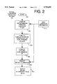
- FIG. 2 depicts a flow diagram of the method of the present invention.
- FIG. 1 depicts a block diagram of a general purpose computer system that, when executing a retinal illuminance prediction routine in accordance with the present invention, becomes a retinal illuminance prediction system 100 operating in accordance with the inventive method.
- the system contains a luminance information source 102, a computer system 104, one or more output devices 106 and one or more input devices 108.
- the luminance information source 102 provides a luminance distribution for each video frame in a video sequence, i.e., a luminance distribution L(x,y,t).
- This luminance information includes a luminance value for each pixel location (x,y) within an image, i.e., the information is a spacial distribution within each image frame and a spatio-temporal distribution over a sequence of frames in a video image sequence.
- This luminance information is available via a look-up table containing digital pixel values used to drive a calibrated display monitor.
- the luminance information is directly measured as a general display monitor generates light from the pixels displayed on a display monitor.
- the measuring device produces an array of luminance Values representing the luminance at particular locations on the display monitor's surface.
- the general purpose computer 104 facilitates computation of the retinal illumination for a given luminance distribution.
- the computer system contains a data buffer 110, a central processing unit (CPU) 112, support circuitry 114, random access memory (RAM) 116, read only memory (ROM) 118, and a display driver 120.
- a user interacts with the system through one or more input devices 108 such as a keyboard, mouse, trackball, touchpad, and the like.
- the computer system utilizing the inventive method displays information and various graphical interface displays on the output display device 106 such as a computer monitor.
- the computer system may also interact with other output display devices such as a printer to provide a hard copy of any display that appears on the computer monitor.
- the data buffer 110 provides data rate equalization (frame buffering) between the luminance information source and the CPU.
- this buffer is a first-in, first-out (FIFO) buffer.
- FIFO first-in, first-out
- Such buffers are typically used to provide a constant data rate to the CPU while providing flexibility in the data rates that can be generated by the luminance information source.
- the CPU 112 is typically a general purpose processor such as a Power PC, Pentium, or some other generally available processor.
- Power PC is a registered trademark of International Business Machines, Armonk, N.Y.
- Pentlure is a registered trademark of the Intel Corporation, Santa Clara, Calif. Since the software implementation of the present invention is not required to execute on any specific processor, the routines of the present invention can be executed on any type Of processor or combination of processors in a parallel processing computer environment.
- the method for retinal illumination computation may be accomplished within an image processing system or a video compression circuit.
- the CPU 112 operates in conjunction with various other circuits such as RAM 116, ROM 118 and support circuitry 114 such as co-processors, clock circuits, cache, power supplies and other well known circuits.
- RAM 116 random access memory
- ROM 118 read-only memory
- support circuitry 114 such as co-processors, clock circuits, cache, power supplies and other well known circuits.
- the operation and interrelationship of various computer components is well known in the art and does not require further explanation.
- the display driver 120 may be a video card, printer, driver or other common driver software or hardware as required by the object devices 106.
- the RAM 116 stores the software implementation of the present invention.
- the routines of the invention are stored in a mass storage device 119 and recalled into temporary storage in RAM 116 when executed by the CPU 112.
- the invention is implemented as the retinal illumination prediction routine 122.
- routine 122 is executed by the computer.
- FIG. 2 depicts a flow diagram of routine 122.
- the routine begins at step 200 and proceeds to step 202, where the routine computes the instantaneous effective luminance (cL) eff (t) driving the pupil diameter of a virtual observer of a display producing a luminance distribution, using:
- D is the viewing distance from the virtual observer to an image
- L(x,y,t) is the luminance of each pixel in the image as provided by step 212.
- g is the open-loop pupil-response function as substantially defined in L. Stark, "Neurological Control Systems: Studies in Bioengineering, Plenum, N.Y., 1968, pp.77-91. Therein, g(t) is defined as
- the routine computes the evolving pupil diameter d(t) using a modified Trezona formula
- Trezona formula is disclosed in P.W. Trezona, "Luminance Level Conversions to Assist Lighting Engineers To Use Fundamental Visual Data", Lighting Research and Technology, 15, pp. 83-88 (1983).
- the routine predicts, at step 208, the retinal illuminance B(x,y,t) using the pupil diameter d(t) of Equation 4 and the luminance information L(x,y,t) provided by the luminance information source.
- the result is a prediction of the retinal illuminance resulting from a given luminance distribution.
- the predicted value is made available at step 210 for various applications.
- the retinal illuminance value finds use in such applications as quality-based image processing and compression.
- decoded image quality controls how the image is processed or compressed.
- the quality measure generally relies upon a retinal illumination parameter.
- One such system that uses a spatio-temporal "just noticeable differences" quality model is disclosed in U.S. Pat. application Ser. No. 08/668,015, filed Jun. 17, 1996, and incorporated herein by reference.
- a quality-based compression system is disclosed in U.S. Pat. application Ser. No. 60/014,272, filed Mar. 29, 1996, and incorporated herein by reference.
- the foregoing computations can be simplified to facilitate numerical analysis.
- the integration is replaced with a summation over the image pixels, under the assumption that there is no appreciable luminance outside the image area.
- the geometric function, (x 2 +y 2 ) 0 .5 is computed prior to executing routine 122 in processing a complete sequence of image frames t, where t is quantized in units of one inter-frame interval. Since this function does not change with time (e.g., from frame to frame), the function is computed once for all x and y. Then the values are stored in memory for retrieval and use in processing each new image frame.
- the convolution in step 204 involves computing ##EQU1## which is approximated by a summation of (cL) cntrl (j) using a time index j and a time step dt.
- the quantity dt is conveniently chosen as 1/30 of a second (the video frame rate) or 1/60 of a second (the video interlace-field rate).
- the short duration g(t) requires modeling the time waveform q(t) of the frame as each frame turns on and off. To simplify the computation, the time required to excite a pixel and the time required for a pixel to cease emitting light is ignored, i.e., the emission period is approximated as a step function.
- the image sequence (cL) eff (t) is then represented as ##EQU2## where I D and (k dt) are computed values of (cL) eff (t) at each frame time.
- Equation 8 the infinite limits of Equation 8 are replaced with finite limits imposed by the effective duration of H( ⁇ ).
- a digital implementation of the retinal illumination prediction routine uses Equation 10, 11, and 13.
- step 204 can be implemented using an FIR or IIR filter.
Landscapes
- Life Sciences & Earth Sciences (AREA)
- Health & Medical Sciences (AREA)
- Medical Informatics (AREA)
- Biophysics (AREA)
- Ophthalmology & Optometry (AREA)
- Engineering & Computer Science (AREA)
- Biomedical Technology (AREA)
- Heart & Thoracic Surgery (AREA)
- Physics & Mathematics (AREA)
- Molecular Biology (AREA)
- Surgery (AREA)
- Animal Behavior & Ethology (AREA)
- General Health & Medical Sciences (AREA)
- Public Health (AREA)
- Veterinary Medicine (AREA)
- Eye Examination Apparatus (AREA)
- Photometry And Measurement Of Optical Pulse Characteristics (AREA)
Abstract
Description
(cL).sub.eff (t)=5.7037 D.sup.-3 ∫dxdyL(x,y,t)(x.sup.2 +y.sup.2).sup.0.5, (1)
(cL).sub.cntrl (t)=∫dt'g(t-t')(cL).sub.eff (t'), (2)
g(t)=0.5c.sup.-3 (t-b).sup.2 e .sup. -(t-b)/c!u(t-b), (3)
d(t)=5-3 tan h 0.4log.sub.10 {(cL.sub.cntrl (t)}!, (4)
B(x,y,t)=L(x,y,t)π d(t)/2!.sup.2 (5)
H(τ)=F(max 0,τ!)-F (max 0,τ-dt!) (10)
F(τ')=-c 1+( τ'-b!/c)+( τ'-b!/c).sup.2/ 2!e.sup.- τ'-b !/c) u(τ'-b) (11)
j dt.sub.1/ dt-N<k<j dt.sub.1/ dt (12)
Claims (10)
(cL).sub.eff (t)=5.7037D .sup.-3∫ dxdyL(x,y,t)(x.sup.2+ y.sup.2).sup.0.5
(cL).sub.cntrl (t)=∫dt'g(t-t')(cL).sub.eff (t')
g(t)=0.5c.sup.-3 (t-b).sup.2 e.sup. - (t-b)/c!u(t-b)
H(τ)=F(max 0,τ!)-F(max 0,τ-dt);
F(τ')=-c( τ-b!/c )+( τ'-b !/c).sup.2/ 2!e .sup.(- τ'-b!/c) u(τ'-b );
d(t)=5-3tan h 0.4 log.sub.10 {(cL).sub.cntrl (t)}! B(x,y,t)=L(x,y,t)π d(t)/2!.sup.2
(cL).sub.eff (t)=5.7037D.sup.-3 ∫dxdyL(x,y,t)(x.sup.2+ y.sup.2).sup.0.5
(cL).sub.cntrl (t)=∫dt' g(t-t')(cL).sub.eff (t')
g(t)=0.5.sup.-3 (t-b).sup.2 e .sup. -(t-b)/c! u(t-b)
d(t)=5-3tan h 0.4 log.sub.10 {(cL).sub.cntrl (t)}! B(x,y,t)=L(x,y,t)π d(t)/2!.sup.2
(cL).sub.eff (t)=5.7037D.sup.-3 ∫dxdyL(x,y,t)(x.sup.2+ y.sup.2).sup.0.5
H(τ)=F(max 0,τ!)-F(max 0,τ-dt !),
F(τ')=-c 1+( τ'-b!/c)+( τ'-b!/c).sup.2 !e .sup.(- τ'-b!/c) u(τ'-b), and
d(t)=5 -3 tan h 0.4 log.sub.10 {(cL).sub.cntrl (t)}! B(x,y,t)=L(x,y,t)π d(t)/2!.sup.2
Priority Applications (2)
| Application Number | Priority Date | Filing Date | Title |
|---|---|---|---|
| US08/693,725 US5738430A (en) | 1996-03-29 | 1996-08-07 | Method and apparatus for predicting retinal illuminance |
| PCT/US1997/003459 WO1997037280A2 (en) | 1996-03-29 | 1997-03-28 | Method and apparatus for predicting retinal illuminance |
Applications Claiming Priority (2)
| Application Number | Priority Date | Filing Date | Title |
|---|---|---|---|
| US1427496P | 1996-03-29 | 1996-03-29 | |
| US08/693,725 US5738430A (en) | 1996-03-29 | 1996-08-07 | Method and apparatus for predicting retinal illuminance |
Publications (1)
| Publication Number | Publication Date |
|---|---|
| US5738430A true US5738430A (en) | 1998-04-14 |
Family
ID=26685880
Family Applications (1)
| Application Number | Title | Priority Date | Filing Date |
|---|---|---|---|
| US08/693,725 Expired - Lifetime US5738430A (en) | 1996-03-29 | 1996-08-07 | Method and apparatus for predicting retinal illuminance |
Country Status (2)
| Country | Link |
|---|---|
| US (1) | US5738430A (en) |
| WO (1) | WO1997037280A2 (en) |
Cited By (6)
| Publication number | Priority date | Publication date | Assignee | Title |
|---|---|---|---|---|
| US20030190072A1 (en) * | 1998-08-28 | 2003-10-09 | Sean Adkins | Method and apparatus for processing images |
| US20040034976A1 (en) * | 2000-12-01 | 2004-02-26 | Hitoshi Wakizako | Transfer robot and inspection method for thin substrate |
| US20040130680A1 (en) * | 2002-03-13 | 2004-07-08 | Samuel Zhou | Systems and methods for digitally re-mastering or otherwise modifying motion pictures or other image sequences data |
| US20040151401A1 (en) * | 2000-12-01 | 2004-08-05 | Sawhney Harpreet S. | Techniques and systems for developing high-resolution imagery |
| US20090116732A1 (en) * | 2006-06-23 | 2009-05-07 | Samuel Zhou | Methods and systems for converting 2d motion pictures for stereoscopic 3d exhibition |
| US20100231593A1 (en) * | 2006-01-27 | 2010-09-16 | Samuel Zhou | Methods and systems for digitally re-mastering of 2d and 3d motion pictures for exhibition with enhanced visual quality |
Citations (2)
| Publication number | Priority date | Publication date | Assignee | Title |
|---|---|---|---|---|
| US3533684A (en) * | 1967-06-26 | 1970-10-13 | Lawrence Stark | Display of measurement adequacy marker system for pupillometers |
| US3551052A (en) * | 1968-01-16 | 1970-12-29 | Us Testing Co Inc | Boundary detection apparatus |
-
1996
- 1996-08-07 US US08/693,725 patent/US5738430A/en not_active Expired - Lifetime
-
1997
- 1997-03-28 WO PCT/US1997/003459 patent/WO1997037280A2/en active Application Filing
Patent Citations (2)
| Publication number | Priority date | Publication date | Assignee | Title |
|---|---|---|---|---|
| US3533684A (en) * | 1967-06-26 | 1970-10-13 | Lawrence Stark | Display of measurement adequacy marker system for pupillometers |
| US3551052A (en) * | 1968-01-16 | 1970-12-29 | Us Testing Co Inc | Boundary detection apparatus |
Non-Patent Citations (6)
| Title |
|---|
| Starle, Neurological Control Systems: Studies in Bioengineering, Plenum, pp. 73 91 (1968). * |
| Starle, Neurological Control Systems: Studies in Bioengineering, Plenum, pp. 73-91 (1968). |
| Trezona, "Luminance Level Conversions to Assist Lighting Engineers to use Fundamental Visual Data", Lighting Research & Technology, vol. 15, No. 2, pp. 83-88 (1983). |
| Trezona, Luminance Level Conversions to Assist Lighting Engineers to use Fundamental Visual Data , Lighting Research & Technology, vol. 15, No. 2, pp. 83 88 (1983). * |
| Wyszecki, et al., Color Science, Wiley, pp. 105 106 (1982, 2nd ed.). * |
| Wyszecki, et al., Color Science, Wiley, pp. 105-106 (1982, 2nd ed.). |
Cited By (11)
| Publication number | Priority date | Publication date | Assignee | Title |
|---|---|---|---|---|
| US20030190072A1 (en) * | 1998-08-28 | 2003-10-09 | Sean Adkins | Method and apparatus for processing images |
| US20040034976A1 (en) * | 2000-12-01 | 2004-02-26 | Hitoshi Wakizako | Transfer robot and inspection method for thin substrate |
| US20040151401A1 (en) * | 2000-12-01 | 2004-08-05 | Sawhney Harpreet S. | Techniques and systems for developing high-resolution imagery |
| US7260274B2 (en) | 2000-12-01 | 2007-08-21 | Imax Corporation | Techniques and systems for developing high-resolution imagery |
| US20040130680A1 (en) * | 2002-03-13 | 2004-07-08 | Samuel Zhou | Systems and methods for digitally re-mastering or otherwise modifying motion pictures or other image sequences data |
| US7856055B2 (en) | 2002-03-13 | 2010-12-21 | Imax Corporation | Systems and methods for digitally re-mastering or otherwise modifying motion pictures or other image sequences data |
| US20100231593A1 (en) * | 2006-01-27 | 2010-09-16 | Samuel Zhou | Methods and systems for digitally re-mastering of 2d and 3d motion pictures for exhibition with enhanced visual quality |
| US8842730B2 (en) | 2006-01-27 | 2014-09-23 | Imax Corporation | Methods and systems for digitally re-mastering of 2D and 3D motion pictures for exhibition with enhanced visual quality |
| US20090116732A1 (en) * | 2006-06-23 | 2009-05-07 | Samuel Zhou | Methods and systems for converting 2d motion pictures for stereoscopic 3d exhibition |
| US8411931B2 (en) | 2006-06-23 | 2013-04-02 | Imax Corporation | Methods and systems for converting 2D motion pictures for stereoscopic 3D exhibition |
| US9282313B2 (en) | 2006-06-23 | 2016-03-08 | Imax Corporation | Methods and systems for converting 2D motion pictures for stereoscopic 3D exhibition |
Also Published As
| Publication number | Publication date |
|---|---|
| WO1997037280A3 (en) | 1997-12-11 |
| WO1997037280A2 (en) | 1997-10-09 |
Similar Documents
| Publication | Publication Date | Title |
|---|---|---|
| US7313280B2 (en) | Image processing device, image processing method, and image processing program | |
| KR100925315B1 (en) | Image display apparatus and electronic apparatus | |
| Nieh et al. | SVR4UNIX scheduler unacceptable for multimedia applications | |
| US4365304A (en) | Method and apparatus for on-line data enhancement | |
| CN111816139B (en) | Screen refresh rate switching method and electronic equipment | |
| JPH10240214A (en) | Digital signal conversion method | |
| Jindal et al. | Perceptual model for adaptive local shading and refresh rate | |
| US5738430A (en) | Method and apparatus for predicting retinal illuminance | |
| US12010327B2 (en) | Block-based low latency rate control | |
| US7471343B2 (en) | Image processing device, image processing method, and image processing program | |
| US6717621B2 (en) | Method and apparatus for reducing flicker in a video image sequence | |
| JP2001186514A (en) | Method and device for detecting repeated frame of video signal | |
| US6906754B1 (en) | Electronic display with compensation for shaking | |
| CN110069194A (en) | Page Caton determines method, apparatus, electronic equipment and readable storage medium storing program for executing | |
| US5463732A (en) | Method and apparatus for accessing a distributed data buffer | |
| US7146444B2 (en) | Method and apparatus for prioritizing a high priority client | |
| TWI608463B (en) | Auto-selection type system for controlling backlight module and method for the same | |
| WO2022247680A1 (en) | Image display method, processing device, and medium | |
| CN111554224B (en) | Display panel mura compensation method and device and display device | |
| US7088467B1 (en) | Digital video imaging with high-resolution still imaging capability | |
| CN116320741A (en) | Global shutter exposure control method and device and electronic equipment | |
| JP2523594B2 (en) | Ultrasonic diagnostic equipment | |
| CN114675922B (en) | Display data processing method and device, storage medium and electronic equipment | |
| US10896276B2 (en) | Timing esimation method and simulator | |
| KR100520970B1 (en) | Method and apparatus for transforming a high dynamic range image into a low dynamic range image |
Legal Events
| Date | Code | Title | Description |
|---|---|---|---|
| AS | Assignment |
Owner name: DAVID SARNOFF RESEARCH CENTER, INC., NEW JERSEY Free format text: ASSIGNMENT OF ASSIGNORS INTEREST;ASSIGNOR:BRILL, MICHAEL HENRY;REEL/FRAME:008218/0920 Effective date: 19961016 |
|
| STCF | Information on status: patent grant |
Free format text: PATENTED CASE |
|
| AS | Assignment |
Owner name: SARNOFF CORPORATION, NEW JERSEY Free format text: MERGER;ASSIGNOR:DAVID SARNOFF RESEARCH CENTER, INC.;REEL/FRAME:009912/0460 Effective date: 19970404 |
|
| FEPP | Fee payment procedure |
Free format text: PAYOR NUMBER ASSIGNED (ORIGINAL EVENT CODE: ASPN); ENTITY STATUS OF PATENT OWNER: LARGE ENTITY |
|
| FPAY | Fee payment |
Year of fee payment: 4 |
|
| FPAY | Fee payment |
Year of fee payment: 8 |
|
| AS | Assignment |
Owner name: ASEV DISPLAY LABS, CALIFORNIA Free format text: ASSIGNMENT OF ASSIGNORS INTEREST;ASSIGNOR:SARNOFF CORPORATION;REEL/FRAME:022309/0150 Effective date: 20081218 |
|
| FPAY | Fee payment |
Year of fee payment: 12 |