US5715643A - Automotive space frame joining system - Google Patents
Automotive space frame joining system Download PDFInfo
- Publication number
- US5715643A US5715643A US08/663,591 US66359196A US5715643A US 5715643 A US5715643 A US 5715643A US 66359196 A US66359196 A US 66359196A US 5715643 A US5715643 A US 5715643A
- Authority
- US
- United States
- Prior art keywords
- lineal
- joining
- members
- grooves
- lineal member
- Prior art date
- Legal status (The legal status is an assumption and is not a legal conclusion. Google has not performed a legal analysis and makes no representation as to the accuracy of the status listed.)
- Expired - Lifetime
Links
- 238000005304 joining Methods 0.000 title claims abstract description 92
- 229910000838 Al alloy Inorganic materials 0.000 claims abstract description 12
- 239000000853 adhesive Substances 0.000 claims description 25
- 230000001070 adhesive effect Effects 0.000 claims description 25
- 229910052751 metal Inorganic materials 0.000 claims description 12
- 239000002184 metal Substances 0.000 claims description 12
- NIXOWILDQLNWCW-UHFFFAOYSA-N acrylic acid group Chemical group C(C=C)(=O)O NIXOWILDQLNWCW-UHFFFAOYSA-N 0.000 claims description 5
- 238000002347 injection Methods 0.000 claims description 5
- 239000007924 injection Substances 0.000 claims description 5
- 229920006332 epoxy adhesive Polymers 0.000 claims description 4
- 229910052782 aluminium Inorganic materials 0.000 claims description 3
- XAGFODPZIPBFFR-UHFFFAOYSA-N aluminium Chemical compound [Al] XAGFODPZIPBFFR-UHFFFAOYSA-N 0.000 claims description 3
- 239000003522 acrylic cement Substances 0.000 claims 2
- 230000001747 exhibiting effect Effects 0.000 abstract description 2
- 229910045601 alloy Inorganic materials 0.000 description 16
- 239000000956 alloy Substances 0.000 description 16
- 238000004519 manufacturing process Methods 0.000 description 14
- 238000005266 casting Methods 0.000 description 8
- 238000000034 method Methods 0.000 description 7
- 238000013461 design Methods 0.000 description 5
- 238000001125 extrusion Methods 0.000 description 5
- 238000003466 welding Methods 0.000 description 5
- 238000010276 construction Methods 0.000 description 3
- 230000000704 physical effect Effects 0.000 description 3
- 229910000967 As alloy Inorganic materials 0.000 description 2
- FYYHWMGAXLPEAU-UHFFFAOYSA-N Magnesium Chemical compound [Mg] FYYHWMGAXLPEAU-UHFFFAOYSA-N 0.000 description 2
- 238000004026 adhesive bonding Methods 0.000 description 2
- 229910052749 magnesium Inorganic materials 0.000 description 2
- 239000011777 magnesium Substances 0.000 description 2
- 239000000463 material Substances 0.000 description 2
- 239000004593 Epoxy Substances 0.000 description 1
- 229910000831 Steel Inorganic materials 0.000 description 1
- 229920006397 acrylic thermoplastic Polymers 0.000 description 1
- 230000004913 activation Effects 0.000 description 1
- 238000003486 chemical etching Methods 0.000 description 1
- 238000005520 cutting process Methods 0.000 description 1
- 239000000446 fuel Substances 0.000 description 1
- 230000000977 initiatory effect Effects 0.000 description 1
- 238000003780 insertion Methods 0.000 description 1
- 230000037431 insertion Effects 0.000 description 1
- 238000007689 inspection Methods 0.000 description 1
- 238000012423 maintenance Methods 0.000 description 1
- 230000013011 mating Effects 0.000 description 1
- 150000002739 metals Chemical class 0.000 description 1
- 238000012986 modification Methods 0.000 description 1
- 230000004048 modification Effects 0.000 description 1
- 229920003229 poly(methyl methacrylate) Polymers 0.000 description 1
- 238000004064 recycling Methods 0.000 description 1
- 238000007493 shaping process Methods 0.000 description 1
- 238000010008 shearing Methods 0.000 description 1
- 229910052710 silicon Inorganic materials 0.000 description 1
- 239000010703 silicon Substances 0.000 description 1
- 239000010959 steel Substances 0.000 description 1
- ISXSCDLOGDJUNJ-UHFFFAOYSA-N tert-butyl prop-2-enoate Chemical compound CC(C)(C)OC(=O)C=C ISXSCDLOGDJUNJ-UHFFFAOYSA-N 0.000 description 1
Images


Classifications
-
- B—PERFORMING OPERATIONS; TRANSPORTING
- B62—LAND VEHICLES FOR TRAVELLING OTHERWISE THAN ON RAILS
- B62D—MOTOR VEHICLES; TRAILERS
- B62D23/00—Combined superstructure and frame, i.e. monocoque constructions
- B62D23/005—Combined superstructure and frame, i.e. monocoque constructions with integrated chassis in the whole shell, e.g. meshwork, tubes, or the like
-
- B—PERFORMING OPERATIONS; TRANSPORTING
- B62—LAND VEHICLES FOR TRAVELLING OTHERWISE THAN ON RAILS
- B62D—MOTOR VEHICLES; TRAILERS
- B62D27/00—Connections between superstructure or understructure sub-units
- B62D27/02—Connections between superstructure or understructure sub-units rigid
- B62D27/026—Connections by glue bonding
-
- B—PERFORMING OPERATIONS; TRANSPORTING
- B62—LAND VEHICLES FOR TRAVELLING OTHERWISE THAN ON RAILS
- B62D—MOTOR VEHICLES; TRAILERS
- B62D29/00—Superstructures, understructures, or sub-units thereof, characterised by the material thereof
- B62D29/008—Superstructures, understructures, or sub-units thereof, characterised by the material thereof predominantly of light alloys, e.g. extruded
-
- F—MECHANICAL ENGINEERING; LIGHTING; HEATING; WEAPONS; BLASTING
- F16—ENGINEERING ELEMENTS AND UNITS; GENERAL MEASURES FOR PRODUCING AND MAINTAINING EFFECTIVE FUNCTIONING OF MACHINES OR INSTALLATIONS; THERMAL INSULATION IN GENERAL
- F16B—DEVICES FOR FASTENING OR SECURING CONSTRUCTIONAL ELEMENTS OR MACHINE PARTS TOGETHER, e.g. NAILS, BOLTS, CIRCLIPS, CLAMPS, CLIPS OR WEDGES; JOINTS OR JOINTING
- F16B2200/00—Constructional details of connections not covered for in other groups of this subclass
- F16B2200/40—Clamping arrangements where clamping parts are received in recesses of elements to be connected
-
- Y—GENERAL TAGGING OF NEW TECHNOLOGICAL DEVELOPMENTS; GENERAL TAGGING OF CROSS-SECTIONAL TECHNOLOGIES SPANNING OVER SEVERAL SECTIONS OF THE IPC; TECHNICAL SUBJECTS COVERED BY FORMER USPC CROSS-REFERENCE ART COLLECTIONS [XRACs] AND DIGESTS
- Y10—TECHNICAL SUBJECTS COVERED BY FORMER USPC
- Y10T—TECHNICAL SUBJECTS COVERED BY FORMER US CLASSIFICATION
- Y10T403/00—Joints and connections
- Y10T403/46—Rod end to transverse side of member
- Y10T403/4602—Corner joint
Definitions
- This invention relates to joining devices suitable for joining lineal or formed members to provide a structure such as a space frame or an assembly. More particularly, this invention relates to a joining system for joining automobile chassis members to form automobile space frame structures.
- space frames are used to impart strength and rigidity to the automobile chassis.
- These space frames generally consist of extruded lineal, straight or curved light metal members fastened together at junction points either through welding or through using joining devices.
- the connection produced between straight or curved lineal members by direct means, for example by welding or by bolting, may lack the desired physical properties and the process is also labor intensive.
- workers in the field have found that it is more expedient to employ joining devices which can be readily used for the connection of chassis members at the desired junctions without major efforts. Workers in the field have employed several systems for joining lineal members.
- elongated metal structural frame members such as steel pipes
- the elongated frame members are first seated in the castings and are then made into a structure by either welding or gluing the frame members to the casting.
- the manufacture of the space frame according to Browning has the advantage that it can be assembled at a location remote from the automotive plant, standard castings can be used for the connectors and the assembly can be accomplished by relatively unskilled labor.
- the manufacture of space frames using the thin walled castings as connectors requires different castings depending on the angles the space frame members are to be joined. This demands a substantial inventory of thin walled castings having different contours and it also requires that a strict construction pattern be followed for each space frame in order to obtain the desired structure.
- U.S. Pat. No. 4,618,163 to Hassler et al. describes automotive chassis made from extruded light metal rods held together by joining members also made of light metal, the rods, which are preferably hollow, are connected by means of joining devices which are provided with complimentary recesses or protrusions to allow fitting of the rods by axial or radial movement.
- the joining of the rods into a space frame is accomplished by nesting of the pans, for example, by nesting of a protruding part of a rod in a corresponding recess in the connector device.
- the strength of the joint between the rod and connector can be increased by the application of suitable adhesives. While the tubular members used for the space frames can be readily standardized, a large number of connectors of different shapes and types is needed. This not only results in a low volume assembly, but also requires a significant inventory of different connector devices.
- U.S. Pat. No. 4,988,230 and U.S. Pat. No. 5,059,056, both to Banthia et al. disclose the use of an extruded aluminum node for joining lineal members into an automotive space frame.
- the node comprises a longitudinally extending hollow core and hollow flanges adapted to connect lineal space frame members.
- the lineal members may be inserted in the hollow core or may be seated on the flanges.
- the insertion and/or seating connection between the lineal members and the node is claimed to generate a suitably strong joint without the need to attach the node to the lineal members by welding or gluing. While the nodes described in these references improve the ease of assembly of space frame members, the design requires the manufacture of a large number of extruded nodes of different designs and thus the maintenance of a significant inventory.
- the automotive industry requires light weight, but strong space frames for the construction of automotive chassis. It is a further requirement that the space frames be readily assemblable from as few pans as possible so that the inventory of differing space frame parts can be kept at a minimum and time for assembly can be reduced. Also, the space frame pans should be easy to assemble to allow higher volume assembly work and maximum manufacturing efficiencies.
- an automotive space frame connector system that provides all of the aforementioned advantages, can be universally employed for frame members of different widths and size and produces joints between the space members that exhibit high strength. Additional needs include a system that provides the ready joinability of the connector device to the frame members thus allowing efficient manufacture and minimizing the inventory of required parts. Accordingly, it is a principle object of the present invention to provide such a system.
- the general purpose of the present invention is an automotive space frame joining system for joining two lineal members together at right angles or any other plurality of angles as so may be desired.
- This invention concerns an automotive space frame joining system. It comprises a pair of lineal members, the first lineal member having a top end, a bottom end and two opposing sides, each opposing side including a plurality of substantially similar longitudinal grooves running from the bottom end towards the top end of the first lineal member, the second lineal member having a top and a bottom longitudinal surface, the bottom end of the first lineal member abutting the top lineal surface of the second lineal member; and universal joining means, attached to the second lineal member, for joining the bottom end of the first lineal member to the top surface of the second lineal member wherein the joining means includes a plurality of parallel grooves providing for interlocking engagement within the opposing grooves of the first lineal member, thereby providing space frame joints exhibiting high strength.
- the universal joining means comprises a pair of universal joining members each comprising a span and an interlocking means attached to the span, each span fastened to opposing sides of the second lineal member and positioned such that each interlocking means provides interlocking engagement within the opposing grooves of the first lineal member.
- the present invention comprises universal joining means which include two pair of universal joining members, each joining member comprising a span and an interlocking means attached to the span, each pair fastened to opposing sides of the second lineal member and positioned such that each interlocking means of each joining member provides interlocking engagement within the opposing grooves of the first lineal member.
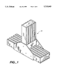
- FIG. 1 is a pictorial view of a space frame joining system in accordance with the present invention.
- FIG. 2 is an exploded view of the space frame joining system of FIG. 1.
- FIG. 3 is a partial top plan view of the space frame joining system of FIG. 2.
- FIG. 4 is an exploded view of a preferred embodiment of a space frame joining system in accordance with the present invention.
- FIG. 5 is a partial top plan view of the space frame joining system of FIG. 4.
- FIGS. 1-3 illustrate a typical space frame joining system 10 of the present invention.
- System 10 comprises a pair of lineal members 12 and 32 which are held together by a pair of universal joining members 50a and 50b.
- the lineal members 12 and 32 can be virtually any multi-sided shape but I prefer a four-sided rectangular shape.
- the first lineal member 12 has two interlocking sides where each side has a plurality of substantially similar longitudinal parallel grooves 14a and 14b, running the length of first lineal member 12.
- the second lineal member has a top surface 38 and a bottom surface 40.
- the first lineal member 12 is positioned substantially perpendicular to top surface 38 of the second lineal member 32 so that bottom end 20 sits flush against top surface 38.
- the first lineal member 12 can be positioned at various angles, such as 45°, relative to the top surface of the second lineal member 32.
- second lineal members which are identical in shape and size to the first lineal members described above. This allows a manufacturer to minimize inventory and to reduce costs of production.
- the second lineal member 32 includes a plurality of substantially similar longitudinal parallel grooves 34a running the length of top surface 38 and similar longitudinal grooves 34b running the length of bottom surface 40.
- the lineal members 12 and 32 can be any aluminum alloy such as the 5xxxx, 6xxx, or 7xxx series alloys or other light metals such as magnesium. I prefer to use aluminum alloys containing silicon and magnesium in proportions that make them heat treatable, particularly including aluminum alloys 6061, 6063, variations thereof and similar alloys.
- the lineal members of this invention generally are made of an extruded aluminum alloy. Extruded lineal members exhibit metallurgical and physical properties, such as alloy consistency, dimensional stability, ductility and strength, which are enhanced and more consistent than those typically obtained by other processes such as casting. I prefer to use extrude alloys over cast alloys primarily because of the lower cost. This invention does, however, comprehend lineal members either extruded or cast of any material.
- extruded refers to shaping by forcing through dies under pressure, to form longitudinally extending elements which may be cut into sections.
- extruding products an ingot or billet is forced into flow under pressure through a die opening to form an elongated shape.
- the lineal members of the present invention may be separated into segments such as by cutting or shearing.
- the rectangular lineal members 12 and 32 be substantially hollow.
- substantially hollow I mean that the majority of the cross section is hollow. This hollow configuration is primarily desirable to reduce the weight of the overall structure. There are of course practical limits on the lightweighting that can be accomplished. I have found, however, that the preferred thickness of wall 18 ranges from about 2.0 to 8.0 mm. A wall thickness of less than 2.0 mm renders it difficult to introduce grooves into the lineal members.
- the first lineal member 12 comprises longitudinally extending, substantially similar grooves 14a and 14b along interlocking sides 24a and 24b.
- each interlocking side has from 2 to 9 substantially parallel grooves which extend the length of lineal member 12.
- the grooves range from about 3.0 to 20 mm in width and from about 1.5 to 3.0 mm in depth.
- I can either employ an additional number of substantially equally positioned grooves or I can make the existing grooves wider to obtain structural integrity
- a lineal member having a 50 mm width I would employ three equally spaced parallel grooves, having groove widths of about 6 mm.
- first and second lineal members be standardized to facilitate efficient manufacture.
- second lineal member 32 comprises grooves 34a and 34b which are substantially identical in number, width, and depth as grooves 14a and 14b.
- grooves 14a, 14b, 34a, and 34b are included in the extrusion die profile which produces further efficiencies in the manufacturing process.
- Joining member 50a comprises span 52 and interlocking member 56 which is positioned perpendicularly to span 52.
- Interlocking member 56 comprises a plurality of substantially similar grooves 60 which extend generally across the width of interlocking member 56.
- Joining member 50a is mounted on lineal member 32 such that span 52 is flush against side 42a and grooves 60 interlock with grooves 14b of lineal member 12.
- joining member 50b comprises span 54 and interlocking member 58 which is mounted perpendicularly to span 50b.
- Interlocking member 58 comprises a plurality of substantially similar grooves 62 which extend generally across the width of interlocking member 58.
- Joining member 54 is mounted to lineal member 32 such that span 54 is flush against side 42b and grooves 62 interlock with grooves 14a of lineal member 12.
- the universal joining members of this invention generally are made of a light metal, preferably an extruded aluminum alloy.
- the extruded joining members have superior metallurgical an physical properties such as alloy consistency, dimensional stability, ductility and strength compared to those obtained by other processes such as casting.
- I may use a 7xxx series alloy instead of a 6xxx series alloy to obtain additional strength coupled with a somewhat thinner extrusion.
- Joining members 50a and 50b are attached to lineal members 12 and 32 by any suitable means such as welding, Preferably, I apply a uniform layer of an adhesive 65 to the surfaces 22a and 22b prior to joining. This allows the quality inspection of adhesive on the metal surface prior to the pieces being joined. In cases where access is limited, adhesive can be applied through adhesive injection holes 64a and 64b to attach the joining members to the lineal members.
- Suitable adhesives include modified epoxy or acrylic, most preferably I use a modified epoxy adhesive such as 3M® DP420 or DP460, Magnoliea 6250 Or 6384, and Hysol 9430 or an acrylic such as Lord 250, 256, f320 or V406.
- the gap between the mating surfaces of interlocking grooves 60 and 62 with lineal member grooves 14a and 14b ranges between 0.2 to 0.6 mm with 0.4 mm being the optimum. Larger tolerances can, however, be accepted. In these cases it is necessary to use a larger gap filling adhesive such as the acrylics mentioned above. Moreover, it may be necessary to increase the size of the joining members to increase the surface area for bonding. In this embodiment, the lower strength adhesive will produce an acceptable bond.
- I prepare the outside surfaces of the lineal members and joining members to increase the activation energy of these surfaces and thereby improving the bond between the bond and the metal. I can accomplish this in two ways. I can either chemically etch these surfaces or I can grit blast them. Although chemical etching is generally more effective, I prefer to grit blast because it is usually more economical.
- the primary function of the grooves is to improve the strength of the joint. Without the grooves, adhesives can be susceptible to catastrophic failure along shear paths, once a failure is initiated. The initiation is often induced by peel forces at the end of the bond line. The introduction of grooves staggers the bond line, making it less vulnerable to catastrophic failure. The interlocking of the lineal members and the joining members also improves the peel force resistance of the particular joint. While in service, the joints are flexed in various directions. Adhesives are most efficient when they are stressed in shear. The inclusion of the grooves increases the peel force resistance to resultant stresses out of the shear plane.
- the interlocking grooves provide the additional advantage of self-alignment. That is, the interlocking grooves hold the joint in place while the adhesive dries and bonds the members together. In contrast, parts to be welded must somehow be held precisely in place by fixtures or other extraneous means. This, of course, further complicates the manufacturing process and can potentially produce additional errors in tolerance.
- the interlocking grooves of the present invention eliminates this concern.
- adhesives with the present invention allows maximum design flexibility.
- the welds create heat affected zones in the members where the alloy's properties have been altered.
- designers must introduce a safety factor or an increased thickness of alloy to guarantee that the space frame will perform as desired.
- the use of adhesives does not create the inconsistencies that welds do and a the space frame can be designed to take advantage of the full T6 or maximum mechanical strengths properties for heat treatable alloys.
- the adhesive bond is stronger than either the lineal member or universal joining member.
- This combination of adhesive and heat treatable alloys allows the thinnest wall potential to be utilized and therefore provides the maximum in lightweighting possibilities.
- the grooves significantly increase the surface area of the adhesive and therefore reduces the surface area needed to exceed the extrusion material strength thereby increasing the strength of the joint.
- I can increase the surface area of the joining members that contact the lineal members. For example, I can increase the length of the spans so that they have more common area with the sides of the lineal members. In addition, I can increase the length and width of the interlocking member to increase the overlap between the interlocking members and the widths of the lineal members. Second, I can increase the thickness of the cross section of the universal joining member to increase its strength. And third, I can increase strength by selecting a different alloy.
- the lineal member I may upgrade from a 6063 to a 6061 to improve strength or for the joining members, I may switch from a 6xxx series alloy to a 7xxx series alloy for greater strength, depending upon the application.
- these variables can be optimized to produce the most desirable design.
- System 110 comprises a pair of lineal members 112 and 132 which are held together by two pair of universal joining members 150a and 150b.
- the first lineal member 112 has two interlocking sides where each side has a plurality of substantially similar longitudinal parallel grooves 114a and 114b, running the length of first lineal member 112.
- the second lineal member has a top surface 138 and a bottom surface 140.
- the first lineal member 112 is positioned substantially perpendicular to top surface 138 of the second lineal member 132 so that bottom end 120 sits flush against top surface 138.
- second lineal members which are identical in shape and size to the first lineal members described above.
- the second lineal member 132 includes a plurality of substantially similar longitudinal parallel grooves 134a running the length of the top surface 138 and similar longitudinal grooves 134b running the length of bottom surface 140.
- the pair of lineal members 112 and 132 are joined together by way of two pair of universal joining members 150a and 150b.
- Each of the four joining members 150a, b, c, and d comprise spans 152a, 152b, 154a and 154b and interlocking members 156a, 156b, 158a, and 158b.
- interlocking member 156a is mounted perpendicularly to span 150b; interlocking member 156b mounted perpendicularly to span 152a; interlocking member 158a positioned perpendicularly to span 154b; interlocking member 158b mounted perpendicularly to span 154a.
- each of the four joining members are extruded as a single shape.
- Each interlocking member comprises a plurality of substantially similar grooves 160, 161, 162 and 163 which extend generally across the width of each corresponding interlocking member 156b, 156a, 158a, and 158b.
- Joining members 150a and 150b are mounted to lineal member 132 such that spans 152a and 152b are flush against side 142a and grooves 160 interlock with grooves 114b of lineal member 112 and grooves 161 interlock with grooves 114a of lineal member 112.
- joining members 150c and 150d are mounted to lineal member 132 such that spans 154a and 154b are flush against side 142b and grooves 162 interlock with grooves 114b and grooves 163 interlock with grooves 114a.
- joining members 150a and 150b can be a single extruded member and likewise, joining members 150c and 150d can be a single extruded member. This simplifies the manufacturing process by reducing the number of parts and corresponding inventory. In general, however, adhesive should be applied through injection holes 164 after the lineal members and joining members have been interlocked.
- the lineal members and joining members can be any aluminum alloy or other light metal but I prefer that all members be constructed out of an extruded aluminum alloy such as 6061, 6063 or variations thereof.
Landscapes
- Engineering & Computer Science (AREA)
- Chemical & Material Sciences (AREA)
- Combustion & Propulsion (AREA)
- Transportation (AREA)
- Mechanical Engineering (AREA)
- Architecture (AREA)
- Structural Engineering (AREA)
- Body Structure For Vehicles (AREA)
- Standing Axle, Rod, Or Tube Structures Coupled By Welding, Adhesion, Or Deposition (AREA)
Abstract
Description
Claims (23)
Priority Applications (1)
| Application Number | Priority Date | Filing Date | Title |
|---|---|---|---|
| US08/663,591 US5715643A (en) | 1995-01-31 | 1996-06-14 | Automotive space frame joining system |
Applications Claiming Priority (2)
| Application Number | Priority Date | Filing Date | Title |
|---|---|---|---|
| US38139395A | 1995-01-31 | 1995-01-31 | |
| US08/663,591 US5715643A (en) | 1995-01-31 | 1996-06-14 | Automotive space frame joining system |
Related Parent Applications (1)
| Application Number | Title | Priority Date | Filing Date |
|---|---|---|---|
| US38139395A Continuation | 1995-01-31 | 1995-01-31 |
Publications (1)
| Publication Number | Publication Date |
|---|---|
| US5715643A true US5715643A (en) | 1998-02-10 |
Family
ID=23504863
Family Applications (1)
| Application Number | Title | Priority Date | Filing Date |
|---|---|---|---|
| US08/663,591 Expired - Lifetime US5715643A (en) | 1995-01-31 | 1996-06-14 | Automotive space frame joining system |
Country Status (1)
| Country | Link |
|---|---|
| US (1) | US5715643A (en) |
Cited By (29)
| Publication number | Priority date | Publication date | Assignee | Title |
|---|---|---|---|---|
| US6003898A (en) * | 1998-05-04 | 1999-12-21 | Aluminum Company Of America | Main beam-rear beam joint |
| US6094802A (en) * | 1994-07-25 | 2000-08-01 | Alusuisse Technology & Management Ltd. | Connecting element |
| US6123378A (en) * | 1998-05-04 | 2000-09-26 | Aluminum Company Of America | Cross beam-main beam integral joint |
| US6139094A (en) * | 1998-05-04 | 2000-10-31 | Aluminum Company Of America | Rocker to pillar joint |
| US6293617B1 (en) * | 1998-10-15 | 2001-09-25 | Honda Giken Kogyo Kabushiki Kaisha | Extruded material frame connection structure for vehicle |
| US6400047B1 (en) * | 1998-11-24 | 2002-06-04 | Festo Ag & Co. | Linear drive |
| US6561573B2 (en) * | 2000-07-21 | 2003-05-13 | Ferrari S.P.A. | Vehicle body |
| US6598360B1 (en) * | 2000-12-18 | 2003-07-29 | James M. Pratt | Basement water drainage conduit and methods of use thereof |
| US6619001B1 (en) * | 2002-01-02 | 2003-09-16 | James M. Pratt | Methods of use of a basement water drainage conduit |
| US6665935B2 (en) * | 2000-07-26 | 2003-12-23 | Daniel E. Panoz | Method of making a vehicle chassis of extruded links and couplers |
| US20050188640A1 (en) * | 2004-02-26 | 2005-09-01 | Miller Lester D. | Quick frame construction system and method |
| US6991400B1 (en) * | 2001-02-15 | 2006-01-31 | Negueloua Gerald I | Cap sealer for caulked joints |
| US7055918B2 (en) * | 2001-07-27 | 2006-06-06 | Lachance James L | Attachment element for joining a backplash to a countertop |
| EP1672227A1 (en) * | 2004-12-16 | 2006-06-21 | Snecma | Mechanical device comprising several pieces assembled in relatively precise positions |
| US20070051465A1 (en) * | 2005-02-28 | 2007-03-08 | Dow Global Technologies, Inc. | Method of attaching components and article formed using same |
| US20070108803A1 (en) * | 2005-11-16 | 2007-05-17 | Ford Global Technologies, Llc | Interlocked pillar and roof rail joint |
| US20080017770A1 (en) * | 2003-07-31 | 2008-01-24 | The Boeing Company | Utility Brackets for Securing Components to Structures |
| US20080164707A1 (en) * | 2007-01-08 | 2008-07-10 | Ford Global Technologies, Llc | Universal structural joint for automotive frames |
| US20090272055A1 (en) * | 2008-04-30 | 2009-11-05 | Griffiths Robert T | Wall panel system |
| US20100310308A1 (en) * | 2006-04-21 | 2010-12-09 | Richard Joseph Connell | Implement Frame Tube Joint with Weldable Connector |
| US20100322703A1 (en) * | 2009-06-19 | 2010-12-23 | David James Horwitz | Joint assembly with reinforcing member and foam |
| US20110061302A1 (en) * | 2008-03-10 | 2011-03-17 | Compagnie Plastic Omnium | Assembly consisting of an opening panel and reinforcing elements |
| US8641133B1 (en) | 2011-10-10 | 2014-02-04 | Robert Joseph Scaringe | High strength lightweight vehicle and an improved method for producing same |
| US20150007522A1 (en) * | 2013-07-02 | 2015-01-08 | Averve, Llc | Frame system |
| US9139235B2 (en) | 2013-05-21 | 2015-09-22 | Ford Global Technologies, Llc | Vehicle frame rail and pillar connection |
| WO2018138407A1 (en) * | 2017-01-25 | 2018-08-02 | Kulojaervi Tauno | Fastening element and arrangement in a frame structure of a vehicle |
| US10583629B2 (en) * | 2015-02-06 | 2020-03-10 | Kobe Steel, Ltd. | Joining structure |
| US10766543B2 (en) * | 2018-11-26 | 2020-09-08 | Korea Institute Of Industrial Technology | Joint member for coupling chassis frame and variable chassis module of vehicle using the same |
| WO2021036818A1 (en) * | 2019-08-30 | 2021-03-04 | 比亚迪股份有限公司 | Vehicle body framework connector and vehicle with same |
Citations (9)
| Publication number | Priority date | Publication date | Assignee | Title |
|---|---|---|---|---|
| FR990651A (en) * | 1944-03-23 | 1951-09-25 | Construction game | |
| US4069638A (en) * | 1974-06-05 | 1978-01-24 | Scanovator Ab | Structure of lightweight bars and connector means therefore |
| US4147007A (en) * | 1976-12-10 | 1979-04-03 | Ebco Industries, Ltd. | Matable modular elements for toy, display and model applications utilizing paired rib structure |
| US4618163A (en) * | 1983-12-24 | 1986-10-21 | Franz Hasler | Automotive chassis |
| US4660345A (en) * | 1984-10-10 | 1987-04-28 | Mr. Gasket Company | Vehicle space frame, castings therefor and method for remote construction |
| US4988230A (en) * | 1989-03-07 | 1991-01-29 | Aluminum Company Of America | Extruded node |
| US5059056A (en) * | 1989-03-07 | 1991-10-22 | Aluminum Company Of America | Extrdued node |
| GB2252056A (en) * | 1991-01-25 | 1992-07-29 | Chen Jeng Chwen | Toy construction panels |
| US5209541A (en) * | 1992-04-13 | 1993-05-11 | Ford Motor Company | Space frame joint construction |
-
1996
- 1996-06-14 US US08/663,591 patent/US5715643A/en not_active Expired - Lifetime
Patent Citations (9)
| Publication number | Priority date | Publication date | Assignee | Title |
|---|---|---|---|---|
| FR990651A (en) * | 1944-03-23 | 1951-09-25 | Construction game | |
| US4069638A (en) * | 1974-06-05 | 1978-01-24 | Scanovator Ab | Structure of lightweight bars and connector means therefore |
| US4147007A (en) * | 1976-12-10 | 1979-04-03 | Ebco Industries, Ltd. | Matable modular elements for toy, display and model applications utilizing paired rib structure |
| US4618163A (en) * | 1983-12-24 | 1986-10-21 | Franz Hasler | Automotive chassis |
| US4660345A (en) * | 1984-10-10 | 1987-04-28 | Mr. Gasket Company | Vehicle space frame, castings therefor and method for remote construction |
| US4988230A (en) * | 1989-03-07 | 1991-01-29 | Aluminum Company Of America | Extruded node |
| US5059056A (en) * | 1989-03-07 | 1991-10-22 | Aluminum Company Of America | Extrdued node |
| GB2252056A (en) * | 1991-01-25 | 1992-07-29 | Chen Jeng Chwen | Toy construction panels |
| US5209541A (en) * | 1992-04-13 | 1993-05-11 | Ford Motor Company | Space frame joint construction |
Cited By (46)
| Publication number | Priority date | Publication date | Assignee | Title |
|---|---|---|---|---|
| US6094802A (en) * | 1994-07-25 | 2000-08-01 | Alusuisse Technology & Management Ltd. | Connecting element |
| US6003898A (en) * | 1998-05-04 | 1999-12-21 | Aluminum Company Of America | Main beam-rear beam joint |
| US6123378A (en) * | 1998-05-04 | 2000-09-26 | Aluminum Company Of America | Cross beam-main beam integral joint |
| US6139094A (en) * | 1998-05-04 | 2000-10-31 | Aluminum Company Of America | Rocker to pillar joint |
| US6293617B1 (en) * | 1998-10-15 | 2001-09-25 | Honda Giken Kogyo Kabushiki Kaisha | Extruded material frame connection structure for vehicle |
| US6400047B1 (en) * | 1998-11-24 | 2002-06-04 | Festo Ag & Co. | Linear drive |
| US6561573B2 (en) * | 2000-07-21 | 2003-05-13 | Ferrari S.P.A. | Vehicle body |
| US6665935B2 (en) * | 2000-07-26 | 2003-12-23 | Daniel E. Panoz | Method of making a vehicle chassis of extruded links and couplers |
| US6598360B1 (en) * | 2000-12-18 | 2003-07-29 | James M. Pratt | Basement water drainage conduit and methods of use thereof |
| US6991400B1 (en) * | 2001-02-15 | 2006-01-31 | Negueloua Gerald I | Cap sealer for caulked joints |
| US7055918B2 (en) * | 2001-07-27 | 2006-06-06 | Lachance James L | Attachment element for joining a backplash to a countertop |
| US6619001B1 (en) * | 2002-01-02 | 2003-09-16 | James M. Pratt | Methods of use of a basement water drainage conduit |
| US20090283649A1 (en) * | 2003-07-31 | 2009-11-19 | Wood Jeffrey H | Utility Brackets for Securing Components to Structures |
| US20080017770A1 (en) * | 2003-07-31 | 2008-01-24 | The Boeing Company | Utility Brackets for Securing Components to Structures |
| US20050188640A1 (en) * | 2004-02-26 | 2005-09-01 | Miller Lester D. | Quick frame construction system and method |
| FR2879693A1 (en) * | 2004-12-16 | 2006-06-23 | Snecma Moteurs Sa | MECHANICAL DEVICE COMPRISING SEVERAL PIECES ASSEMBLED WITH PRECISE RELATIVE POSITIONING |
| US20060133894A1 (en) * | 2004-12-16 | 2006-06-22 | Snecma | Mechanical device comprising a plurality of parts assembled together with accurate relative positioning |
| US7530758B2 (en) | 2004-12-16 | 2009-05-12 | Snecma | Mechanical device comprising a plurality of parts assembled together with accurate relative positioning |
| EP1672227A1 (en) * | 2004-12-16 | 2006-06-21 | Snecma | Mechanical device comprising several pieces assembled in relatively precise positions |
| US20070051465A1 (en) * | 2005-02-28 | 2007-03-08 | Dow Global Technologies, Inc. | Method of attaching components and article formed using same |
| US7431378B2 (en) | 2005-11-16 | 2008-10-07 | Ford Global Technologies, Llc | Interlocked pillar and roof rail joint |
| US7293823B2 (en) * | 2005-11-16 | 2007-11-13 | Ford Global Technologies, Llc | Interlocked pillar and roof rail joint |
| US20080030050A1 (en) * | 2005-11-16 | 2008-02-07 | Ford Global Technologies, Llc | Interlocked pillar and roof rail joint |
| US20070108803A1 (en) * | 2005-11-16 | 2007-05-17 | Ford Global Technologies, Llc | Interlocked pillar and roof rail joint |
| US20100310308A1 (en) * | 2006-04-21 | 2010-12-09 | Richard Joseph Connell | Implement Frame Tube Joint with Weldable Connector |
| US9072213B2 (en) * | 2006-04-21 | 2015-07-07 | Deere & Company | Implement frame tube joint with weldable connector |
| US7488022B2 (en) | 2007-01-08 | 2009-02-10 | Ford Global Technologies, Llc | Universal structural joint for automotive frames |
| US20080164707A1 (en) * | 2007-01-08 | 2008-07-10 | Ford Global Technologies, Llc | Universal structural joint for automotive frames |
| US20110061302A1 (en) * | 2008-03-10 | 2011-03-17 | Compagnie Plastic Omnium | Assembly consisting of an opening panel and reinforcing elements |
| US8894128B2 (en) * | 2008-03-10 | 2014-11-25 | Compagnie Plastic Omnium | Assembly comprising of an opening panel and reinforcing elements |
| US20090272055A1 (en) * | 2008-04-30 | 2009-11-05 | Griffiths Robert T | Wall panel system |
| US20100322703A1 (en) * | 2009-06-19 | 2010-12-23 | David James Horwitz | Joint assembly with reinforcing member and foam |
| US8870488B2 (en) * | 2009-06-19 | 2014-10-28 | Duracase Proprietary Llc | Joint assembly with reinforcing member and foam |
| US8641133B1 (en) | 2011-10-10 | 2014-02-04 | Robert Joseph Scaringe | High strength lightweight vehicle and an improved method for producing same |
| US9139235B2 (en) | 2013-05-21 | 2015-09-22 | Ford Global Technologies, Llc | Vehicle frame rail and pillar connection |
| US20150007522A1 (en) * | 2013-07-02 | 2015-01-08 | Averve, Llc | Frame system |
| US9631364B2 (en) * | 2013-07-02 | 2017-04-25 | Averve, Llc | Wall panel framing system |
| US10583629B2 (en) * | 2015-02-06 | 2020-03-10 | Kobe Steel, Ltd. | Joining structure |
| WO2018138407A1 (en) * | 2017-01-25 | 2018-08-02 | Kulojaervi Tauno | Fastening element and arrangement in a frame structure of a vehicle |
| US10766543B2 (en) * | 2018-11-26 | 2020-09-08 | Korea Institute Of Industrial Technology | Joint member for coupling chassis frame and variable chassis module of vehicle using the same |
| WO2021036818A1 (en) * | 2019-08-30 | 2021-03-04 | 比亚迪股份有限公司 | Vehicle body framework connector and vehicle with same |
| CN112441142A (en) * | 2019-08-30 | 2021-03-05 | 比亚迪股份有限公司 | Vehicle body framework connects and has its vehicle |
| CN112441142B (en) * | 2019-08-30 | 2022-04-15 | 比亚迪股份有限公司 | Vehicle body framework connects and has its vehicle |
| US20220177046A1 (en) * | 2019-08-30 | 2022-06-09 | Byd Company Limited | Vehicle body framework connector and vehicle with same |
| EP3998186A4 (en) * | 2019-08-30 | 2022-07-27 | BYD Company Limited | VEHICLE BODY FRAME AND VEHICLE WITH IT |
| US12172703B2 (en) * | 2019-08-30 | 2024-12-24 | Byd Company Limited | Vehicle body framework connector and vehicle with same |
Similar Documents
| Publication | Publication Date | Title |
|---|---|---|
| US5715643A (en) | Automotive space frame joining system | |
| US5059056A (en) | Extrdued node | |
| KR100199537B1 (en) | Joint unit for hollow profiles | |
| US4722633A (en) | Compound joint and method for its production | |
| US6094802A (en) | Connecting element | |
| US5228259A (en) | Space frame connector | |
| US4986597A (en) | Vehicle space frame and a method for manufacturing of vehicle space frame parts | |
| GB2305639A (en) | Vehicle body frame structure | |
| EP1473213A2 (en) | Vehicle body construction | |
| CA2462516A1 (en) | Lightweight construction element and method for producing the same | |
| JPH0671364A (en) | Structural member and manufacturing method thereof | |
| CN107598405B (en) | Welded members, variable section box members and welding methods | |
| JP2784279B2 (en) | Structural structure using extruded light alloy | |
| JP2719543B2 (en) | Beam-column joint | |
| JP2580501Y2 (en) | Structural members for space frames of automobile bodies | |
| JP2021178330A (en) | Joining member manufacturing method, joining member, and framing structure | |
| JPS6322246Y2 (en) | ||
| KR100524638B1 (en) | Vehicle Body Frame Structure | |
| JP2719544B2 (en) | Beam-column joint | |
| JPH03250129A (en) | Manufacturing method of column/beam joint hardware | |
| JPH0623451A (en) | Hollow material and manufacturing method thereof | |
| JP4062274B2 (en) | Beam-column joint structure | |
| JP3325794B2 (en) | Column / beam joint hardware and column / beam joint structure | |
| JPH09164615A (en) | Honeycomb panel | |
| JPH1159413A (en) | Vehicular body of rolling stock |
Legal Events
| Date | Code | Title | Description |
|---|---|---|---|
| STCF | Information on status: patent grant |
Free format text: PATENTED CASE |
|
| FPAY | Fee payment |
Year of fee payment: 4 |
|
| FPAY | Fee payment |
Year of fee payment: 8 |
|
| AS | Assignment |
Owner name: KAISER ALUMINUM FABRICATED PRODUCTS, LLC, CALIFORN Free format text: ASSIGNMENT OF ASSIGNORS INTEREST;ASSIGNOR:KAISE ALUMINUM & CHEMICAL CORP.;REEL/FRAME:017931/0270 Effective date: 20060706 |
|
| AS | Assignment |
Owner name: KAISER ALUMINUM FABRICATED PRODUCTS, LLC, CALIFORN Free format text: SECURITY AGREEMENT;ASSIGNOR:JPMORGAN CHASE BANK, N.A.;REEL/FRAME:018505/0609 Effective date: 20060706 Owner name: KAISER ALUMINUM FABRICATED PRODUCTS, LLC, CALIFORN Free format text: SECURITY AGREEMENT;ASSIGNORS:JPMORGAN CHASE BANK, N.A.;WILMINGTON TRUST COMPANY;REEL/FRAME:018505/0636 Effective date: 20060706 |
|
| AS | Assignment |
Owner name: JPMORGAN CHASE BANK, N.A., WISCONSIN Free format text: CORRECTIVE ASSIGNMENT TO CORRECT THE CONVEYING PARTY. IT SHOULD BE KAISER ALUMINUM FABRICATED PRODUCTS, LLC PREVIOUSLY RECORDED ON REEL 018505 FRAME 0609;ASSIGNOR:KAISER ALUMINUM FABRICATED PRODUCTS, LLC;REEL/FRAME:018515/0422 Effective date: 20060706 Owner name: JPMORGAN CHASE BANK, N.A., WISCONSIN Free format text: CORRECTIVE ASSIGNMENT TO CORRECT THE CONVEYING PARTY. IT SHOULD BE KAISER ALUMINUM FABRICATED PRODUCTS, LLC PREVIOUSLY RECORDED ON REEL 018505 FRAME 0636;ASSIGNOR:KAISER ALUMINUM FABRICATED PRODUCTS, LLC;REEL/FRAME:018515/0438 Effective date: 20060706 Owner name: WILMINGTON TRUST COMPANY, DELAWARE Free format text: CORRECTIVE ASSIGNMENT TO CORRECT THE CONVEYING PARTY. IT SHOULD BE KAISER ALUMINUM FABRICATED PRODUCTS, LLC PREVIOUSLY RECORDED ON REEL 018505 FRAME 0636;ASSIGNOR:KAISER ALUMINUM FABRICATED PRODUCTS, LLC;REEL/FRAME:018515/0438 Effective date: 20060706 |
|
| AS | Assignment |
Owner name: KAISER ALUMINUM FABRICATED PRODUCTS, LLC, CALIFORN Free format text: RELEASE BY SECURED PARTY;ASSIGNOR:WILMINGTON TRUST COMPANY;REEL/FRAME:021172/0180 Effective date: 20080610 |
|
| FPAY | Fee payment |
Year of fee payment: 12 |
|
| AS | Assignment |
Owner name: JPMORGAN CHASE BANK, N.A.,TEXAS Free format text: SECURITY AGREEMENT;ASSIGNOR:KAISER ALUMINUM FABRICATED PRODUCTS, LLC;REEL/FRAME:024120/0833 Effective date: 20100322 |
|
| AS | Assignment |
Owner name: JP MORGAN CHASE BANK, N.A., AS ADMINISTATIVE AGENT Free format text: CORRECTIVE ASSIGNMENT TO CORRECT THE NAME OF THE RECEIVING PARTY, PREVIOUSLY RECORDED ON REEL 024120 FRAME 0833;ASSIGNOR:KAISER ALUMINUM FABRICATED PRODUCTS, LLC;REEL/FRAME:024151/0092 Effective date: 20100322 |
|
| AS | Assignment |
Owner name: WELLS FARGO BANK, NATIONAL ASSOCIATION, CALIFORNIA Free format text: SECURITY INTEREST;ASSIGNOR:KAISER ALUMINUM FABRICATED PRODUCTS, LLC;REEL/FRAME:050885/0952 Effective date: 20191030 Owner name: KAISER ALUMINUM FABRICATED PRODUCTS, LLC, CALIFORN Free format text: RELEASE BY SECURED PARTY;ASSIGNOR:JPMORGAN CHASE BANK, N.A., AS ADMINISTRATIVE AGENT;REEL/FRAME:050885/0935 Effective date: 20191031 Owner name: KAISER ALUMINUM FABRICATED PRODUCTS, LLC, CALIFORN Free format text: RELEASE BY SECURED PARTY;ASSIGNOR:JPMORGAN CHASE BANK, N.A., AS ADMINISTRATIVE AGENT;REEL/FRAME:050885/0940 Effective date: 20191030 |