US5705737A - Pressure leakage detector - Google Patents
Pressure leakage detector Download PDFInfo
- Publication number
- US5705737A US5705737A US08/805,904 US80590497A US5705737A US 5705737 A US5705737 A US 5705737A US 80590497 A US80590497 A US 80590497A US 5705737 A US5705737 A US 5705737A
- Authority
- US
- United States
- Prior art keywords
- pressure
- leakage
- primary
- valve
- gage
- Prior art date
- Legal status (The legal status is an assumption and is not a legal conclusion. Google has not performed a legal analysis and makes no representation as to the accuracy of the status listed.)
- Expired - Fee Related
Links
- 238000001514 detection method Methods 0.000 abstract description 11
- 238000011179 visual inspection Methods 0.000 abstract description 5
- 230000001105 regulatory effect Effects 0.000 abstract 1
- 239000002826 coolant Substances 0.000 description 8
- 238000001816 cooling Methods 0.000 description 8
- 239000002828 fuel tank Substances 0.000 description 4
- 239000000945 filler Substances 0.000 description 2
- 239000000446 fuel Substances 0.000 description 2
- 238000012544 monitoring process Methods 0.000 description 2
- 230000002093 peripheral effect Effects 0.000 description 2
- 238000004891 communication Methods 0.000 description 1
- 239000012530 fluid Substances 0.000 description 1
- 238000012986 modification Methods 0.000 description 1
- 230000004048 modification Effects 0.000 description 1
- 230000008016 vaporization Effects 0.000 description 1
- 238000009834 vaporization Methods 0.000 description 1
Images


Classifications
-
- G—PHYSICS
- G01—MEASURING; TESTING
- G01M—TESTING STATIC OR DYNAMIC BALANCE OF MACHINES OR STRUCTURES; TESTING OF STRUCTURES OR APPARATUS, NOT OTHERWISE PROVIDED FOR
- G01M3/00—Investigating fluid-tightness of structures
- G01M3/02—Investigating fluid-tightness of structures by using fluid or vacuum
- G01M3/025—Details with respect to the testing of engines or engine parts
Definitions
- the present invention relates to a leakage detector and in particular to a leakage detector using pressure drop to detect leakage.
- FIG. 1 of the attached drawings A conventional device to preform such a leakage detection is shown in FIG. 1 of the attached drawings, comprising a manually operated air pump A having a pressures gage A1 mounted thereon.
- the air pump A has an outlet tube with an adaptor A2 fixed thereon to connect to a filler opening of an automobile radiator T.
- the principal object of the present invention is to provide a pressure leakage detector which overcomes the drawbacks of the prior art pressure leakage detecting device.
- Another object of the present invention is to provide a pressure leakage detector which supplies pressurized air from a source to a closed system on which the leakage detection is to be preformed and then cut off the pressure supply so that by monitoring the internal pressure change of the closed system, any leakage on the closed system may be detected.
- Another object of the present invention is to provide a pressure leakage detector which continuously supplies pressurized air from a source to a large sealed container so that any leakage on the large container may be detected by visual inspection.
- a pressure leakage detector comprising a primary four way connector having a first, second, third and fourth ports and a second primary four way connector having a first, second, third and fourth ports.
- a first pressure gage is mounted to the first port of the primary connector and a second pressure gage is mounted to the first port of the secondary connector.
- a valve is connected between the second ports of the primary and secondary connectors to provide a controllable fluid communication therebetween.
- a pressure regulator is connected to the third port of the primary connector and having an inlet port adapted to connect to a pressurized air source, such as an air compressor.
- a manually operated pressure relief valve is mounted to the third port.
- a valve for directly providing the pressurized air to an object to be detected is provided on the fourth port of the primary connector.
- a valve for providing the pressurized air from the secondary connector so an object to be detected is provided on the fourth port of the secondary connector.
- FIG. 1 is a perspective view showing a conventional leakage detector
- FIG. 2 is a perspective view showing a pressure leakage detector constructed in accordance with a preferred embodiment of the present invention
- FIGS. 3A-3F is shows an example of the operation of the pressure leakage detector of the present invention.
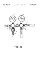
- FIG. 4 shows the application of the leakage detector of the present invention in detecting the leakage of a large sealed container
- the pressure leakage detector of the present invention is particularly suitable in detecting the leakages occurring on closed systems of an automobile, such as fuel supply system, engine cooling system, oil reservoir.
- the pressure leakage detector of the present invention comprises a primary pressure gage 10 which is connected to a pressure source, such as an air compressor P, and a secondary pressure gage 20 which is connected to the primary pressure gage 10 by means of a valve 30.
- the secondary pressure gage 20 is adapted to connect to a closed system or a sealed container On which leakage detection is to be performed.
- Both the primary and secondary pressure gages 10 and 20 are provided with a four way connector 11 or 21 each having four ports of which a first port is connected to the primary and secondary pressure gages 10 and 20 and a second port is connected to each other by the valve 30.
- a third port of the primary four way connector 11 has a pressure regulator 13 mounted thereon with an inlet port 14 of the pressure regulator 13 connected to the air compressor P by means of suitable piping or tube.
- the pressure regulator 13 provides a manual control to the pressure flowing into the primary pressure gage 10.
- a fourth port of the primary four way connector 11 is provided with a valve 12 for directly and continuously supplying pressurized air to a system or container to be detected.
- a third port of the secondary four way connector 21 is also provided with a valve 23 for the purpose of manually operated pressure relief.
- a fourth port of the secondary four way connector 23 is connected a hose 221 via a valve 22.
- An adaptor 222 is provided on the remote end of the hose 221 adapted to connect to for example a piping T4 of the secondary coolant reservoir cap T2 which is in turn connected to the radiator T1 via a hose T3, as shown in FIG. 3A.
- a leakage detection may be performed on the engine cooling system and the operation of the leakage detection on the engine cooling system will be described as an example of the application of the present invention.
- the present invention may also be used in detecting the leakage of other closed system, such as fuel supply system.
- the operator connects the adaptor 222 to the piping T4 of the second coolant reservoir cap T2 and connecting the inlet port 14 of the pressure regulator 13 to an air compressor P.
- the valve 30 between the primary and secondary gages 10 and 20 is initially closed. Starting the compressor P and adjusting the pressure regulator 13, the pressure inside the primary pressure gage 10 is increased to a desired level set by the pressure regulator 13, see FIG. 3B, with the reading of the primary pressure gage 10 indicating the pressure.
- the pressure is allowed to enter the secondary pressure gage 20 and is limited within the secondary pressure gage 20, until the reading of the primary pressure gage 10 is substantially the same as that of the secondary pressure gage 20.
- the valve 23 for manual pressure relief is always closed unless a pressure relief operation is to be carried out. Also in this case, the fourth port of the primary four way connector 11 is closed.
- valve 22 the pressurized air is conducted into the engine cooling system via the adaptor 222, see FIG. 3D.
- the reading of the secondary gage 20 will temporally change but soon return to its original position which is substantially the same as the reading of the primary pressure gage 10.
- the valve 30 is closed to cut off the pressurized air supplied via the primary four way connector 11, see FIG. 3E, and monitor the reading of the secondary pressure gage 20.
- a drop of the reading of the secondary pressure gage 20 indicates a leakage on the system that is detected and then a visual inspection with/without bubble detection method may be conducted to determine the exact location of leakage.
- the operator may relieve the pressure inside the engine cooling system by opening the valve 23, as shown in FIG. 3F.
- the pressure leakage detector of the present invention may also have other applications, for example to detect the leakage of a fuel tank, as shown in FIG. 4.
- the pressurized air from the air compressor (not shown in FIG. 4) via the primary four way connector 11 is directly supplied to the fuel tank T via the fourth port of the primary four way connector 11 by opening the valve 12.
- the valve 30 between the primary and secondary pressure gages 10 and 20 is closed.
- the pressure supplied to the fuel tank T is set to a desired level by means of the pressure regulator 13.
- the pressurized air is continuously supplied to the fuel tank T and a visual inspection with/without bubble detection method may then be carried out to determined the exact location of leakage. This way is particularly suitable for detecting leakage on large containers.
Landscapes
- Physics & Mathematics (AREA)
- General Physics & Mathematics (AREA)
- Examining Or Testing Airtightness (AREA)
- Measuring Fluid Pressure (AREA)
Abstract
A pressure leakage detector includes a primary gage and a secondary gage selectively connected to each other by means of a valve. The primary gage is connected to an air compressor via a pressure regulator for regulating the pressure supplied thereto and has an outlet port adapted to directly continuously supply the pressure to a large container to detect the leakage of container by means of visual inspection. The secondary gage has an outlet port adapted to connect to a closed system on which a leakage detection is to be carried out. By opening the valve between the two gages to have the closed system reaches a predetermined internal pressured set by the regulator and then closing the valve, a leakage of the closed system may be found by a drop of the pressure reading of the secondary gage. Thereafter, a visual inspection will indicate the exact location of leakage. Thus a precise and correct detection on either a small volume closed system or a large container may be preformed in an quite easy manner.
Description
The present invention relates to a leakage detector and in particular to a leakage detector using pressure drop to detect leakage.
In an automobile, there are several sealed or closed systems, such as engine cooling system, including the radiator, which in a normal operation should be sealingly closed so as to maintain the internal pressure to prevent the coolant flowing through the system from being vaporized. Any serious leakage in the system will result in vaporization of the coolant which in turn reduces the amount of heat that the coolant can carry away from the engine, causing significant temperature rise in the engine and eventually damaging the engine. One of the ways to detect the leakage of the engine cooling system is to pressurize the coolant inside the system by pressurized air to a predetermined level and monitor the internal pressure of the system. If a pressure drop occurs, then there is a leakage on the system.
A conventional device to preform such a leakage detection is shown in FIG. 1 of the attached drawings, comprising a manually operated air pump A having a pressures gage A1 mounted thereon. The air pump A has an outlet tube with an adaptor A2 fixed thereon to connect to a filler opening of an automobile radiator T. By manually operating the air pump A to pump air into the radiator T and pressurize the coolant inside the radiator T to a predetermined level which is read by the pressure gage A1, one may know if there is any leakage on the radiator T by monitoring the reading of the pressure gage A1. If a significant pressure drop is known from the gage A1, then there is leakage on the radiator T.
This conventional way although effective in determining if there is leakage of the radiator T itself, yet is not capable to detect any leakage occurring on peripheral parts of the radiator T, such as the filler cap T1 of the radiator T and the secondary coolant reservoir, including the cap T2, piping T4 and hose T3 connecting to the radiator T. Any leakage on these peripheral parts similarly causes serious damage to the engine.
It is therefore desirable to provide a pressure leakage detector which allows a user to conduct a more complete detection of the leakage of any sealingly closed system or container by suitably pressurizing the system.
Therefore, the principal object of the present invention is to provide a pressure leakage detector which overcomes the drawbacks of the prior art pressure leakage detecting device.
Another object of the present invention is to provide a pressure leakage detector which supplies pressurized air from a source to a closed system on which the leakage detection is to be preformed and then cut off the pressure supply so that by monitoring the internal pressure change of the closed system, any leakage on the closed system may be detected.
Another object of the present invention is to provide a pressure leakage detector which continuously supplies pressurized air from a source to a large sealed container so that any leakage on the large container may be detected by visual inspection.
In accordance with the present invention, there is provided a pressure leakage detector comprising a primary four way connector having a first, second, third and fourth ports and a second primary four way connector having a first, second, third and fourth ports. A first pressure gage is mounted to the first port of the primary connector and a second pressure gage is mounted to the first port of the secondary connector. A valve is connected between the second ports of the primary and secondary connectors to provide a controllable fluid communication therebetween. A pressure regulator is connected to the third port of the primary connector and having an inlet port adapted to connect to a pressurized air source, such as an air compressor. A manually operated pressure relief valve is mounted to the third port. A valve for directly providing the pressurized air to an object to be detected is provided on the fourth port of the primary connector. A valve for providing the pressurized air from the secondary connector so an object to be detected is provided on the fourth port of the secondary connector.
The present invention will be better understood from the following description of a preferred embodiment thereof with reference to the attached drawings, wherein:
FIG. 1 is a perspective view showing a conventional leakage detector;
FIG. 2 is a perspective view showing a pressure leakage detector constructed in accordance with a preferred embodiment of the present invention;
FIGS. 3A-3F is shows an example of the operation of the pressure leakage detector of the present invention;
FIG. 4 shows the application of the leakage detector of the present invention in detecting the leakage of a large sealed container
With reference to the drawings and in particular to FIG. 2, wherein a pressure leakage detector constructed in accordance with a preferred embodiment of the present invention is shown, the pressure leakage detector of the present invention is particularly suitable in detecting the leakages occurring on closed systems of an automobile, such as fuel supply system, engine cooling system, oil reservoir. As shown in FIG. 2, the pressure leakage detector of the present invention comprises a primary pressure gage 10 which is connected to a pressure source, such as an air compressor P, and a secondary pressure gage 20 which is connected to the primary pressure gage 10 by means of a valve 30. The secondary pressure gage 20 is adapted to connect to a closed system or a sealed container On which leakage detection is to be performed.
Both the primary and secondary pressure gages 10 and 20 are provided with a four way connector 11 or 21 each having four ports of which a first port is connected to the primary and secondary pressure gages 10 and 20 and a second port is connected to each other by the valve 30. A third port of the primary four way connector 11 has a pressure regulator 13 mounted thereon with an inlet port 14 of the pressure regulator 13 connected to the air compressor P by means of suitable piping or tube. The pressure regulator 13 provides a manual control to the pressure flowing into the primary pressure gage 10. A fourth port of the primary four way connector 11 is provided with a valve 12 for directly and continuously supplying pressurized air to a system or container to be detected.
A third port of the secondary four way connector 21 is also provided with a valve 23 for the purpose of manually operated pressure relief. A fourth port of the secondary four way connector 23 is connected a hose 221 via a valve 22. An adaptor 222 is provided on the remote end of the hose 221 adapted to connect to for example a piping T4 of the secondary coolant reservoir cap T2 which is in turn connected to the radiator T1 via a hose T3, as shown in FIG. 3A.
With such an arrangement shown in FIG. 3A, a leakage detection may be performed on the engine cooling system and the operation of the leakage detection on the engine cooling system will be described as an example of the application of the present invention. However, it should be understood that the present invention may also be used in detecting the leakage of other closed system, such as fuel supply system.
With reference to FIG. 3A first, as described above, in using the leakage detector of the present invention to detect the leakage of the engine cooling system, the operator connects the adaptor 222 to the piping T4 of the second coolant reservoir cap T2 and connecting the inlet port 14 of the pressure regulator 13 to an air compressor P. The valve 30 between the primary and secondary gages 10 and 20 is initially closed. Starting the compressor P and adjusting the pressure regulator 13, the pressure inside the primary pressure gage 10 is increased to a desired level set by the pressure regulator 13, see FIG. 3B, with the reading of the primary pressure gage 10 indicating the pressure. By closing the valve 22 and opening the valve 30, as shown in FIG. 3C, the pressure is allowed to enter the secondary pressure gage 20 and is limited within the secondary pressure gage 20, until the reading of the primary pressure gage 10 is substantially the same as that of the secondary pressure gage 20. It should be noted that the valve 23 for manual pressure relief is always closed unless a pressure relief operation is to be carried out. Also in this case, the fourth port of the primary four way connector 11 is closed.
Now, by opening valve 22, the pressurized air is conducted into the engine cooling system via the adaptor 222, see FIG. 3D. By doing so, the reading of the secondary gage 20 will temporally change but soon return to its original position which is substantially the same as the reading of the primary pressure gage 10. Once the reading of the secondary pressure gage 20 restores its original level, the valve 30 is closed to cut off the pressurized air supplied via the primary four way connector 11, see FIG. 3E, and monitor the reading of the secondary pressure gage 20. A drop of the reading of the secondary pressure gage 20 indicates a leakage on the system that is detected and then a visual inspection with/without bubble detection method may be conducted to determine the exact location of leakage.
No pressure drop indicates that the system has no leakage.
Once the detection is completed, the operator may relieve the pressure inside the engine cooling system by opening the valve 23, as shown in FIG. 3F.
As mentioned above, the pressure leakage detector of the present invention may also have other applications, for example to detect the leakage of a fuel tank, as shown in FIG. 4. In such an application, the pressurized air from the air compressor (not shown in FIG. 4) via the primary four way connector 11 is directly supplied to the fuel tank T via the fourth port of the primary four way connector 11 by opening the valve 12. The valve 30 between the primary and secondary pressure gages 10 and 20 is closed. The pressure supplied to the fuel tank T is set to a desired level by means of the pressure regulator 13. In this situation, the pressurized air is continuously supplied to the fuel tank T and a visual inspection with/without bubble detection method may then be carried out to determined the exact location of leakage. This way is particularly suitable for detecting leakage on large containers.
It is apparent that although the present invention is illustrated with the description of the preferred embodiment, it is contemplated that there may be changes and modifications in the described embodiment that can be carried out without departing from the scope of the invention which is intended to be limited only by the appended claims.
Claims (2)
1. A pressure leakage detector comprising a primary four way connector having a first, second, third and fourth ports and a second primary four way connector having a first, second, third and fourth ports, a primary pressure gage being mounted to the first port of the primary four way connector and a secondary pressure gage being mounted to the first port of the secondary four way connector, a valve being connected between the second ports of the primary and secondary four way connectors; a pressure regulator being connected to the third port of the primary four way connector and having an inlet port adapted to connect to a pressurized air source, a manually operated pressure relief valve being mounted to the third port of the secondary four way connector, a valve for directly providing the pressurized air to an object to be detected being provided on the fourth port of the primary four way connector, a valve for providing the pressurized air from the secondary four way connector to an object to be detected being provided on the fourth port of the secondary four way connector.
2. The pressure leakage detector as claimed in claim 1, wherein the pressurized air source comprises an air compressor.
Priority Applications (2)
| Application Number | Priority Date | Filing Date | Title |
|---|---|---|---|
| US08/805,904 US5705737A (en) | 1997-03-04 | 1997-03-04 | Pressure leakage detector |
| DE29705190U DE29705190U1 (en) | 1997-03-04 | 1997-03-21 | Pressure loss detector |
Applications Claiming Priority (2)
| Application Number | Priority Date | Filing Date | Title |
|---|---|---|---|
| US08/805,904 US5705737A (en) | 1997-03-04 | 1997-03-04 | Pressure leakage detector |
| DE29705190U DE29705190U1 (en) | 1997-03-04 | 1997-03-21 | Pressure loss detector |
Publications (1)
| Publication Number | Publication Date |
|---|---|
| US5705737A true US5705737A (en) | 1998-01-06 |
Family
ID=26060105
Family Applications (1)
| Application Number | Title | Priority Date | Filing Date |
|---|---|---|---|
| US08/805,904 Expired - Fee Related US5705737A (en) | 1997-03-04 | 1997-03-04 | Pressure leakage detector |
Country Status (2)
| Country | Link |
|---|---|
| US (1) | US5705737A (en) |
| DE (1) | DE29705190U1 (en) |
Cited By (24)
| Publication number | Priority date | Publication date | Assignee | Title |
|---|---|---|---|---|
| US6318155B1 (en) * | 1997-07-25 | 2001-11-20 | Bruce Carr | Pressure testing apparatus |
| US6408682B2 (en) | 2000-02-07 | 2002-06-25 | Steris Inc. | Leak detection method for endoscopes |
| US6412334B1 (en) * | 2000-02-07 | 2002-07-02 | Steris Inc. | Leak detector for endoscopes |
| US6499299B2 (en) * | 2001-04-13 | 2002-12-31 | Ronald Propernick | Apparatus and method for diagnosing pressure-related problems in turbocharged engines |
| US6530261B1 (en) * | 2001-01-16 | 2003-03-11 | James F. Foster | Semi-truck trailer brake test device, system and method |
| US6651486B1 (en) | 2000-09-29 | 2003-11-25 | Basic Resources, Inc. | Standup pressure testing device and method |
| US20040238027A1 (en) * | 2002-09-06 | 2004-12-02 | Johnson Danny A. | Gas meter valve and method |
| US20060032647A1 (en) * | 2004-06-14 | 2006-02-16 | Petty Eric M | Quick strike pneumatic pressure regulator |
| FR2883968A1 (en) * | 2005-04-01 | 2006-10-06 | Facom Sa | Motor vehicle e.g. man-riding car, engine`s cooling system sealing test device, has supply units supplying air to measuring tank having outlet communicating with duct, and manometer, coupling and inserts placed on respective walls of shell |
| US20060252991A1 (en) * | 2005-05-06 | 2006-11-09 | Melissa Kubach | Systems and methods for endoscope integrity testing |
| US20060252990A1 (en) * | 2005-05-06 | 2006-11-09 | Melissa Kubach | Systems and methods for endoscope integrity testing |
| US20060260747A1 (en) * | 2000-05-30 | 2006-11-23 | Jun Hirose | Gas introduction system for temperature adjustment of object to be processed |
| US20070060791A1 (en) * | 2005-05-06 | 2007-03-15 | Melissa Kubach | Computer systems and software for operating an endoscope integrity tester |
| US20070238923A1 (en) * | 2005-05-06 | 2007-10-11 | Melissa Kubach | Endoscope Integrity Tester Including Context-Sensitive Compensation and Methods of Context-Sensitive Integrity Testing |
| US20080090444A1 (en) * | 2006-10-13 | 2008-04-17 | Luzbetak Mark A | Connector for use in single and double breast pumping |
| US20080216560A1 (en) * | 2007-03-09 | 2008-09-11 | Ridgway Mark W | Leak detecting apparatus |
| US7454956B1 (en) * | 2005-09-22 | 2008-11-25 | Lopresti William J | Heat exchanger leak detection using mass gas flow metering |
| US7614283B2 (en) | 2006-04-17 | 2009-11-10 | Lincoln Industrial Corporation | Cooling system testing apparatus and methods |
| US20090301174A1 (en) * | 2008-06-10 | 2009-12-10 | Deming Wen | Cooling system pressure tester |
| US20120085180A1 (en) * | 2010-10-08 | 2012-04-12 | Endress + Hauser Gmbh + Co. Kg | Measurement arrangement |
| US20130145825A1 (en) * | 2011-12-07 | 2013-06-13 | Andreas Stihl Ag & Co. Kg | Method for leak-testing and device for carrying out the method |
| US20160231195A1 (en) * | 2013-09-17 | 2016-08-11 | Korea Fuel-Tech Corporation | Device for inspecting canister for vehicle |
| CN109519394A (en) * | 2017-09-20 | 2019-03-26 | 格兰富控股联合股份公司 | Pump seal leak detection system |
| US11035749B2 (en) * | 2019-02-07 | 2021-06-15 | Georg Fischer, LLC | Leak test system and method for thermoplastic piping |
Citations (4)
| Publication number | Priority date | Publication date | Assignee | Title |
|---|---|---|---|---|
| US3577768A (en) * | 1969-09-02 | 1971-05-04 | A & L Battery & Electric Servi | Hydrostatic testing apparatus |
| US3975944A (en) * | 1975-06-23 | 1976-08-24 | Allied Automotive, Inc. | Hydrostatic testing and recording apparatus |
| US4350038A (en) * | 1980-05-19 | 1982-09-21 | The Stellhorn Company | Fluidic type leak testing machine |
| US4993256A (en) * | 1988-04-20 | 1991-02-19 | Kabushiki Kaisha Fukuda | Leakage test method and apparatus |
-
1997
- 1997-03-04 US US08/805,904 patent/US5705737A/en not_active Expired - Fee Related
- 1997-03-21 DE DE29705190U patent/DE29705190U1/en not_active Expired - Lifetime
Patent Citations (4)
| Publication number | Priority date | Publication date | Assignee | Title |
|---|---|---|---|---|
| US3577768A (en) * | 1969-09-02 | 1971-05-04 | A & L Battery & Electric Servi | Hydrostatic testing apparatus |
| US3975944A (en) * | 1975-06-23 | 1976-08-24 | Allied Automotive, Inc. | Hydrostatic testing and recording apparatus |
| US4350038A (en) * | 1980-05-19 | 1982-09-21 | The Stellhorn Company | Fluidic type leak testing machine |
| US4993256A (en) * | 1988-04-20 | 1991-02-19 | Kabushiki Kaisha Fukuda | Leakage test method and apparatus |
Cited By (37)
| Publication number | Priority date | Publication date | Assignee | Title |
|---|---|---|---|---|
| US6318155B1 (en) * | 1997-07-25 | 2001-11-20 | Bruce Carr | Pressure testing apparatus |
| US6408682B2 (en) | 2000-02-07 | 2002-06-25 | Steris Inc. | Leak detection method for endoscopes |
| US6412334B1 (en) * | 2000-02-07 | 2002-07-02 | Steris Inc. | Leak detector for endoscopes |
| US20060260747A1 (en) * | 2000-05-30 | 2006-11-23 | Jun Hirose | Gas introduction system for temperature adjustment of object to be processed |
| US6651486B1 (en) | 2000-09-29 | 2003-11-25 | Basic Resources, Inc. | Standup pressure testing device and method |
| US6530261B1 (en) * | 2001-01-16 | 2003-03-11 | James F. Foster | Semi-truck trailer brake test device, system and method |
| US6499299B2 (en) * | 2001-04-13 | 2002-12-31 | Ronald Propernick | Apparatus and method for diagnosing pressure-related problems in turbocharged engines |
| US20040238027A1 (en) * | 2002-09-06 | 2004-12-02 | Johnson Danny A. | Gas meter valve and method |
| US20060032647A1 (en) * | 2004-06-14 | 2006-02-16 | Petty Eric M | Quick strike pneumatic pressure regulator |
| FR2883968A1 (en) * | 2005-04-01 | 2006-10-06 | Facom Sa | Motor vehicle e.g. man-riding car, engine`s cooling system sealing test device, has supply units supplying air to measuring tank having outlet communicating with duct, and manometer, coupling and inserts placed on respective walls of shell |
| US20060252990A1 (en) * | 2005-05-06 | 2006-11-09 | Melissa Kubach | Systems and methods for endoscope integrity testing |
| US20060252991A1 (en) * | 2005-05-06 | 2006-11-09 | Melissa Kubach | Systems and methods for endoscope integrity testing |
| US20070060791A1 (en) * | 2005-05-06 | 2007-03-15 | Melissa Kubach | Computer systems and software for operating an endoscope integrity tester |
| US20070149848A1 (en) * | 2005-05-06 | 2007-06-28 | Melissa Kubach | Computer Software for an Endoscope Leak Tester |
| US20070161859A1 (en) * | 2005-05-06 | 2007-07-12 | Melissa Kubach | Computer Control and Record System for an Endoscope Leak Tester |
| US20070238923A1 (en) * | 2005-05-06 | 2007-10-11 | Melissa Kubach | Endoscope Integrity Tester Including Context-Sensitive Compensation and Methods of Context-Sensitive Integrity Testing |
| US9277850B2 (en) | 2005-05-06 | 2016-03-08 | Medivators Inc. | Endoscope integrity tester including context-sensitive compensation and methods of context-sensitive integrity testing |
| US8109871B2 (en) | 2005-05-06 | 2012-02-07 | Minntech Corporation | Endoscope integrity tester including context-sensitive compensation and methods of context-sensitive integrity testing |
| US7454956B1 (en) * | 2005-09-22 | 2008-11-25 | Lopresti William J | Heat exchanger leak detection using mass gas flow metering |
| US7614283B2 (en) | 2006-04-17 | 2009-11-10 | Lincoln Industrial Corporation | Cooling system testing apparatus and methods |
| US7824361B2 (en) * | 2006-10-13 | 2010-11-02 | Medela Holding Ag | Connector for use in single and double breast pumping |
| US20110087162A1 (en) * | 2006-10-13 | 2011-04-14 | Medela Ag | Connector for Use in Single and Double Breast Pumping |
| US20080090444A1 (en) * | 2006-10-13 | 2008-04-17 | Luzbetak Mark A | Connector for use in single and double breast pumping |
| US8273057B2 (en) | 2006-10-13 | 2012-09-25 | Medela Holding Ag | Connector for use in single and double breast pumping |
| US7841229B2 (en) * | 2007-03-09 | 2010-11-30 | Ridgway Glen A | Leak detecting apparatus |
| US20080216560A1 (en) * | 2007-03-09 | 2008-09-11 | Ridgway Mark W | Leak detecting apparatus |
| US20090301174A1 (en) * | 2008-06-10 | 2009-12-10 | Deming Wen | Cooling system pressure tester |
| US8371179B2 (en) * | 2010-10-08 | 2013-02-12 | Endress + Hauser Gmbh + Co., Kg | Measurement arrangement |
| US20120085180A1 (en) * | 2010-10-08 | 2012-04-12 | Endress + Hauser Gmbh + Co. Kg | Measurement arrangement |
| US20130145825A1 (en) * | 2011-12-07 | 2013-06-13 | Andreas Stihl Ag & Co. Kg | Method for leak-testing and device for carrying out the method |
| US9074961B2 (en) * | 2011-12-07 | 2015-07-07 | Andreas Stihl Ag & Co. Kg | Method for leak-testing and device for carrying out the method |
| US20160231195A1 (en) * | 2013-09-17 | 2016-08-11 | Korea Fuel-Tech Corporation | Device for inspecting canister for vehicle |
| US9739683B2 (en) * | 2013-09-17 | 2017-08-22 | Korea Fuel-Tech Corporation | Device for inspecting canister for vehicle |
| CN109519394A (en) * | 2017-09-20 | 2019-03-26 | 格兰富控股联合股份公司 | Pump seal leak detection system |
| EP3460440A1 (en) * | 2017-09-20 | 2019-03-27 | Grundfos Holding A/S | Pump seal leakage detection system |
| US10948375B2 (en) | 2017-09-20 | 2021-03-16 | Grundfos Holding A/S | Pump seal leakage detection system |
| US11035749B2 (en) * | 2019-02-07 | 2021-06-15 | Georg Fischer, LLC | Leak test system and method for thermoplastic piping |
Also Published As
| Publication number | Publication date |
|---|---|
| DE29705190U1 (en) | 1997-05-07 |
Similar Documents
| Publication | Publication Date | Title |
|---|---|---|
| US5705737A (en) | Pressure leakage detector | |
| JP4222963B2 (en) | Dual flow fuel line, ie diesel injection system with dual flow fuel path | |
| US5660198A (en) | Flow compensated pressure control system | |
| US5069062A (en) | Fluid dam and pressure tester apparatus and method of use | |
| US8375770B2 (en) | Engine leak detector and leak detection method | |
| KR101130388B1 (en) | Leak alarm for high-pressure pipe | |
| US7614283B2 (en) | Cooling system testing apparatus and methods | |
| US5507176A (en) | Evaporative emissions test apparatus and method | |
| US7624624B2 (en) | Pump assembly and method for leak detection of fluid system | |
| EP3286425B1 (en) | Integrated natural gas flow regulation system including fuel temperature homogenization for improved engine performance and reduced emissions | |
| US6318155B1 (en) | Pressure testing apparatus | |
| US6931919B2 (en) | Diagnostic apparatus and method for an evaporative control system including an integrated pressure management apparatus | |
| US20020152816A1 (en) | Apparatus for filling gauge and sensor protectors with pressure transmitting fluid, diaphragm housing used therefor, and method using such apparatus | |
| US7216530B2 (en) | Fluid containment element leak detection apparatus and method | |
| US6223766B1 (en) | Pressure testing apparatus and testing method for propane tank systems | |
| US4458523A (en) | Cooling system pressure tester | |
| JP3345055B2 (en) | Incorrect lubrication prevention device for lubrication system | |
| US20140305393A1 (en) | Compression relief valve | |
| CN109826711A (en) | Aero-engine fuel oil supply system | |
| KR100489107B1 (en) | A fuel cut device of a vehicle | |
| GB2429786A (en) | Pressure testing apparatus | |
| RU2322377C2 (en) | Device for in-flight finding faults in hydraulic line of manned space object temperature control system filled with working medium and method of operation of such device | |
| CN114739582A (en) | Gasoline vehicle fuel evaporation emission control detection device | |
| KR19980030175A (en) | Evaporation line leakage prevention structure of automobile fuel system | |
| KR19980034284U (en) | Fuel pressure regulator with fuel pressure check |
Legal Events
| Date | Code | Title | Description |
|---|---|---|---|
| REMI | Maintenance fee reminder mailed | ||
| LAPS | Lapse for failure to pay maintenance fees | ||
| STCH | Information on status: patent discontinuation |
Free format text: PATENT EXPIRED DUE TO NONPAYMENT OF MAINTENANCE FEES UNDER 37 CFR 1.362 |
|
| FP | Lapsed due to failure to pay maintenance fee |
Effective date: 20020106 |