US5623930A - Ultrasound system for flow measurement - Google Patents
Ultrasound system for flow measurement Download PDFInfo
- Publication number
- US5623930A US5623930A US08/432,858 US43285895A US5623930A US 5623930 A US5623930 A US 5623930A US 43285895 A US43285895 A US 43285895A US 5623930 A US5623930 A US 5623930A
- Authority
- US
- United States
- Prior art keywords
- vessel
- velocity
- value
- area
- fluid
- Prior art date
- Legal status (The legal status is an assumption and is not a legal conclusion. Google has not performed a legal analysis and makes no representation as to the accuracy of the status listed.)
- Expired - Lifetime
Links
Images


Classifications
-
- A—HUMAN NECESSITIES
- A61—MEDICAL OR VETERINARY SCIENCE; HYGIENE
- A61B—DIAGNOSIS; SURGERY; IDENTIFICATION
- A61B8/00—Diagnosis using ultrasonic, sonic or infrasonic waves
- A61B8/06—Measuring blood flow
-
- G—PHYSICS
- G01—MEASURING; TESTING
- G01S—RADIO DIRECTION-FINDING; RADIO NAVIGATION; DETERMINING DISTANCE OR VELOCITY BY USE OF RADIO WAVES; LOCATING OR PRESENCE-DETECTING BY USE OF THE REFLECTION OR RERADIATION OF RADIO WAVES; ANALOGOUS ARRANGEMENTS USING OTHER WAVES
- G01S15/00—Systems using the reflection or reradiation of acoustic waves, e.g. sonar systems
- G01S15/88—Sonar systems specially adapted for specific applications
- G01S15/89—Sonar systems specially adapted for specific applications for mapping or imaging
- G01S15/8906—Short-range imaging systems; Acoustic microscope systems using pulse-echo techniques
- G01S15/8934—Short-range imaging systems; Acoustic microscope systems using pulse-echo techniques using a dynamic transducer configuration
- G01S15/8936—Short-range imaging systems; Acoustic microscope systems using pulse-echo techniques using a dynamic transducer configuration using transducers mounted for mechanical movement in three dimensions
-
- G—PHYSICS
- G01—MEASURING; TESTING
- G01S—RADIO DIRECTION-FINDING; RADIO NAVIGATION; DETERMINING DISTANCE OR VELOCITY BY USE OF RADIO WAVES; LOCATING OR PRESENCE-DETECTING BY USE OF THE REFLECTION OR RERADIATION OF RADIO WAVES; ANALOGOUS ARRANGEMENTS USING OTHER WAVES
- G01S15/00—Systems using the reflection or reradiation of acoustic waves, e.g. sonar systems
- G01S15/88—Sonar systems specially adapted for specific applications
- G01S15/89—Sonar systems specially adapted for specific applications for mapping or imaging
- G01S15/8906—Short-range imaging systems; Acoustic microscope systems using pulse-echo techniques
- G01S15/8979—Combined Doppler and pulse-echo imaging systems
-
- G—PHYSICS
- G01—MEASURING; TESTING
- G01S—RADIO DIRECTION-FINDING; RADIO NAVIGATION; DETERMINING DISTANCE OR VELOCITY BY USE OF RADIO WAVES; LOCATING OR PRESENCE-DETECTING BY USE OF THE REFLECTION OR RERADIATION OF RADIO WAVES; ANALOGOUS ARRANGEMENTS USING OTHER WAVES
- G01S7/00—Details of systems according to groups G01S13/00, G01S15/00, G01S17/00
- G01S7/52—Details of systems according to groups G01S13/00, G01S15/00, G01S17/00 of systems according to group G01S15/00
- G01S7/52017—Details of systems according to groups G01S13/00, G01S15/00, G01S17/00 of systems according to group G01S15/00 particularly adapted to short-range imaging
- G01S7/52023—Details of receivers
- G01S7/52025—Details of receivers for pulse systems
-
- G—PHYSICS
- G01—MEASURING; TESTING
- G01S—RADIO DIRECTION-FINDING; RADIO NAVIGATION; DETERMINING DISTANCE OR VELOCITY BY USE OF RADIO WAVES; LOCATING OR PRESENCE-DETECTING BY USE OF THE REFLECTION OR RERADIATION OF RADIO WAVES; ANALOGOUS ARRANGEMENTS USING OTHER WAVES
- G01S7/00—Details of systems according to groups G01S13/00, G01S15/00, G01S17/00
- G01S7/52—Details of systems according to groups G01S13/00, G01S15/00, G01S17/00 of systems according to group G01S15/00
- G01S7/52017—Details of systems according to groups G01S13/00, G01S15/00, G01S17/00 of systems according to group G01S15/00 particularly adapted to short-range imaging
- G01S7/52023—Details of receivers
- G01S7/52034—Data rate converters
-
- G—PHYSICS
- G01—MEASURING; TESTING
- G01S—RADIO DIRECTION-FINDING; RADIO NAVIGATION; DETERMINING DISTANCE OR VELOCITY BY USE OF RADIO WAVES; LOCATING OR PRESENCE-DETECTING BY USE OF THE REFLECTION OR RERADIATION OF RADIO WAVES; ANALOGOUS ARRANGEMENTS USING OTHER WAVES
- G01S7/00—Details of systems according to groups G01S13/00, G01S15/00, G01S17/00
- G01S7/52—Details of systems according to groups G01S13/00, G01S15/00, G01S17/00 of systems according to group G01S15/00
- G01S7/52017—Details of systems according to groups G01S13/00, G01S15/00, G01S17/00 of systems according to group G01S15/00 particularly adapted to short-range imaging
- G01S7/52053—Display arrangements
- G01S7/52057—Cathode ray tube displays
- G01S7/5206—Two-dimensional coordinated display of distance and direction; B-scan display
Definitions
- This application includes two microfiche appendices (for Implementations 1 and 2).
- Implementation 1 contains 21 frames and Implementation 2 contains 204 frames.
- This invention relates in general to ultrasound systems, and in particular to an ultrasound system for measuring fluid flow.
- volume flow measurement in medical ultrasound may be important for medical diagnosis.
- the volume flow may indicate blockage in blood vessels and performance of diseased or transplanted organs. Thus it may be important to determine whether the blood flow out of a kidney has increased or decreased from the previous week.
- FIG. 1 is a simplified representation of FIG. 11.1 of Evans et al. and illustrates the techniques described by Evans et al.
- FIG. 1 illustrates an image of an artery showing the placement of the sample gate a and a', the cursor b used to measure the angle between the axis 1 of vessel 2 and the ultrasound beam 4 and the cursors c and c' used to measure the vessel diameter. As shown in FIG.
- a gray-scale B-mode image of the vessel on the scan plane is obtained as shown in FIG. 1.
- a cross-sectional dimension of the blood vessel 2 can be obtained by measuring the distance between c' and c. Then assuming that vessel 2 has a circular cross-section, the cross-sectional area of the vessel can be calculated.
- An ultrasound scan line 4 intersects vessel 2 and a value for the component of the velocity of blood flow 6 in the direction of the scan line 4 can then be obtained from the ultrasound measurement.
- the real velocity of blood flow can only be determined if the angle ⁇ between the scan line 4 and the blood flow direction 6 is known. As taught by Evans et al., assuming that blood flow 6 is along the vessel axis 1, this can be determined from the B-mode image in FIG. 1 by measuring the angle between scan line 4 and a representative axis of vessel 2 to obtain the angle ⁇ .
- the above-described method can result in large errors under unfavorable circumstances.
- the blood vessel may not have a circular cross-section.
- the blood flow may not have uniform velocity across its cross-section so that the velocity at the center of the vessel is higher than at the periphery. This means that if a narrow ultrasound beam is used to measure the velocity at the center of the vessel and this measured velocity is taken as the mean velocity, this can lead to an overestimation of the mean velocity of blood flow.
- This invention is based on the observation that by actually measuring the blood flow velocity at a number of locations substantially across the blood vessel to obtain an averaged velocity and by actually adding or integrating areas associated with received ultrasound signals to obtain a cross-section of the vessel, more accurate values of the blood flow velocity and the cross-section of the blood vessel can be obtained as compared to conventional methods.
- the angular dependence (such as ⁇ in FIG. 1) described above can be eliminated by taking multiple measurements with scan planes at different angles to the blood vessel.
- the term "vessel” means an enclosed region or zone in a body that permits fluid flow therein.
- the term "the actual cross-sectional area of the flow” refers to the flow cross-sectional area that is substantially perpendicular to the direction of the flow; and the term “the actual averaged velocity of fluid (or fluid flow)” refers to the averaged velocity of fluid in the direction of the flow.
- the terms “scan plane” and “view” are used interchangeably in this application.
- locations substantially across the vessel means locations that are spread out across one or more widths of the vessel so that an average of the velocity values taken at such locations yields a more accurate measure of the fluid flow mean velocity.
- F-mode indicates multi-range gate Doppler data acquisition and processing that provide at least velocity parameters from Doppler ultrasound echoes from moving objects (e.g. fluid flow), although energy and variance of velocity parameters may also be provided and processed as well if so desired.
- the term “F-mode data” means data acquired using such processing.
- An example of F-mode is the data acquisition and processing described in U.S. Pat. No. 5,014,710 to Samuel Maslak et al.
- the aspects of this invention may be used to obtain fluid flow information and cross-sectional area information of a vessel from not only Doppler shift information but also from time shifted information produced in a system such as that described in U.S. Pat. No. 4,928,698 and the article "Time Domain Formulation of Pulse Doppler Ultrasound and Blood Velocity Estimation by Cross-Correlation," by Bonnefous et al., Ultrasonic Imaging, 8, 73-85 (1986).
- One aspect of the invention is directed towards a method for measuring flow of a fluid in a vessel in the body, comprising the steps of producing a value of the velocity of the fluid from a Doppler or time shifted ultrasound signal from each of a plurality of locations on a first scan plane and located substantially across the vessel, and obtaining from said velocity values a first averaged velocity value and a first area measurement value.
- the method also comprises deriving values for the actual cross-sectional area of the flow and the actual averaged velocity of fluid from the averaged velocity value and area of measurement, and calculating from said actual cross-sectional area of the flow and the actual averaged velocity of the fluid a value of flow of the fluid in the vessel.
- Another aspect of the invention is directed towards a method for measuring flow of a fluid in a vessel in a body using ultrasound equipment, comprising the steps of imaging a region of interest that includes an entire cross-section of the vessel by taking a first view of the image at a first angle to the vessel.
- the first set of velocity data and the first set of area measurement data are obtained for a first plurality of locations within the vessel as imaged in the first view.
- a second set of velocity data and a second set of area measurement data are obtained for a second plurality of locations within the vessel as imaged in the second view.
- the method further comprises deducing from said first and second sets of velocity data and from said first and second sets of area measurements a value of flow of the fluid in the vessel.
- Another aspect of the invention is directed towards an apparatus for measuring flow of a fluid in a vessel in a body, comprising means for producing a value of the velocity of the fluid from a Doppler or time shifted ultrasound signal from each of a plurality of locations on a first scan plane and located substantially across the vessel, and means for obtaining from said velocity values an averaged velocity value and an area of measurement.
- the apparatus further comprises means for deriving values for the actual cross-sectional area of the flow and the actual averaged velocity of fluid from the averaged velocity value and area measurement, and means for deducing from said actual cross-sectional area of the flow and the actual averaged velocity of fluid the value of flow of the fluid in the vessel.
- Yet another aspect of the invention is directed towards a method for measuring flow of the fluid in the vessel in a body, comprising the steps of obtaining blood flow parameters from a plurality of locations substantially across the vessel and in a plane, determining the average velocity of blood flow from said blood flow parameters; and determining a value of cross-sectional area of the vessel in said plane by integrating areas associated with information obtained from ultrasound echoes in the plane.
- Still another aspect of the invention is directed towards a method for measuring cross-sectional area of a vessel in a body, comprising the steps of obtaining ultrasound echo information from a plurality of locations substantially across the vessel and in a plane, and determining a value of cross-sectional area of the vessel in said plane by integrating areas associated with said information.
- the above-described system can also be used for measuring an averaged value of parameters of the fluid flow related to velocity, energy or variance of velocity information of a Doppler or time shifted signal from the fluid flow.
- yet another aspect of the invention is directed towards a method for measuring flow of a fluid in a zone in a body, comprising the steps of designating a region of interest that encloses said zone, producing a value of a parameter related to velocity, energy or variance of velocity information of a Doppler or time shifted ultrasound signal from the flow at each of a plurality of locations in the region of interest in the body, and obtaining an averaged value of said parameter over said region.
- FIG. 1 is simplified ultrasound image of an artery where the scan plane intersects the artery along its length to illustrate a conventional method for measuring volumetric blood flow.
- FIG. 2A is a schematic view of a section of a blood vessel and of a scan plane where the scan plane is oriented perpendicular to the surface of the body imaged for illustrating the invention.
- FIG. 2B is a top view of the section of the blood vessel and scan plane of FIG. 2A together with the transducer generating ultrasound signals in the scan plane for illustrating the invention.
- FIG. 2C is a side view of the section of the blood vessel and scan plane of FIG. 2A but where the scan plane is tilted to an inclined position (i.e. not perpendicular) relative to the surface of the body imaged for illustrating the invention.
- FIGS. 2D-2H are schematic views of five different types of ultrasound transducers and their scan lines and scan planes for illustrating the invention.
- FIG. 3 is a schematic view of a section of a blood vessel in a body and of a transducer for illustrating the preferred embodiment of the invention.
- FIG. 4 is a view of the blood vessel of FIG. 3 from the surface looking into the body.
- FIG. 5 is a view of a screen display showing displayed ultrasound images of the blood vessel of FIGS. 3 and 4 acquired using the transducer of FIG. 3.
- FIG. 6 is a schematic view of the blood vessel and body of FIG. 3 where the transducer is tilted to different angles to obtain multiple measurements to illustrate the preferred embodiment of the invention.
- FIG. 7 is a cross-sectional view of a blood vessel and pixels of a display covering the vessel to illustrate the invention.
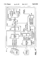
- FIGS. 8A, 8B together are a block diagram of an ultrasound system for measuring volumetric flow to illustrate the preferred embodiment of the invention.
- FIG. 9 is a circuit diagram illustrating in more detail a portion of the circuit in FIG. 7B.
- FIG. 10 a block diagram illustrating in more detail one implementation of the circuit of FIG. 9.
- FIG. 11 illustrates another implementation and parallel to that of FIG. 10.
- FIG. 12 is a schematic circuit diagram illustrating a circuit that may be useful for the implementation of FIG. 11.
- FIG. 13 is a schematic representation of a lookup table for mapping inputs onto values for the purpose of counting qualified pixels, to illustrate the contents of the lookup tables in FIGS. 9-11.
- FIG. 14 is a schematic representation of the implemented function of the lookup table of FIG. 13.
- FIG. 15 is a schematic representation of a lookup table for mapping inputs onto values for the purpose of accumulating qualified velocity values, to illustrate the contents of the lookup tables in FIGS. 9-11.
- FIG. 16 is a schematic representation of the implemented function of the lookup table of FIG. 15.
- FIG. 2A is a schematic view of a portion of a blood vessel 2 within a body 20 with a surface 20a.
- the scan plane 22 intersects vessel 2 as shown.
- a Cartesian coordinate system XYZ is shown in FIG. 2 where the Z axis is perpendicular to the body surface 20a.
- the axis 10 of the vessel has a projection on surface 20a which is parallel to the X axis.
- the transducer (not shown) that transmits ultrasound signals along scan lines in the scan plane 22 is oriented so that the scan plane 22 is normal to the body surface 20a and at an angle ⁇ to the YZ plane shown more clearly in FIG. 2B. As described below in more detail, it is preferable to orient the scan plane so that it is in the YZ plane.
- FIG. 2B is a top view of the section of the blood vessel 2 and scan plane 22 of FIG. 2A together with the transducer 30 generating ultrasound signals in the scan plane for illustrating the invention.
- the scan plane 22 is at an angle ⁇ to the XZ plane and is normal to the body surface 20a.
- the preferred embodiment is described in reference to FIGS. 2A, 2B, 3-7. Before the preferred embodiment is described, it will be useful to consider the general case shown in FIG. 2C.
- FIG. 2C is a side view of the section of the blood vessel and scan plane of FIG. 2A viewed along the Y axis but where the scan plane is tilted to an inclined position (i.e. not perpendicular) relative to the surface of the body imaged for illustrating the invention.
- the Z axis is normal to the surface of the body, and the angles in the figure are defined as:
- ⁇ T the angle from the Z axis to the plane containing the scan plane of the transducer. This angle may be the result of tilting the transducer or steering the beams in an elevational direction or a combination of these;
- ⁇ V the angle that the vessel makes with respect to the Z axis
- ⁇ VT the angle that the scan plane makes with respect to the vessel
- ⁇ VT ⁇ V - ⁇ T
- the orientation of the blood vessel 2 with respect to the scanning plane is defined by two polar coordinate angles ⁇ VT and ⁇ (defined above with respect FIG. 2B), as shown in FIG. 2C.
- V Y represent the component of the fluid flow velocity along the Y axis
- V XZ the component of the fluid flow velocity in the XZ plane, as shown in FIG. 2C.
- x, y, z are the unit vectors along the X, Y, Z axes respectively, then the actual velocity actual V actual of the fluid flow is given by:
- FIGS. 2D-2H illustrate five different types of transducers that can be used to steer the ultrasound beam along either a constant or varying ⁇ S . While transducers in these five types of steering formats can be used, it will be understood that formats other than these can also be used and are within the scope of this invention.
- volumetric flow it is also necessary to determine the actual area A actual which is perpendicular to the direction of the fluid flow. If ultrasound images are used to measure the actual area, the measured quantity A meas will need to be corrected according to the following relation: ##EQU2## If one uses the above equations for V meas and A meas , to determine V actual and A actual , one can determine the volume flow associated with each sample. One can then sum all of these flows to obtain a total volume flow.
- ⁇ VT ⁇ V - ⁇ T .
- FIGS. 3-7 The above procedure in simplifying the two equations to obtain volumetric flow measurements will be illustrated in more detail in reference to FIGS. 3-7.
- a transducer 30 is applied at a body/transducer interface 20a' with axis 26 of the transducer parallel to the Z axis and normal to surface 20a of the body.
- the transducer is rotated about its axis 26 until the gray-scale or B-mode image of a cross-section of vessel 2 has the smallest area. This is illustrated further in reference to FIGS. 4 and 5.
- FIG. 4 is a top view of vessel 2 looking from the surface 20a into the body 20.
- FIG. 4 is a top view of vessel 2 looking from the surface 20a into the body 20.
- FIG. 5 is a schematic view of a displayed ultrasound image 40 obtained when an ultrasound system including transducer 30 is used to obtain the B-mode image of a cross-section of vessel 2.
- FIGS. 4 and 5 illustrate the views of the cross-sections of vessel 2 in three different positions A, B, C. Where the scan plane 22 intersects the vessel obliquely, such as at position C, the B-mode image appears on screen 40 as an elongated ellipse c. As the transducer is rotated so that the scan plane is in position B in FIG. 4, the cross-section of the vessel in image 40 is reduced from c to b. Where the cross-section of the vessel 2 has the smallest area, such as a, the scan plane is in position A in FIG. 4.
- the scan plane 22 When the transducer is in this position, the scan plane 22 would then be substantially perpendicular or normal to the X axis, and is in the YZ plane.
- the angle ⁇ would be substantially 90 degrees, since the projection of axis 10 of the vessel on surface 20a is parallel to the X axis. Therefore, as long as the angle ⁇ is maintained to be substantially 90 degrees during measurements, it is possible to remove the dependence of the measurements on the angle ⁇ .
- the smallest cross-sectional area of the vessel can also be obtained by using F-mode data or other Doppler ultrasound data.
- F-mode data or other Doppler ultrasound data.
- FIG. 6 is the same side view of the vessel and transducer as that in FIG. 3, except that the transducer 30 has been rotated until ⁇ is maintained to be substantially 90 degrees during measurements, and where the transducer has been tilted in the XZ plane to three different positions 30(1), 30(2), and 30(3) as shown in FIG. 6 in order to tilt the scan planes to three different angles ⁇ 1 , ⁇ 2 and ⁇ 3 .
- the tilting of the scan planes can also be accomplished by beam steering without actually moving the transducer.
- volumetric flow Q is normally measured in units of milliliters per second.
- the instantaneous volumetric flow Q(t) is a function of time, and is given as the integral of the surface integral of the instantaneous velocity v(x,y,t) at position (x,y): ##EQU3## over the instantaneous cross-sectional area A(t) of the vessel.
- the time-averaged volumetric flow of Q is: ##EQU4##
- the selected time interval is typically one or more integral cardiac or heart cycles, or might be only during a certain interval within the cardiac cycle. If the velocity is a constant V over time and over the flow surface intersected by the scan plane, and the surface is a constant area A, then: ##EQU5## This product relation will be used to estimate volumetric flow as shown below.
- transducer 30 is tilted in the XZ plane to different positions where ⁇ VT having the value 0°, 90°, 180° or 270° is avoided since either the velocity or area is not measurable at these angles.
- ⁇ VT having the value 0°, 90°, 180° or 270°
- velocity and area measurements can be taken with the transducer in these positions.
- the transducer is tilted or the scan line steered in the elevational direction so that ⁇ VT is in the range of about 15 to 75 degrees, or more specifically about 30 to 60 degrees.
- the exact angle need not be known; however, angles closer to 45° plus integer multiples of 90° are better than angles that deviate from this by a large number of degrees.
- a pix represents the constant area associated with each pixel.
- the imaging frames are designated by index m, and each frame separated from the next frame by ⁇ t seconds.
- ⁇ t seconds Rather than calculating the instantaneous volumetric flow associated with each frame, one may simply determine for each frame or for a number of frames the average velocity V and the average area A which have been corrected for the angular dependence on ⁇ . Then the averaged volumetric flow is simply given by the product VA.
- the constant Apix is computed based upon the display settings. Assuming that the time-averaging interval (0, T) is covered by M frames for m ranging from 0 to M-1, then the following equations may be used to eliminate the explicit dependence of the measurement on ⁇ in the two simplified equations (1) and (2) above.
- index k (ranging from 1 to K) is used to designate the averaged measurements for A k and V k at an angle ⁇ k , so that the approximations below will hold: ##EQU6## where p k (m,i,j) is one if the pixel is color activated and 0 if the pixel is not activated, which means that the following holds: ##EQU7## Ideally, ##EQU8## but noise and approximation makes these equations inaccurate.
- Deviations from ideal can be used to form the error: ##EQU10## Forming the total squared error E or f (A, V) over a number of angles: ##EQU11## The squared error can be minimized using a least mean square error estimate calculation so that the averaged area A and averaged velocity V will not explicitly depend on angle ⁇ k .
- N 2
- the exact solution and the least mean square error calculation are the same. While preferably, the angular dependence on ⁇ can be eliminated as described above, in some applications, it may be adequate to perform a direct measurement of the angle ⁇ as described above in reference to FIG. 1. In such event, all one has to do is to orient the transducer 30 so as to eliminate the dependence upon the angle ⁇ such as by the procedure described above in reference to FIGS. 3-6, and the actual cross-sectional area and the actual average velocity may then be obtained by multiplying the result obtained in one measurement by appropriate factors using knowledge of ⁇ . Such and other variations are within the scope of the invention.
- transducer 30 is of the type where the scan lines are in the azimuth plane of the transducer so that it is generally not possible to change direction of the scan line in the elevational direction of the transducer. Where it is possible to steer the scan line both in the azimuth and elevation directions, rotation and tilting of the transducer may not be required so that the rotation and the tilting of the scan plane described above may be accomplished by applying appropriate signals with the proper phase relationship in a manner known to those skilled in the art.
- the term "skin/transducer interface position" means that the contact point between the transducer and the surface of the body 20a does not change when the transducer is rotated or tilted (or tipped) to make measurements at the different imaging angles.
- rotationally orienting means rotating the transducer while its axis is perpendicular or normal to the surface of the body.
- tilt angle means the angle that the axis of the transducer makes with the normal direction to the surface of the body.
- FIGS. 8A, 8B together are a block diagram of an ultrasound system to illustrate the preferred embodiment of the invention.
- system 100 includes transducer 30 connected to an ultrasound beamformer 102 that applies appropriate signals to the transducer for transmitting ultrasound signals towards a body that includes a vessel containing moving fluid such as blood (not shown).
- the ultrasound signals are transmitted sequentially along scan lines (not shown) spanning a scan plane in a region of interest.
- the echoes of the ultrasound signals reflected off of the body including the moving fluid and vessel are detected by the transducer 30 whose output is applied to the beamformer 102.
- the output of the beamformer is processed by a B-mode processing unit 104 to provide a gray-scale, B-mode image.
- the output of the beamformer is also applied to a F-mode processing unit 106 in which the received signal is processed to extract velocity information which is stored in CINE memory 108 which also stores the B-mode image from the B-mode processing unit.
- CINE memory 108 which also stores the B-mode image from the B-mode processing unit.
- Either one or both of the B-mode and F-mode images may be retrieved and scan converted by scan conversion 110 and applied to two frame buffers 112, 114: Image plane 0 and image plane 1.
- the reading and writing of image information into or out of memory 108 is controlled by microprocessor 120 employing a write address unit 122 and a read address unit 124.
- Each of the two frame buffers 112, 114 may be divided into sections, each for storing data of an image type, such as B-mode, color-energy, color-variance, color-velocity data.
- Both buffers 112, 114 include a section for storing the identity of pixels within the region designated by a user, or the region ID.
- the user may designate the region or regions where the volumetric flow is to be calculated, referred to herein as calculation area, by means of a trackball input 130.
- the user may simply draw an outline of the regions where volumetric flow is of interest on a display device. Such input will be processed by microprocessor 120 and recorded in the region ID section of the frame buffers. In some applications, the outline drawn by the user is actually shown on the display screen.
- the use of two frame buffers facilitates the display process.
- the output of multiplexer 132 includes the different image type data and/or region Id.
- image data is applied to display device 140 for displaying B-mode and F-mode images in a manner known to those skilled in the art.
- the image data is also applied along signal path 136 to parameter selection 142 and the region Id information is applied to calculation area accumulators 144.
- Parameter selection 142 in response to the microprocessor selects the appropriate bits of information from the B-mode and F-mode information and supplies such bits to the lookup table 146.
- Lookup table 146 maps such bits onto values that are supplied to accumulators 144. Instead of lookup tables 146, other mapping devices such as threshold or scaling devices may also be used.
- the operator In operation of the system of FIGS. 8A, 8B, the operator displays the B-mode image and traces out one to N calculation areas within which volume flow measurements are to be made.
- the area enclosed by each of the uniquely enclosed calculation area of interest outlines is given a unique identifier which is placed into the region Id bit locations of the image memory planes 112, 114 corresponding to the enclosed area as shown on the display device.
- FIG. 9 is a schematic circuit diagram illustrating in more detail the functions and construction of parameter selection 142, accumulators 144 and lookup table 146.
- parameter selection 142 includes two parameter select logic circuits 142a, 142b for selecting the appropriate B-mode and F-mode information to determine the actual area where there is fluid flow, and flow velocity.
- the bits selected by logic 142a are supplied to lookup table 146a which applies a selection criteria to such bits to determine whether there is valid fluid flow data in the particular pixel for displaying the data. If there is, table 146a would output 1 to AND-gate 150. Otherwise, it will supply a 0 to the AND-gate.
- the region Id enable bit of line 136 is also supplied to AND-gate 150, so that if the particular pixel data processed is not within the calculation area designated by the user, a 0 is supplied to AND-gate 150 to force the gate output to 0 so that such pixel is not counted in the accumulator 144a; otherwise a 1 is supplied to gate 150.
- the B-mode information and/or F-mode information may be used to determine whether there is flow in the particular pixel and whether the pixel should be counted as part of the actual area where there is fluid flow. For example, if the amplitude of the B-mode signal is high, this may indicate that the color present in such pixel may not be a reliable indication of fluid flow in such pixel so that the lookup table 146a should output a 0 rather than a 1. In some applications, just the F-mode data may be adequate for determining the validity of the data. The same considerations also apply to qualifying the validity of the velocity data processed in the parallel path described below.
- Parameter select logic 142b would select the appropriate bits of information from the F-mode and B-mode information from multiplexer 132 and supply such bits to the lookup table 146b.
- table 146b applies a selection criteria to the bits received to output a value for velocity if the data is qualified and a 0 if the data is not qualified as valid to AND-gate 154, which may be a multi-bit gate.
- AND-gate 154 is also controlled by the region Id enable bit from the multiplexer 132 in a manner similar to AND-gate 150.
- Adder 156 then adds the output of AND-gate 154 to the stored value in register 144b and supplies the updated value to replace that stored in accumulator register 144b.
- Frame buffers 112 and 114 each stores an entire frame of information. After an entire frame of information has been processed through the two signal paths in FIG. 9, accumulator 144a will contain a count indicating the number of qualified pixels in the vessel where there is significant fluid flow and accumulator 144b will contain a summed value of a parameter such as velocity. The values stored in the two registers 144a, 144b are then read by the microprocessor through two tri-state buffers 158 controlled by the microprocessor and stored in the microprocessor memory.
- the above-described process for counting the number of qualified pixels where there is actual flow and integration to obtain a sum of qualified velocity values may be performed for each of multiple frames. By multiplying the number of pixels by the area per pixel an area measurement is obtained for each of the multiple frames. By dividing the sum of qualified velocity values by the number of qualified pixels, an averaged velocity for each of the several frames is obtained. Processing and display of the result may occur immediately after real-time acquisition has occurred or it may occur at a later point in time as the data is read out of the cine memory. While in the preferred embodiment, the cross-sectional area is given by counting qualified pixels and multiplying the count by the pixel area, it will be understood that other methods of integrating qualified area portions may be used and are within the scope of the invention.
- One possible processing sequence for acquired frames might be:
- microprocessor 120 After a designated number of frames have been processed, microprocessor 120 then computes an averaged area measurement and an averaged velocity for the multiple frames. These then are the measured area and averaged velocity values for a particular angle of measurement ⁇ between the scan plane and the fluid flow in the vessel. Once the processor has all the data required to perform a given calculation, it may perform the calculation and display the result.
- the display may be in the form of either a numeric value or a waveform display. The actual order of displaying frames also does not need to correspond to the order in which the frames were acquired.
- microprocessor 120 provides the value via line 160 to the text and graphics plane 162. For waveforms the data is also sent to the text and graphics plane.
- the angle ⁇ may actually be measured so that the values stored in the two registers may be corrected using the information obtained and measured to yield the actual area and velocity and therefore the volumetric flow.
- the values may be stored in a microprocessor memory as the area measurement value and averaged velocity for a particular scanning and measuring position such as one of the three illustrated in FIG. 6.
- the transducer may then be tilted to a different angle as described above in reference to FIG. 6 and the above data acquisition process repeated to obtain another measured value of the averaged area and averaged velocity to be stored at the microprocessor memory. This process may be repeated if desired to obtain multiple values of the measured area and velocity.
- the microprocessor then performs the least mean square error estimate calculations described above to obtain the values of area and velocity that will minimize the mean square error.
- the product of these two quantities then yields a volumetric flow in vessel 2.
- the data acquired at each angle may be stored in cine memory and the processing can occur later.
- the velocity data is used to determine whether there is qualified blood flow in a certain pixel or area, so as to decide whether such pixel or area is to be counted or added to arrive at the total cross-sectional area of the vessel. It is possible to use data other than velocity of the blood flow in this process. For example, non-zero energy or variance of velocity of the flow within the calculation area may be used instead. Other types of data may also be used, such as B-mode data, or other ultrasound echo information. An estimate of the cross-sectional area of the vessel is then obtained by adding or integrating areas associated with such information. All such variations are within the scope of the invention.
- the acoustic data associated with each frame of data to be processed along with the respective time stamp i.e., the time at which the frame was acquired
- the time stamp i.e., the time at which the frame was acquired
- various reference signals occurred e.g., the Rwave trigger in a cardiac cycle
- Physio unit 103 in FIG. 8A acquires electrocardiograms from which Rwave trigger signals are derived. These trigger signals together with the acoustic data may be passed to the display directly or may be passed at a later time via a cine operation.
- the display subsystem consists of scan converting the acoustic data and placing it into a specified image memory plane; once the entire image has been scan-converted, one will at a later vertical blank signal read the scan-converted signal from the image memory and process the scan-converted data on its way to the display device.
- consecutive frames of acoustic data spanning several Rwave cycles may be obtained.
- the time stamps associated with the acquired frames as well as the time stamps for any reference signals are also stored.
- a couple of examples are:
- the above frames might be displayed in the same manner as that described above.
- the processor may then obtain averages from the 24 resulting values (i.e., sum over all j and k for each of the three frames 1, 2, 3, and divide each of the sums by 24) of the velocity and pixel counts for each of the three angles scanned to obtain three sets of averaged values.
- a least mean square error calculation is then performed to find an area value and a velocity value that would minimize the error for the data acquired at the three angles. These values would then be used to calculate volume flow.
- An alternative approach might be for the processor to average for each angle the three values obtained at the same relative offset with respect to the start of the Rwave (i.e., sum over all j, for particular value(s) of k). This results in a separate value of summed velocity and pixel count to calculate an instantaneous volume flow.
- the averaging is performed over a group of frames having the same time offset relative to a cardiac event such as an Rwave trigger. For example the averaging may be performed for frames F(1,1,2), F(1,2,2) and F(1,3,2) to obtain an averaged area measurement and averaged velocity for the second frame in the cardiac cycle for unique scan angle 1.
- each of the three groups of frames includes three frames, and each of the frames is the second frame (k has the value 2) after the Rwave trigger.
- the frames need not be displayed in order but might instead be displayed in an order corresponding to the lowest offset with respect to the start or trigger of the Rwave.
- FIG. 10 One implementation of the embodiment of FIG. 9 is illustrated in more detail in the block diagram of FIG. 10, which includes circuit functions equivalent to the image planes of FIG. 8A and the circuit 200 which performs all the functions of FIG. 9.
- the parameter selection, lookup table and pixel accumulator circuit 200 receives F-mode and B-mode data from three image planes 212, 214 and 216 which are respectively the Image Type 0, Image Type 1 and Image Type 2 planes in buffers 112, 114 of FIG. 8A. Data from the three planes are supplied in parallel to two multiplexers 242a and 242b controlled by two select lines A select, B select from register 202.
- Each of the two multiplexers selects the appropriate bits of information from such inputs and supplies such information to a corresponding random access memory lookup table 246a or 246b.
- the two lookup tables are controlled by page selects PAGE A , PAGE B from register 202.
- Circuit 200 includes two pairs of accumulators: a first pair 244a(1), 244a(2) and a second pair 244b(1), 244b(2). In each pair, one is for accumulating or integrating even-numbered pixels and the other for integrating or accumulating odd-numbered pixels. The two accumulators in each pair for accumulating even and odd pixels are arranged in parallel to speed up the accumulation process.
- the two lookup tables map the received bits onto selected stored values under the control of the two page signals and supply outputs to the accumulators through two sign extension controls 248, with each of the controls supplying sign extended signals to a pair of two accumulators.
- Each of the four accumulators has sixteen registers addressed by a four bit region address signal from pixel control map 218 which performs a function similar to the region Id section of the image planes of FIG. 8A. In this manner, each of the four accumulators is capable of accumulating up to sixteen different calculation areas.
- Pixel control map 218 sends an extra two bits for A enable and B enable control, which permits all four accumulators to be used for accumulating a single parameter such as area or velocity, without accumulating the values of a second parameter.
- the implementation of the circuitry of FIG. 10 is illustrated in more detail in a microfiche appendix entitled "Ultrasound System for Flow Measurements Implementation No. 1,” which is attached hereto and is an integral part of this application.
- FIG. 11 illustrates another implementation parallel to that of FIG. 10; the implementation in FIG. 11 is illustrated in more detail in microfiche appendix entitled "Ultrasound System for Flow Measurements Implementation No. 2," which is attached hereto and is an integral part of this application.
- system 300 has essentially the same overall structure as that in FIG. 10 except that the number of multiplexers (e.g. 342), random access memory lookup tables (e.g. 346) and accumulators (e.g. 344(1), 344(2)) have been reduced for a more cost-effective implementation.
- control register file 302 A/B select register 304, and multiplexers 306, 308 are used for controlling parameter select multiplexer 342, random access memory lookup table 346, sign extension control 348, and accumulators 344 (1), 344 (2).
- FIG. 12 is a schematic circuit diagram illustrating a circuit 350 that may be useful for the implementation of FIG. 11. Since it takes considerable time to read a value from each of the two accumulators 344(1), 344(2), when such value is read and sent to adder 352 as in FIG. 11, such value may already be stale and should be replaced by a more updated value instead.
- the circuit of FIG. 12 compensates for this by using the circuit 350 where a region Id collision detector 351 compares the region Id that is associated with the value at the input to the accumulator with the region Id associated with the value being written to memory 344', and selects which of the multiplexer 360 inputs to be applied to adder 352'.
- FIG. 13 is a schematic representation of a lookup table for mapping input values onto values for the purpose of counting qualified pixels, to illustrate the contents of the lookup tables 146a, 246a and a corresponding portion of 346 described above in reference to FIGS. 9-11.
- both velocity and B-mode values are sent to the lookup table which maps the velocity and B-mode values to a value which is supplied to its output.
- FIG. 14 is a schematic representation of the implemented function of the lookup table of FIG. 13. As shown in FIG. 14, the lookup table would output a "1" when the B-mode intensity is below a predetermined threshold 402 and if the velocity is above a threshold 404 in one direction or above a threshold 406 in the other direction. Otherwise, the lookup table would supply a zero at its output.
- FIG. 15 is a schematic representation of a lookup table for mapping inputs onto values for the purpose of accumulating qualified velocity values, to illustrate the contents of the lookup tables 146b, 246b and a corresponding portion of table 346 described above in reference to FIGS. 9-11.
- both velocity and B-mode values are sent to the lookup table which maps the velocity and B-mode values to a value which is supplied to its output.
- FIG. 16 is a schematic representation of the implemented function of the lookup table of FIG. 15. As shown in FIG. 16, the lookup table would output a baseline corrected velocity value when the B-mode intensity is below a predetermined threshold 412 and if the velocity is above a threshold 414 in one direction or above a threshold 416 in the other direction.
- V true time and area averaged velocity surface integral
- a i the time averaged measurement of cross-sectional area at angle ⁇
- V i the time and area averaged measurement of velocity surface integral at the angle ⁇
- velThresh is the velocity threshold. If the absolute value of the velocity input (treated as an 8-bit signed number) into the hardware lut is below this threshold, then the output of the lut will be set to 0. If the b-mode input is above the BmodeThreshold level, then the output will also be set to 0. Otherwise the output will be set to a 1. This function mimics the thresholding functions performed in the color mapping.
- the mapptr is a pointer to the hardware lut RAM page that will be loaded with function A.
- the LUT is organized as shown in FIGS. 13 and 14:
Landscapes
- Engineering & Computer Science (AREA)
- Physics & Mathematics (AREA)
- Radar, Positioning & Navigation (AREA)
- Remote Sensing (AREA)
- Acoustics & Sound (AREA)
- Health & Medical Sciences (AREA)
- Life Sciences & Earth Sciences (AREA)
- Computer Networks & Wireless Communication (AREA)
- General Physics & Mathematics (AREA)
- Pathology (AREA)
- Medical Informatics (AREA)
- Nuclear Medicine, Radiotherapy & Molecular Imaging (AREA)
- Hematology (AREA)
- Radiology & Medical Imaging (AREA)
- Biomedical Technology (AREA)
- Heart & Thoracic Surgery (AREA)
- Biophysics (AREA)
- Molecular Biology (AREA)
- Surgery (AREA)
- Animal Behavior & Ethology (AREA)
- General Health & Medical Sciences (AREA)
- Public Health (AREA)
- Veterinary Medicine (AREA)
- Ultra Sonic Daignosis Equipment (AREA)
Abstract
Description
v.sub.XZ sin θ.sub.V x+v.sub.Y y+V.sub.XZ cos θ.sub.V z
V.sub.means =V.sub.actual ×cos θ.sub.VT (1)
A.sub.meas =A.sub.actual / sin θ.sub.VT (2)
__________________________________________________________________________
  REPEAT FOR (selected set of acquisition angles) {
   FOR EACH DISPLAYED FRAME {
    Processor waits for the start of vertical blank (Fig.8A)
     Processor acquires from the hardware for the previously displayed
frame
      FOR EACH REGION.sub.-- ID {
        read from the hardware the total number of pixels displaying
qualified color as
       calculated by the hardware
        read from the hardware the sum of all qualified velocity values
at pixels in a given region
      }
     processor clears accumulators
    }
  }
__________________________________________________________________________
__________________________________________________________________________
        Let F(i,j,k) represent the kth acoustic frame acquired
relative to the
        jth Rwave trigger for the ith unique angle of scan. One might
then have
        acquired the following frames of data:
F(1,1,1),F(1,1,2),F(1,1,3),F(1,1,4),F(1,1,5),F(1,1,6),F(1,1,7),F(1,1,8)
F(1,2,1),F(1,2,2),F(1,2,3),F(1,2,4),F(1,2,5),F(1,2,6),F(1,2,7),F(1,2,8)
F(1,3,1),F(1,3,2),P(1,3,3),F(1,3,4),F(1,3,5),F(1,3,6),F(1,3,7),F(1,3,8)
F(2,1,1),F(2,1,2),F(2,1,3),F(2,1,4),F(2,1,5),F(2,1,6),F(2,1,7),F(2,1,8)
F(2,2,1),F(2,2,2),F(2,2,3),F(2,2,4),F(2,2,5),F(2,2,6),F(2,2,7),F(2,2,8)
F(2,3,1),F(2,3,2),F(2,3,3),F(2,3,4),F(2,3,5),F(2,3,6),F(2,3,7),F(2,3,8)
F(3,1,1),F(3,1,2),F(3,1,3),F(3,1,4),F(3,1,5),F(3,1,6),F(3,1,7),F(3,1,8)
F(3,2,1),F(3,2,2),F(3,2,3),F(3,2,4),F(3,2,5),F(3,2,6),F(3,2,7),F(3,2,8)
F(3,3,1),F(3,3,2),F(3,3,3),F(3,3,4),F(3,3,5),F(3,3,6),F(3,3,7),F(3,3,8)
__________________________________________________________________________
A=A.sub.i sin θ
V=V.sub.i / cos θ
sin θ=A/A.sub.i
cos θ=V.sub.i /V
__________________________________________________________________________
*  Author: Ismayil Guracar
*  Date: 4/26/95
*  Copyright: Acuson
*/
Load
   VolumeFlowFunctionA(velThresh, BmodeThresh, mapptr)
int
   velThresh;
int
   BmodeThresh;
int
   *mapptr;
int
   vel, b, flag;
for
   (vel=0; vel<256; vel++)
 {
if (vel<128)
if (vel<velThresh)
flag=0; /* color is off */
else
flag=1; /* color is on */
else /* vel negative */
if ((255-vel)<velThresh) /* absolute value of velocity */
flag=0; /* color is off */
else
flag=1; /* color in on */
for (b=0; b<BmodeThresh; b++)
mapptr[(vel<<8) +b] = flag;
for (b=BmodeThresh; b<256; b++)
mapptr[(vel<<8) +b] = 0; /* set color off */
 }
}
*
*
* LoadVolumeFlowFunctionB(velThresh, BmodeThresh, BaselineShift, mapptr)
*
*  velThresh is the velocity threshold. If the absolute value of the
*  velocity input (treated as an 8-bit signed number)
*  into the hardware lut is below this threshold, then the
*  output of the lut will be set to 0. If the b-mode input
*  is above the BmodeThreshold level, then the output will also
*  be set to 0. Otherwise the output will be set to the baseline
*  shift corrected velocity input.
*
*  The BaselineShift value operates as follows:
*
*
* positive values:
*
* In  0 . . . v . . . 127+Baseline Shift
* Out  0 . . . v/2 . . . 127baseline Shift/2
*
*
* negative values:
*
* In  255 . . .  v  . . . 128-BaselineShift
* Out (-1) . . . -(256-v)/2 . . . ((-128) +BaselineShift)/2
__________________________________________________________________________
__________________________________________________________________________
*    Copyright: Acuson
*/
iead VolumeFlowFunctionB(velThresh, BmodeThresh, BaselineShift, mapptr)
int  velThresh;
int  BmodeThresh;
int  *mapptr;
int  vel, b, flag;
int  baselineCorrectedVelocity;
for  (vel=0; vel<256; vel++)
*
*    implement velocity threshold
*/
 if (vel<128)
if (vel<velThresh)
flag=0; /* color is off */
else
flag=1; /* color is on */
 else /* vel negative */
if ((255-vel)<velThresh) /* absolute value of velocity */
flag=0; /* color is off */
else
flag=1; /* color in on */
/*
 *   calculate the baseline shift corrected velocity
 *   The velocity will be scaled by a factor of two
 *   to account for the increase in dynamic range that
 *   the baseline shift process requires.
 */
 if (vel<(127+BaselineShift)) /* positive value */
{
 baselineCorrectedVelocity = vel/2; /* make sure sign bit is not set */
}
 else
{
 baselineCorrectedVelocity = - (256-vel)/2; /* output a negative value
*/
}
/*   implement b-mode threshold and output corrected velocity
 *   to the lut.
 */
 for (b=0; b<BmodeThresh; b++)
mapptr[(vel<<8)+b] = flag * baselineCorrectedVelocity;
 for (b=BmodeThresh; b<256; b++)
mapptr[(vel<<8)+b] = 0; /* set color off */
}
}
__________________________________________________________________________
Claims (61)
Priority Applications (3)
| Application Number | Priority Date | Filing Date | Title |
|---|---|---|---|
| US08/432,858 US5623930A (en) | 1995-05-02 | 1995-05-02 | Ultrasound system for flow measurement |
| AU55734/96A AU5573496A (en) | 1995-05-02 | 1996-04-25 | Ultrasound system for flow measurement |
| PCT/US1996/005738 WO1996034562A1 (en) | 1995-05-02 | 1996-04-25 | Ultrasound system for flow measurement |
Applications Claiming Priority (1)
| Application Number | Priority Date | Filing Date | Title |
|---|---|---|---|
| US08/432,858 US5623930A (en) | 1995-05-02 | 1995-05-02 | Ultrasound system for flow measurement |
Publications (1)
| Publication Number | Publication Date |
|---|---|
| US5623930A true US5623930A (en) | 1997-04-29 |
Family
ID=23717874
Family Applications (1)
| Application Number | Title | Priority Date | Filing Date |
|---|---|---|---|
| US08/432,858 Expired - Lifetime US5623930A (en) | 1995-05-02 | 1995-05-02 | Ultrasound system for flow measurement |
Country Status (3)
| Country | Link |
|---|---|
| US (1) | US5623930A (en) |
| AU (1) | AU5573496A (en) |
| WO (1) | WO1996034562A1 (en) |
Cited By (73)
| Publication number | Priority date | Publication date | Assignee | Title |
|---|---|---|---|---|
| US5967987A (en) * | 1997-12-18 | 1999-10-19 | Acuson Corporation | Ultrasonic system and method for measurement of fluid flow |
| US6048314A (en) * | 1998-09-18 | 2000-04-11 | Hewlett-Packard Company | Automated measurement and analysis of patient anatomy based on image recognition |
| US6071242A (en) * | 1998-06-30 | 2000-06-06 | Diasonics Ultrasound, Inc. | Method and apparatus for cross-sectional color doppler volume flow measurement |
| US6111816A (en) * | 1997-02-03 | 2000-08-29 | Teratech Corporation | Multi-dimensional beamforming device |
| WO2000072756A1 (en) * | 1999-05-28 | 2000-12-07 | Vuesonix Sensors, Inc. | Device and method for mapping and tracking blood flow and determining parameters of blood flow |
| US6213949B1 (en) * | 1999-05-10 | 2001-04-10 | Srs Medical Systems, Inc. | System for estimating bladder volume |
| US6241677B1 (en) * | 1996-12-04 | 2001-06-05 | Acuson Corporation | Method and apparatus for ultrasound image quantification |
| US6245018B1 (en) * | 1997-12-15 | 2001-06-12 | Medison Co., Ltd. | Ultrasonic color doppler imaging system capable of discriminating artery and vein |
| US6292433B1 (en) | 1997-02-03 | 2001-09-18 | Teratech Corporation | Multi-dimensional beamforming device |
| US6293914B1 (en) | 1998-08-31 | 2001-09-25 | Acuson Corporation | Ultrasonic system and method for measurement of fluid flow |
| US6322509B1 (en) * | 2000-05-01 | 2001-11-27 | Ge Medical Systems Global Technology Company, Llc | Method and apparatus for automatic setting of sample gate in pulsed doppler ultrasound imaging |
| WO2001071648A3 (en) * | 2000-03-23 | 2002-03-28 | Cross Match Technologies Inc | Piezoelectric identification device and applications thereof |
| US6383139B1 (en) | 1996-06-28 | 2002-05-07 | Sonosite, Inc. | Ultrasonic signal processor for power doppler imaging in a hand held ultrasonic diagnostic instrument |
| US6482161B1 (en) | 2000-06-29 | 2002-11-19 | Acuson Corporation | Medical diagnostic ultrasound system and method for vessel structure analysis |
| US20030001459A1 (en) * | 2000-03-23 | 2003-01-02 | Cross Match Technologies, Inc. | Secure wireless sales transaction using print information to verify a purchaser's identity |
| US6503202B1 (en) | 2000-06-29 | 2003-01-07 | Acuson Corp. | Medical diagnostic ultrasound system and method for flow analysis |
| US20030018264A1 (en) * | 2001-06-19 | 2003-01-23 | Yoichi Suzuki | Ultrasonic imaging apparatus |
| US6517488B1 (en) | 2000-06-29 | 2003-02-11 | Acuson Corporation | Medical diagnostic ultrasound system and method for identifying constrictions |
| US6663568B1 (en) * | 1998-03-11 | 2003-12-16 | Commonwealth Scientific And Industrial Research Organisation | Ultrasound techniques |
| US6682483B1 (en) | 1999-05-28 | 2004-01-27 | Vuesonix Sensors, Inc. | Device and method for mapping and tracking blood flow and determining parameters of blood flow |
| US20040019278A1 (en) * | 2000-05-26 | 2004-01-29 | Kenneth Abend | Device and method for mapping and tracking blood flow and determining parameters of blood flow |
| US6721235B2 (en) | 1997-02-03 | 2004-04-13 | Teratech Corporation | Steerable beamforming system |
| WO2004036151A1 (en) * | 2002-10-17 | 2004-04-29 | Endress + Hauser Flowtec Ag | Flowmeter |
| US20040138564A1 (en) * | 1996-06-28 | 2004-07-15 | Sonosite, Inc. | Ultrasonic signal processor for a hand held ultrasonic diagnostic instrument |
| US6780155B2 (en) | 2001-12-18 | 2004-08-24 | Koninklijke Philips Electronics | Method and system for ultrasound blood flow imaging and volume flow calculations |
| US20040220474A1 (en) * | 2002-03-20 | 2004-11-04 | Kenneth Abend | Determining the power of an ultrasound reflection using an autocorrelation technique |
| US6814703B2 (en) * | 2001-09-28 | 2004-11-09 | Kabushiki Kaisha Toshiba | Apparatus and method for ultrasonic diagnostic imaging using a contrast medium |
| US20040254468A1 (en) * | 2003-03-27 | 2004-12-16 | Vuesonix Sensors, Inc. | Mapping and tracking blood flow using reduced-element probe |
| US20040254461A1 (en) * | 2002-03-20 | 2004-12-16 | Ackerman William H. | Acoustic beam shaping by pulse power modulation at constant amplitude |
| US20040267127A1 (en) * | 1999-05-28 | 2004-12-30 | Vuesonix Sensors, Inc. | Transmitter patterns for multi beam reception |
| US20050004468A1 (en) * | 2003-03-17 | 2005-01-06 | Vuesonix Sensors, Inc. | Increased sensitivity for 4-D ultrasound imaging and for 4-D doppler ultrasound imaging |
| US20050004464A1 (en) * | 2003-03-14 | 2005-01-06 | Vuesonix Sensors, Inc. | Method and apparatus for forming multiple beams |
| US20050004461A1 (en) * | 1999-05-28 | 2005-01-06 | Kenneth Abend | Pulse interleaving in doppler ultrasound imaging |
| US6842401B2 (en) | 2000-04-06 | 2005-01-11 | Teratech Corporation | Sonar beamforming system |
| US20050124885A1 (en) * | 2003-10-29 | 2005-06-09 | Vuesonix Sensors, Inc. | Method and apparatus for determining an ultrasound fluid flow centerline |
| US20050137479A1 (en) * | 2003-12-19 | 2005-06-23 | Haider Bruno H. | Method and apparatus for flow parameter imaging |
| US20060074309A1 (en) * | 2002-11-06 | 2006-04-06 | Odile Bonnefous | Phased array acoustic system for 3d imaging of moving parts |
| US20060238077A1 (en) * | 2000-03-23 | 2006-10-26 | Scott Walter G | Method for obtaining biometric data for an individual in a secure transaction |
| US20060241459A1 (en) * | 2005-02-08 | 2006-10-26 | Tai Alan C | Automatic signal-optimizing transducer assembly for blood flow measurement |
| US7236616B1 (en) | 1999-08-09 | 2007-06-26 | Cross Match Technologies, Inc. | Biometric piezo scanner |
| US20070239004A1 (en) * | 2006-01-19 | 2007-10-11 | Kabushiki Kaisha Toshiba | Apparatus and method for indicating locus of an ultrasonic probe, ultrasonic diagnostic apparatus and method |
| US20080294046A1 (en) * | 1995-06-29 | 2008-11-27 | Teratech Corporation | Portable ultrasound imaging system |
| US20080300490A1 (en) * | 1995-06-29 | 2008-12-04 | Teratech Corporation | Portable ultrasound imaging system |
| EP2030571A1 (en) * | 2006-06-12 | 2009-03-04 | Shimadzu Corporation | Ultrasonic diagnosis device |
| US20090062643A1 (en) * | 2007-08-29 | 2009-03-05 | Siemens Medical Solutions Usa, Inc. | Medical diagnostic imaging with real-time scan conversion |
| US7514842B2 (en) | 2000-03-23 | 2009-04-07 | Sonavation, Inc. | Multiplexer for a piezo ceramic identification device |
| US20090112091A1 (en) * | 1995-06-29 | 2009-04-30 | Teratech Corporation | Portable ultrasound imaging data |
| US20090131765A1 (en) * | 2007-11-16 | 2009-05-21 | Broncus Technologies, Inc. | Method and system for measuring pulmonary artery circulation information |
| US20090203994A1 (en) * | 2005-04-26 | 2009-08-13 | Novadaq Technologies Inc. | Method and apparatus for vasculature visualization with applications in neurosurgery and neurology |
| US20100274131A1 (en) * | 1996-06-28 | 2010-10-28 | Sonosite, Inc. | Balance Body Ultrasound System |
| US20110208056A1 (en) * | 2010-02-25 | 2011-08-25 | Siemens Medical Solutions Usa, Inc. | Volumetric Quantification for Ultrasound Diagnostic Imaging |
| US20150080735A1 (en) * | 2013-09-13 | 2015-03-19 | Samsung Medison Co., Ltd. | Method and apparatus for providing ultrasound information by using guidelines |
| US9151832B2 (en) | 2005-05-03 | 2015-10-06 | Fujifilm Sonosite, Inc. | Systems and methods for ultrasound beam forming data control |
| CN105004788A (en) * | 2015-07-07 | 2015-10-28 | 广州特种承压设备检测研究院 | Thick wall pipeline ultrasonic detection apparatus and method thereof |
| US20160058410A1 (en) * | 2014-09-01 | 2016-03-03 | Samsung Medison Co., Ltd. | Ultrasound diagnosis apparatus and method of operating the same |
| US9610021B2 (en) | 2008-01-25 | 2017-04-04 | Novadaq Technologies Inc. | Method for evaluating blush in myocardial tissue |
| US9816930B2 (en) | 2014-09-29 | 2017-11-14 | Novadaq Technologies Inc. | Imaging a target fluorophore in a biological material in the presence of autofluorescence |
| US10041042B2 (en) | 2008-05-02 | 2018-08-07 | Novadaq Technologies ULC | Methods for production and use of substance-loaded erythrocytes (S-IEs) for observation and treatment of microvascular hemodynamics |
| US10161770B2 (en) | 2016-06-30 | 2018-12-25 | Ott Hydromet Gmbh | Flow meter with adaptable beam characteristics |
| US10219742B2 (en) | 2008-04-14 | 2019-03-05 | Novadaq Technologies ULC | Locating and analyzing perforator flaps for plastic and reconstructive surgery |
| US10265419B2 (en) | 2005-09-02 | 2019-04-23 | Novadaq Technologies ULC | Intraoperative determination of nerve location |
| US10278585B2 (en) | 2012-06-21 | 2019-05-07 | Novadaq Technologies ULC | Quantification and analysis of angiography and perfusion |
| US10295385B2 (en) | 2016-06-30 | 2019-05-21 | Hach Company | Flow meter with adaptable beam characteristics |
| US10307056B2 (en) | 2013-12-05 | 2019-06-04 | Bioptigen, Inc. | Systems and methods for quantitative doppler optical coherence tomography |
| US10408648B2 (en) | 2016-06-30 | 2019-09-10 | Hach Company | Flow meter with adaptable beam characteristics |
| US10434190B2 (en) | 2006-09-07 | 2019-10-08 | Novadaq Technologies ULC | Pre-and-intra-operative localization of penile sentinel nodes |
| US10492671B2 (en) | 2009-05-08 | 2019-12-03 | Novadaq Technologies ULC | Near infra red fluorescence imaging for visualization of blood vessels during endoscopic harvest |
| US10631746B2 (en) | 2014-10-09 | 2020-04-28 | Novadaq Technologies ULC | Quantification of absolute blood flow in tissue using fluorescence-mediated photoplethysmography |
| CN111265248A (en) * | 2018-12-04 | 2020-06-12 | 通用电气公司 | Ultrasonic imaging system and method for measuring volumetric flow rate |
| US10992848B2 (en) | 2017-02-10 | 2021-04-27 | Novadaq Technologies ULC | Open-field handheld fluorescence imaging systems and methods |
| US20220171021A1 (en) * | 2019-08-19 | 2022-06-02 | Huawei Technologies Co., Ltd. | Signal Transmission Method and Apparatus, Signal Processing Method and Apparatus, and Radar System |
| US20220233169A1 (en) * | 2016-09-30 | 2022-07-28 | Shenzhen Mindray Bio-Medical Electronics Co., Ltd. | Ultrasonic blood flow parameter displaying method, and ultrasonic imaging system therefor |
| US12167931B2 (en) * | 2014-09-11 | 2024-12-17 | Philips Image Guided Therapy Corporation | Sensor interface device providing digital processing of intravascular flow and pressure data |
Citations (19)
| Publication number | Priority date | Publication date | Assignee | Title |
|---|---|---|---|---|
| US4067236A (en) * | 1975-11-10 | 1978-01-10 | Univ Leland Stanford Junior | Method and system for unambiguous method of volume flow |
| US4103679A (en) * | 1977-03-22 | 1978-08-01 | Biosonics, Inc. | Method and apparatus for measuring blood flow noninvasively |
| US4265126A (en) * | 1979-06-15 | 1981-05-05 | General Electric Company | Measurement of true blood velocity by an ultrasound system |
| US4373533A (en) * | 1980-02-27 | 1983-02-15 | Tokyo Shibaura Denki Kabushiki Kaisha | Ultrasonic diagnosing apparatus |
| US4476874A (en) * | 1982-06-01 | 1984-10-16 | Sri International | Ultrasonic imaging with volume flow measuring method and apparatus |
| US4509526A (en) * | 1983-02-08 | 1985-04-09 | Lawrence Medical Systems, Inc. | Method and system for non-invasive ultrasound Doppler cardiac output measurement |
| US4790322A (en) * | 1985-07-24 | 1988-12-13 | Kabushiki Kaisha Toshiba | Ultrasonic type blood flow amount measuring apparatus |
| US4873985A (en) * | 1987-01-12 | 1989-10-17 | Kabushiki Kaisha Toshiba | Ultrasonic imaging apparatus utilizing doppler flow metering |
| US4928698A (en) * | 1988-04-19 | 1990-05-29 | U.S. Philips Corporation | Device for measuring the speed of moving organs and blood flows by correlation |
| US5014710A (en) * | 1988-09-13 | 1991-05-14 | Acuson Corporation | Steered linear color doppler imaging |
| US5062427A (en) * | 1988-05-06 | 1991-11-05 | Kabushiki Kaisha Toshiba | Ultrasonic doppler apparatus |
| US5165413A (en) * | 1988-09-13 | 1992-11-24 | Acuson Corporation | Steered linear color doppler imaging |
| US5195521A (en) * | 1990-11-09 | 1993-03-23 | Hewlett-Packard Company | Tissue measurements |
| US5235984A (en) * | 1992-03-30 | 1993-08-17 | Hewlett-Packard Company | On-line acoustic densitometry tool for use with an ultrasonic imaging system |
| US5280787A (en) * | 1990-01-25 | 1994-01-25 | Commonwealth Scientific And Industrial Research Organisation | Ultrasonic method and apparaus for determination of vessel location and size |
| US5322067A (en) * | 1993-02-03 | 1994-06-21 | Hewlett-Packard Company | Method and apparatus for determining the volume of a body cavity in real time |
| US5471990A (en) * | 1994-11-23 | 1995-12-05 | Advanced Technology Laboratories, Inc. | Ultrasonic doppler power measurement and display system |
| US5505204A (en) * | 1993-05-13 | 1996-04-09 | University Hospital (London) Development Corporation | Ultrasonic blood volume flow rate meter |
| US5515857A (en) * | 1993-07-09 | 1996-05-14 | Kabushiki Kaisha Toshiba | Ultrasonic diagnostic apparatus |
-
1995
- 1995-05-02 US US08/432,858 patent/US5623930A/en not_active Expired - Lifetime
-
1996
- 1996-04-25 WO PCT/US1996/005738 patent/WO1996034562A1/en active Application Filing
- 1996-04-25 AU AU55734/96A patent/AU5573496A/en not_active Abandoned
Patent Citations (19)
| Publication number | Priority date | Publication date | Assignee | Title |
|---|---|---|---|---|
| US4067236A (en) * | 1975-11-10 | 1978-01-10 | Univ Leland Stanford Junior | Method and system for unambiguous method of volume flow |
| US4103679A (en) * | 1977-03-22 | 1978-08-01 | Biosonics, Inc. | Method and apparatus for measuring blood flow noninvasively |
| US4265126A (en) * | 1979-06-15 | 1981-05-05 | General Electric Company | Measurement of true blood velocity by an ultrasound system |
| US4373533A (en) * | 1980-02-27 | 1983-02-15 | Tokyo Shibaura Denki Kabushiki Kaisha | Ultrasonic diagnosing apparatus |
| US4476874A (en) * | 1982-06-01 | 1984-10-16 | Sri International | Ultrasonic imaging with volume flow measuring method and apparatus |
| US4509526A (en) * | 1983-02-08 | 1985-04-09 | Lawrence Medical Systems, Inc. | Method and system for non-invasive ultrasound Doppler cardiac output measurement |
| US4790322A (en) * | 1985-07-24 | 1988-12-13 | Kabushiki Kaisha Toshiba | Ultrasonic type blood flow amount measuring apparatus |
| US4873985A (en) * | 1987-01-12 | 1989-10-17 | Kabushiki Kaisha Toshiba | Ultrasonic imaging apparatus utilizing doppler flow metering |
| US4928698A (en) * | 1988-04-19 | 1990-05-29 | U.S. Philips Corporation | Device for measuring the speed of moving organs and blood flows by correlation |
| US5062427A (en) * | 1988-05-06 | 1991-11-05 | Kabushiki Kaisha Toshiba | Ultrasonic doppler apparatus |
| US5014710A (en) * | 1988-09-13 | 1991-05-14 | Acuson Corporation | Steered linear color doppler imaging |
| US5165413A (en) * | 1988-09-13 | 1992-11-24 | Acuson Corporation | Steered linear color doppler imaging |
| US5280787A (en) * | 1990-01-25 | 1994-01-25 | Commonwealth Scientific And Industrial Research Organisation | Ultrasonic method and apparaus for determination of vessel location and size |
| US5195521A (en) * | 1990-11-09 | 1993-03-23 | Hewlett-Packard Company | Tissue measurements |
| US5235984A (en) * | 1992-03-30 | 1993-08-17 | Hewlett-Packard Company | On-line acoustic densitometry tool for use with an ultrasonic imaging system |
| US5322067A (en) * | 1993-02-03 | 1994-06-21 | Hewlett-Packard Company | Method and apparatus for determining the volume of a body cavity in real time |
| US5505204A (en) * | 1993-05-13 | 1996-04-09 | University Hospital (London) Development Corporation | Ultrasonic blood volume flow rate meter |
| US5515857A (en) * | 1993-07-09 | 1996-05-14 | Kabushiki Kaisha Toshiba | Ultrasonic diagnostic apparatus |
| US5471990A (en) * | 1994-11-23 | 1995-12-05 | Advanced Technology Laboratories, Inc. | Ultrasonic doppler power measurement and display system |
Non-Patent Citations (10)
| Title |
|---|
| "Angle Independent Doppler Color Imaging: Determination of Accuracy and a Method of Display," by D. Fei, et al., Ultrasound in Med. & Biol., vol. 20, No. 2, pp. 147-155, 1994. |
| "Approximate Quantification of Detected Fractional Blood Volume and Perfusion From 3-D Color Flow and Doppler Power Signal Imaging", P.L. Carson et al., 1993 Ultrasonics Symposium, pp. 1023-1026. |
| "Doppler Ultrasound Physics, Instrumentation, and Clinical Applications," by D.H. Evans et al., John Wiley & Sons, New York, Chapter 11, pp. 188-205, 1989. |
| "Quantitative Measurement of Volume Flow Rate (Cardiac Output) by the Multibeam Doppler Method", H. Tsujino et al., Journal of the American Society of Echocardiography, vol. 8, No. 5, Pt. 1, Sep.-Oct. 1995, pp. 621-630. |
| "Time Domain Formulation of Pulse Doppler Ultrasound and Blood Velocity Estimation by Cross-Correlation," by Bonnefous et al., Ultrasonic Imaging, 8, 73-85 (1986). |
| Angle Independent Doppler Color Imaging: Determination of Accuracy and a Method of Display, by D. Fei, et al., Ultrasound in Med. & Biol., vol. 20, No. 2, pp. 147 155, 1994. * |
| Approximate Quantification of Detected Fractional Blood Volume and Perfusion From 3 D Color Flow and Doppler Power Signal Imaging , P.L. Carson et al., 1993 Ultrasonics Symposium, pp. 1023 1026. * |
| Doppler Ultrasound Physics, Instrumentation, and Clinical Applications, by D.H. Evans et al., John Wiley & Sons, New York, Chapter 11, pp. 188 205, 1989. * |
| Quantitative Measurement of Volume Flow Rate (Cardiac Output) by the Multibeam Doppler Method , H. Tsujino et al., Journal of the American Society of Echocardiography, vol. 8, No. 5, Pt. 1, Sep. Oct. 1995, pp. 621 630. * |
| Time Domain Formulation of Pulse Doppler Ultrasound and Blood Velocity Estimation by Cross Correlation, by Bonnefous et al., Ultrasonic Imaging, 8, 73 85 (1986). * |
Cited By (128)
| Publication number | Priority date | Publication date | Assignee | Title |
|---|---|---|---|---|
| US8628474B2 (en) | 1995-06-29 | 2014-01-14 | Teratech Corporation | Portable ultrasound imaging system |
| US20080294046A1 (en) * | 1995-06-29 | 2008-11-27 | Teratech Corporation | Portable ultrasound imaging system |
| US20080300490A1 (en) * | 1995-06-29 | 2008-12-04 | Teratech Corporation | Portable ultrasound imaging system |
| US20090112091A1 (en) * | 1995-06-29 | 2009-04-30 | Teratech Corporation | Portable ultrasound imaging data |
| US8241217B2 (en) | 1995-06-29 | 2012-08-14 | Teratech Corporation | Portable ultrasound imaging data |
| US8469893B2 (en) | 1995-06-29 | 2013-06-25 | Teratech Corp. | Portable ultrasound imaging system |
| US7740586B2 (en) | 1996-06-28 | 2010-06-22 | Sonosite, Inc. | Ultrasonic signal processor for a hand held ultrasonic diagnostic instrument |
| US20040138564A1 (en) * | 1996-06-28 | 2004-07-15 | Sonosite, Inc. | Ultrasonic signal processor for a hand held ultrasonic diagnostic instrument |
| US7604596B2 (en) | 1996-06-28 | 2009-10-20 | Sonosite, Inc. | Ultrasonic signal processor for a hand held ultrasonic diagnostic instrument |
| US20100121196A1 (en) * | 1996-06-28 | 2010-05-13 | Sonosite, Inc. | Ultrasonic Signal Processor for a Hand Held Ultrasonic Diagnostic Instrument |
| US20100274131A1 (en) * | 1996-06-28 | 2010-10-28 | Sonosite, Inc. | Balance Body Ultrasound System |
| US8052606B2 (en) | 1996-06-28 | 2011-11-08 | Sonosite, Inc. | Balance body ultrasound system |
| US8216146B2 (en) | 1996-06-28 | 2012-07-10 | Sonosite, Inc. | Ultrasonic signal processor for a hand held ultrasonic diagnostic instrument |
| US6383139B1 (en) | 1996-06-28 | 2002-05-07 | Sonosite, Inc. | Ultrasonic signal processor for power doppler imaging in a hand held ultrasonic diagnostic instrument |
| US6258029B1 (en) * | 1996-12-04 | 2001-07-10 | Acuson Corporation | Methods and apparatus for ultrasound image quantification |
| US6322511B1 (en) | 1996-12-04 | 2001-11-27 | Acuson Corporation | Methods and apparatus for ultrasound image quantification |
| US6241677B1 (en) * | 1996-12-04 | 2001-06-05 | Acuson Corporation | Method and apparatus for ultrasound image quantification |
| US20050018540A1 (en) * | 1997-02-03 | 2005-01-27 | Teratech Corporation | Integrated portable ultrasound imaging system |
| US6111816A (en) * | 1997-02-03 | 2000-08-29 | Teratech Corporation | Multi-dimensional beamforming device |
| US6292433B1 (en) | 1997-02-03 | 2001-09-18 | Teratech Corporation | Multi-dimensional beamforming device |
| US6721235B2 (en) | 1997-02-03 | 2004-04-13 | Teratech Corporation | Steerable beamforming system |
| US6552964B2 (en) | 1997-02-03 | 2003-04-22 | Teratech Corporation | Steerable beamforming system |
| US6671227B2 (en) | 1997-02-03 | 2003-12-30 | Teratech Corporation | Multidimensional beamforming device |
| US6245018B1 (en) * | 1997-12-15 | 2001-06-12 | Medison Co., Ltd. | Ultrasonic color doppler imaging system capable of discriminating artery and vein |
| US5967987A (en) * | 1997-12-18 | 1999-10-19 | Acuson Corporation | Ultrasonic system and method for measurement of fluid flow |
| US5997480A (en) * | 1997-12-18 | 1999-12-07 | Acuson Corporation | Ultrasonic system and method for measurement of fluid flow |
| US6663568B1 (en) * | 1998-03-11 | 2003-12-16 | Commonwealth Scientific And Industrial Research Organisation | Ultrasound techniques |
| US6071242A (en) * | 1998-06-30 | 2000-06-06 | Diasonics Ultrasound, Inc. | Method and apparatus for cross-sectional color doppler volume flow measurement |
| US6293914B1 (en) | 1998-08-31 | 2001-09-25 | Acuson Corporation | Ultrasonic system and method for measurement of fluid flow |
| US6048314A (en) * | 1998-09-18 | 2000-04-11 | Hewlett-Packard Company | Automated measurement and analysis of patient anatomy based on image recognition |
| US6213949B1 (en) * | 1999-05-10 | 2001-04-10 | Srs Medical Systems, Inc. | System for estimating bladder volume |
| US20050004461A1 (en) * | 1999-05-28 | 2005-01-06 | Kenneth Abend | Pulse interleaving in doppler ultrasound imaging |
| US6682483B1 (en) | 1999-05-28 | 2004-01-27 | Vuesonix Sensors, Inc. | Device and method for mapping and tracking blood flow and determining parameters of blood flow |
| WO2000072756A1 (en) * | 1999-05-28 | 2000-12-07 | Vuesonix Sensors, Inc. | Device and method for mapping and tracking blood flow and determining parameters of blood flow |
| US20080269609A1 (en) * | 1999-05-28 | 2008-10-30 | Physiosonics, Inc. | Devices and methods for tracking blood flow and determining parameters of blood flow |
| US7399279B2 (en) | 1999-05-28 | 2008-07-15 | Physiosonics, Inc | Transmitter patterns for multi beam reception |
| US7238158B2 (en) | 1999-05-28 | 2007-07-03 | Allez Physionix, Ltd. | Pulse interleaving in doppler ultrasound imaging |
| US20040267127A1 (en) * | 1999-05-28 | 2004-12-30 | Vuesonix Sensors, Inc. | Transmitter patterns for multi beam reception |
| US20080175450A1 (en) * | 1999-08-09 | 2008-07-24 | Cross Match Technologies, Inc. | Biometric piezo scanner |
| US7236616B1 (en) | 1999-08-09 | 2007-06-26 | Cross Match Technologies, Inc. | Biometric piezo scanner |
| US20040140735A1 (en) * | 2000-03-23 | 2004-07-22 | Cross Match Technologies, Inc. | Biometric sensing device with isolated piezo ceramic elements |
| US7514842B2 (en) | 2000-03-23 | 2009-04-07 | Sonavation, Inc. | Multiplexer for a piezo ceramic identification device |
| US7489066B2 (en) | 2000-03-23 | 2009-02-10 | Sonavation, Inc. | Biometric sensing device with isolated piezo ceramic elements |
| US6720712B2 (en) | 2000-03-23 | 2004-04-13 | Cross Match Technologies, Inc. | Piezoelectric identification device and applications thereof |
| US6844660B2 (en) * | 2000-03-23 | 2005-01-18 | Cross Match Technologies, Inc. | Method for obtaining biometric data for an individual in a secure transaction |
| US6812621B2 (en) | 2000-03-23 | 2004-11-02 | Cross Match Technologies, Inc. | Multiplexer for a piezo ceramic identification device |
| WO2001071648A3 (en) * | 2000-03-23 | 2002-03-28 | Cross Match Technologies Inc | Piezoelectric identification device and applications thereof |
| US20040016298A1 (en) * | 2000-03-23 | 2004-01-29 | Scott Walter G. | Method for obtainig biometric data for an individual in a secure transaction |
| US7141918B2 (en) | 2000-03-23 | 2006-11-28 | Cross Match Technologies, Inc. | Method for obtaining biometric data for an individual in a secure transaction |
| US20050225212A1 (en) * | 2000-03-23 | 2005-10-13 | Scott Walter G | Biometric sensing device with isolated piezo ceramic elements |
| US20040017132A1 (en) * | 2000-03-23 | 2004-01-29 | Cross Match Technologies, Inc. | Multiplexer for a piezo ceramic identification device |
| US20030001459A1 (en) * | 2000-03-23 | 2003-01-02 | Cross Match Technologies, Inc. | Secure wireless sales transaction using print information to verify a purchaser's identity |
| US20060238077A1 (en) * | 2000-03-23 | 2006-10-26 | Scott Walter G | Method for obtaining biometric data for an individual in a secure transaction |
| US6842401B2 (en) | 2000-04-06 | 2005-01-11 | Teratech Corporation | Sonar beamforming system |
| US6322509B1 (en) * | 2000-05-01 | 2001-11-27 | Ge Medical Systems Global Technology Company, Llc | Method and apparatus for automatic setting of sample gate in pulsed doppler ultrasound imaging |
| US7534209B2 (en) | 2000-05-26 | 2009-05-19 | Physiosonics, Inc. | Device and method for mapping and tracking blood flow and determining parameters of blood flow |
| US20040019278A1 (en) * | 2000-05-26 | 2004-01-29 | Kenneth Abend | Device and method for mapping and tracking blood flow and determining parameters of blood flow |
| US6517488B1 (en) | 2000-06-29 | 2003-02-11 | Acuson Corporation | Medical diagnostic ultrasound system and method for identifying constrictions |
| US6482161B1 (en) | 2000-06-29 | 2002-11-19 | Acuson Corporation | Medical diagnostic ultrasound system and method for vessel structure analysis |
| US6503202B1 (en) | 2000-06-29 | 2003-01-07 | Acuson Corp. | Medical diagnostic ultrasound system and method for flow analysis |
| US20030018264A1 (en) * | 2001-06-19 | 2003-01-23 | Yoichi Suzuki | Ultrasonic imaging apparatus |
| US6814703B2 (en) * | 2001-09-28 | 2004-11-09 | Kabushiki Kaisha Toshiba | Apparatus and method for ultrasonic diagnostic imaging using a contrast medium |
| US6780155B2 (en) | 2001-12-18 | 2004-08-24 | Koninklijke Philips Electronics | Method and system for ultrasound blood flow imaging and volume flow calculations |
| US20040220474A1 (en) * | 2002-03-20 | 2004-11-04 | Kenneth Abend | Determining the power of an ultrasound reflection using an autocorrelation technique |
| US20040254461A1 (en) * | 2002-03-20 | 2004-12-16 | Ackerman William H. | Acoustic beam shaping by pulse power modulation at constant amplitude |
| WO2004036151A1 (en) * | 2002-10-17 | 2004-04-29 | Endress + Hauser Flowtec Ag | Flowmeter |
| CN100455996C (en) * | 2002-10-17 | 2009-01-28 | 恩德斯+豪斯流量技术股份有限公司 | Flowmeter |
| US20060074309A1 (en) * | 2002-11-06 | 2006-04-06 | Odile Bonnefous | Phased array acoustic system for 3d imaging of moving parts |
| US7347820B2 (en) * | 2002-11-06 | 2008-03-25 | Koninklijke Philips Electronics N.V. | Phased array acoustic system for 3D imaging of moving parts |
| US7227813B2 (en) | 2003-03-14 | 2007-06-05 | Allezphysionix, Ltd | Method and apparatus for forming multiple beams |
| US20050004464A1 (en) * | 2003-03-14 | 2005-01-06 | Vuesonix Sensors, Inc. | Method and apparatus for forming multiple beams |
| US20050004468A1 (en) * | 2003-03-17 | 2005-01-06 | Vuesonix Sensors, Inc. | Increased sensitivity for 4-D ultrasound imaging and for 4-D doppler ultrasound imaging |
| US20040254468A1 (en) * | 2003-03-27 | 2004-12-16 | Vuesonix Sensors, Inc. | Mapping and tracking blood flow using reduced-element probe |
| US7066888B2 (en) * | 2003-10-29 | 2006-06-27 | Allez Physionix Ltd | Method and apparatus for determining an ultrasound fluid flow centerline |
| WO2005041759A3 (en) * | 2003-10-29 | 2005-08-18 | Vuesonix Sensors Inc | Method and apparatus for determining an ultrasound fluid flow centerline |
| US20050124885A1 (en) * | 2003-10-29 | 2005-06-09 | Vuesonix Sensors, Inc. | Method and apparatus for determining an ultrasound fluid flow centerline |
| US8469887B2 (en) * | 2003-12-19 | 2013-06-25 | General Electric Company | Method and apparatus for flow parameter imaging |
| US20050137479A1 (en) * | 2003-12-19 | 2005-06-23 | Haider Bruno H. | Method and apparatus for flow parameter imaging |
| US20060241459A1 (en) * | 2005-02-08 | 2006-10-26 | Tai Alan C | Automatic signal-optimizing transducer assembly for blood flow measurement |
| US7857763B2 (en) * | 2005-02-08 | 2010-12-28 | Alan Chi-Chung Tai | Automatic signal-optimizing transducer assembly for blood flow measurement |
| US8185176B2 (en) * | 2005-04-26 | 2012-05-22 | Novadaq Technologies, Inc. | Method and apparatus for vasculature visualization with applications in neurosurgery and neurology |
| US20090203994A1 (en) * | 2005-04-26 | 2009-08-13 | Novadaq Technologies Inc. | Method and apparatus for vasculature visualization with applications in neurosurgery and neurology |
| US9671491B2 (en) | 2005-05-03 | 2017-06-06 | Fujifilm Sonosite, Inc. | Systems for ultrasound beam forming data control |
| US9151832B2 (en) | 2005-05-03 | 2015-10-06 | Fujifilm Sonosite, Inc. | Systems and methods for ultrasound beam forming data control |
| US10265419B2 (en) | 2005-09-02 | 2019-04-23 | Novadaq Technologies ULC | Intraoperative determination of nerve location |
| US9084556B2 (en) * | 2006-01-19 | 2015-07-21 | Toshiba Medical Systems Corporation | Apparatus for indicating locus of an ultrasonic probe, ultrasonic diagnostic apparatus |
| US20070239004A1 (en) * | 2006-01-19 | 2007-10-11 | Kabushiki Kaisha Toshiba | Apparatus and method for indicating locus of an ultrasonic probe, ultrasonic diagnostic apparatus and method |
| EP2030571A1 (en) * | 2006-06-12 | 2009-03-04 | Shimadzu Corporation | Ultrasonic diagnosis device |
| US20090204007A1 (en) * | 2006-06-12 | 2009-08-13 | Shimadzu Corporation | Ultrasonograph |
| EP2030571A4 (en) * | 2006-06-12 | 2010-01-06 | Shimadzu Corp | Ultrasonic diagnosis device |
| US10434190B2 (en) | 2006-09-07 | 2019-10-08 | Novadaq Technologies ULC | Pre-and-intra-operative localization of penile sentinel nodes |
| US8357093B2 (en) * | 2007-08-29 | 2013-01-22 | Siemens Medical Solutions Usa, Inc. | Medical diagnostic imaging with real-time scan conversion |
| US20090062643A1 (en) * | 2007-08-29 | 2009-03-05 | Siemens Medical Solutions Usa, Inc. | Medical diagnostic imaging with real-time scan conversion |
| US8323202B2 (en) | 2007-11-16 | 2012-12-04 | Pneumrx, Inc. | Method and system for measuring pulmonary artery circulation information |
| US20090131765A1 (en) * | 2007-11-16 | 2009-05-21 | Broncus Technologies, Inc. | Method and system for measuring pulmonary artery circulation information |
| US9839408B2 (en) | 2007-11-16 | 2017-12-12 | Pneumrx, Inc. | Method and system for measuring pulmonary artery circulation information |
| US9936887B2 (en) | 2008-01-25 | 2018-04-10 | Novadaq Technologies ULC | Method for evaluating blush in myocardial tissue |
| US9610021B2 (en) | 2008-01-25 | 2017-04-04 | Novadaq Technologies Inc. | Method for evaluating blush in myocardial tissue |
| US11564583B2 (en) | 2008-01-25 | 2023-01-31 | Stryker European Operations Limited | Method for evaluating blush in myocardial tissue |
| US10835138B2 (en) | 2008-01-25 | 2020-11-17 | Stryker European Operations Limited | Method for evaluating blush in myocardial tissue |
| US10219742B2 (en) | 2008-04-14 | 2019-03-05 | Novadaq Technologies ULC | Locating and analyzing perforator flaps for plastic and reconstructive surgery |
| US10041042B2 (en) | 2008-05-02 | 2018-08-07 | Novadaq Technologies ULC | Methods for production and use of substance-loaded erythrocytes (S-IEs) for observation and treatment of microvascular hemodynamics |
| US10492671B2 (en) | 2009-05-08 | 2019-12-03 | Novadaq Technologies ULC | Near infra red fluorescence imaging for visualization of blood vessels during endoscopic harvest |
| US9320496B2 (en) * | 2010-02-25 | 2016-04-26 | Siemens Medical Solutions Usa, Inc. | Volumetric is quantification for ultrasound diagnostic imaging |
| US20110208056A1 (en) * | 2010-02-25 | 2011-08-25 | Siemens Medical Solutions Usa, Inc. | Volumetric Quantification for Ultrasound Diagnostic Imaging |
| JP2011172933A (en) * | 2010-02-25 | 2011-09-08 | Siemens Medical Solutions Usa Inc | Volumetric quantification method in medical diagnostic ultrasound and computer readable storage medium having stored therein data representing instructions executable by programmed processor for volumetric quantification in medical diagnostic ultrasound |
| US11284801B2 (en) | 2012-06-21 | 2022-03-29 | Stryker European Operations Limited | Quantification and analysis of angiography and perfusion |
| US12186055B2 (en) | 2012-06-21 | 2025-01-07 | Stryker Corporation | Quantification and analysis of angiography and perfusion |
| US10278585B2 (en) | 2012-06-21 | 2019-05-07 | Novadaq Technologies ULC | Quantification and analysis of angiography and perfusion |
| US20150080735A1 (en) * | 2013-09-13 | 2015-03-19 | Samsung Medison Co., Ltd. | Method and apparatus for providing ultrasound information by using guidelines |
| US10307056B2 (en) | 2013-12-05 | 2019-06-04 | Bioptigen, Inc. | Systems and methods for quantitative doppler optical coherence tomography |
| US10743835B2 (en) * | 2014-09-01 | 2020-08-18 | Samsung Medison Co., Ltd. | Ultrasound diagnosis apparatus and method of operating the same |
| US20160058410A1 (en) * | 2014-09-01 | 2016-03-03 | Samsung Medison Co., Ltd. | Ultrasound diagnosis apparatus and method of operating the same |
| US12167931B2 (en) * | 2014-09-11 | 2024-12-17 | Philips Image Guided Therapy Corporation | Sensor interface device providing digital processing of intravascular flow and pressure data |
| US10488340B2 (en) | 2014-09-29 | 2019-11-26 | Novadaq Technologies ULC | Imaging a target fluorophore in a biological material in the presence of autofluorescence |
| US9816930B2 (en) | 2014-09-29 | 2017-11-14 | Novadaq Technologies Inc. | Imaging a target fluorophore in a biological material in the presence of autofluorescence |
| US10631746B2 (en) | 2014-10-09 | 2020-04-28 | Novadaq Technologies ULC | Quantification of absolute blood flow in tissue using fluorescence-mediated photoplethysmography |
| CN105004788A (en) * | 2015-07-07 | 2015-10-28 | 广州特种承压设备检测研究院 | Thick wall pipeline ultrasonic detection apparatus and method thereof |
| US10408648B2 (en) | 2016-06-30 | 2019-09-10 | Hach Company | Flow meter with adaptable beam characteristics |
| US10295385B2 (en) | 2016-06-30 | 2019-05-21 | Hach Company | Flow meter with adaptable beam characteristics |
| US10161770B2 (en) | 2016-06-30 | 2018-12-25 | Ott Hydromet Gmbh | Flow meter with adaptable beam characteristics |
| US20220233169A1 (en) * | 2016-09-30 | 2022-07-28 | Shenzhen Mindray Bio-Medical Electronics Co., Ltd. | Ultrasonic blood flow parameter displaying method, and ultrasonic imaging system therefor |
| US11890141B2 (en) * | 2016-09-30 | 2024-02-06 | Shenzhen Mindray Bio-Medical Electronics Co., Ltd. | Method and system for graphically representing blood flow velocity parameters |
| US11140305B2 (en) | 2017-02-10 | 2021-10-05 | Stryker European Operations Limited | Open-field handheld fluorescence imaging systems and methods |
| US12028600B2 (en) | 2017-02-10 | 2024-07-02 | Stryker Corporation | Open-field handheld fluorescence imaging systems and methods |
| US10992848B2 (en) | 2017-02-10 | 2021-04-27 | Novadaq Technologies ULC | Open-field handheld fluorescence imaging systems and methods |
| CN111265248A (en) * | 2018-12-04 | 2020-06-12 | 通用电气公司 | Ultrasonic imaging system and method for measuring volumetric flow rate |
| US20220171021A1 (en) * | 2019-08-19 | 2022-06-02 | Huawei Technologies Co., Ltd. | Signal Transmission Method and Apparatus, Signal Processing Method and Apparatus, and Radar System |
Also Published As
| Publication number | Publication date |
|---|---|
| WO1996034562A1 (en) | 1996-11-07 |
| AU5573496A (en) | 1996-11-21 |
Similar Documents
| Publication | Publication Date | Title |
|---|---|---|
| US5623930A (en) | Ultrasound system for flow measurement | |
| EP0563566B1 (en) | On-line acoustic densitometry tool for use with an ultrasonic imaging system | |
| US5465721A (en) | Ultrasonic diagnostic apparatus and ultrasonic diagnosis method | |
| KR100669302B1 (en) | 3D Ultrasound Image Diagnosis of Velocity and Power Data Using Average or Intermediate Pixel Projection | |
| US8081806B2 (en) | User interface and method for displaying information in an ultrasound system | |
| US5701898A (en) | Method and system for Doppler ultrasound measurement of blood flow | |
| US6093149A (en) | Method and apparatus for setting the integration interval for time integrated surface integral in an ultrasound imaging system | |
| US6099471A (en) | Method and apparatus for real-time calculation and display of strain in ultrasound imaging | |
| Bohs et al. | Experimental velocity profiles and volumetric flow via two-dimensional speckle tracking | |
| US5329929A (en) | Ultrasonic diagnostic apparatus | |
| US6368277B1 (en) | Dynamic measurement of parameters within a sequence of images | |
| US5429137A (en) | Acoustic scan conversion method and apparatus for velocity flow | |
| US7175598B2 (en) | Ultrasound diagnosis apparatus that adjusts a time phase between a plurality of image series | |
| JP3381968B2 (en) | Ultrasound diagnostic equipment | |
| JPS6048734A (en) | Ultrasonic fluid observing apparatus | |
| JP3539924B2 (en) | A system that measures and displays strain velocity in real time in ultrasonic imaging | |
| US20070255138A1 (en) | Method and apparatus for 3D visualization of flow jets | |
| JP3355140B2 (en) | Ultrasound imaging device | |
| JPH09509603A (en) | Method for automatically measuring Doppler angle and apparatus for implementing the same | |
| Irvine et al. | A digital 3-dimensional method for computing great artery flows: in vitro validation studies | |
| US6045504A (en) | Method and apparatus for polynomial approximation of nonlinear operations in medical ultrasound imaging | |
| Lighty Jr et al. | Comparison of multiple views for the evaluation of pulmonary arterial blood flow by Doppler echocardiography. | |
| US20230143880A1 (en) | Three dimensional color doppler for ultrasonic volume flow measurement | |
| JPH05168633A (en) | Ultrasonic tissue displacement measuring instrument | |
| JPS62224334A (en) | Method and apparatus for measuring flow speed vector distribution using ultrasonic pulse |
Legal Events
| Date | Code | Title | Description |
|---|---|---|---|
| AS | Assignment |
Owner name: ACUSON CORPORATION, A CORP. OF DE, CALIFORNIA Free format text: ASSIGNMENT OF ASSIGNORS INTEREST;ASSIGNORS:WRIGHT, J. NELSON;LANGDON, DONALD R.;GURACAR, ISMAYIL M.;REEL/FRAME:007542/0936;SIGNING DATES FROM 19950619 TO 19950620 |
|
| STCF | Information on status: patent grant |
Free format text: PATENTED CASE |
|
| CC | Certificate of correction | ||
| FEPP | Fee payment procedure |
Free format text: PAYOR NUMBER ASSIGNED (ORIGINAL EVENT CODE: ASPN); ENTITY STATUS OF PATENT OWNER: LARGE ENTITY |
|
| FPAY | Fee payment |
Year of fee payment: 4 |
|
| FEPP | Fee payment procedure |
Free format text: PAYER NUMBER DE-ASSIGNED (ORIGINAL EVENT CODE: RMPN); ENTITY STATUS OF PATENT OWNER: LARGE ENTITY Free format text: PAYOR NUMBER ASSIGNED (ORIGINAL EVENT CODE: ASPN); ENTITY STATUS OF PATENT OWNER: LARGE ENTITY |
|
| FPAY | Fee payment |
Year of fee payment: 8 |
|
| FPAY | Fee payment |
Year of fee payment: 12 |
|
| AS | Assignment |
Owner name: SIEMENS MEDICAL SOLUTIONS USA, INC.,PENNSYLVANIA Free format text: CHANGE OF NAME;ASSIGNOR:SIEMENS MEDICAL SYSTEMS, INC.;REEL/FRAME:024563/0051 Effective date: 20010801 |
|
| AS | Assignment |
Owner name: SIEMENS MEDICAL SOLUTIONS USA, INC., PENNSYLVANIA Free format text: RE-RECORD TO CORRECT CONVEYING PARTY NAME PREVIOUSLY RECORDED AT REEL 024563 FRAME 0051;ASSIGNORS:ACUSON CORPORATION;ACUSON LLC;ACUSON CORPORATION;SIGNING DATES FROM 20021218 TO 20050926;REEL/FRAME:024651/0673 |