US5560381A - Stainless steel cover for plastic spray arm - Google Patents
Stainless steel cover for plastic spray arm Download PDFInfo
- Publication number
- US5560381A US5560381A US08/536,090 US53609095A US5560381A US 5560381 A US5560381 A US 5560381A US 53609095 A US53609095 A US 53609095A US 5560381 A US5560381 A US 5560381A
- Authority
- US
- United States
- Prior art keywords
- wash
- plastic
- wash arm
- arm
- metal cover
- Prior art date
- Legal status (The legal status is an assumption and is not a legal conclusion. Google has not performed a legal analysis and makes no representation as to the accuracy of the status listed.)
- Expired - Fee Related
Links
Images


Classifications
-
- A—HUMAN NECESSITIES
- A47—FURNITURE; DOMESTIC ARTICLES OR APPLIANCES; COFFEE MILLS; SPICE MILLS; SUCTION CLEANERS IN GENERAL
- A47L—DOMESTIC WASHING OR CLEANING; SUCTION CLEANERS IN GENERAL
- A47L15/00—Washing or rinsing machines for crockery or tableware
- A47L15/14—Washing or rinsing machines for crockery or tableware with stationary crockery baskets and spraying devices within the cleaning chamber
- A47L15/18—Washing or rinsing machines for crockery or tableware with stationary crockery baskets and spraying devices within the cleaning chamber with movably-mounted spraying devices
- A47L15/22—Rotary spraying devices
- A47L15/23—Rotary spraying devices moved by means of the sprays
Definitions
- the present invention generally relates to a rotatable wash arm for a dishwasher and, more particularly, to an improved wash arm assembly which includes a plastic wash arm and a metal cover.
- the present invention provides an improved wash arm assembly for a dishwasher which overcomes at least some of the above-described problems.
- the wash arm assembly includes a plastic wash arm and a metal cover.
- the plastic wash arm has a top surface, lateral surfaces, and a bottom surface and the metal cover wraps over the top surface and around the lateral surfaces of the plastic wash arm.
- the metal cover extends over a portion of the bottom surface to hold the metal cover on the plastic wash arm. The metal cover provides a pleasing aesthetic appearance to the wash arm at a reduced cost.
- FIG. 1 is a perspective view of a dishwasher according to the present invention with items removed for clarity;
- FIG. 2. is a perspective view of the top of a plastic wash arm
- FIG. 3 is a perspective view of the top of the plastic wash arm of FIG. 2 with a metal cover according to the present invention
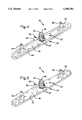
- FIG. 4 is a perspective view of the bottom of the plastic wash arm with the metal cover of FIG. 3;
- FIG. 5 is a perspective view, similar to FIG. 4, of the bottom of a second embodiment of the plastic wash arm with the metal cover.
- the dishwashing machine 10 generally includes a tub 12, a pump assembly 14, and a spray or wash arm assembly 16.
- the tub 12 which includes means such as racks (not shown) to receive dishes, silverware, glasses, and the like, defines a sump 18 at a lower portion thereof.
- the pump assembly 14, which is mounted to the tub 12 at a bottom of the sump 18, is powered by an electric motor 20 and is generally operable to pump wash water from the sump 18 to the wash arm assembly 16 when operating in a recirculating mode, and to pump wash water from the sump 18 to a drain (not shown) when operated in a drain mode. Streams of dish-cleaning wash water project upwardly from the wash arm assembly 16 to the dishes in the racks and then fall to the sump 18 at the bottom of the tub 12.
- the wash arm assembly 16 includes a plastic wash arm 22 and a metal cover 24.
- FIG. 2 illustrates the plastic wash arm 22 which includes first and second arm portions 26, 28 extending in opposite directions and a generally hollow interior.
- the plastic wash arm 22 is preferably molded in upper and lower halves 30, 32 from a thermoplastic material such as polypropylene.
- the upper and lower halves 30, 32 are subsequently joined together by a process such as ultrasonic welding or the like to form a water-tight joint and thereby create the one-piece plastic wash arm 22.
- the upper and lower halves 30, 32 are preferably joined at a generally horizontal plane intersecting the lateral surfaces 34 of the first and second arm portions 26, 28.
- a top surface 36 of the plastic wash arm 22 has an upwardly stepped portion 38 which is generally planar and extends across each of the arm portions 26, 28.
- the stepped portion 38 provides or defines a series of upwardly directed openings or wash jets 40, 42 through which the streams of dish-cleaning wash water project.
- the illustrated plastic wash arm 22 provides four circular wash jets 40 on the first arm portion 26 and three circular wash jets 40 on the second arm portion 28. Additionally, a generally crescent-shaped wash jet 42 is provided at the outer end of each of the arm members 26, 28.
- the wash jets 40, 42 are preferably adapted such that reaction forces are created by the water emanating from the wash jets 40, 42 to rotatably drive the wash arm assembly 16 about its axis of rotation 44. To achieve this result, some or all of the wash jets 40, 42 can be upwardly and outwardly directed.
- the wash jets 40, 42 are adapted such that the wash arm assembly 16 rotates at about 20-22 revolutions-per-minute.
- wash jets 40, 42 may be employed to supply sprays of wash water to the dishes within the tub 12.
- a generally planar bottom surface bottom surface 46 (FIG. 4) of the plastic wash arm 22 has a downwardly-directed cylindrical hub 48 at the intersection of the first and second arm portions 26, 28 which is generally coaxial with the vertical axis of rotation 44 of the wash arm assembly 16.
- the hub 48 includes a pair of resilient snap-fit clips 50 (FIG. 4) for mounting the wash arm assembly 16 to the pump assembly 14.
- the hub 48 forms an interior passage which communicates the hollow interior of the plastic wash arm 22 with an inlet 52 at a lower end of the hub 48. When the wash arm assembly 16 is mounted, the inlet 52 is in fluid communication with an outlet (not shown) of the pump assembly 14.
- the bottom surface 46 of the plastic wash arm 22 also provides downwardly directed, generally rectangularly-shaped, extensions 54, 56.
- Each of the extensions 54, 56 provide or define an opening or wash jet 58, 60 through which a stream of filter-cleaning wash water projects.
- An outer extension 54 is provided near the outer end of each of the arm portions 26, 28.
- Each outer extension 54 defines a wash jet 58 which provides an inwardly and generally horizontal stream of wash water.
- An inner extension 56 is provided near the hub 48 on the second arm portion 28.
- the inner extension 56 defines a wash jet 60 which provides an downwardly and generally vertical stream of wash water. Together, the clean-out wash jets 58, 60 operate to clean a filter at the inlet of the pump assembly 14.
- FIGS. 3 and 4 illustrate the wash arm assembly 16 with the metal cover 24 installed on the plastic wash arm 2.
- the one-piece metal cover 24 is preferably formed from stainless steel but other suitable metals can be alternatively utilized.
- the metal cover 24 wraps over the top surface 36 of the plastic wash arm 22, around the lateral surfaces 34 of the plastic wash arm 22, and over a portion of the bottom surface 46 of the plastic wash arm 22.
- the metal 24 cover substantially covers the entire top and lateral surfaces 36, 34 of the plastic wash arm 22.
- the portion of the metal cover 24 over the top surface 36 of the plastic wash arm 22 is generally planar and defines clearance openings 62 aligned with the wash jets 40, 42.
- the openings 62 are sized, shaped, and positioned such that the metal cover 24 does not interfere with the streams of wash water from the wash jets 40, 42.
- the metal cover 24 includes a generally continuous and inwardly directed flange 64 around the periphery of the bottom surface 46 of the plastic wash arm 22. The flange 64 engages the bottom surface 46 of the plastic wash arm 22 to retain the metal cover 24 on the plastic wash arm 22.
- the metal cover 24 is preferably formed to substantially conform to the shape of the plastic spray arm 24. To this end, the metal cover 24 can be stamped directly onto the molded plastic spray arm 22.
- FIG. 5 illustrates a metal cover 70 which is similar to the metal cover 24 of FIG. 4 except that the metal cover 70 is held onto the plastic wash arm 22 by a series of spaced apart inwardly extending tabs 72 at the bottom surface 46 of the plastic wash 22 arm rather than the generally continuous flange 64.
- FIG. 5 uses like reference numerals for like structure.
- the metal cover 70 illustrates that alternative means for attaching the metal cover 70 to the plastic spray arm 22 can be utilized.
Landscapes
- Washing And Drying Of Tableware (AREA)
Abstract
The present invention provides a wash arm assembly for a dishwasher which includes a molded plastic wash arm and a stainless steel cover. The plastic wash arm has a top surface, lateral surfaces, and a bottom surface and the stainless steel cover wraps over the top surface of the plastic wash arm, around the lateral surfaces of the plastic wash arm, and over a portion of the bottom surface of the plastic spray arm to hold the cover on the spray arm. The top surface of the plastic wash arm defines a series of wash jets and the stainless steel cover defines openings aligned with the wash jets so that the metal cover does not interfere with the wash jets.
Description
1. Field of the Invention
The present invention generally relates to a rotatable wash arm for a dishwasher and, more particularly, to an improved wash arm assembly which includes a plastic wash arm and a metal cover.
2. Description of Related Art
Automatic dishwashers which pump wash water through rotatable wash arms for distribution of the wash water throughout the washing chamber, to wash articles placed therein, have traditionally utilized wash arms manufactured from stainless steel material. Stainless steel wash arms, however, can require a large number of parts and therefore a large amount of manufacturing tooling and assembly. This is especially true when the wash arm includes extensions such as, for example, extensions for clean-out jets for cleaning a filter at a pump inlet. As a result, wash arms are often manufactured from a thermoplastic material in order to realize a reduction in manufacturing costs. Thermoplastic wash arms, however, have a different appearance than the traditional stainless steel wash arms and may not have a pleasing aesthetic appearance to the operator of the dishwasher. Accordingly there is a need in the art for an improved wash arm which provides a pleasing aesthetic appearance at a reduced manufacturing cost.
The present invention provides an improved wash arm assembly for a dishwasher which overcomes at least some of the above-described problems. The wash arm assembly includes a plastic wash arm and a metal cover. The plastic wash arm has a top surface, lateral surfaces, and a bottom surface and the metal cover wraps over the top surface and around the lateral surfaces of the plastic wash arm. In preferred embodiments, the metal cover extends over a portion of the bottom surface to hold the metal cover on the plastic wash arm. The metal cover provides a pleasing aesthetic appearance to the wash arm at a reduced cost.
These and further features of the present invention will be apparent with reference to the following description and drawings, wherein:
FIG. 1 is a perspective view of a dishwasher according to the present invention with items removed for clarity;
FIG. 2. is a perspective view of the top of a plastic wash arm;
FIG. 3 is a perspective view of the top of the plastic wash arm of FIG. 2 with a metal cover according to the present invention;
FIG. 4 is a perspective view of the bottom of the plastic wash arm with the metal cover of FIG. 3; and
FIG. 5 is a perspective view, similar to FIG. 4, of the bottom of a second embodiment of the plastic wash arm with the metal cover.
With reference to the drawing figures, components of a dishwashing machine 10 in accordance with the present invention are shown. The dishwashing machine 10 generally includes a tub 12, a pump assembly 14, and a spray or wash arm assembly 16. The tub 12, which includes means such as racks (not shown) to receive dishes, silverware, glasses, and the like, defines a sump 18 at a lower portion thereof. The pump assembly 14, which is mounted to the tub 12 at a bottom of the sump 18, is powered by an electric motor 20 and is generally operable to pump wash water from the sump 18 to the wash arm assembly 16 when operating in a recirculating mode, and to pump wash water from the sump 18 to a drain (not shown) when operated in a drain mode. Streams of dish-cleaning wash water project upwardly from the wash arm assembly 16 to the dishes in the racks and then fall to the sump 18 at the bottom of the tub 12. The wash arm assembly 16 includes a plastic wash arm 22 and a metal cover 24.
FIG. 2 illustrates the plastic wash arm 22 which includes first and second arm portions 26, 28 extending in opposite directions and a generally hollow interior. The plastic wash arm 22 is preferably molded in upper and lower halves 30, 32 from a thermoplastic material such as polypropylene. The upper and lower halves 30, 32 are subsequently joined together by a process such as ultrasonic welding or the like to form a water-tight joint and thereby create the one-piece plastic wash arm 22. The upper and lower halves 30, 32 are preferably joined at a generally horizontal plane intersecting the lateral surfaces 34 of the first and second arm portions 26, 28.
A top surface 36 of the plastic wash arm 22 has an upwardly stepped portion 38 which is generally planar and extends across each of the arm portions 26, 28. The stepped portion 38 provides or defines a series of upwardly directed openings or wash jets 40, 42 through which the streams of dish-cleaning wash water project. The illustrated plastic wash arm 22 provides four circular wash jets 40 on the first arm portion 26 and three circular wash jets 40 on the second arm portion 28. Additionally, a generally crescent-shaped wash jet 42 is provided at the outer end of each of the arm members 26, 28. The wash jets 40, 42 are preferably adapted such that reaction forces are created by the water emanating from the wash jets 40, 42 to rotatably drive the wash arm assembly 16 about its axis of rotation 44. To achieve this result, some or all of the wash jets 40, 42 can be upwardly and outwardly directed. Preferably, the wash jets 40, 42 are adapted such that the wash arm assembly 16 rotates at about 20-22 revolutions-per-minute.
Naturally, the scope of the present invention is not limited to the specific pattern, shape, number, or size of the wash jets 40, 42 described herein. Rather, it is evident that any type or arrangement of wash jets 40, 42 may be employed to supply sprays of wash water to the dishes within the tub 12.
A generally planar bottom surface bottom surface 46 (FIG. 4) of the plastic wash arm 22 has a downwardly-directed cylindrical hub 48 at the intersection of the first and second arm portions 26, 28 which is generally coaxial with the vertical axis of rotation 44 of the wash arm assembly 16. The hub 48 includes a pair of resilient snap-fit clips 50 (FIG. 4) for mounting the wash arm assembly 16 to the pump assembly 14. The hub 48 forms an interior passage which communicates the hollow interior of the plastic wash arm 22 with an inlet 52 at a lower end of the hub 48. When the wash arm assembly 16 is mounted, the inlet 52 is in fluid communication with an outlet (not shown) of the pump assembly 14.
The bottom surface 46 of the plastic wash arm 22 also provides downwardly directed, generally rectangularly-shaped, extensions 54, 56. Each of the extensions 54, 56 provide or define an opening or wash jet 58, 60 through which a stream of filter-cleaning wash water projects. An outer extension 54 is provided near the outer end of each of the arm portions 26, 28. Each outer extension 54 defines a wash jet 58 which provides an inwardly and generally horizontal stream of wash water. An inner extension 56 is provided near the hub 48 on the second arm portion 28. The inner extension 56 defines a wash jet 60 which provides an downwardly and generally vertical stream of wash water. Together, the clean-out wash jets 58, 60 operate to clean a filter at the inlet of the pump assembly 14.
FIGS. 3 and 4 illustrate the wash arm assembly 16 with the metal cover 24 installed on the plastic wash arm 2. The one-piece metal cover 24 is preferably formed from stainless steel but other suitable metals can be alternatively utilized. The metal cover 24 wraps over the top surface 36 of the plastic wash arm 22, around the lateral surfaces 34 of the plastic wash arm 22, and over a portion of the bottom surface 46 of the plastic wash arm 22. As best shown in FIG. 3, the metal 24 cover substantially covers the entire top and lateral surfaces 36, 34 of the plastic wash arm 22. The portion of the metal cover 24 over the top surface 36 of the plastic wash arm 22 is generally planar and defines clearance openings 62 aligned with the wash jets 40, 42. The openings 62 are sized, shaped, and positioned such that the metal cover 24 does not interfere with the streams of wash water from the wash jets 40, 42. The metal cover 24 includes a generally continuous and inwardly directed flange 64 around the periphery of the bottom surface 46 of the plastic wash arm 22. The flange 64 engages the bottom surface 46 of the plastic wash arm 22 to retain the metal cover 24 on the plastic wash arm 22. The metal cover 24 is preferably formed to substantially conform to the shape of the plastic spray arm 24. To this end, the metal cover 24 can be stamped directly onto the molded plastic spray arm 22.
FIG. 5 illustrates a metal cover 70 which is similar to the metal cover 24 of FIG. 4 except that the metal cover 70 is held onto the plastic wash arm 22 by a series of spaced apart inwardly extending tabs 72 at the bottom surface 46 of the plastic wash 22 arm rather than the generally continuous flange 64. FIG. 5 uses like reference numerals for like structure. The metal cover 70 illustrates that alternative means for attaching the metal cover 70 to the plastic spray arm 22 can be utilized.
It is noted that while the illustrated embodiments describe in detail a lower wash arm assembly 16, the present invention can also be utilized with upper or intermediate wash arm assemblies. With upper or intermediate wash arm assemblies, however, it may be desirable to form the metal cover 24 such that the metal cover 24 is also over substantially the entire bottom surface 46 of the plastic wash arm 22.
Although particular embodiments of the invention have been described in detail, it will be understood that the invention is not limited correspondingly in scope, but includes all changes and modifications coming within the spirit and terms of the claims appended hereto.
Claims (9)
1. A dishwasher comprising:
a tub adapted to receive dishes to be washed and providing a sump to temporarily retain a quantity of water;
a pump assembly for circulating wash water from said sump throughout the tub;
a wash arm assembly rotatably mounted within said tub having a generally vertical axis of rotation, said wash arm assembly being generally hollow and receiving a portion of the wash water circulated by the pump assembly, said wash arm assembly including a plastic wash arm having a top surface, lateral surfaces, and a bottom surface, and a metal cover wrapping over said top surface and around said lateral surfaces of said plastic wash arm.
2. The dishwasher according to claim 1, wherein said top surface of said plastic wash arm defines a series of wash jets and said metal cover defines openings aligned with said wash jets.
3. The dishwasher according to claim 1, wherein said metal cover comprises stainless steel.
4. The dishwasher according to claim 1, wherein said metal cover wraps over at least a portion of said bottom surface of said plastic wash arm.
5. The dishwasher according to claim 1, wherein said metal cover includes a generally continuous flange at said bottom surface of said plastic wash arm.
6. The dishwasher according to claim 1, wherein said metal cover includes a series of spaced apart tabs at said bottom surface of said plastic wash arm.
7. The dishwasher to claim 1, wherein said metal cover is formed to substantially conform to a shape of said plastic wash arm.
8. The dishwasher according to claim 1, wherein said metal covers substantially all of said top surface and said lateral surfaces of said plastic wash arm assembly.
9. The dishwasher according to claim 1, wherein said plastic wash arm includes at least one extension downwardly extending from said bottom surface.
Priority Applications (3)
| Application Number | Priority Date | Filing Date | Title |
|---|---|---|---|
| US08/536,090 US5560381A (en) | 1995-09-29 | 1995-09-29 | Stainless steel cover for plastic spray arm |
| CA002180069A CA2180069A1 (en) | 1995-09-29 | 1996-06-27 | Stainless steel cover for plastic spray arm |
| EP96111664A EP0765629A1 (en) | 1995-09-29 | 1996-07-19 | Stainless steel cover for plastic spray arm |
Applications Claiming Priority (1)
| Application Number | Priority Date | Filing Date | Title |
|---|---|---|---|
| US08/536,090 US5560381A (en) | 1995-09-29 | 1995-09-29 | Stainless steel cover for plastic spray arm |
Publications (1)
| Publication Number | Publication Date |
|---|---|
| US5560381A true US5560381A (en) | 1996-10-01 |
Family
ID=24137102
Family Applications (1)
| Application Number | Title | Priority Date | Filing Date |
|---|---|---|---|
| US08/536,090 Expired - Fee Related US5560381A (en) | 1995-09-29 | 1995-09-29 | Stainless steel cover for plastic spray arm |
Country Status (3)
| Country | Link |
|---|---|
| US (1) | US5560381A (en) |
| EP (1) | EP0765629A1 (en) |
| CA (1) | CA2180069A1 (en) |
Cited By (11)
| Publication number | Priority date | Publication date | Assignee | Title |
|---|---|---|---|---|
| WO2001083922A1 (en) | 2000-04-28 | 2001-11-08 | Wherehouse Entertainment, Inc. | Theft-resistant releasable container for valuable articles |
| US20060086378A1 (en) * | 2004-10-27 | 2006-04-27 | Meissner Kenneth R | Carboy support bracket and method of using same |
| US20060086379A1 (en) * | 2004-10-26 | 2006-04-27 | Maytag Corporation | Flame treatment of washing machine parts |
| US20060162747A1 (en) * | 2005-01-25 | 2006-07-27 | Mike Belleville | Polypro scrap accumulator |
| EP1925249A1 (en) * | 2006-11-24 | 2008-05-28 | Electrolux Home Products Corporation N.V. | Water dispensing component of a household appliance |
| US20090032066A1 (en) * | 2006-02-16 | 2009-02-05 | BSH Bosch und Siemens Hausgeräte GmbH | Dishwasher With Spray Apparatus |
| US20090159101A1 (en) * | 2007-12-21 | 2009-06-25 | Wolf Appliance, Inc. | Fluid supply system for appliance |
| CN104138247A (en) * | 2014-07-15 | 2014-11-12 | 湖州南佳厨房设备有限公司 | High-pressure spray device for small-sized bowl washing machine |
| USD900417S1 (en) * | 2013-10-29 | 2020-10-27 | Whirlpool Corporation | Sprayer for dish washing machine |
| USD937506S1 (en) * | 2019-10-04 | 2021-11-30 | Whirlpool Corporation | Sprayer assembly |
| USD967571S1 (en) * | 2020-12-17 | 2022-10-18 | Midea Group Co., Ltd. | Spray arm for dishwasher |
Citations (21)
| Publication number | Priority date | Publication date | Assignee | Title |
|---|---|---|---|---|
| US2905393A (en) * | 1958-03-14 | 1959-09-22 | George J Federighi | Rotary spray arm for a cleaning machine |
| US3292645A (en) * | 1964-10-13 | 1966-12-20 | Gen Motors Corp | Reaction spray dishwasher having an improved water fill system |
| US3334750A (en) * | 1963-05-31 | 1967-08-08 | Mullins Mfg Corp | Dishwasher strainer with alternate filtering positions |
| US3348775A (en) * | 1965-10-22 | 1967-10-24 | Gen Motors Corp | Reaction jet spray arm for dishwashers having simultaneous rotation about perpendicular axis |
| US3669132A (en) * | 1970-09-29 | 1972-06-13 | Wesley Mamrose | Dishwashing apparatus |
| US3941139A (en) * | 1974-08-15 | 1976-03-02 | Whirlpool Corporation | Dishwasher spray assembly with intermittently operating nozzles |
| US3949772A (en) * | 1974-12-13 | 1976-04-13 | General Electric Company | Door type dishwasher |
| US4064887A (en) * | 1976-07-27 | 1977-12-27 | Hobart Corporation | Upper level wash arm system |
| US4227546A (en) * | 1978-09-06 | 1980-10-14 | The Maytag Company | Dishwasher fluid control system |
| FR2505643A1 (en) * | 1981-05-14 | 1982-11-19 | Candy Ind Spa | Dishwashing machine with alternate zones for washing - uses valve in pump outlet to direct water to upper or lower sprays or simultaneously to both |
| US4387496A (en) * | 1980-12-08 | 1983-06-14 | Whirlpool Corporation | Method of forming a spray arm |
| US4416300A (en) * | 1981-09-25 | 1983-11-22 | The Maytag Company | Heat shielded thermoplastic wash arm for dishwasher |
| US4509687A (en) * | 1983-07-20 | 1985-04-09 | General Electric Company | Multiple spray distribution system for a domestic dishwasher |
| GB2199734A (en) * | 1986-12-11 | 1988-07-20 | Zanussi A Spa Industrie | Dishwasher with rotary spray arm having means for selectively altering spray direction |
| GB2200535A (en) * | 1987-01-30 | 1988-08-10 | Bosch Siemens Hausgeraete | Crockery basket for a front-loading dishwashing machine |
| GB2204482A (en) * | 1987-04-08 | 1988-11-16 | Zanussi A Spa Industrie | Dishwashing machine with filter cleaning arrangement |
| US4991611A (en) * | 1989-06-08 | 1991-02-12 | Whirlpool Corporation | Lower spray arm for dishwasher |
| DE4036930A1 (en) * | 1990-11-20 | 1992-05-21 | Miele & Cie | Rotatable spray arm for electric dishwasher - is fitted with two different spray jet openings on either side of rotation axis |
| US5267582A (en) * | 1992-01-21 | 1993-12-07 | Maytag Corporation | Wash arm construction |
| US5320120A (en) * | 1993-06-17 | 1994-06-14 | General Electric Company | Dishwasher with dual pumps |
| US5333631A (en) * | 1993-05-04 | 1994-08-02 | White Consolidated Industries, Inc. | Cleaning wash-arm for dishwashing filter |
Family Cites Families (2)
| Publication number | Priority date | Publication date | Assignee | Title |
|---|---|---|---|---|
| DE7831102U1 (en) * | 1978-10-19 | 1979-02-08 | Licentia Patent-Verwaltungs-Gmbh, 6000 Frankfurt | DISHWASHER |
| DE8702312U1 (en) * | 1987-02-14 | 1988-06-23 | Licentia Patent-Verwaltungs-Gmbh, 6000 Frankfurt | Dishwasher with one spray arm |
-
1995
- 1995-09-29 US US08/536,090 patent/US5560381A/en not_active Expired - Fee Related
-
1996
- 1996-06-27 CA CA002180069A patent/CA2180069A1/en not_active Abandoned
- 1996-07-19 EP EP96111664A patent/EP0765629A1/en not_active Withdrawn
Patent Citations (21)
| Publication number | Priority date | Publication date | Assignee | Title |
|---|---|---|---|---|
| US2905393A (en) * | 1958-03-14 | 1959-09-22 | George J Federighi | Rotary spray arm for a cleaning machine |
| US3334750A (en) * | 1963-05-31 | 1967-08-08 | Mullins Mfg Corp | Dishwasher strainer with alternate filtering positions |
| US3292645A (en) * | 1964-10-13 | 1966-12-20 | Gen Motors Corp | Reaction spray dishwasher having an improved water fill system |
| US3348775A (en) * | 1965-10-22 | 1967-10-24 | Gen Motors Corp | Reaction jet spray arm for dishwashers having simultaneous rotation about perpendicular axis |
| US3669132A (en) * | 1970-09-29 | 1972-06-13 | Wesley Mamrose | Dishwashing apparatus |
| US3941139A (en) * | 1974-08-15 | 1976-03-02 | Whirlpool Corporation | Dishwasher spray assembly with intermittently operating nozzles |
| US3949772A (en) * | 1974-12-13 | 1976-04-13 | General Electric Company | Door type dishwasher |
| US4064887A (en) * | 1976-07-27 | 1977-12-27 | Hobart Corporation | Upper level wash arm system |
| US4227546A (en) * | 1978-09-06 | 1980-10-14 | The Maytag Company | Dishwasher fluid control system |
| US4387496A (en) * | 1980-12-08 | 1983-06-14 | Whirlpool Corporation | Method of forming a spray arm |
| FR2505643A1 (en) * | 1981-05-14 | 1982-11-19 | Candy Ind Spa | Dishwashing machine with alternate zones for washing - uses valve in pump outlet to direct water to upper or lower sprays or simultaneously to both |
| US4416300A (en) * | 1981-09-25 | 1983-11-22 | The Maytag Company | Heat shielded thermoplastic wash arm for dishwasher |
| US4509687A (en) * | 1983-07-20 | 1985-04-09 | General Electric Company | Multiple spray distribution system for a domestic dishwasher |
| GB2199734A (en) * | 1986-12-11 | 1988-07-20 | Zanussi A Spa Industrie | Dishwasher with rotary spray arm having means for selectively altering spray direction |
| GB2200535A (en) * | 1987-01-30 | 1988-08-10 | Bosch Siemens Hausgeraete | Crockery basket for a front-loading dishwashing machine |
| GB2204482A (en) * | 1987-04-08 | 1988-11-16 | Zanussi A Spa Industrie | Dishwashing machine with filter cleaning arrangement |
| US4991611A (en) * | 1989-06-08 | 1991-02-12 | Whirlpool Corporation | Lower spray arm for dishwasher |
| DE4036930A1 (en) * | 1990-11-20 | 1992-05-21 | Miele & Cie | Rotatable spray arm for electric dishwasher - is fitted with two different spray jet openings on either side of rotation axis |
| US5267582A (en) * | 1992-01-21 | 1993-12-07 | Maytag Corporation | Wash arm construction |
| US5333631A (en) * | 1993-05-04 | 1994-08-02 | White Consolidated Industries, Inc. | Cleaning wash-arm for dishwashing filter |
| US5320120A (en) * | 1993-06-17 | 1994-06-14 | General Electric Company | Dishwasher with dual pumps |
Cited By (18)
| Publication number | Priority date | Publication date | Assignee | Title |
|---|---|---|---|---|
| WO2001083922A1 (en) | 2000-04-28 | 2001-11-08 | Wherehouse Entertainment, Inc. | Theft-resistant releasable container for valuable articles |
| US20060086379A1 (en) * | 2004-10-26 | 2006-04-27 | Maytag Corporation | Flame treatment of washing machine parts |
| US20060086378A1 (en) * | 2004-10-27 | 2006-04-27 | Meissner Kenneth R | Carboy support bracket and method of using same |
| US7455068B2 (en) * | 2004-10-27 | 2008-11-25 | Kenneth Roy Meissner | Carboy support bracket and method of using same |
| US20060162747A1 (en) * | 2005-01-25 | 2006-07-27 | Mike Belleville | Polypro scrap accumulator |
| US8221558B2 (en) * | 2006-02-16 | 2012-07-17 | Bsh Bosch Und Siemens Hausgeraete Gmbh | Dishwasher with spray apparatus |
| US20090032066A1 (en) * | 2006-02-16 | 2009-02-05 | BSH Bosch und Siemens Hausgeräte GmbH | Dishwasher With Spray Apparatus |
| EP1986539B2 (en) † | 2006-02-16 | 2019-05-01 | BSH Hausgeräte GmbH | Dishwasher with spray apparatus |
| EP1925249A1 (en) * | 2006-11-24 | 2008-05-28 | Electrolux Home Products Corporation N.V. | Water dispensing component of a household appliance |
| US8166983B2 (en) | 2007-12-21 | 2012-05-01 | Wolf Appliance, Inc. | Fluid supply system for appliance |
| US20090159101A1 (en) * | 2007-12-21 | 2009-06-25 | Wolf Appliance, Inc. | Fluid supply system for appliance |
| USD900417S1 (en) * | 2013-10-29 | 2020-10-27 | Whirlpool Corporation | Sprayer for dish washing machine |
| USD927101S1 (en) | 2013-10-29 | 2021-08-03 | Whirlpool Corporation | Sprayer for dish washing machine |
| USD955671S1 (en) | 2013-10-29 | 2022-06-21 | Whirlpool Corporation | Sprayer for dish washing machine |
| CN104138247A (en) * | 2014-07-15 | 2014-11-12 | 湖州南佳厨房设备有限公司 | High-pressure spray device for small-sized bowl washing machine |
| CN104138247B (en) * | 2014-07-15 | 2017-01-11 | 湖州南佳厨房设备有限公司 | High-pressure spray device for small-sized bowl washing machine |
| USD937506S1 (en) * | 2019-10-04 | 2021-11-30 | Whirlpool Corporation | Sprayer assembly |
| USD967571S1 (en) * | 2020-12-17 | 2022-10-18 | Midea Group Co., Ltd. | Spray arm for dishwasher |
Also Published As
| Publication number | Publication date |
|---|---|
| EP0765629A1 (en) | 1997-04-02 |
| CA2180069A1 (en) | 1997-03-30 |
Similar Documents
| Publication | Publication Date | Title |
|---|---|---|
| US5560381A (en) | Stainless steel cover for plastic spray arm | |
| US6871653B2 (en) | Method for cleaning an in-sink dishwasher | |
| US5333631A (en) | Cleaning wash-arm for dishwashing filter | |
| US20080163904A1 (en) | Nozzle Structure of Dish Washer | |
| GB2314009A (en) | Dispersing washing water of a dishwasher | |
| US3915182A (en) | Spray deflector for dishwashers | |
| KR101138883B1 (en) | A dish washing machine | |
| CA2936431A1 (en) | Rotary spray arm for a washing device and application thereof | |
| US3961984A (en) | Space saver dishwasher | |
| US10499788B2 (en) | Dishwasher with pump hangar to reduce motor noise | |
| CN114343535A (en) | Cleaning machine | |
| US5954073A (en) | Wash apparatus for a dishwasher | |
| US20180098680A1 (en) | Spray arm assembly for dishwasher appliance | |
| US9179818B2 (en) | Spray arm assembly for a dishwasher appliance | |
| US11672402B2 (en) | Blade and pump impeller assembly for a dishwasher | |
| CN217429935U (en) | Cleaning machine | |
| US10512387B2 (en) | Hydraulically actuated diverter for an appliance | |
| CN210582416U (en) | Spray arm device and dish-washing machine | |
| CN209285408U (en) | A kind of covering plate structure of water tank cleaner | |
| CN209826614U (en) | Dish washing machine | |
| CN209932633U (en) | Spraying system installed on cleaning machine and cleaning machine | |
| CN216984830U (en) | Cleaning machine | |
| KR900007534Y1 (en) | A water-scattering device in dish washing machine | |
| KR0176673B1 (en) | Dishwasher with top nozzle | |
| CN110876597A (en) | Cover plate structure of water tank type cleaning machine |
Legal Events
| Date | Code | Title | Description |
|---|---|---|---|
| AS | Assignment |
Owner name: WHITE CONSOLIDATED INDUSTRIES, INC., OHIO Free format text: ASSIGNMENT OF ASSIGNORS INTEREST;ASSIGNOR:EDWARDS, JAMES MICHAEL;REEL/FRAME:007705/0855 Effective date: 19950921 |
|
| FEPP | Fee payment procedure |
Free format text: PAYOR NUMBER ASSIGNED (ORIGINAL EVENT CODE: ASPN); ENTITY STATUS OF PATENT OWNER: LARGE ENTITY |
|
| REMI | Maintenance fee reminder mailed | ||
| LAPS | Lapse for failure to pay maintenance fees | ||
| FP | Lapsed due to failure to pay maintenance fee |
Effective date: 20001001 |
|
| STCH | Information on status: patent discontinuation |
Free format text: PATENT EXPIRED DUE TO NONPAYMENT OF MAINTENANCE FEES UNDER 37 CFR 1.362 |