US5527231A - Method for controlling a continuously variable transmission of a motor vehicle - Google Patents
Method for controlling a continuously variable transmission of a motor vehicle Download PDFInfo
- Publication number
- US5527231A US5527231A US08/170,182 US17018294A US5527231A US 5527231 A US5527231 A US 5527231A US 17018294 A US17018294 A US 17018294A US 5527231 A US5527231 A US 5527231A
- Authority
- US
- United States
- Prior art keywords
- transmission ratio
- nmot
- speed
- acceleration
- transverse
- Prior art date
- Legal status (The legal status is an assumption and is not a legal conclusion. Google has not performed a legal analysis and makes no representation as to the accuracy of the status listed.)
- Expired - Lifetime
Links
- 230000005540 biological transmission Effects 0.000 title claims abstract description 171
- 238000000034 method Methods 0.000 title claims abstract description 43
- 230000000694 effects Effects 0.000 claims abstract description 28
- 238000002485 combustion reaction Methods 0.000 claims abstract description 13
- 230000001133 acceleration Effects 0.000 claims description 37
- 238000010586 diagram Methods 0.000 claims description 18
- 230000008859 change Effects 0.000 claims description 14
- 230000007423 decrease Effects 0.000 claims description 4
- 230000002829 reductive effect Effects 0.000 claims description 4
- 238000005096 rolling process Methods 0.000 claims description 3
- 230000003247 decreasing effect Effects 0.000 claims description 2
- 230000000717 retained effect Effects 0.000 claims description 2
- 230000014759 maintenance of location Effects 0.000 abstract description 10
- 230000007246 mechanism Effects 0.000 abstract description 10
- 230000006870 function Effects 0.000 description 10
- 230000009467 reduction Effects 0.000 description 6
- 101100374156 Arabidopsis thaliana RKL1 gene Proteins 0.000 description 5
- 230000009471 action Effects 0.000 description 4
- 230000001419 dependent effect Effects 0.000 description 4
- 230000004044 response Effects 0.000 description 4
- 238000013459 approach Methods 0.000 description 3
- 238000012544 monitoring process Methods 0.000 description 3
- XDDAORKBJWWYJS-UHFFFAOYSA-N glyphosate Chemical group OC(=O)CNCP(O)(O)=O XDDAORKBJWWYJS-UHFFFAOYSA-N 0.000 description 2
- 230000007774 longterm Effects 0.000 description 2
- 230000008569 process Effects 0.000 description 2
- 239000013589 supplement Substances 0.000 description 2
- 238000012360 testing method Methods 0.000 description 2
- 230000004913 activation Effects 0.000 description 1
- 230000006978 adaptation Effects 0.000 description 1
- 239000000853 adhesive Substances 0.000 description 1
- 230000001070 adhesive effect Effects 0.000 description 1
- 230000008901 benefit Effects 0.000 description 1
- 230000008878 coupling Effects 0.000 description 1
- 238000010168 coupling process Methods 0.000 description 1
- 238000005859 coupling reaction Methods 0.000 description 1
- 238000013461 design Methods 0.000 description 1
- 238000011161 development Methods 0.000 description 1
- 238000013213 extrapolation Methods 0.000 description 1
- 239000012530 fluid Substances 0.000 description 1
- 230000005484 gravity Effects 0.000 description 1
- 238000002347 injection Methods 0.000 description 1
- 239000007924 injection Substances 0.000 description 1
- 230000000670 limiting effect Effects 0.000 description 1
- 238000005259 measurement Methods 0.000 description 1
- 230000007935 neutral effect Effects 0.000 description 1
- 239000000047 product Substances 0.000 description 1
- 230000000750 progressive effect Effects 0.000 description 1
- 230000001373 regressive effect Effects 0.000 description 1
- 230000002441 reversible effect Effects 0.000 description 1
- 230000007704 transition Effects 0.000 description 1
Images


Classifications
-
- F—MECHANICAL ENGINEERING; LIGHTING; HEATING; WEAPONS; BLASTING
- F16—ENGINEERING ELEMENTS AND UNITS; GENERAL MEASURES FOR PRODUCING AND MAINTAINING EFFECTIVE FUNCTIONING OF MACHINES OR INSTALLATIONS; THERMAL INSULATION IN GENERAL
- F16H—GEARING
- F16H61/00—Control functions within control units of change-speed- or reversing-gearings for conveying rotary motion ; Control of exclusively fluid gearing, friction gearing, gearings with endless flexible members or other particular types of gearing
- F16H61/66—Control functions within control units of change-speed- or reversing-gearings for conveying rotary motion ; Control of exclusively fluid gearing, friction gearing, gearings with endless flexible members or other particular types of gearing specially adapted for continuously variable gearings
- F16H61/662—Control functions within control units of change-speed- or reversing-gearings for conveying rotary motion ; Control of exclusively fluid gearing, friction gearing, gearings with endless flexible members or other particular types of gearing specially adapted for continuously variable gearings with endless flexible members
- F16H61/66254—Control functions within control units of change-speed- or reversing-gearings for conveying rotary motion ; Control of exclusively fluid gearing, friction gearing, gearings with endless flexible members or other particular types of gearing specially adapted for continuously variable gearings with endless flexible members controlling of shifting being influenced by a signal derived from the engine and the main coupling
- F16H61/66259—Control functions within control units of change-speed- or reversing-gearings for conveying rotary motion ; Control of exclusively fluid gearing, friction gearing, gearings with endless flexible members or other particular types of gearing specially adapted for continuously variable gearings with endless flexible members controlling of shifting being influenced by a signal derived from the engine and the main coupling using electrical or electronical sensing or control means
-
- B—PERFORMING OPERATIONS; TRANSPORTING
- B60—VEHICLES IN GENERAL
- B60W—CONJOINT CONTROL OF VEHICLE SUB-UNITS OF DIFFERENT TYPE OR DIFFERENT FUNCTION; CONTROL SYSTEMS SPECIALLY ADAPTED FOR HYBRID VEHICLES; ROAD VEHICLE DRIVE CONTROL SYSTEMS FOR PURPOSES NOT RELATED TO THE CONTROL OF A PARTICULAR SUB-UNIT
- B60W10/00—Conjoint control of vehicle sub-units of different type or different function
- B60W10/10—Conjoint control of vehicle sub-units of different type or different function including control of change-speed gearings
-
- B—PERFORMING OPERATIONS; TRANSPORTING
- B60—VEHICLES IN GENERAL
- B60W—CONJOINT CONTROL OF VEHICLE SUB-UNITS OF DIFFERENT TYPE OR DIFFERENT FUNCTION; CONTROL SYSTEMS SPECIALLY ADAPTED FOR HYBRID VEHICLES; ROAD VEHICLE DRIVE CONTROL SYSTEMS FOR PURPOSES NOT RELATED TO THE CONTROL OF A PARTICULAR SUB-UNIT
- B60W10/00—Conjoint control of vehicle sub-units of different type or different function
- B60W10/18—Conjoint control of vehicle sub-units of different type or different function including control of braking systems
-
- B—PERFORMING OPERATIONS; TRANSPORTING
- B60—VEHICLES IN GENERAL
- B60W—CONJOINT CONTROL OF VEHICLE SUB-UNITS OF DIFFERENT TYPE OR DIFFERENT FUNCTION; CONTROL SYSTEMS SPECIALLY ADAPTED FOR HYBRID VEHICLES; ROAD VEHICLE DRIVE CONTROL SYSTEMS FOR PURPOSES NOT RELATED TO THE CONTROL OF A PARTICULAR SUB-UNIT
- B60W30/00—Purposes of road vehicle drive control systems not related to the control of a particular sub-unit, e.g. of systems using conjoint control of vehicle sub-units
- B60W30/18—Propelling the vehicle
- B60W30/1819—Propulsion control with control means using analogue circuits, relays or mechanical links
-
- F—MECHANICAL ENGINEERING; LIGHTING; HEATING; WEAPONS; BLASTING
- F16—ENGINEERING ELEMENTS AND UNITS; GENERAL MEASURES FOR PRODUCING AND MAINTAINING EFFECTIVE FUNCTIONING OF MACHINES OR INSTALLATIONS; THERMAL INSULATION IN GENERAL
- F16H—GEARING
- F16H61/00—Control functions within control units of change-speed- or reversing-gearings for conveying rotary motion ; Control of exclusively fluid gearing, friction gearing, gearings with endless flexible members or other particular types of gearing
- F16H61/21—Providing engine brake control
-
- B—PERFORMING OPERATIONS; TRANSPORTING
- B60—VEHICLES IN GENERAL
- B60W—CONJOINT CONTROL OF VEHICLE SUB-UNITS OF DIFFERENT TYPE OR DIFFERENT FUNCTION; CONTROL SYSTEMS SPECIALLY ADAPTED FOR HYBRID VEHICLES; ROAD VEHICLE DRIVE CONTROL SYSTEMS FOR PURPOSES NOT RELATED TO THE CONTROL OF A PARTICULAR SUB-UNIT
- B60W2520/00—Input parameters relating to overall vehicle dynamics
- B60W2520/12—Lateral speed
- B60W2520/125—Lateral acceleration
-
- F—MECHANICAL ENGINEERING; LIGHTING; HEATING; WEAPONS; BLASTING
- F16—ENGINEERING ELEMENTS AND UNITS; GENERAL MEASURES FOR PRODUCING AND MAINTAINING EFFECTIVE FUNCTIONING OF MACHINES OR INSTALLATIONS; THERMAL INSULATION IN GENERAL
- F16H—GEARING
- F16H59/00—Control inputs to control units of change-speed-, or reversing-gearings for conveying rotary motion
- F16H59/14—Inputs being a function of torque or torque demand
- F16H59/18—Inputs being a function of torque or torque demand dependent on the position of the accelerator pedal
- F16H2059/186—Coasting
-
- F—MECHANICAL ENGINEERING; LIGHTING; HEATING; WEAPONS; BLASTING
- F16—ENGINEERING ELEMENTS AND UNITS; GENERAL MEASURES FOR PRODUCING AND MAINTAINING EFFECTIVE FUNCTIONING OF MACHINES OR INSTALLATIONS; THERMAL INSULATION IN GENERAL
- F16H—GEARING
- F16H61/00—Control functions within control units of change-speed- or reversing-gearings for conveying rotary motion ; Control of exclusively fluid gearing, friction gearing, gearings with endless flexible members or other particular types of gearing
- F16H61/02—Control functions within control units of change-speed- or reversing-gearings for conveying rotary motion ; Control of exclusively fluid gearing, friction gearing, gearings with endless flexible members or other particular types of gearing characterised by the signals used
- F16H61/0202—Control functions within control units of change-speed- or reversing-gearings for conveying rotary motion ; Control of exclusively fluid gearing, friction gearing, gearings with endless flexible members or other particular types of gearing characterised by the signals used the signals being electric
- F16H61/0204—Control functions within control units of change-speed- or reversing-gearings for conveying rotary motion ; Control of exclusively fluid gearing, friction gearing, gearings with endless flexible members or other particular types of gearing characterised by the signals used the signals being electric for gearshift control, e.g. control functions for performing shifting or generation of shift signal
- F16H61/0213—Control functions within control units of change-speed- or reversing-gearings for conveying rotary motion ; Control of exclusively fluid gearing, friction gearing, gearings with endless flexible members or other particular types of gearing characterised by the signals used the signals being electric for gearshift control, e.g. control functions for performing shifting or generation of shift signal characterised by the method for generating shift signals
- F16H2061/0234—Adapting the ratios to special vehicle conditions
- F16H2061/0237—Selecting ratios for providing engine braking
-
- F—MECHANICAL ENGINEERING; LIGHTING; HEATING; WEAPONS; BLASTING
- F16—ENGINEERING ELEMENTS AND UNITS; GENERAL MEASURES FOR PRODUCING AND MAINTAINING EFFECTIVE FUNCTIONING OF MACHINES OR INSTALLATIONS; THERMAL INSULATION IN GENERAL
- F16H—GEARING
- F16H59/00—Control inputs to control units of change-speed-, or reversing-gearings for conveying rotary motion
- F16H59/14—Inputs being a function of torque or torque demand
- F16H59/141—Inputs being a function of torque or torque demand of rate of change of torque or torque demand
-
- F—MECHANICAL ENGINEERING; LIGHTING; HEATING; WEAPONS; BLASTING
- F16—ENGINEERING ELEMENTS AND UNITS; GENERAL MEASURES FOR PRODUCING AND MAINTAINING EFFECTIVE FUNCTIONING OF MACHINES OR INSTALLATIONS; THERMAL INSULATION IN GENERAL
- F16H—GEARING
- F16H61/00—Control functions within control units of change-speed- or reversing-gearings for conveying rotary motion ; Control of exclusively fluid gearing, friction gearing, gearings with endless flexible members or other particular types of gearing
- F16H61/16—Inhibiting or initiating shift during unfavourable conditions, e.g. preventing forward reverse shift at high vehicle speed, preventing engine over speed
Definitions
- the invention relates to a method according for controlling a continuously variable transmission of a motor vehicle.
- German Patent document DE-33 41 652 C2 has disclosed that this reduction of the transmission ratio (upshiding) in curves can be avoided by sensing the transverse acceleration of the motor vehicle. However, this procedure can only avoid shifting in curves.
- the DE- 39 22 040 A1 corresponding to U.S. Pat. No. 5,025,689, discloses a method for controlling an automatically shifting transmission, according to which the rate of change of the gas pedal is sensed and, if this rate falls below the specified (negative) limit, a signal is generated to prevent upshifting, inasmuch as push-type operation is detected. Upshifting is then prevented, until pull-type operation resumes and a fixed amount of time has passed.
- German Patent document DE- 39 22 051 A1 corresonding to U.S. Pat. No. 5,157,609 additionally provides that this period of time be made dependent on another parameter (driving activity), from a combination of several operating or driving parameters, and which evaluates the driving style of a driver or the currently prevailing traffic situation.
- this object is achieved by a method for controlling a continuously variable transmission (2) , which is activated electro-hydraulically, of a motor vehicle driven with an internal combustion engine (4), which can be controlled by a power-control element, including one of a gas pedal and a throttle valve, such that the transmission ration (ue) of the transmission (2) is automatically adjusted through the intermediacy of at least one characteristic control curve (RKL j ) in dependence on the position of the power control element (alpha (t)) and the engine rpm (nmot (t)), the method comprising the step of:
- a) at least one of 1) a service brake of the motor vehicle is activated (brake signal b 1 and 2) the time derivative of the driving speed (dv(t)/dr) is less than a first negative longitudinal-acceleration limit value (albg (ue, nmot, t), albg(ue, nmot, t) ⁇ 0 (dv(t)/dt ⁇ albg(ue, nmot, t)); and
- a transverse acceleration (aq(t)), sensed by means of a transverse-acceleration sensor (16), falls below a first specific transverse-acceleration limit curve (aqgl(v(t))) (aq(t) ⁇ aqgl(v(t)));
- the driving speed (v(t)) is less than a driving-speed limit value (vg(ue, SK(t))), (v(t) ⁇ vg(ue, SK(t))).
- the advantages of the invention primarily are to be regarded as the circumstance that a method has been created to control a continuously variable motor-vehicle transmission, preferably operated electro-hydraulically, in which the way the transmission ratio is adjusted during braking, especially before curves, has been further improved.
- the transmission ratio is here increased during braking, at a final third speed, such that here, too, the speed of adjustment is less than the maximum speed of adjustment.
- Adherence to the conditions in this connection guarantees safe operation of the motor vehicle.
- the system monitors that the transverse acceleration is not too high, that the vehicle is not slowed down too much and that the driving speed is not too high, especially so as to avoid a loss of the longitudinal and lateral guiding forces of the wheels of the motor vehicle.
- the braking torque of the driving (internal combustion) engine can affect the drive wheels more strongly.
- An increase of the transmission ratio during braking preferably is initiated when a state of a transmission-ratio retention mechanism is active.
- the latter is activated in well-known fashion when the motor vehicle approaches a curve and the driver no longer presses on the gas pedal.
- FIG. 1 shows a block circuit diagram of an electro-hydraulic control for a continuously variable transmission of a motor vehicle.
- FIG. 2 shows a family of several control curves, which associate specific theoretical engine rpm values with values of the throttle valve position.
- FIG. 3 shows a limiting curve to detect pull-type/push-type operation.
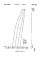
- FIG. 4 shows a first and second limit curve for transverse acceleration, as a function of the driving speed.
- FIG. 5 shows a characteristic diagram for a characteristic diagram parameter, which depends on the engine rpm and on the transmission ratio.
- FIG. 6 shows a characteristic diagram for a factor, which depends on the transmission ratio and on the driver activity.
- FIG. 7 shows a characteristic curve, which plots the dependence of time intervals on a driving activity.
- FIG. 8 is a flow chart illustrating an embodiment of the method according to the present invention.
- FIG. 1 designates a control of an electro-hydraulically activated, continuously variable transmission 2, using a belt-drive transmission as an example.
- the continuously variable transmission 2 is driven by an internal combustion engine 4 via a controllable starting clutch 3.
- a drive shaft 5 of the continuously variable transmission 2 is connected to a (not shown) wheel drive of a motor vehicle.
- a control unit 6 actuates a hydraulic valve block 9 at least--without restricting generality--as a function of the throttle valve position alpha(t) of a throttle valve angle transmitter 7 and as a function of an engine rpm nmot(t) of an engine rpm transmitter 8 of the internal combustion engine 4.
- the position of the throttle valve instead of the position of the throttle valve, the position of any element, which affects the drive power of the motor vehicle engine, e.g. of a gas pedal or of an injection pump lever of a spontaneously igniting diesel engine, or the output signal of an electric or electronic gas pedal naturally can also be sensed and processed.
- the control unit 6 receives further input variables or measurement variables: a kick-down signal kd(t) from a kick-down switch 10, an idling signal ll(t) from an idling switch 11, the air quantity or air mass ml(t) of an air quantity or air mass transmitter 12, and the transmission input rpm ne(t) of a transmission input rpm transmitter 13, and a driving speed v(t) of a driving speed transmitter 14 of the motor vehicle.
- a speed vref(t) from a reference speed transmitter 15 at a (not shown) vehicle axle, a transverse acceleration aq(t) from a transverse acceleration transmitter 16, and a braking signal b(t) from a braking signal transmitter 17 are sensed and are processed by the control unit 6.
- the driver can set the control, in usual fashion, through a selection lever 18 to choose the driving positions: P (park), R (reverse), N (neutral), and D (automatic adjustment of the transmission ratio of the continuously variable transmission); furthermore, a range of settings of the selection lever 18 is provided so as to prescribe the transmission ratio directly.
- the characteristic control curve according to which the control unit 1 controls a continuously variable transmission in drive position D, is selected through a program selection switch 19.
- two characteristic control curves can be selected here, such that a consumption-optimized characteristic control curve RKL1 is manually set in position E, and a performance-optimized characteristic control curve RKL5 is manually set in position S.
- a control method can also be implemented in the control unit 6 which, for example, according to the DE 33 41 652 C2 or the DE 39 22 051 A1, evaluates the driving style of a driver or his activity in response to the traffic situation, with reference to the control of the motor vehicle, and which derives a driving activity SK(t) (gas-pedal activity) from one or more operating and/or driving parameters.
- SK(t) gas-pedal activity
- the control unit 6 controls the hydraulic pressure in the starting clutch 3, through a signal output pk and through the valve block 9, as well as the transmission ratio ue between the transmission input rpm ne(t) and the transmission output rpm (driving speed) v(t), through the signal outputs pe and pa and through the hydraulic valve block 9.
- a numerical increase/decrease of the transmission ratio ue(t) means a transmission into short/long.
- the hydraulic valve block 9 connects the corresponding control lines 20, 21, and 22 of the starting clutch 3 and of the continuously variable transmission 2 to a pressure line 24, which in turn is connected to a pump 23, or to a return line 25, which in turn is connected to a supply container 26 for hydraulic fluid.
- the transmission ratio ue is automatically adjusted through the intermediacy of the control unit 6 and the valve block 9, and through the characteristic control curves RKLj, at least as a function of the throttle valve position alpha(t) and the engine rpm n(t);
- the characteristic control curves shown in FIG. 2 here cover at least in steps the range between a characteristic control curve RKL1, which makes possible consumption-optimized operation of the vehicle (position “E” of the program selection switch), and a characteristic control curve RKL5, by means of which the operation of the vehicle is performance-optimized (position “S” of the program selection switch 19).
- the control of the continuously variable transmission 2 automatically adjusts itself to the driving style of the driver, so that no manual intervention or change of characteristic control curves is necessary.
- the transmission ratio of the continuously variable transmission 2 is adjusted by the control unit 6 preferably in such a way that the engine rpm nmot(t) follows a design value of the engine rpm as optimally as possible.
- an underlying tachometer can be implemented in the control unit 6.
- the instantaneous value of the theoretical engine rpm nmots is here determined in terms of the instantaneously chosen characteristic control curve RKLj according to FIG. 2 from the instantaneous value of the throttle valve position alpha(t) and the driving activity SK(t): nmots--RKLj(alpha, SK).
- the characteristic control curves RKLj are essentially progressive in the range of lower values of the throttle valve position alpha, but become regressive in a middle range of the throttle valve position alpha.
- the throttle valve position alpha in percent, is plotted on the horizontal axis.
- the value 0% corresponds to a closed throttle valve, and the value 100% corresponds to a fully open throttle valve.
- characteristic control curves RKL1, RKL2, RKL3, RKL4, and RKL5 are plotted.
- the driving activity SK(t) is determined by a functional connection, which evaluates the driving style of the driver or his action in response to the traffic situation, from cyclically or anti-cyclically sensed current and past values of a single operating parameter or from a single variable composed of several operating parameters of a motor vehicle.
- values of the throttle valve position alpha(t), of the driving speed v(t), and of the transverse acceleration aq(t) are here sensed in the second or millisecond range, and from this further values are calculated, such as, e.g., the rate of change of the throttle valve dalpha(t)/dt and the acceleration of the vehicle dv(t)/dt.
- the sensed and calculated values are linked with other operating parameters through characteristic diagrams. Through a functional connection, they are assembled into an intermediate variable, from which a driving activity SK(t) is determined by forming sliding averages, which take into account both the newly calculated values and the past values over the long term.
- a characteristic control curve RKLj is finally associated with this driving activity SK(t), e.g. in accordance with the procedure shown in the DE 39 22 051 A1 (or corresonding U.S. Pat. No. 5,157,609).
- a curve can be recognized in this way by scanning the time change of the throttle valve position dalpha(t)/dt.
- a driver retracts the gas pedal--and thus generally also the throttle valve--faster before a curve than he would under normal circumstances, for example, to reduce his driving speed.
- pull-type operation and push-type operation depend on the systemunder consideration. Here one can make the following distinctions:
- the total motor vehicle system By pull-type operation is understood the acceleration of the motor vehicle (time derivative of the driving speed) dv(t)/dt>0, while push-type operation corresponds to the deceleration of the motor vehicle, dv(t)/dt ⁇ 0.
- Clutch/transmission system In pull-type operation, the input rpm of the clutch system (torque converter)/transmission is greater than its output rpm; by contrast, in push-type operation, the input rpm is less than the output rpm.
- Push-type operation is recognized when the throttle valve position alpha(t) falls below a limit curve azsg(nmot), which depends on the engine rpm, as shown in FIG. 3: alpha(t) ⁇ azsg(nmot).
- the transmission ratio ue is changed to the value that is necessary to reach the theoretical motor rpm nmots(t), that is provided for at the instantaneous operating point in the instantaneously adjusted characteristic curve RKLj.
- the magnitude of the first speed ck1 preferably is less than the magnitude of the third speed ck3:
- the magnitude of the second speed nk2 preferably is less than the magnitude of the fourth speed nk4:
- a transverse acceleration aq(t), sensed by means of the transverse acceleration sensor 17, must be less than a first transverse-acceleration limit curve aqgl(v(t)), which is a function of the driving speed: aq(t) ⁇ aqgl(v(t)) (step 29), and also
- the driving speed v(t) must be less than a driving-speed limit value vg(ue, SK(t)): v(t) ⁇ vg(ue, SK(t)) (step 31).
- the transmission ratio is increased up to that value, which is permissible at the instantaneous operating point of the motor vehicle in the instantaneously adjusted characteristic control curve SK(t).
- the transverse acceleration limit curve aqgl(v(t)) here preferably depends on the driving speed.
- An appropriate curve is shown in FIG. 4. It takes into account that the transmission ratio ue is increased only if the transverse acceleration of the motor vehicle is not too high.
- FIG. 5 shows an example of such a first characteristic diagram ALB (ue, nmot).
- ALB ue, nmot
- four curves, depending on the transmission ratio, are shown here, which assign certain characteristic diagram values ALB(ue, nmot) in units of g, corresponding to 9.81. . . meters per second 2 (acceleration due to gravity), to specific values of the engine rpm nmot (in revolutions per minute).
- the values 2.48-1.48-1.0-0.73 are plotted as the transmission ratios.
- the longitudinal-acceleration limit values albg(g, nmot, t) naturally can also be determined through an appropriate functional connection.
- the curves of FIG. 5 clearly show the dependence of the deceleration values of a motor vehicle with an internal combustion engine on the transmission ratio ue and on the engine rpm nmot(t).
- the deceleration values become larger as a result of the increasing engine braking effect and the increasing rolling resistance (air resistance) of the vehicle.
- the deceleration values also rise with an increasing transmission ratio ue, since the braking torque of the internal combustion engine affects the deceleration rate of the motor vehicle more strongly due to the higher transmission ratio.
- the second negative longitudinal-acceleration limit value albbg(nmot, ue, SK(t))---k(ue, SK(t))*albg(ue, nmot, t) is determined from the product of a factor k(ue, SK(t)), which depends on the transmission ratio, and a value, determined under the instantaneous operating conditions of the motor vehicle, of the first negative longitudinal-acceleration limit value albg(ue, nmot, t).
- An example of the second characteristic diagram is shown in FIG. 6.
- the transmission-ratio-dependent curves (transmission ratios 2.48-1.48-1.0-0.73) assign dimensionless values of the factor (k(ue, SK(t)) to the values of the driving activity SK(t); the characteristic diagram values, which are valid for differing values of the transmission ratio ue can again be calculated from the existing values by interpolation or extrapolation.
- the driving-speed limit value vg(ue, SK(t), t) depends on the transmission ratio ue and the driving activity SK(t).
- a comparable safety function is performed by monitoring whether the second negative longitudinal-acceleration limit value albbg(nmot, g, SK(t)) has been exceeded: Here it is determined whether the increased deceleration of the motor vehicle, which is expected as a result of the increased transmission ratio ue, would not cause the adhesive friction limit of the wheels to be exceeded.
- an instantaneously maximum permissible deceleration is calculated from the deceleration expected under the instantaneous driving conditions by weighting (multiplying) with the factor k(ue, SK(t)), which depends on the transmission ratio, and this deceleration is compared with the instantaneous deceleration dv(t)/dt of the motor vehicle; if the instantaneous deceleration is higher, the transmission ratio is not allowed to increase.
- of the seventh speed is here less than the maximum possible rate of change of the transmission ratio.
- the control corresponding to the second alternative reduces the transmission ratio during the curve relatively slowly, so that the engine rpm remains relatively constant and thus within the range desired by the driver (for example, in the range of highest torque). If, after the curve has been passed, there is no transition to pull-type operation, or if the time interval T4(SK(t)) elapses, the engine rpm nmot(t) is brought relatively quickly to the actual theoretical engine rpm nmots(t) from the characteristic control curve RKLj, by suitably changing the transmission ratio ue.
- the transmission ratio ue continues to be adjusted as long as the magnitude
- the transmission ratio ue is kept constant during or after a curve, as soon as the engine rpm nmot(t) has reached the value of the theoretical engine rpm, which is provided for at the instantaneous operating point of the motor vehicle in the instantaneously adjusted characteristic control curve RKLj.
- the change of the transmission ratio ue is avoided and/or the time intervals T1(SK(t)), T2(SK(t)), T3(SK(t), T4(SK(t)) are set to zero, if the magnitude of the transverse acceleration
- exceeds a first transverse-acceleration limit curve aqg1 f(v(t)), which depends on the driving speed v(t), or as long as a fifth time interval T5(SK(t)), subsequent to the transverse acceleration falling below the first transverse-acceleration limit curve aqgl(v(t)), has not yet elapsed. In this way, changes of the transmission ratio in extreme curves can be avoided.
- a converter bypass coupling of a transmission equipped with a torque converter can be opened.
- a holding time Th(SK(t)) is set, during which an increase of the transmission ratio ue cannot be prevented.
- the set transmission ratio ue is reduced at least down to a permissible value.
- the time intervals T1(SK(t)), T2(SK(t)), T3(SK(t)), T4(SK(t)), T5(SK(t)) and Th(SK(t)) can be either the same or different.
- At least one of the time intervals T1(SK(t)), T2(SK(t)), T3(SK(t)), T4(SK(t), T5(SK(t)), Th(SK(t)), or at least the driving-speed limit value vg(ue, Sk(t), t), or the factor k(ue, SK(t)), which depends on the transmission ratio, or at least the first, second, third, fourth, fifth, sixth, seventh, or eighth speed ck1, nk2, ck3, nk4, cg5, ck6, ck7, nk8 for increasing or reducing the transmission ratio ue(t) of the engine nmot(t), or the permissible value Dvzul(SK(t)) of the difference speed
- the transmission control provides for automatic adaptation of the characteristic control curves (RKLj) in correspondence with the driving activity (SK(t)), which evaluates over the long term the driving style of the driver or his action in response to the traffic situation as regards control of the motor vehicle
- the time intervals T1(SK(t)), T2(SK(t)), T3(SK(t)), T4(SK(t)), T5(SK(t)), the fifth speed cg5, and the limit value vg(g. SK(t), t) become greater and the holding time Th(SK(t)), the speeds ck1, nk2, ck3, nk4, ck6, ck7, and nk8, the shift-gear-dependent factor k(g-1, SK(t)), and the permissible value Dvzul(SK(t)) of the difference speed become smaller.
Landscapes
- Engineering & Computer Science (AREA)
- Mechanical Engineering (AREA)
- General Engineering & Computer Science (AREA)
- Chemical & Material Sciences (AREA)
- Combustion & Propulsion (AREA)
- Transportation (AREA)
- Automation & Control Theory (AREA)
- Control Of Transmission Device (AREA)
Abstract
Description
Claims (24)
Applications Claiming Priority (3)
| Application Number | Priority Date | Filing Date | Title |
|---|---|---|---|
| DE4120589A DE4120589A1 (en) | 1991-06-21 | 1991-06-21 | METHOD FOR CONTROLLING A CONTINUOUSLY TRANSMISSION OF A MOTOR VEHICLE |
| DE4120589.8 | 1991-06-21 | ||
| PCT/EP1992/001137 WO1993000229A1 (en) | 1991-06-21 | 1992-05-21 | Process for controlling a motor vehicle infinitely variable transmission |
Publications (1)
| Publication Number | Publication Date |
|---|---|
| US5527231A true US5527231A (en) | 1996-06-18 |
Family
ID=6434485
Family Applications (1)
| Application Number | Title | Priority Date | Filing Date |
|---|---|---|---|
| US08/170,182 Expired - Lifetime US5527231A (en) | 1991-06-21 | 1992-05-21 | Method for controlling a continuously variable transmission of a motor vehicle |
Country Status (6)
| Country | Link |
|---|---|
| US (1) | US5527231A (en) |
| EP (1) | EP0589916B1 (en) |
| JP (1) | JP3530919B2 (en) |
| DE (2) | DE4120589A1 (en) |
| ES (1) | ES2069428T3 (en) |
| WO (1) | WO1993000229A1 (en) |
Cited By (27)
| Publication number | Priority date | Publication date | Assignee | Title |
|---|---|---|---|---|
| US5700224A (en) * | 1995-02-01 | 1997-12-23 | Nissan Motor Co., Ltd. | CVT control system for vehicle drivetrain |
| US5890991A (en) * | 1996-02-20 | 1999-04-06 | Fuji Jukogyo Kabushiki Kaisha | Control system and method of continuously variable transmission |
| US5961418A (en) * | 1996-10-25 | 1999-10-05 | Aisin Aw Co., Ltd. | Infinitely variable transmission |
| US6033338A (en) * | 1997-09-24 | 2000-03-07 | Rover Group Limited | Continuously variable transmission control system for a vehicle |
| US6173227B1 (en) * | 1996-01-12 | 2001-01-09 | Zf Friedrichshafen Ag | Method of setting the transmission ratio of a continuously variable gear |
| US6418365B1 (en) * | 1997-12-23 | 2002-07-09 | Robert Bosch Gmbh | System for regulating a gear transmission ratio |
| US6529782B1 (en) * | 1997-11-06 | 2003-03-04 | Zf Friedrichshafen Ag | Control method with a characteristic curve defined by interpolation points |
| US20090299588A1 (en) * | 2008-05-30 | 2009-12-03 | Jatco Ltd | Control device and control method for continuously variable transmission |
| US20100087993A1 (en) * | 2008-09-19 | 2010-04-08 | Francesco Roli | Agricultural vehicle with a continuously variable transmission |
| US20130304344A1 (en) * | 2011-01-21 | 2013-11-14 | Toyota Jidosha Kabushiki Kaisha | Vehicle control apparatus |
| US20150142281A1 (en) * | 2013-11-18 | 2015-05-21 | Dana Limited | Braking management system for a transmission incorporating a cvp |
| US9347532B2 (en) | 2012-01-19 | 2016-05-24 | Dana Limited | Tilting ball variator continuously variable transmission torque vectoring device |
| US9353842B2 (en) | 2012-09-07 | 2016-05-31 | Dana Limited | Ball type CVT with powersplit paths |
| US9404414B2 (en) | 2013-02-08 | 2016-08-02 | Dana Limited | Internal combustion engine coupled turbocharger with an infinitely variable transmission |
| US9416858B2 (en) | 2012-09-07 | 2016-08-16 | Dana Limited | Ball type continuously variable transmission/infinitely variable transmission |
| US9541179B2 (en) | 2012-02-15 | 2017-01-10 | Dana Limited | Transmission and driveline having a tilting ball variator continuously variable transmission |
| US9551404B2 (en) | 2013-03-14 | 2017-01-24 | Dana Limited | Continuously variable transmission and an infinitely variable transmission variator drive |
| US9556943B2 (en) | 2012-09-07 | 2017-01-31 | Dana Limited | IVT based on a ball-type CVP including powersplit paths |
| US9556941B2 (en) | 2012-09-06 | 2017-01-31 | Dana Limited | Transmission having a continuously or infinitely variable variator drive |
| US9599204B2 (en) | 2012-09-07 | 2017-03-21 | Dana Limited | Ball type CVT with output coupled powerpaths |
| US9638301B2 (en) | 2013-03-14 | 2017-05-02 | Dana Limited | Ball type continuously variable transmission |
| US9638296B2 (en) | 2012-09-07 | 2017-05-02 | Dana Limited | Ball type CVT including a direct drive mode |
| US9777815B2 (en) | 2013-06-06 | 2017-10-03 | Dana Limited | 3-mode front wheel drive and rear wheel drive continuously variable planetary transmission |
| US10030751B2 (en) | 2013-11-18 | 2018-07-24 | Dana Limited | Infinite variable transmission with planetary gear set |
| US10030594B2 (en) | 2015-09-18 | 2018-07-24 | Dana Limited | Abuse mode torque limiting control method for a ball-type continuously variable transmission |
| US10030748B2 (en) | 2012-11-17 | 2018-07-24 | Dana Limited | Continuously variable transmission |
| US10088022B2 (en) | 2013-11-18 | 2018-10-02 | Dana Limited | Torque peak detection and control mechanism for a CVP |
Families Citing this family (5)
| Publication number | Priority date | Publication date | Assignee | Title |
|---|---|---|---|---|
| GB2303184B (en) * | 1993-03-31 | 1998-01-07 | Bosch Gmbh Robert | Method for operating a motor vehicle having a continuously variable transmission |
| DE4330391B4 (en) * | 1993-03-31 | 2008-02-07 | Robert Bosch Gmbh | Method for operating a vehicle with continuously variable transmission |
| DE19611431B4 (en) * | 1996-03-22 | 2008-02-21 | Robert Bosch Gmbh | Automatic translation adjustment system |
| JP3409669B2 (en) * | 1997-03-07 | 2003-05-26 | 日産自動車株式会社 | Transmission control device for continuously variable transmission |
| US8545368B1 (en) | 2012-11-01 | 2013-10-01 | Caterpillar Inc. | Regulation of a machine with a continuously variable transmission and service brakes |
Citations (15)
| Publication number | Priority date | Publication date | Assignee | Title |
|---|---|---|---|---|
| EP0038083A2 (en) * | 1980-04-15 | 1981-10-21 | Nippondenso Co., Ltd. | Electronic control for automatic transmission |
| DE3341652A1 (en) * | 1983-11-18 | 1985-06-05 | Dr.Ing.H.C. F. Porsche Ag, 7000 Stuttgart | METHOD AND DEVICE FOR CONTROLLING A CLUTCH GEAR UNIT |
| US4590561A (en) * | 1982-04-19 | 1986-05-20 | Nissan Motor Co., Ltd. | Method and apparatus for controlling reduction ratio of continuously variable transmission with accelerator pedal displacement speed compensation |
| DE3731487A1 (en) * | 1986-09-19 | 1988-04-07 | Nissan Motor | TRANSLATION CONTROL FOR A CONTINUOUSLY VARIABLE TRANSMISSION OF A MOTOR VEHICLE |
| EP0347263A2 (en) * | 1988-06-17 | 1989-12-20 | Honda Giken Kogyo Kabushiki Kaisha | Vehicle automatic transmission control system |
| DE3939671A1 (en) * | 1988-11-30 | 1990-05-31 | Suzuki Motor Co | BELT RATIO CONTROL FOR A CONTINUOUSLY TRANSMISSION |
| EP0373865A2 (en) * | 1988-12-14 | 1990-06-20 | Fuji Jukogyo Kabushiki Kaisha | Transmission ratio control system for a continuously variable transmission |
| DE3922040A1 (en) * | 1989-07-05 | 1991-01-17 | Porsche Ag | METHOD AND DEVICE FOR CONTROLLING AN AUTOMATIC GEARBOX |
| DE3922051A1 (en) * | 1989-07-05 | 1991-01-24 | Porsche Ag | METHOD AND DEVICE FOR CONTROLLING AN AUTOMATIC GEARBOX |
| DE4029976A1 (en) * | 1989-09-21 | 1991-04-04 | Nissan Motor | Operating-characteristic controller for vehicle - achieves transition between sensed and desired characteristics in two stages, evaluating driver's response to first change |
| US5166877A (en) * | 1987-10-02 | 1992-11-24 | Honda Giken Kogyo Kabushiki Kaisha | Method of speed reduction ratio control in continuously variable speed transmission |
| WO1993000532A1 (en) * | 1991-06-21 | 1993-01-07 | Dr.Ing. H.C. F. Porsche Aktiengesellschaft | Process for controlling an infinitely variable transmission |
| WO1993000533A1 (en) * | 1991-06-21 | 1993-01-07 | Dr. Ing. H.C. F. Porsche Aktiengesellschaft | Process for controlling the infinitely variable transmission of a motor vehicle |
| US5319999A (en) * | 1991-06-29 | 1994-06-14 | Mazda Motor Corporation | Control apparatus for stepless transmission for vehicles |
| US5390117A (en) * | 1992-06-30 | 1995-02-14 | Siemens Aktiengesellschaft | Transmission control with a fuzzy logic controller |
Family Cites Families (1)
| Publication number | Priority date | Publication date | Assignee | Title |
|---|---|---|---|---|
| US4788892A (en) * | 1985-05-11 | 1988-12-06 | Toyota Jidosha Kabushiki Kaisha | Controller for automatic transmission |
-
1991
- 1991-06-21 DE DE4120589A patent/DE4120589A1/en not_active Ceased
-
1992
- 1992-05-21 WO PCT/EP1992/001137 patent/WO1993000229A1/en active IP Right Grant
- 1992-05-21 EP EP92910650A patent/EP0589916B1/en not_active Expired - Lifetime
- 1992-05-21 US US08/170,182 patent/US5527231A/en not_active Expired - Lifetime
- 1992-05-21 ES ES92910650T patent/ES2069428T3/en not_active Expired - Lifetime
- 1992-05-21 DE DE59201680T patent/DE59201680D1/en not_active Expired - Lifetime
- 1992-05-21 JP JP50963192A patent/JP3530919B2/en not_active Expired - Fee Related
Patent Citations (17)
| Publication number | Priority date | Publication date | Assignee | Title |
|---|---|---|---|---|
| EP0038083A2 (en) * | 1980-04-15 | 1981-10-21 | Nippondenso Co., Ltd. | Electronic control for automatic transmission |
| US4590561A (en) * | 1982-04-19 | 1986-05-20 | Nissan Motor Co., Ltd. | Method and apparatus for controlling reduction ratio of continuously variable transmission with accelerator pedal displacement speed compensation |
| DE3341652A1 (en) * | 1983-11-18 | 1985-06-05 | Dr.Ing.H.C. F. Porsche Ag, 7000 Stuttgart | METHOD AND DEVICE FOR CONTROLLING A CLUTCH GEAR UNIT |
| US4679145A (en) * | 1983-11-18 | 1987-07-07 | Dr. Ing. H.C.F. Porsche Aktiengesellschaft | Method and apparatus for controlling a clutch-transmission unit |
| DE3731487A1 (en) * | 1986-09-19 | 1988-04-07 | Nissan Motor | TRANSLATION CONTROL FOR A CONTINUOUSLY VARIABLE TRANSMISSION OF A MOTOR VEHICLE |
| US4823267A (en) * | 1986-09-19 | 1989-04-18 | Nissan Motor Co., Ltd. | Ratio control for continuously variable transmission for automotive vehicle |
| US5166877A (en) * | 1987-10-02 | 1992-11-24 | Honda Giken Kogyo Kabushiki Kaisha | Method of speed reduction ratio control in continuously variable speed transmission |
| EP0347263A2 (en) * | 1988-06-17 | 1989-12-20 | Honda Giken Kogyo Kabushiki Kaisha | Vehicle automatic transmission control system |
| DE3939671A1 (en) * | 1988-11-30 | 1990-05-31 | Suzuki Motor Co | BELT RATIO CONTROL FOR A CONTINUOUSLY TRANSMISSION |
| EP0373865A2 (en) * | 1988-12-14 | 1990-06-20 | Fuji Jukogyo Kabushiki Kaisha | Transmission ratio control system for a continuously variable transmission |
| DE3922040A1 (en) * | 1989-07-05 | 1991-01-17 | Porsche Ag | METHOD AND DEVICE FOR CONTROLLING AN AUTOMATIC GEARBOX |
| DE3922051A1 (en) * | 1989-07-05 | 1991-01-24 | Porsche Ag | METHOD AND DEVICE FOR CONTROLLING AN AUTOMATIC GEARBOX |
| DE4029976A1 (en) * | 1989-09-21 | 1991-04-04 | Nissan Motor | Operating-characteristic controller for vehicle - achieves transition between sensed and desired characteristics in two stages, evaluating driver's response to first change |
| WO1993000532A1 (en) * | 1991-06-21 | 1993-01-07 | Dr.Ing. H.C. F. Porsche Aktiengesellschaft | Process for controlling an infinitely variable transmission |
| WO1993000533A1 (en) * | 1991-06-21 | 1993-01-07 | Dr. Ing. H.C. F. Porsche Aktiengesellschaft | Process for controlling the infinitely variable transmission of a motor vehicle |
| US5319999A (en) * | 1991-06-29 | 1994-06-14 | Mazda Motor Corporation | Control apparatus for stepless transmission for vehicles |
| US5390117A (en) * | 1992-06-30 | 1995-02-14 | Siemens Aktiengesellschaft | Transmission control with a fuzzy logic controller |
Cited By (36)
| Publication number | Priority date | Publication date | Assignee | Title |
|---|---|---|---|---|
| US5700224A (en) * | 1995-02-01 | 1997-12-23 | Nissan Motor Co., Ltd. | CVT control system for vehicle drivetrain |
| US6173227B1 (en) * | 1996-01-12 | 2001-01-09 | Zf Friedrichshafen Ag | Method of setting the transmission ratio of a continuously variable gear |
| US5890991A (en) * | 1996-02-20 | 1999-04-06 | Fuji Jukogyo Kabushiki Kaisha | Control system and method of continuously variable transmission |
| US5961418A (en) * | 1996-10-25 | 1999-10-05 | Aisin Aw Co., Ltd. | Infinitely variable transmission |
| US6033338A (en) * | 1997-09-24 | 2000-03-07 | Rover Group Limited | Continuously variable transmission control system for a vehicle |
| US6529782B1 (en) * | 1997-11-06 | 2003-03-04 | Zf Friedrichshafen Ag | Control method with a characteristic curve defined by interpolation points |
| US6418365B1 (en) * | 1997-12-23 | 2002-07-09 | Robert Bosch Gmbh | System for regulating a gear transmission ratio |
| US20090299588A1 (en) * | 2008-05-30 | 2009-12-03 | Jatco Ltd | Control device and control method for continuously variable transmission |
| US8694215B2 (en) * | 2008-05-30 | 2014-04-08 | Jatco Ltd | Control device and control method for continuously variable transmission |
| US20100087993A1 (en) * | 2008-09-19 | 2010-04-08 | Francesco Roli | Agricultural vehicle with a continuously variable transmission |
| US8639419B2 (en) * | 2008-09-19 | 2014-01-28 | Cnh America Llc | Agricultural vehicle with a continuously variable transmission |
| US20130304344A1 (en) * | 2011-01-21 | 2013-11-14 | Toyota Jidosha Kabushiki Kaisha | Vehicle control apparatus |
| US9669808B2 (en) * | 2011-01-21 | 2017-06-06 | Toyota Jidosha Kabushiki Kaisha | Vehicle engine brake control apparatus |
| US9347532B2 (en) | 2012-01-19 | 2016-05-24 | Dana Limited | Tilting ball variator continuously variable transmission torque vectoring device |
| US9541179B2 (en) | 2012-02-15 | 2017-01-10 | Dana Limited | Transmission and driveline having a tilting ball variator continuously variable transmission |
| US9556941B2 (en) | 2012-09-06 | 2017-01-31 | Dana Limited | Transmission having a continuously or infinitely variable variator drive |
| US9416858B2 (en) | 2012-09-07 | 2016-08-16 | Dana Limited | Ball type continuously variable transmission/infinitely variable transmission |
| US10006527B2 (en) | 2012-09-07 | 2018-06-26 | Dana Limited | Ball type continuously variable transmission/infinitely variable transmission |
| US9556943B2 (en) | 2012-09-07 | 2017-01-31 | Dana Limited | IVT based on a ball-type CVP including powersplit paths |
| US9353842B2 (en) | 2012-09-07 | 2016-05-31 | Dana Limited | Ball type CVT with powersplit paths |
| US9599204B2 (en) | 2012-09-07 | 2017-03-21 | Dana Limited | Ball type CVT with output coupled powerpaths |
| US9638296B2 (en) | 2012-09-07 | 2017-05-02 | Dana Limited | Ball type CVT including a direct drive mode |
| US10088026B2 (en) | 2012-09-07 | 2018-10-02 | Dana Limited | Ball type CVT with output coupled powerpaths |
| US9689477B2 (en) | 2012-09-07 | 2017-06-27 | Dana Limited | Ball type continuously variable transmission/infinitely variable transmission |
| US10030748B2 (en) | 2012-11-17 | 2018-07-24 | Dana Limited | Continuously variable transmission |
| US9404414B2 (en) | 2013-02-08 | 2016-08-02 | Dana Limited | Internal combustion engine coupled turbocharger with an infinitely variable transmission |
| US9644530B2 (en) | 2013-02-08 | 2017-05-09 | Dana Limited | Internal combustion engine coupled turbocharger with an infinitely variable transmission |
| US9551404B2 (en) | 2013-03-14 | 2017-01-24 | Dana Limited | Continuously variable transmission and an infinitely variable transmission variator drive |
| US9933054B2 (en) | 2013-03-14 | 2018-04-03 | Dana Limited | Continuously variable transmission and an infinitely variable transmission variator drive |
| US9689482B2 (en) | 2013-03-14 | 2017-06-27 | Dana Limited | Ball type continuously variable transmission |
| US9638301B2 (en) | 2013-03-14 | 2017-05-02 | Dana Limited | Ball type continuously variable transmission |
| US9777815B2 (en) | 2013-06-06 | 2017-10-03 | Dana Limited | 3-mode front wheel drive and rear wheel drive continuously variable planetary transmission |
| US10030751B2 (en) | 2013-11-18 | 2018-07-24 | Dana Limited | Infinite variable transmission with planetary gear set |
| US20150142281A1 (en) * | 2013-11-18 | 2015-05-21 | Dana Limited | Braking management system for a transmission incorporating a cvp |
| US10088022B2 (en) | 2013-11-18 | 2018-10-02 | Dana Limited | Torque peak detection and control mechanism for a CVP |
| US10030594B2 (en) | 2015-09-18 | 2018-07-24 | Dana Limited | Abuse mode torque limiting control method for a ball-type continuously variable transmission |
Also Published As
| Publication number | Publication date |
|---|---|
| ES2069428T3 (en) | 1995-05-01 |
| DE59201680D1 (en) | 1995-04-20 |
| EP0589916A1 (en) | 1994-04-06 |
| EP0589916B1 (en) | 1995-03-15 |
| JP3530919B2 (en) | 2004-05-24 |
| JPH06510962A (en) | 1994-12-08 |
| DE4120589A1 (en) | 1993-01-07 |
| WO1993000229A1 (en) | 1993-01-07 |
Similar Documents
| Publication | Publication Date | Title |
|---|---|---|
| US5527231A (en) | Method for controlling a continuously variable transmission of a motor vehicle | |
| US5474505A (en) | Method for controlling an automatically operated motor vehicle transmission | |
| US5514046A (en) | Method for controlling an infinitely variable motor vehicle transmission | |
| US5527232A (en) | Method for controlling a continuously variable transmission of a motor vehicle | |
| US5025684A (en) | Method and apparatus for controlling an automatic shift transmission | |
| EP0194799B1 (en) | Automatic mechanical transmission control | |
| US4947331A (en) | Upshift logic | |
| US6086506A (en) | Method of controlling a continuously variable transmission automatically or as a driver-controlled manual stepped transmission | |
| US5730680A (en) | Continuously variable transmission control method and apparatus | |
| US5605519A (en) | Method for controlling kickdown while braking and as a function of vehicle's operating parameters | |
| USRE37469E1 (en) | Continuously variable transmission control apparatus | |
| US4501171A (en) | Control of the shift points of an automatic transmission for temporary acceleration increase | |
| US6527672B1 (en) | Method for controlling the automatic gearbox of a motor vehicle during spontaneous release of the accelerator pedal | |
| US5609544A (en) | Control device and control process for an infinitely variable transmission | |
| US20080275612A1 (en) | Shift Control Method for an Automatic Gearbox | |
| KR20040052465A (en) | System and method for the setting of an engine torque and a gearbox ratio in a vehicle with a continuously variable gearbox | |
| US4732245A (en) | Control apparatus for clutch torque in hydrodynamic power transmitting device | |
| US5860891A (en) | System for automatically adjusting the gear ratio of a continuously variable transmission | |
| US5549519A (en) | Method for control of an automatic transmission of a motor vehicle | |
| US5433677A (en) | Method for automatic control of an RPM-changing engaging device of a motor vehicle | |
| JPH0796777A (en) | Method and device for control of vehicle operation sequence | |
| US4881627A (en) | Control system for automotive transmission arrangement including lock-up clutch | |
| US4823925A (en) | Control system for a clutch for a vehicle | |
| USRE37598E1 (en) | Continuously variable transmission control apparatus | |
| US4825991A (en) | Control system for a clutch for a vehicle |
Legal Events
| Date | Code | Title | Description |
|---|---|---|---|
| AS | Assignment |
Owner name: DR. ING. H.C.F. PORSCHE AG, GERMANY Free format text: ASSIGNMENT OF ASSIGNORS INTEREST;ASSIGNORS:SEIDEL, WILLI;PETERSMANN, JOSEPH;REEL/FRAME:006992/0394 Effective date: 19940413 |
|
| STCF | Information on status: patent grant |
Free format text: PATENTED CASE |
|
| FPAY | Fee payment |
Year of fee payment: 4 |
|
| FPAY | Fee payment |
Year of fee payment: 8 |
|
| FPAY | Fee payment |
Year of fee payment: 12 |
|
| AS | Assignment |
Owner name: DR. ING. H.C.F. PORSCHE AKTIENGESELLSCHAFT (COMPAN Free format text: MERGER;ASSIGNOR:DR. ING. H.C.F. PORSCHE AKTIENGESELLSCHAFT (COMPANY NUMBER 5211);REEL/FRAME:021040/0147 Effective date: 20071113 |
|
| AS | Assignment |
Owner name: PORSCHE ZWISCHENHOLDING GMBH, GERMANY Free format text: MERGER;ASSIGNOR:DR. ING. H.C.F. PORSCHE AKTIENGESELLSCHAFT;REEL/FRAME:025227/0699 Effective date: 20091125 Owner name: DR. ING. H.C.F. PORSCHE AKTIENGESELLSCHAFT, GERMAN Free format text: CHANGE OF NAME;ASSIGNOR:PORSCHE ZWISCHENHOLDING GMBH;REEL/FRAME:025227/0747 Effective date: 20091130 |