US5471224A - Frequency selective surface with repeating pattern of concentric closed conductor paths, and antenna having the surface - Google Patents
Frequency selective surface with repeating pattern of concentric closed conductor paths, and antenna having the surface Download PDFInfo
- Publication number
- US5471224A US5471224A US08/151,501 US15150193A US5471224A US 5471224 A US5471224 A US 5471224A US 15150193 A US15150193 A US 15150193A US 5471224 A US5471224 A US 5471224A
- Authority
- US
- United States
- Prior art keywords
- radiators
- radiator
- sets
- frequency
- radiation
- Prior art date
- Legal status (The legal status is an assumption and is not a legal conclusion. Google has not performed a legal analysis and makes no representation as to the accuracy of the status listed.)
- Expired - Lifetime
Links
Images


Classifications
-
- H—ELECTRICITY
- H01—ELECTRIC ELEMENTS
- H01Q—ANTENNAS, i.e. RADIO AERIALS
- H01Q15/00—Devices for reflection, refraction, diffraction or polarisation of waves radiated from an antenna, e.g. quasi-optical devices
- H01Q15/0006—Devices acting selectively as reflecting surface, as diffracting or as refracting device, e.g. frequency filtering or angular spatial filtering devices
- H01Q15/0013—Devices acting selectively as reflecting surface, as diffracting or as refracting device, e.g. frequency filtering or angular spatial filtering devices said selective devices working as frequency-selective reflecting surfaces, e.g. FSS, dichroic plates, surfaces being partly transmissive and reflective
- H01Q15/0033—Devices acting selectively as reflecting surface, as diffracting or as refracting device, e.g. frequency filtering or angular spatial filtering devices said selective devices working as frequency-selective reflecting surfaces, e.g. FSS, dichroic plates, surfaces being partly transmissive and reflective used for beam splitting or combining, e.g. acting as a quasi-optical multiplexer
-
- H—ELECTRICITY
- H01—ELECTRIC ELEMENTS
- H01Q—ANTENNAS, i.e. RADIO AERIALS
- H01Q19/00—Combinations of primary active antenna elements and units with secondary devices, e.g. with quasi-optical devices, for giving the antenna a desired directional characteristic
- H01Q19/10—Combinations of primary active antenna elements and units with secondary devices, e.g. with quasi-optical devices, for giving the antenna a desired directional characteristic using reflecting surfaces
- H01Q19/18—Combinations of primary active antenna elements and units with secondary devices, e.g. with quasi-optical devices, for giving the antenna a desired directional characteristic using reflecting surfaces having two or more spaced reflecting surfaces
- H01Q19/19—Combinations of primary active antenna elements and units with secondary devices, e.g. with quasi-optical devices, for giving the antenna a desired directional characteristic using reflecting surfaces having two or more spaced reflecting surfaces comprising one main concave reflecting surface associated with an auxiliary reflecting surface
- H01Q19/195—Combinations of primary active antenna elements and units with secondary devices, e.g. with quasi-optical devices, for giving the antenna a desired directional characteristic using reflecting surfaces having two or more spaced reflecting surfaces comprising one main concave reflecting surface associated with an auxiliary reflecting surface wherein a reflecting surface acts also as a polarisation filter or a polarising device
Definitions
- This invention relates to a frequency selective surface (FSS) capable of reflecting electromagnetic radiation at one frequency while transmitting radiation at another frequency and, more particularly, to a construction of such a surface by a repetitive pattern of nested sets of concentric circles and/or polygons of electrically conductive material disposed on a substrate of electromagnetically transmissive material, and to an antenna incorporating the FSS to operate at plural frequency bands.
- FSS frequency selective surface
- Frequency selective surfaces have been constructed of arrays of radiating elements, or resonators, disposed on a supporting substrate of electromagnetically transmissive material.
- the surface may be employed in an antenna for directing radiation from two separate feeds, operating at different frequencies, to a common reflector during transmission and/or reception modes of operation of the antenna.
- a further problem with such an antenna has been the requirement for an excessive amount of separation, in the frequency spectrum, between a band of radiation transmitted by the FSS and a band of radiation reflected by the FSS.
- a microwave frequency selective surface constructed of a generally planar substrate of dielectric material transparent to electromagnetic radiation, the substrate serving as a support for electromagnetically active radiating elements, or resonators, disposed on the substrate.
- the radiating elements are arranged in an array of repeating nested sets of radiating elements, each of which is configured as a closed path of electrically conductive material such as copper or aluminum, by way of example.
- the radiating elements may have the form of a hexagon, octagon, or polygon of still more sides including the limit of a circular closed path.
- each of the nested sets of radiating elements comprises two annular elements and a hexagonal element which are concentric. The elements are of successively larger size such that a smaller one of the annular elements is at the center of the set, a larger one of the annular elements encloses the central annular element, and the hexagonal element encloses both of the annular elements.
- the circumference of the hexagon is equal approximately to a wavelength of the lowest frequency of a set of three frequency bands to be employed with the FSS.
- the wavelength herein is understood to be the wavelength within the dielectric material of the substrate.
- the mean circumference of the middle annular element is equal approximately to the wavelength of the middle band of the foregoing radiation frequencies, and the mean circumference of the smaller annular radiating element is equal approximately to the wavelength of radiation at the highest frequency band.
- the FSS is disposed to intercept propagation paths of rays of radiation from the transmitter feeds of the highest and the mid-band radiation frequency, these bands of radiation propagating through the FSS to impinge upon the reflector.
- the receiver feed of the lowest frequency band of radiation On the opposite side of a plane of the FSS, there is disposed the receiver feed of the lowest frequency band of radiation, this band of radiation being reflected by the FSS to impinge upon the receiver feed.
- the feeds are constructed as horns operative in reciprocal fashion such that any one of the feeds, in the general case of such an antenna, can serve for transmission or reception of radiant signals. This configuration of antenna permits the transmitting horns of the various transmitters to be spaced apart from each other.
- FIG. 1 presents an antenna system wherein an antenna incorporating the frequency selective surface of the invention is shown in a stylized perspective view, and other components of the system are indicated diagrammatically;
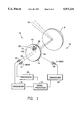
- FIG. 2 is a diagrammatic sectional view of the antenna of FIG. 1;
- FIG. 3 is a plan view of a front surface of the frequency selective element of FIGS. 1 and 2, and wherein the supporting substrate has been deleted to simplify the figure to show the arrangement of radiating elements formed of electrically conductive material;
- FIG. 4 is a sectional view of the frequency selective surface of FIGS. 1 and 2, the view including a substrate for supporting radiating elements on the front surface of the substrate, with the radiating elements being indicated diagrammatically;
- FIG. 5 is a sectional view taken along the line 5--5 in FIG. 3 showing one set of radiating elements in section with the substrate being indicated diagrammatically.
- FIG. 1 shows an antenna system 10 suitable for operation on a satellite circling the earth.
- the system 10 includes an antenna 12 having a frequency selective element 14.
- the front surface 16 of the element 14 becomes a frequency selective surface (FSS) upon placement of radiators, or resonators, upon the surface 16 as will be described hereinafter.
- the FSS may be curved or planar; however, in the preferred embodiment of the invention, the element 14 including the FSS is constructed with a planar form.
- the antenna 12 further comprises a reflector 18 disposed behind the plane of the element 14, an S-band feed in the form of a horn 20 disposed also behind the plane of the element 14, a second horn 22 operative at a lower C-band spectral region and located in front of the plane of the element 14, and a third horn 24 operative in an upper C-band portion of the electromagnetic spectrum and being positioned also in front of the element 14.
- the two C-band horns 22 and 24 are shown by way of example and that, if desired, the invention can be practiced by use of a single wide band horn or other form of feed encompassing the pass bands of both of the horns 22 and 24.
- FIG. 1 indicates a generalized situation wherein any one of the spectral bands may be employed for either up-link or down-link transmission and, accordingly, the three horns 20, 22, and 24 are shown connected, respectively, to transceivers 26, 28, and 30.
- the transceivers 26, 28, and 30 are connected to a signal processor 32 which may provide the functions of modulation and demodulation of signals so as to transfer a signal from an up-link transmission band to a down-link transmission band for transmission back to a location on the earth.
- FIG. 2 shows the positioning of the horn 20 behind a plane 34 of the front surface 16 of the frequency selective element 14, with the horns 22 and 24 located on the opposite side of the plane 34.
- Rays of radiation from the C-band horns 22 and 24 propagate directly through the element 14 to the reflector 18.
- Rays of radiation to the S-band horn 20 propagate along a path from the reflector 18 wherein the propagation path is folded by the FSS of the element 14 as the rays from the reflector 18 are reflected by the FSS to the horn 20.
- the locations of the S-band horn 20 and the cluster of the two C-band horns 22 and 24 are at mirror images of each other about the plane 34.
- the front surface 16 of the element 14 is provided with an array 36 of sets 38 of radiating elements, or radiators, 40 wherein, in each of the sets 38, individual ones of the radiators are nested, one within the other.
- Each of the radiators is formed as a closed, generally circular path of electrically conductive material, a metal such as copper or aluminum being employed in the preferred embodiment of the invention.
- the radiators 40 are deposited on, and are supported by, a substrate 42 of the frequency-selective element 14.
- the substrate 42 is fabricated of dielectric materials, all of which are transparent to the electromagnetic radiation in the frequency bands of the horns 20, 22, and 24.
- the radiators 40 may be circular, or slightly elliptical, or of polygonal shape.
- each of the sets 38 there is a total of three radiators wherein an outermost one of the radiators 40A (shown in FIGS. 3 and 5) is provided with a hexagonal configuration, an innermost one of the radiators 40C (shown in FIGS. 3 and 5) is provided with a circular annular form, and the middle radiator 40B (shown in FIGS. 3 and 5) is provided also with a circular annular form.
- all of the radiators 40 are concentric with each other.
- the outermost radiator 40A may be circular, hexagonal, octagonal, or other polygonal form; however, the hexagonal form is employed in the preferred embodiment of the invention to permit a minimization of the spacing, D, (shown in FIG. 3) between centers 44 (shown in FIGS. 3 and 5) of the nested sets of radiators 40.
- the spacing, D, between the centers 44, and the closest point of approach, d, between adjacent sets 38 are indicated in FIG. 3.
- the inner and the outer radii r 1 and r 2 of the innermost radiator 40C are shown in FIGS. 3 and 5.
- the inner and outer radii r 3 and r 4 of the middle radiator 40B are indicated also in FIGS. 3 and 5.
- the difference in radii, r 2 -r 1 , and the difference in radii r 4 -r 3 provide the width of the innermost and the middle radiators 40C and 40B.
- the width of the outermost radiator 40A is given by W, as shown in FIGS. 3 and 5.
- Adjacent ones of the sets 38 have their centers 44 arranged at the vertices of an equilateral triangle, as shown in FIG. 3, wherein each side of the triangle is identified by the distance D.
- the length L of one side of the hexagon of the outermost radiator 40A in any one of the sets 38 is shown also in FIG. 3.
- the substrate 42 has a lightweight rigid construction which is advantageous in satellite antenna systems.
- the substrate 42 comprises a central honeycomb core 46 enclosed on front and back sides by layers 48 and 50 of plastic film material, such as a polycarbonate, a layer of Kevlar being used in the construction of the front and back layers 48 and 50 in the preferred embodiment of the invention.
- a relatively thin layer 52 of plastic material such as nylon or Upilex is secured adhesively to the front layer 48 to serve as a bed for deposition of the nest 38 of the radiators 40, the Upilex being employed in the preferred embodiment of the invention.
- the honeycomb core 46 has a dielectric constant, similar to that of air, and may be formed of a material such as craft paper, such a material, Nomax being employed in a preferred embodiment of the invention.
- the following dimensions are used in constructing an embodiment of the invention to operate at a specific set of spectral frequency bands, it being understood that, in accordance with the invention, the dimensions of the elements can be scaled to provide for an antenna which functions at higher or lower frequency bands.
- the S-band horn 20 operates at 2.65-2.69 GHz (gigahertz), and serves for receiving signals incident upon the antenna 12.
- the C-band horns 22 and 24 operate, respectively, in bands of 3.7-4.2 GHz and 5.925-6.425 GHz for transmission of electromagnetic signals from the antenna 12. All three of the horns 20, 22, and 24 are operative with circularly polarized waves.
- the radiators 40 are fabricated of copper film deposited in a layer in a range of typically 5-10 mil thickness.
- the thickness may be as low as one mil.
- the minimum thickness should be equal to at least a few times the electromagnetic skin depth of the copper film.
- the width, W, of the radiator 40A has a value in the range of 0.01-0.02 inch, a value of 0.015 inch being employed in the preferred embodiment of the invention.
- This provides for a circumference of the radiator 40A approximately equal to the wavelength of the S-band radiation within the dielectric material of the substrate, thereby enabling the radiator 40A to resonate at the frequency of the S-band radiation.
- construction of the inner annular C-band radiators 40B and 40C with mean values of circumference equal approximately to mean values of their respective bands of radiation allow these radiators to resonate at their respective frequencies.
- the distance D between the centers 44 is equal to 1.73L which is equal approximately to one-third wavelength of the S-band radiation in the dielectric substrate, these being equal approximately to 0.770 inches in the preferred embodiment of the invention.
- the closest point of approach, d is equal to 15 mils.
- the radii r 1 , r 2 , r 3 , and r 4 are equal respectively to 0.70 inches, 0.265 inches, 0.275 inches, and 0.335 inches.
- the following dimensions are used in the construction of the substrate 42.
- the Kevlar layers 48 and 50 each have a thickness in the range of 10-20 mils.
- the honeycomb core 46 has a thickness of one inch.
- the Upilex layer 52 has a thickness in the range of 1-2 mils.
- the dielectric constant of the layers 48, 50, and 52 is in the range of approximately 2.2-2.8.
- an incoming ray 54 (FIGS. 1 and 2) is reflected by the reflector 18 to the element 14 wherein the FSS comprised of the radiator sets 38 acts to reflect the ray 54 to the horn 20.
- the ray 54 is represented by a dashed line wherein the dashes are relatively short.
- An outgoing ray 56 from the horn 22 propagates through the FSS and the element 14 to be reflected by the reflector 18 away from the antenna 12.
- the ray 56 is represented by a dashed line wherein the dashes are relatively long.
- an outgoing ray from the horn 24 propagates through the FSS and the element 14 to be reflected by the reflector 18 away from the antenna 12.
- the horn 20 is capable of receiving radiation from rays anywhere within an input beam which converges to the horn 20 in which the beam width is identified by extreme rays 54A and 54B.
- the maximum angle of incidence of the extreme rays, either 54A or 54B can be as high as 60° relative to a normal to the plane 34.
- the angle of 60° is substantially greater than that which has been available heretofore in the prior art, and represents a significant improvement in the utilization of an antenna, such as the antenna 12, for viewing a part of the earth's surface.
- the beam width of radiation to be emitted by either of the radiators 22 and 24, and to be transmitted through the FSS is comparable in size to the aforementioned beam width of the horn 20. This is indicated in FIG. 2 by extreme rays 56A and 56B, these rays being drawn as dashed lines with relatively large dashes to distinguish these rays from the S-band rays 54, 54A and 54B.
- the spacing between the radiators 40 in each of the sets 38 is substantially smaller than a quarter wavelength of the radiation in the highest frequency band,
- the radiators which, in terms of a mathematical analogy with the components of resistance, capacitance, and inductance of an electronic filter, provide for an overall reflectance/transmission characteristic of the frequency selective element 14 resembling that of a three-pole electronics filter.
- movement of the poles and the zeros in the frequency-transform plane produces a filter response in which a steep transition may occur between a passband and a stop band of the filter.
- the highest reflection frequency is approximately 2.7 GHz while the lowest transmission frequency is 3.7 GHz, this giving a ratio of the two frequencies of 1.37 which is substantially lower that which has been obtainable in the prior art.
- a measure of the improved bandwidth of the frequency selective element 14 is obtained by dividing the maximum transmission frequency of approximately 6.4 GHz by the maximum reflection frequency of approximately 2.7 GHz to give a ratio of 2.37 which is significantly higher than that obtainable in the prior art. Also, the spacing and relative sizes of the radiating elements 40A, 40B, and 40C in respective ones of the sets 38 provides for greater control over grating lobes to attain the aforementioned benefit of the capacity to handle increased angles of incidence of the S-band and the C-band rays 54 and 56 (FIG. 2) relative to the frequency selective element 14.
Landscapes
- Aerials With Secondary Devices (AREA)
- Variable-Direction Aerials And Aerial Arrays (AREA)
Abstract
Description
Claims (17)
Priority Applications (3)
| Application Number | Priority Date | Filing Date | Title |
|---|---|---|---|
| US08/151,501 US5471224A (en) | 1993-11-12 | 1993-11-12 | Frequency selective surface with repeating pattern of concentric closed conductor paths, and antenna having the surface |
| DE4432174A DE4432174A1 (en) | 1993-11-12 | 1994-09-09 | Frequency-selective surface with a repeating pattern of concentric, closed conductive paths, and antenna having such a surface |
| JP6242520A JPH07240625A (en) | 1993-11-12 | 1994-10-06 | Frequency separation device and antenna having it |
Applications Claiming Priority (1)
| Application Number | Priority Date | Filing Date | Title |
|---|---|---|---|
| US08/151,501 US5471224A (en) | 1993-11-12 | 1993-11-12 | Frequency selective surface with repeating pattern of concentric closed conductor paths, and antenna having the surface |
Publications (1)
| Publication Number | Publication Date |
|---|---|
| US5471224A true US5471224A (en) | 1995-11-28 |
Family
ID=22539052
Family Applications (1)
| Application Number | Title | Priority Date | Filing Date |
|---|---|---|---|
| US08/151,501 Expired - Lifetime US5471224A (en) | 1993-11-12 | 1993-11-12 | Frequency selective surface with repeating pattern of concentric closed conductor paths, and antenna having the surface |
Country Status (3)
| Country | Link |
|---|---|
| US (1) | US5471224A (en) |
| JP (1) | JPH07240625A (en) |
| DE (1) | DE4432174A1 (en) |
Cited By (40)
| Publication number | Priority date | Publication date | Assignee | Title |
|---|---|---|---|---|
| EP0803932A1 (en) * | 1994-06-22 | 1997-10-29 | Space Systems / Loral Inc. | Multiple band folding antenna |
| GB2325784A (en) * | 1997-04-29 | 1998-12-02 | Trw Inc | Frequency selective surface filter for an antenna |
| US6072432A (en) * | 1997-05-02 | 2000-06-06 | Radio Frequency Systems, Inc. | Hybrid power tapered/space tapered multi-beam antenna |
| US20020140615A1 (en) * | 1999-09-20 | 2002-10-03 | Carles Puente Baliarda | Multilevel antennae |
| US6512485B2 (en) * | 2001-03-12 | 2003-01-28 | Wildblue Communications, Inc. | Multi-band antenna for bundled broadband satellite internet access and DBS television service |
| US20030112190A1 (en) * | 2000-04-19 | 2003-06-19 | Baliarda Carles Puente | Advanced multilevel antenna for motor vehicles |
| US6678521B1 (en) * | 1998-06-04 | 2004-01-13 | Centre National D'etudes Spatiales | Method for determining amplitudes and phases of the different channels in an electromagnetic signal transmission network, such as a telecommunication satellite antenna |
| US20040008149A1 (en) * | 2002-07-11 | 2004-01-15 | Harris Corporation | Antenna system with active spatial filtering surface |
| WO2004008576A1 (en) * | 2002-07-11 | 2004-01-22 | Harris Corporation | Spatial filtering surface operative with antenna aperture for modifying aperture electric field |
| US6870507B2 (en) | 2001-02-07 | 2005-03-22 | Fractus S.A. | Miniature broadband ring-like microstrip patch antenna |
| US6937206B2 (en) | 2001-04-16 | 2005-08-30 | Fractus, S.A. | Dual-band dual-polarized antenna array |
| US6937191B2 (en) | 1999-10-26 | 2005-08-30 | Fractus, S.A. | Interlaced multiband antenna arrays |
| US6958738B1 (en) * | 2004-04-21 | 2005-10-25 | Harris Corporation | Reflector antenna system including a phased array antenna having a feed-through zone and related methods |
| US20050237264A1 (en) * | 2004-04-21 | 2005-10-27 | Harris Corporation, Corporation Of The State Of Delaware | Reflector antenna system including a phased array antenna operable in multiple modes and related methods |
| US7148850B2 (en) | 2000-01-19 | 2006-12-12 | Fractus, S.A. | Space-filling miniature antennas |
| US7202818B2 (en) | 2001-10-16 | 2007-04-10 | Fractus, S.A. | Multifrequency microstrip patch antenna with parasitic coupled elements |
| US7215287B2 (en) | 2001-10-16 | 2007-05-08 | Fractus S.A. | Multiband antenna |
| US7312762B2 (en) | 2001-10-16 | 2007-12-25 | Fractus, S.A. | Loaded antenna |
| US7511675B2 (en) | 2000-10-26 | 2009-03-31 | Advanced Automotive Antennas, S.L. | Antenna system for a motor vehicle |
| US20090243948A1 (en) * | 2005-11-29 | 2009-10-01 | Ewald Schmidt | Modular unit for a radar antenna array having an integrated hf chip |
| US20100156556A1 (en) * | 2008-08-25 | 2010-06-24 | Fractal Antenna Systems, Inc. | Wideband electromagnetic cloaking systems |
| US20100214183A1 (en) * | 2009-02-25 | 2010-08-26 | The Boeing Company | Transmitting power and data |
| US20110050360A1 (en) * | 2008-08-25 | 2011-03-03 | Fractal Antenna Systems, Inc. | Wideband electromagnetic cloaking systems |
| US20110063189A1 (en) * | 2009-04-15 | 2011-03-17 | Fractal Antenna Systems, Inc. | Methods and Apparatus for Enhanced Radiation Characteristics From Antennas and Related Components |
| US7982687B1 (en) * | 2008-10-02 | 2011-07-19 | The Directv Group, Inc. | Ka/Ku outdoor unit configuration using a frequency selective surface |
| US20120154232A1 (en) * | 2010-12-14 | 2012-06-21 | Isom Robert S | Resistive frequency selective surface circuit for reducing coupling and electromagnetic interference in radar antenna arrays |
| US20130274829A1 (en) * | 2012-04-17 | 2013-10-17 | Boston Scientific Neuromodulation Corporation | Neurostimulation device having frequency selective surface to prevent electromagnetic interference during mri |
| US8738103B2 (en) | 2006-07-18 | 2014-05-27 | Fractus, S.A. | Multiple-body-configuration multimedia and smartphone multifunction wireless devices |
| US20170237148A1 (en) * | 2016-02-16 | 2017-08-17 | GM Global Technology Operations LLC | Impedance surface treatment for mitigating surface waves and improving gain of antennas on glass |
| US9755314B2 (en) | 2001-10-16 | 2017-09-05 | Fractus S.A. | Loaded antenna |
| CN107394410A (en) * | 2017-07-18 | 2017-11-24 | 南京航空航天大学 | The dimension of one kind 2.5 closes ring-like frequency-selective surfaces structure and its design method |
| US10027033B2 (en) | 2008-08-25 | 2018-07-17 | Fractal Antenna Systems, Inc. | Wideband electromagnetic cloaking systems |
| US10199734B2 (en) * | 2013-07-03 | 2019-02-05 | Intellian Technologies Inc. | Antenna for satellite communication having structure for switching multiple band signals |
| US10283872B2 (en) | 2009-04-15 | 2019-05-07 | Fractal Antenna Systems, Inc. | Methods and apparatus for enhanced radiation characteristics from antennas and related components |
| WO2020122837A1 (en) * | 2018-12-14 | 2020-06-18 | Profen İleti̇şi̇m Teknoloji̇leri̇ Ve Hi̇zmetleri̇ Sanayi̇ Ti̇caret Anoni̇m Şi̇rketi̇ | Secondary reflector with frequency selective surface |
| CN111370863A (en) * | 2020-03-19 | 2020-07-03 | 北京环境特性研究所 | Structure for Ku and Ka dual-band wave transmission |
| CN112350066A (en) * | 2020-10-28 | 2021-02-09 | 北京环境特性研究所 | Filtering structure and radome |
| US11196173B1 (en) * | 2021-06-25 | 2021-12-07 | King Abdulaziz University | Dual-band (S and C) sub-reflectors for frequency-reuse types of satellite communication systems for commercial and defense applications |
| US11268837B1 (en) | 2018-05-30 | 2022-03-08 | Fractal Antenna Systems, Inc. | Conformal aperture engine sensors and mesh network |
| US11532890B2 (en) * | 2018-12-31 | 2022-12-20 | Hughes Network Systems, Llc | Frequency selective surface zoning technique to reduce the complication in design from large range of illumination incident angles |
Families Citing this family (2)
| Publication number | Priority date | Publication date | Assignee | Title |
|---|---|---|---|---|
| DE102006061312A1 (en) * | 2006-12-22 | 2008-06-26 | Giesecke & Devrient Gmbh | Antenna for measuring movement information according to the Doppler principle, transponder, system and method |
| US8749446B2 (en) * | 2011-07-29 | 2014-06-10 | The Boeing Company | Wide-band linked-ring antenna element for phased arrays |
Citations (6)
| Publication number | Priority date | Publication date | Assignee | Title |
|---|---|---|---|---|
| US3189907A (en) * | 1961-08-11 | 1965-06-15 | Lylnan F Van Buskirk | Zone plate radio transmission system |
| US3394378A (en) * | 1964-11-16 | 1968-07-23 | Radiation Inc | Multiple reflector multiple frequency band antenna system |
| JPS59169206A (en) * | 1983-03-16 | 1984-09-25 | Mitsubishi Electric Corp | Antenna device |
| US4495506A (en) * | 1982-04-05 | 1985-01-22 | Motorola, Inc. | Image spatial filter |
| US5130718A (en) * | 1990-10-23 | 1992-07-14 | Hughes Aircraft Company | Multiple dichroic surface cassegrain reflector |
| US5162809A (en) * | 1990-10-23 | 1992-11-10 | Hughes Aircraft Company | Polarization independent frequency selective surface for diplexing two closely spaced frequency bands |
-
1993
- 1993-11-12 US US08/151,501 patent/US5471224A/en not_active Expired - Lifetime
-
1994
- 1994-09-09 DE DE4432174A patent/DE4432174A1/en not_active Withdrawn
- 1994-10-06 JP JP6242520A patent/JPH07240625A/en active Pending
Patent Citations (6)
| Publication number | Priority date | Publication date | Assignee | Title |
|---|---|---|---|---|
| US3189907A (en) * | 1961-08-11 | 1965-06-15 | Lylnan F Van Buskirk | Zone plate radio transmission system |
| US3394378A (en) * | 1964-11-16 | 1968-07-23 | Radiation Inc | Multiple reflector multiple frequency band antenna system |
| US4495506A (en) * | 1982-04-05 | 1985-01-22 | Motorola, Inc. | Image spatial filter |
| JPS59169206A (en) * | 1983-03-16 | 1984-09-25 | Mitsubishi Electric Corp | Antenna device |
| US5130718A (en) * | 1990-10-23 | 1992-07-14 | Hughes Aircraft Company | Multiple dichroic surface cassegrain reflector |
| US5162809A (en) * | 1990-10-23 | 1992-11-10 | Hughes Aircraft Company | Polarization independent frequency selective surface for diplexing two closely spaced frequency bands |
Non-Patent Citations (2)
| Title |
|---|
| J. Huang, et al., "Tri-Band Frequency Selective Surface with Circular Ring Elements", IEEE, 1991, pp. 204-207. |
| J. Huang, et al., Tri Band Frequency Selective Surface with Circular Ring Elements , IEEE, 1991, pp. 204 207. * |
Cited By (120)
| Publication number | Priority date | Publication date | Assignee | Title |
|---|---|---|---|---|
| EP0803932A1 (en) * | 1994-06-22 | 1997-10-29 | Space Systems / Loral Inc. | Multiple band folding antenna |
| GB2325784A (en) * | 1997-04-29 | 1998-12-02 | Trw Inc | Frequency selective surface filter for an antenna |
| US5949387A (en) * | 1997-04-29 | 1999-09-07 | Trw Inc. | Frequency selective surface (FSS) filter for an antenna |
| GB2325784B (en) * | 1997-04-29 | 2000-02-09 | Trw Inc | Frequency selective surface filter for an antenna |
| US6072432A (en) * | 1997-05-02 | 2000-06-06 | Radio Frequency Systems, Inc. | Hybrid power tapered/space tapered multi-beam antenna |
| US6678521B1 (en) * | 1998-06-04 | 2004-01-13 | Centre National D'etudes Spatiales | Method for determining amplitudes and phases of the different channels in an electromagnetic signal transmission network, such as a telecommunication satellite antenna |
| US8154462B2 (en) | 1999-09-20 | 2012-04-10 | Fractus, S.A. | Multilevel antennae |
| US8330659B2 (en) | 1999-09-20 | 2012-12-11 | Fractus, S.A. | Multilevel antennae |
| US10056682B2 (en) | 1999-09-20 | 2018-08-21 | Fractus, S.A. | Multilevel antennae |
| US9761934B2 (en) | 1999-09-20 | 2017-09-12 | Fractus, S.A. | Multilevel antennae |
| US9362617B2 (en) | 1999-09-20 | 2016-06-07 | Fractus, S.A. | Multilevel antennae |
| US9240632B2 (en) | 1999-09-20 | 2016-01-19 | Fractus, S.A. | Multilevel antennae |
| US9054421B2 (en) | 1999-09-20 | 2015-06-09 | Fractus, S.A. | Multilevel antennae |
| US9000985B2 (en) | 1999-09-20 | 2015-04-07 | Fractus, S.A. | Multilevel antennae |
| US8976069B2 (en) | 1999-09-20 | 2015-03-10 | Fractus, S.A. | Multilevel antennae |
| US8941541B2 (en) | 1999-09-20 | 2015-01-27 | Fractus, S.A. | Multilevel antennae |
| US7397431B2 (en) | 1999-09-20 | 2008-07-08 | Fractus, S.A. | Multilevel antennae |
| US7394432B2 (en) | 1999-09-20 | 2008-07-01 | Fractus, S.A. | Multilevel antenna |
| US20020140615A1 (en) * | 1999-09-20 | 2002-10-03 | Carles Puente Baliarda | Multilevel antennae |
| US7528782B2 (en) | 1999-09-20 | 2009-05-05 | Fractus, S.A. | Multilevel antennae |
| US8009111B2 (en) | 1999-09-20 | 2011-08-30 | Fractus, S.A. | Multilevel antennae |
| US7015868B2 (en) | 1999-09-20 | 2006-03-21 | Fractus, S.A. | Multilevel Antennae |
| US7123208B2 (en) | 1999-09-20 | 2006-10-17 | Fractus, S.A. | Multilevel antennae |
| US8154463B2 (en) | 1999-09-20 | 2012-04-10 | Fractus, S.A. | Multilevel antennae |
| US7505007B2 (en) | 1999-09-20 | 2009-03-17 | Fractus, S.A. | Multi-level antennae |
| US8228256B2 (en) | 1999-10-26 | 2012-07-24 | Fractus, S.A. | Interlaced multiband antenna arrays |
| US7932870B2 (en) | 1999-10-26 | 2011-04-26 | Fractus, S.A. | Interlaced multiband antenna arrays |
| US7557768B2 (en) | 1999-10-26 | 2009-07-07 | Fractus, S.A. | Interlaced multiband antenna arrays |
| US7250918B2 (en) | 1999-10-26 | 2007-07-31 | Fractus, S.A. | Interlaced multiband antenna arrays |
| US9905940B2 (en) | 1999-10-26 | 2018-02-27 | Fractus, S.A. | Interlaced multiband antenna arrays |
| US8896493B2 (en) | 1999-10-26 | 2014-11-25 | Fractus, S.A. | Interlaced multiband antenna arrays |
| US6937191B2 (en) | 1999-10-26 | 2005-08-30 | Fractus, S.A. | Interlaced multiband antenna arrays |
| US8471772B2 (en) | 2000-01-19 | 2013-06-25 | Fractus, S.A. | Space-filling miniature antennas |
| US20110177839A1 (en) * | 2000-01-19 | 2011-07-21 | Fractus, S.A. | Space-filling miniature antennas |
| US8610627B2 (en) | 2000-01-19 | 2013-12-17 | Fractus, S.A. | Space-filling miniature antennas |
| US8558741B2 (en) | 2000-01-19 | 2013-10-15 | Fractus, S.A. | Space-filling miniature antennas |
| US9331382B2 (en) | 2000-01-19 | 2016-05-03 | Fractus, S.A. | Space-filling miniature antennas |
| US7554490B2 (en) | 2000-01-19 | 2009-06-30 | Fractus, S.A. | Space-filling miniature antennas |
| US8212726B2 (en) | 2000-01-19 | 2012-07-03 | Fractus, Sa | Space-filling miniature antennas |
| US8207893B2 (en) | 2000-01-19 | 2012-06-26 | Fractus, S.A. | Space-filling miniature antennas |
| US10355346B2 (en) | 2000-01-19 | 2019-07-16 | Fractus, S.A. | Space-filling miniature antennas |
| US7148850B2 (en) | 2000-01-19 | 2006-12-12 | Fractus, S.A. | Space-filling miniature antennas |
| US7164386B2 (en) | 2000-01-19 | 2007-01-16 | Fractus, S.A. | Space-filling miniature antennas |
| US7202822B2 (en) | 2000-01-19 | 2007-04-10 | Fractus, S.A. | Space-filling miniature antennas |
| US20110181478A1 (en) * | 2000-01-19 | 2011-07-28 | Fractus, S.A. | Space-filling miniature antennas |
| US20110181481A1 (en) * | 2000-01-19 | 2011-07-28 | Fractus, S.A. | Space-filling miniature antennas |
| US20030112190A1 (en) * | 2000-04-19 | 2003-06-19 | Baliarda Carles Puente | Advanced multilevel antenna for motor vehicles |
| US6809692B2 (en) | 2000-04-19 | 2004-10-26 | Advanced Automotive Antennas, S.L. | Advanced multilevel antenna for motor vehicles |
| US7511675B2 (en) | 2000-10-26 | 2009-03-31 | Advanced Automotive Antennas, S.L. | Antenna system for a motor vehicle |
| US6870507B2 (en) | 2001-02-07 | 2005-03-22 | Fractus S.A. | Miniature broadband ring-like microstrip patch antenna |
| US6512485B2 (en) * | 2001-03-12 | 2003-01-28 | Wildblue Communications, Inc. | Multi-band antenna for bundled broadband satellite internet access and DBS television service |
| US6937206B2 (en) | 2001-04-16 | 2005-08-30 | Fractus, S.A. | Dual-band dual-polarized antenna array |
| US7312762B2 (en) | 2001-10-16 | 2007-12-25 | Fractus, S.A. | Loaded antenna |
| US7920097B2 (en) | 2001-10-16 | 2011-04-05 | Fractus, S.A. | Multiband antenna |
| US7215287B2 (en) | 2001-10-16 | 2007-05-08 | Fractus S.A. | Multiband antenna |
| US8228245B2 (en) | 2001-10-16 | 2012-07-24 | Fractus, S.A. | Multiband antenna |
| US7541997B2 (en) | 2001-10-16 | 2009-06-02 | Fractus, S.A. | Loaded antenna |
| US7202818B2 (en) | 2001-10-16 | 2007-04-10 | Fractus, S.A. | Multifrequency microstrip patch antenna with parasitic coupled elements |
| US8723742B2 (en) | 2001-10-16 | 2014-05-13 | Fractus, S.A. | Multiband antenna |
| US9755314B2 (en) | 2001-10-16 | 2017-09-05 | Fractus S.A. | Loaded antenna |
| US7439923B2 (en) | 2001-10-16 | 2008-10-21 | Fractus, S.A. | Multiband antenna |
| US6885355B2 (en) * | 2002-07-11 | 2005-04-26 | Harris Corporation | Spatial filtering surface operative with antenna aperture for modifying aperture electric field |
| WO2004008576A1 (en) * | 2002-07-11 | 2004-01-22 | Harris Corporation | Spatial filtering surface operative with antenna aperture for modifying aperture electric field |
| US6806843B2 (en) | 2002-07-11 | 2004-10-19 | Harris Corporation | Antenna system with active spatial filtering surface |
| US20040008149A1 (en) * | 2002-07-11 | 2004-01-15 | Harris Corporation | Antenna system with active spatial filtering surface |
| US6965355B1 (en) * | 2004-04-21 | 2005-11-15 | Harris Corporation | Reflector antenna system including a phased array antenna operable in multiple modes and related methods |
| US20050237264A1 (en) * | 2004-04-21 | 2005-10-27 | Harris Corporation, Corporation Of The State Of Delaware | Reflector antenna system including a phased array antenna operable in multiple modes and related methods |
| US20050237266A1 (en) * | 2004-04-21 | 2005-10-27 | Harris Corporation, Corporation Of The State Of Delaware | Reflector antenna system including a phased array antenna having a feed-through zone and related methods |
| US6958738B1 (en) * | 2004-04-21 | 2005-10-25 | Harris Corporation | Reflector antenna system including a phased array antenna having a feed-through zone and related methods |
| US20090243948A1 (en) * | 2005-11-29 | 2009-10-01 | Ewald Schmidt | Modular unit for a radar antenna array having an integrated hf chip |
| US9099773B2 (en) | 2006-07-18 | 2015-08-04 | Fractus, S.A. | Multiple-body-configuration multimedia and smartphone multifunction wireless devices |
| US11735810B2 (en) | 2006-07-18 | 2023-08-22 | Fractus, S.A. | Multiple-body-configuration multimedia and smartphone multifunction wireless devices |
| US8738103B2 (en) | 2006-07-18 | 2014-05-27 | Fractus, S.A. | Multiple-body-configuration multimedia and smartphone multifunction wireless devices |
| US10644380B2 (en) | 2006-07-18 | 2020-05-05 | Fractus, S.A. | Multiple-body-configuration multimedia and smartphone multifunction wireless devices |
| US11031677B2 (en) | 2006-07-18 | 2021-06-08 | Fractus, S.A. | Multiple-body-configuration multimedia and smartphone multifunction wireless devices |
| US11349200B2 (en) | 2006-07-18 | 2022-05-31 | Fractus, S.A. | Multiple-body-configuration multimedia and smartphone multifunction wireless devices |
| US9899727B2 (en) | 2006-07-18 | 2018-02-20 | Fractus, S.A. | Multiple-body-configuration multimedia and smartphone multifunction wireless devices |
| US12095149B2 (en) | 2006-07-18 | 2024-09-17 | Fractus, S.A. | Multiple-body-configuration multimedia and smartphone multifunction wireless devices |
| US10727603B2 (en) | 2008-08-25 | 2020-07-28 | Fractal Antenna Systems, Inc. | Wideband electromagnetic cloaking systems |
| US9166302B2 (en) * | 2008-08-25 | 2015-10-20 | Fractal Antenna Systems, Inc. | Wideband electromagnetic cloaking systems |
| US8253639B2 (en) * | 2008-08-25 | 2012-08-28 | Nathan Cohen | Wideband electromagnetic cloaking systems |
| US10027033B2 (en) | 2008-08-25 | 2018-07-17 | Fractal Antenna Systems, Inc. | Wideband electromagnetic cloaking systems |
| US20110050360A1 (en) * | 2008-08-25 | 2011-03-03 | Fractal Antenna Systems, Inc. | Wideband electromagnetic cloaking systems |
| US8937579B2 (en) | 2008-08-25 | 2015-01-20 | Fractal Antenna Systems, Inc. | Wideband electromagnetic cloaking systems |
| US10038230B2 (en) | 2008-08-25 | 2018-07-31 | Fractal Antenna Systems, Inc. | Wideband electromagnetic cloaking systems |
| US20100156556A1 (en) * | 2008-08-25 | 2010-06-24 | Fractal Antenna Systems, Inc. | Wideband electromagnetic cloaking systems |
| US7982687B1 (en) * | 2008-10-02 | 2011-07-19 | The Directv Group, Inc. | Ka/Ku outdoor unit configuration using a frequency selective surface |
| US8421692B2 (en) * | 2009-02-25 | 2013-04-16 | The Boeing Company | Transmitting power and data |
| US20100214183A1 (en) * | 2009-02-25 | 2010-08-26 | The Boeing Company | Transmitting power and data |
| US8730113B2 (en) | 2009-02-25 | 2014-05-20 | The Boeing Company | Transmitting power and data |
| US9035849B2 (en) * | 2009-04-15 | 2015-05-19 | Fractal Antenna Systems, Inc. | Methods and apparatus for enhanced radiation characteristics from antennas and related components |
| US20110063189A1 (en) * | 2009-04-15 | 2011-03-17 | Fractal Antenna Systems, Inc. | Methods and Apparatus for Enhanced Radiation Characteristics From Antennas and Related Components |
| US20150255861A1 (en) * | 2009-04-15 | 2015-09-10 | Fractal Antenna Systems, Inc. | Methods and apparatus for enhanced radiation characteristics from antennas and related components |
| US10014586B2 (en) | 2009-04-15 | 2018-07-03 | Fractal Antenna Systems, Inc. | Method and apparatus for enhanced radiation characteristics from antennas and related components |
| US10854987B2 (en) | 2009-04-15 | 2020-12-01 | Fractal Antenna Systems, Inc. | Methods and apparatus for enhanced radiation characteristics from antennas and related components |
| US10283872B2 (en) | 2009-04-15 | 2019-05-07 | Fractal Antenna Systems, Inc. | Methods and apparatus for enhanced radiation characteristics from antennas and related components |
| US9620853B2 (en) * | 2009-04-15 | 2017-04-11 | Fractal Antenna Systems, Inc. | Methods and apparatus for enhanced radiation characteristics from antennas and related components |
| US10483649B2 (en) | 2009-04-15 | 2019-11-19 | Fractal Antenna Systems, Inc. | Methods and apparatus for enhanced radiation characteristics from antennas and related components |
| US20120154232A1 (en) * | 2010-12-14 | 2012-06-21 | Isom Robert S | Resistive frequency selective surface circuit for reducing coupling and electromagnetic interference in radar antenna arrays |
| US8681064B2 (en) * | 2010-12-14 | 2014-03-25 | Raytheon Company | Resistive frequency selective surface circuit for reducing coupling and electromagnetic interference in radar antenna arrays |
| US20130274829A1 (en) * | 2012-04-17 | 2013-10-17 | Boston Scientific Neuromodulation Corporation | Neurostimulation device having frequency selective surface to prevent electromagnetic interference during mri |
| US10615504B2 (en) * | 2013-07-03 | 2020-04-07 | Intellian Technologies Inc | Antenna for satellite communication having structure for switching multiple band signals |
| US20190157765A1 (en) * | 2013-07-03 | 2019-05-23 | Intellian Technologies Inc. | Antenna for satellite communication having structure for switching multiple band signals |
| US10199734B2 (en) * | 2013-07-03 | 2019-02-05 | Intellian Technologies Inc. | Antenna for satellite communication having structure for switching multiple band signals |
| US20170237148A1 (en) * | 2016-02-16 | 2017-08-17 | GM Global Technology Operations LLC | Impedance surface treatment for mitigating surface waves and improving gain of antennas on glass |
| CN107086350A (en) * | 2016-02-16 | 2017-08-22 | 通用汽车环球科技运作有限责任公司 | For mitigating surface wave and improving the impedance surface treating part of glass antenna gain |
| CN107086350B (en) * | 2016-02-16 | 2020-02-14 | 通用汽车环球科技运作有限责任公司 | Impedance surface treatment for reducing surface waves and improving antenna gain on glass |
| US10446907B2 (en) * | 2016-02-16 | 2019-10-15 | GM Global Technology Operations LLC | Impedance surface treatment for mitigating surface waves and improving gain of antennas on glass |
| CN107394410A (en) * | 2017-07-18 | 2017-11-24 | 南京航空航天大学 | The dimension of one kind 2.5 closes ring-like frequency-selective surfaces structure and its design method |
| CN107394410B (en) * | 2017-07-18 | 2023-08-01 | 南京航空航天大学 | A 2.5-dimensional closed loop frequency selective surface structure and its design method |
| US11662233B2 (en) | 2018-05-30 | 2023-05-30 | Fractal Antenna Systems, Inc. | Conformal aperture engine sensors and mesh network |
| US12146769B2 (en) | 2018-05-30 | 2024-11-19 | Fractal Antenna Systems, Inc. | Conformal aperture engine sensors and mesh network |
| US11268837B1 (en) | 2018-05-30 | 2022-03-08 | Fractal Antenna Systems, Inc. | Conformal aperture engine sensors and mesh network |
| US11342681B2 (en) | 2018-12-14 | 2022-05-24 | Profen Iletisim Teknolojileri Ve Hizmetleri Sanayi Ticaret Anonim Sirketi | Secondary reflector with frequency selective surface |
| WO2020122837A1 (en) * | 2018-12-14 | 2020-06-18 | Profen İleti̇şi̇m Teknoloji̇leri̇ Ve Hi̇zmetleri̇ Sanayi̇ Ti̇caret Anoni̇m Şi̇rketi̇ | Secondary reflector with frequency selective surface |
| US11532890B2 (en) * | 2018-12-31 | 2022-12-20 | Hughes Network Systems, Llc | Frequency selective surface zoning technique to reduce the complication in design from large range of illumination incident angles |
| CN111370863A (en) * | 2020-03-19 | 2020-07-03 | 北京环境特性研究所 | Structure for Ku and Ka dual-band wave transmission |
| CN112350066B (en) * | 2020-10-28 | 2023-05-16 | 北京环境特性研究所 | Filtering structure and radar antenna housing |
| CN112350066A (en) * | 2020-10-28 | 2021-02-09 | 北京环境特性研究所 | Filtering structure and radome |
| US11196173B1 (en) * | 2021-06-25 | 2021-12-07 | King Abdulaziz University | Dual-band (S and C) sub-reflectors for frequency-reuse types of satellite communication systems for commercial and defense applications |
Also Published As
| Publication number | Publication date |
|---|---|
| DE4432174A1 (en) | 1997-03-27 |
| JPH07240625A (en) | 1995-09-12 |
Similar Documents
| Publication | Publication Date | Title |
|---|---|---|
| US5471224A (en) | Frequency selective surface with repeating pattern of concentric closed conductor paths, and antenna having the surface | |
| US5557292A (en) | Multiple band folding antenna | |
| EP1020953B1 (en) | Multi-pattern antenna having frequency selective or polarization sensitive zones | |
| US5949387A (en) | Frequency selective surface (FSS) filter for an antenna | |
| US4115782A (en) | Microwave antenna system | |
| EP2297818B1 (en) | Antenna array with metamaterial lens | |
| US4342036A (en) | Multiple frequency band, multiple beam microwave antenna system | |
| US5175561A (en) | Single-layered radial line slot antenna | |
| US4343005A (en) | Microwave antenna system having enhanced band width and reduced cross-polarization | |
| US5892485A (en) | Dual frequency reflector antenna feed element | |
| US5543809A (en) | Reflectarray antenna for communication satellite frequency re-use applications | |
| US4772890A (en) | Multi-band planar antenna array | |
| US9478861B2 (en) | Dual-band multiple beam reflector antenna for broadband satellites | |
| US3394378A (en) | Multiple reflector multiple frequency band antenna system | |
| US6208309B1 (en) | Dual depth aperture chokes for dual frequency horn equalizing E and H-plane patterns | |
| US5283591A (en) | Fixed-reflector antenna for plural telecommunication beams | |
| US4851858A (en) | Reflector antenna for operation in more than one frequency band | |
| US3681772A (en) | Modulated arm width spiral antenna | |
| US6285332B1 (en) | Frequency selective reflector | |
| US6759994B2 (en) | Multiple beam antenna using reflective and partially reflective surfaces | |
| EP0986133A2 (en) | Multi-focus reflector antenna | |
| US6424312B2 (en) | Radiating source for a transmit and receive antenna intended to be installed on board a satellite | |
| EP1137102A2 (en) | Frequency variable aperture reflector | |
| JP2001127537A (en) | Lens antenna system | |
| US5995056A (en) | Wide band tem fed phased array reflector antenna |
Legal Events
| Date | Code | Title | Description |
|---|---|---|---|
| AS | Assignment |
Owner name: SPACE SYSTEMS/LORAL, INC., CALIFORNIA Free format text: ASSIGNMENT OF ASSIGNORS INTEREST;ASSIGNOR:BARKESHLI, SINA;REEL/FRAME:006859/0539 Effective date: 19931230 |
|
| STCF | Information on status: patent grant |
Free format text: PATENTED CASE |
|
| FEPP | Fee payment procedure |
Free format text: PAYOR NUMBER ASSIGNED (ORIGINAL EVENT CODE: ASPN); ENTITY STATUS OF PATENT OWNER: LARGE ENTITY |
|
| FPAY | Fee payment |
Year of fee payment: 4 |
|
| AS | Assignment |
Owner name: BANK OF AMERICA, N.A. AS COLLATERAL AGENT, NORTH C Free format text: SECURITY INTEREST;ASSIGNOR:SPACE SYSTEMS/LORAL, INC.;REEL/FRAME:013000/0580 Effective date: 20011221 |
|
| FPAY | Fee payment |
Year of fee payment: 8 |
|
| AS | Assignment |
Owner name: SPACE SYSTEMS/LORAL, INC., CALIFORNIA Free format text: RELEASE OF SECURITY INTEREST;ASSIGNOR:BANK OF AMERICA, N.A.;REEL/FRAME:016153/0507 Effective date: 20040802 |
|
| FPAY | Fee payment |
Year of fee payment: 12 |
|
| AS | Assignment |
Owner name: JPMORGAN CHASE BANK, N.A., AS ADMINISTRATIVE AGENT Free format text: SECURITY AGREEMENT;ASSIGNOR:SPACE SYSTEMS/LORAL, INC.;REEL/FRAME:021965/0173 Effective date: 20081016 |
|
| AS | Assignment |
Owner name: SPACE SYSTEMS/LORAL, INC., CALIFORNIA Free format text: TERMINATION AND RELEASE OF SECURITY INTEREST IN PATENT RIGHTS;ASSIGNOR:JPMORGAN CHASE BANK, N.A.;REEL/FRAME:029228/0203 Effective date: 20121102 |
|
| AS | Assignment |
Owner name: SPACE SYSTEMS/LORAL, LLC, CALIFORNIA Free format text: CHANGE OF NAME;ASSIGNOR:SPACE SYSTEMS/LORAL, INC.;REEL/FRAME:030291/0536 Effective date: 20121102 |
|
| AS | Assignment |
Owner name: ROYAL BANK OF CANADA, CANADA Free format text: SECURITY AGREEMENT;ASSIGNOR:SPACE SYSTEMS/LORAL, LLC;REEL/FRAME:030311/0961 Effective date: 20121102 |
|
| AS | Assignment |
Owner name: ROYAL BANK OF CANADA, AS THE COLLATERAL AGENT, CANADA Free format text: SECURITY INTEREST;ASSIGNORS:DIGITALGLOBE, INC.;MACDONALD, DETTWILER AND ASSOCIATES LTD.;MACDONALD, DETTWILER AND ASSOCIATES CORPORATION;AND OTHERS;REEL/FRAME:044167/0396 Effective date: 20171005 Owner name: ROYAL BANK OF CANADA, AS THE COLLATERAL AGENT, CAN Free format text: SECURITY INTEREST;ASSIGNORS:DIGITALGLOBE, INC.;MACDONALD, DETTWILER AND ASSOCIATES LTD.;MACDONALD, DETTWILER AND ASSOCIATES CORPORATION;AND OTHERS;REEL/FRAME:044167/0396 Effective date: 20171005 |
|
| AS | Assignment |
Owner name: MAXAR SPACE LLC, CALIFORNIA Free format text: TERMINATION AND RELEASE OF SECURITY INTEREST IN PATENTS AND TRADEMARKS - RELEASE OF REEL/FRAME 044167/0396;ASSIGNOR:ROYAL BANK OF CANADA, AS AGENT;REEL/FRAME:063543/0001 Effective date: 20230503 Owner name: MAXAR INTELLIGENCE INC., COLORADO Free format text: TERMINATION AND RELEASE OF SECURITY INTEREST IN PATENTS AND TRADEMARKS - RELEASE OF REEL/FRAME 044167/0396;ASSIGNOR:ROYAL BANK OF CANADA, AS AGENT;REEL/FRAME:063543/0001 Effective date: 20230503 |