US5436930A - Simultaneous analog and digital communications with a selection of different signal point constellations based on signal energy - Google Patents
Simultaneous analog and digital communications with a selection of different signal point constellations based on signal energy Download PDFInfo
- Publication number
- US5436930A US5436930A US08/076,516 US7651693A US5436930A US 5436930 A US5436930 A US 5436930A US 7651693 A US7651693 A US 7651693A US 5436930 A US5436930 A US 5436930A
- Authority
- US
- United States
- Prior art keywords
- signal
- monitoring
- amplitude
- communication method
- analog
- Prior art date
- Legal status (The legal status is an assumption and is not a legal conclusion. Google has not performed a legal analysis and makes no representation as to the accuracy of the status listed.)
- Expired - Lifetime
Links
Images


Classifications
-
- H—ELECTRICITY
- H04—ELECTRIC COMMUNICATION TECHNIQUE
- H04L—TRANSMISSION OF DIGITAL INFORMATION, e.g. TELEGRAPHIC COMMUNICATION
- H04L27/00—Modulated-carrier systems
- H04L27/32—Carrier systems characterised by combinations of two or more of the types covered by groups H04L27/02, H04L27/10, H04L27/18 or H04L27/26
- H04L27/34—Amplitude- and phase-modulated carrier systems, e.g. quadrature-amplitude modulated carrier systems
- H04L27/345—Modifications of the signal space to allow the transmission of additional information
- H04L27/3461—Modifications of the signal space to allow the transmission of additional information in order to transmit a subchannel
- H04L27/3483—Modifications of the signal space to allow the transmission of additional information in order to transmit a subchannel using a modulation of the constellation points
-
- H—ELECTRICITY
- H04—ELECTRIC COMMUNICATION TECHNIQUE
- H04J—MULTIPLEX COMMUNICATION
- H04J7/00—Multiplex systems in which the amplitudes or durations of the signals in individual channels are characteristic of those channels
Definitions
- This invention relates to simultaneous transmission of analog and digital signals and, more particularly, to simultaneous transmission of analog signals and digital signals in a non-multiplexed manner and in a co-extensive frequency band.
- voice and data when voice and data is transmitted simultaneously over a channel, it is typically transmitted either via frequency-division multiplexing or time-division multiplexing.
- frequency-division multiplexing the data channel and the voice channel are allocated different sub-bands of the channel's bandwidth. Examples of that are U.S. Pat. No. 4,757,495, U.S. Pat. No. 4,672,602, and U.S. Pat. No. 4,546,212.
- time-division multiplexing arrangements voice signals are sampled, digitized and interleaved with digital data to form a single information stream which is communicated over the available channel. Practically every digital carrier system (e.g. the T1 carrier system) is an example of that.
- U.S. Pat. No. 4,512,013, issued Apr. 16, 1985 presents an interesting approach that is close to a frequency division multiplexing arrangement for simultaneous voice and data.
- the arrangement filters the speech signal and adds thereto a modulated narrowband signal to form the transmitted signal.
- the narrowband modulated signal derives from a narrowband digital input signal that is modulated with a carrier, thereby shifting the narrow-band up in frequency to a position in the spectrum where there is little speech energy.
- the digital signal is recovered through appropriate demodulation. Thereafter, the recovered digital signal is remodulated to replicate the transmitter's operation, adaptively filtered to account for channel characteristics, and subtracted from the received signal.
- a modem filters the digital signal (i.e., shifts it in frequency) to form a band-limited signal and modulates that signal to reside within the passband of the communication channel.
- that passband may be between 300 Hz and 3500 Hz.
- Quadrature modulation is often depicted as a two-dimensional signal space. Use of the signal space to send voice information is disclosed in U.S. Pat. No. 5,081,647 issued Jan. 14, 1992.
- Ajashi et al Use of the signal space to send data and voice in described is "High Speed Digital and Analog Parallel Transmission Technique Over Single Telephone Channel", Ajashi et al, IEEE Transactions on Communications, Vol. 30, No. 5, May, 1982, pp. 1213-1218. Unlike prior techniques, where analog and data were segregated into different time slots (TDM) or different frequency bands (FDM), they describe separating analog and data signals into the two different channels of the QAM system. That is, Ajashi et al suggest modulating the in-phase channel with the analog signal, and modulating the quadrature channel with the data signal.
- TDM time slots
- FDM frequency bands
- the present invention varies the density of a symbol or signal point constellation used to send data based on the energy of an analog signal that is added to the data signal.
- the density of the symbol constellation is increased to take advantage of a lower amplitude analog signal that is added to the data signal.
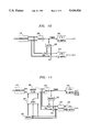
- FIG. 1 presents the basic structure of a prior art modem
- FIG. 2 shows the signal space and an illustrative signal constellation for the FIG. 1 system
- FIG. 3 shows the signal space of a QAM analog system
- FIG. 4 shows the signal space of an alternating digital and analog system
- FIG. 5 shows the signal space of a combined digital and analog system
- FIG. 6 presents one embodiment of a transmitter section for a combined digital and analog system
- FIG. 7 presents one orthogonal modulation approach
- FIG. 8 depicts the vector addition that forms the signal space of FIG. 5;
- FIG. 9 illustrates the arrangements that permit more than one analog signal source to be transmitted simultaneously
- FIG. 10 details the major elements in a receiver in accordance with the principles of this invention.
- FIG. 11 presents a block diagram of a receiver that includes adaptive equalization
- FIG. 12 presents the block diagram of an entire modem
- FIG. 13 presents a slightly different embodiment of the FIG. 12 modem
- FIG. 14 depicts one structure for scrambling analog samples
- FIG. 15 illustrates a four-symbol or signal point constellation where the regions around each signal point may be occupied by an analog signal
- FIG. 16 illustrates a higher density symbol or signal point constellation where the regions around each signal point may be occupied by a lower amplitude analog signal
- FIG. 17 illustrates a block diagram of a transmitter that embodies the present invention.
- FIG. 1 presents a very basic block diagram of a modem that communicates digital data via quadrature modulation techniques.
- Section 100 is the modem's transmitter section and section 200 is the modem's receiver section.
- digital data is applied in FIG. 1 to a 1-to-2 mapper 110, and mapper 110 develops two outputs which typically are referred to as the in-phase and quadrature samples.
- the in-phase samples are applied via low pass filter 150 to modulator 120, which multiplies the applied signal by a carder--i.e, sin ⁇ t in FIG. 1.
- the quadrature samples are applied via low pass filter 160 to modulator 130, which multiplies the applied signal by a second carder.
- the second carrier is orthogonal to the first carrier; namely, cos ⁇ t.
- Filters 150 and 160 must be bandlimited to no more than ⁇ , in order to avoid aliasing and to at least half the inverse of the output sample rate of mapper 110.
- the output signals of modulators 120 and 130 are added in element 140 to develop the analog signal of the modem's transmitter section.
- the digital data applied to the FIG. 1 apparatus is a stream of bits.
- Element 110 views the incoming signal as a stream of symbols that each comprises a preselected number of consecutive bits, and maps each symbol into an in-phase analog sample and a quadrature analog sample.
- the in-phase and quadrature samples delivered by element 110 in effect, specify a location in the signal space of FIG. 2. Accordingly, the set of possible samples that element 110 can produce corresponds to a set of sample points (i.e., a constellation of points) in the signal space depiction of FIG. 2.
- a 4-point signal constellation is shown, by way of illustration, in FIG. 2. It is well known, however, that one can create signal point constellations with a larger number of signal points.
- the signal space can be divided into regions and the receiver's decision is made with respect to the region in which the received signal is located. We call these regions "neighborhood" regions.
- the modulated signal is applied to demodulator 210.
- Demodulator 210 recovers the in-phase and quadrature components and applies them to slicer 220.
- Slicer 220 converts the in-phase and quadrature components into symbols and applies the symbols to de-mapper 230.
- De-mapper 230 maps the symbols into bit streams to form the recovered digital data stream.
- the signal received by demodulator 210 would be precisely the same as the signal sent by adder 140, and a determination of neighborhood regions in which the signal is found (by slicer 220) would be relatively simple and error-free.
- noise that is added to the transmitted signal shifts the received signal in the signal space and modifies the input to slicer 220.
- a noise signal that adds to the signal flowing through the communication channel corresponds to a vector signal in the signal space of FIG. 2 that is added to a transmitted sample point. That added vector is of unknown magnitude and unknown phase. Consequently, added noise converts a transmitted signal that corresponds to a point in the signal space into a region in the signal space. This phenomenon is depicted in FIG. 2 by circle 11. Some refer to this circle as a signal space "noise cloud" surrounding the transmitted signal.
- FIG. 3 A transmitter signal space in accordance with this revolutionary approach is depicted in FIG. 3 where a plurality of signal points are depicted randomly within the signal space. These points are illustrative of the various vectors that the transmitter is allowed to send out. There are no more "constellations of points", where a decision must be made between constellation points; there is only the entirety of the signal space.
- FIG. 3 depicts analog signals that are mapped onto a signal space.
- the viable signal space of FIG. 3 may be rectangular.
- the next innovation is to alternate between the signal spaces of FIG. 2 and FIG. 3. That is, the innovation is to send customer analog signals or customer digital signals as the need arises. This is depicted in FIG. 4.
- FIG. 6 depicts an arrangement that very basically illustrates the principles of this invention. It includes a 1-to-2 dimensional mapper 60 responsive to digital signals applied on line 61. Mapper 60 develops two output signals on lines 62 and 63, each of which possesses pulses with quantized amplitudes that relate to the digital signals arriving on line 61. FIG. 6 also includes a 1-to-2 mapper 50 that responds to an applied analog signal on line 51, and it develops two output signals on lines 52 and 53, each of which possesses pulses with continuous amplitudes that relate to the analog signal on line 5. Outputs 52 and 62 are combined in adder 70 and outputs 53 and 63 are combined in adder 80.
- the outputs of adders 70 and 80 form the components of the signals that are represented by the signal space of FIG. 5. As in FIG. 1, the outputs of adders 70 and 80 are applied via low pass filters 150 and 160 to modulators 120 and 130 and summed in adder 140 to form a modulated signal as is typically known in the modem art.
- element 60 is depicted as a 1-to-2 mapper.
- element 60 can be an M-to-N mapper. That is, element 60 can be responsive to a plurality (M) of digital signals and it can develop a different plurality (N) of output signals.
- element 50 can be a J-to-K mapper that is responsive to a plurality of analog signals.
- the collection of elements that follow elements 50 and 60 i.e., elements 70, 80, 120, 130, 140, 150 and 160), which form orthogonal modulator 90 can be constructed to be responsive to whatever plurality of outputs of that elements 50 and 60 are designed to produce.
- those elements must account for all of the applied input signals, and that means that they must be able to handle K or N signals, whichever is larger. In such a circumstance, however, the user can assume that the larger of the two (K or N) is the dimensionality of the system, and some of the dimensions have either no digital data, or no analog data, whichever applies. Of course, if there are "dimensions" for which there is no digital or analog dam, other information can be sent over those dimensions, such as equalization "side" information.
- the N pluralities of output signals of elements 50 and 60 correspond to the collection of components of vectors in multi-dimensional space; e.g., N-dimensional space.
- the coordinates of this multi-dimensional space correspond to the orthogonal modulation signals within orthogonal modulator 90.
- the two orthogonal modulation signals are cos ⁇ t and sin ⁇ t, but other modulation signals are also possible; for example, code division multiplexing (CDMA) templates.
- orthogonal modulation signals are modulation signals that develop a transmitted signal comprising concurrent element signals and yet allow the receiver to separate the received signal into its constituent element signals, those being the signals developed in response to each of the modulation signals. It may also be observed that, relative to FIG. 5, orthogonal modulator 90 performs vector summation of the symbol vector represented by the components developed by element 60 with the analog information vector represented by the components developed by element 50. This is depicted in FIG. 7.
- orthogonal modulator 90 can simply be a band-shifting means. To the extent that the output of adder 70 (for example) is bandlimited, the output of adder 80 can be shifted beyond the band-limited output signal of adder 70 and combined with the output signal of adder 70. This is presented in FIG. 8. It may also be appreciated that the principles of this invention may be exercised without the use of element 60 in those situations where no digital streams are presented.
- the input signal applied to element 50 of FIG. 6 is analog. However, that does not have to be strictly the case.
- an analog signal that is bandlimited can be sampled (within the proper Nyquist bounds).
- the input signal to element 50 can be a sequence of analog samples.
- a sampled analog signal can be quantized and represented in digital form. Indeed, an analog signal that has been sampled and converted to digital form can then be converted to amplitude quantized pulse amplitude-modulated format. All of those representations are representations of an analog signal. For example, the collection of the amplitude-quantized PAM pulses is identical to the original analog signal within the bounds of the quantization errors introduced by the sampling and quantizing (A/D conversion followed by D/A conversion) processes.
- elements 50, 60 and 90 can be implemented in accordance with present day modem realizations; i.e., with one or more microprocessors operating under stored program control.
- FIG. 9 presents an embodiment that includes an A/D converter bank 30 followed by a multiplexer 40.
- Converter bank 30 converts a plurality of analog signals, such as on lines 33 and 34, to digital format and multiplexer 40 multiplexes its input signals and applies them to element 50.
- Elements 30 and 40 are conventional A/D and multiplexer elements, respectively.
- the combination of elements 30 and 40 allows applying a number of narrowband analog signals to orthogonal modulator 90.
- the primary limitations are the carder frequency and the allowable transmission bandwidth of the channel.
- the narrowband signal can, of course, come from any source. For example, a system installed in an ambulance may sacrifice some voice bandwidth in order to allow narrowband telemetry data of blood pressure and heart pulse rate to be communicated concurrently with the voice.
- a voice signal energy detector may be included, such as disclosed in U.S. Pat. No. 5,081,647, which would detect periods of silence and send less urgent telemetry data during those silence periods. This is illustrated by elements 31 and 32 in FIG. 9.
- the digital input to element 50 is digital (in a digital implementation of elements 50, 60 and 90) and that the input to element 60 is also digital should not be confused.
- the digital input to element 60 is a stream of digits that are each equally important. Hence, those digits are converted into symbols and the symbols into constellation points, and the constellation points are within neighborhoods which are identified by a slicer (e.g., slicer 220 in FIG. 1 ) within a modem's receiver section.
- the digital signals applied to element 50 correspond to digital words that represent amplitude, and the specific interrelationship between adjacent bits of the digital words is maintained.
- the signal cloud around a signal point within a constellation does not represent a plurality of signal points that must be distinguished, and that is a fundamental distinction.
- FIG. 10 presents a basic block diagram of a modem's receiver section in conformance with the principles of this invention.
- the modulated input signal received from the channel is applied to demodulator 210 which develops the in-phase and quadrature components. Those are applied to slicer 220 which identifies the symbols, and the symbols are applied to de-mapper 230. All this is in accord with conventional modem approaches, as described in connection with FIG. 1.
- FIG. 10 includes a mapper 240 that is responsive to the symbols developed by slicer 220. The output of mapper 240 is an accurate estimate of the set of in-phase and quadrature components (that are applied in the FIG. 1 arrangement to elements 150 and 160).
- mapper 240 The outputs of mapper 240 are subtracted from the outputs of demodulator 210 in subtracters 250 and 260.
- the outputs of subtracters 250 and 260 are applied to 2-to-1 de-mapper 270 which recombines the analog samples to form an estimate of the original analog signal.
- De-mapper 270 performs the inverse function of mapper 50.
- slicer 220 can be designed to directly provide the output signals that mapper 240 develops; and moreover, de-mapper 230 can be made responsive to such signals. That would alter the FIG. 10 in the sense that slicer 220 and mapper 240 would combine to form a single element and de-mapper 230 as well as adders 250 and 260 would be responsive to that combined element.
- mapper 50 is responsive to analog signals.
- Various approaches can be taken to develop the plurality of outputs (two outputs, in the case of element 50 shown in the FIGS.).
- a single bandlimited analog signal can be divided into a plurality of baseband signals by simply filtering and modulating selected sub-bands.
- element 50 can accept a plurality of bandlimited analog signals and assign each one of the plurality of bandlimited analog signals to different outputs of element 50.
- element 50 can simply route alternate samples of a single analog signal to different outputs of element 50, or multiplex a plurality of analog signals and distribute the samples of those signals in any convenient manner.
- FIG. 11 presents a block diagram of an arrangement that incorporates equalization. Specifically, FIG. 11 is depicted with a modulator that is followed by equalization hardware (which together can be thought of as a super-demodulator).
- the equalization hardware comprises an adaptive filter 280 that is interposed between demodulator 210 and slicer 220.
- the operational characteristics of filter 280 are controlled by filter coefficients that are stored--in modifiable form--within tap update block 290.
- Tap update block 290 is responsive to the output signals of subtracters 250 and 260.
- the adaptation of filter 280 is carried out in accordance with conventional modem techniques.
- De-mapper 276 comprises a bank of de-mappers 270 of FIG. 10. Elements 275 and 276 are included to illustrate a receiver that is adapted for applications where a plurality of analog inputs are multiplexed. Of course, in applications where there is no multiplexing, de-mapper 270 can be substituted.
- FIG. 11 includes a power detector within control element 295 that is responsive to subtracters 250 and 260.
- Block 295 is also conventional. It includes a power detection circuit that evaluates the power contained in the signals of subtracters 250 and 260 and delivers a control signal to block 290 to enable (or disable) the coefficient updating process.
- block 295 may be more generic, in that the control signal can be derived from other than the analog signal, such as from side information from the transmitter.
- FIG. 11 depicts one arrangement for effecting equalization of the transmission channel between a sending modem's transmitter section and a receiving modem's receiver section; to wit, at the receiver's front end, following the demodulator.
- equalization can be performed anywhere along the channel, going back even to within a modem's transmitter section.
- FIG. 12 depicts the entire, full duplex, modem constructed in accordance with the depictions of FIGS. 9 and 11. More specifically, a transmitter section (FIG. 9) is coupled with a receiver section (FIG. 11 ) through hybrid 300 and subtracter 310. Subtracter 310 cooperates with echo canceller 320 in the conventional way to subtract unwanted signals from the signal applied to demodulator 210. For sake of simplicity, echo canceller 320 is shown to connected to the output of orthogonal modulator 90, and in analog embodiments of element 320 this is perfectly satisfactory. However, in digital embodiments it is well known that efficiencies can be realized by having the echo canceller be responsive to the outputs of mapper 60, where the signal rate is much lower. An improvement which incorporates the principles of this invention is shown in FIG.
- FIG. 13 It may be noted that some of the elements in FIG. 13 are designated by different labels; such as "Hilbert passband filter", which corresponds to a modulator, etc. These are circuits that attain the desired results through somewhat different calculations and are well known to persons skilled in the modem art.
- the echo cancelling is performed, as in all modems, during a training period, when the far end signal source is silent and the echo canceller is adapted to minimize the output of subtracter 310.
- the input to element 50 can be a sampled analog signal, as well as an unsampled analog signal. It has also been disclosed above that when element 50 is a 1-to-2 mapper (as compared to 1-to-N mapper) and the desired output of element 50 is pairs of a sampled analog signal, the pairs of analog samples can be derived by simply delaying the incoming analog signal by 1/B and sampling both the delayed and the undelayed versions at rate B. This provides sample pairs that correspond to adjacent samples of the original analog signal sampled at rate 1/2B seconds. Actually, privacy of the communication is enhanced when the samples are not adjacent, and FIG. 14 presents one approach for deriving pairs from non-adjacent samples.
- It basically includes an input register 55 for storing K analog samples that arrive at rate 2B, a scrambling network 56 that scrambles the outputs of register 55 and develops K outputs, and registers 57 and 58 that are responsive to the outputs of network 56.
- Registers 57 and 58 store K/2 analog samples every K/2B seconds and output the stored samples at rate 1/2B seconds.
- Scrambling network 56 may be simply a cross-connect field.
- the "analog" input that enters orthogonal modulator 90 can be filtered to pre-emphasize the high frequencies and, correspondingly, the "analog" output of subtracters 250 and 260 can be filtered to remove the pre-emphasis.
- the preemphasis can be effected, for example, within the A/D converter 30 or even prior thereto, such as in pre-emphasis filter 20 shown in FIG. 12.
- the filtering can be done while the "analog" signal is truly analog, or it could be done when the "analog” signal is represented digitally--such as when the transmitter and receiver sections are effected with digital hardware.
- FIG. 15 illustrates a four-symbol or signal point constellation that is used when a larger amplitude analog signal is added to the data signal that specifies a symbol.
- Square region 400 surrounding symbol 410 illustrates the amplitude of an analog signal that can be added to data signals specifying symbol 410, without causing a misidentification of the symbol by slicer 220.
- These regions should be defined so that they do not overlap, and so that the received symbol can be correctly identified by slicer 220. (This is not a strict requirement. See, for example, copending application "Trellis Coding in a Simultaneous Voice and Data System").
- Analog signals represented by vectors 420 and 430 illustrate how analog signals with relatively large amplitudes require a low density constellation that provides relatively large regions around the symbols or signal points. Also included in FIG. 15 is region 440 which surrounds symbol 450. In this example, relatively low amplitude analog signals represented by vectors 452 and 454 illustrate that a great deal of space within region 440 is unused by relatively low amplitude analog signals. In an effort to make a more efficient use of the signal space, it is desirable to use a higher density symbol constellation when the analog signals have a low amplitude.
- FIG. 16 illustrates a higher density symbol or signal point constellation.
- the constellation of FIG. 16 includes symbols 460 and 462. Each symbol in the constellation has a surrounding region.
- the square regions illustrate the amplitude of an analog signal that can be added to a data signal, which specifies the symbol within the region, without causing a misidentification of the symbol by slicer 220.
- symbols 460 and 462 have regions 464 and 466, respectively.
- region 466 low amplitude analog signals added to data signals specifying symbol 462 are represented by vectors 468 and 470. As long as the analog signals have an amplitude that is low enough to keep vectors 468 and 470 within region 466, the high density symbol constellation of FIG. 16 can be used.
- Vectors 472 and 474 within region 464 illustrate larger amplitude analog signals that were added to data signals specifying symbol 460.
- a lower density symbol constellation should be used.
- the lower density constellation has larger regions around its symbols or signal points and will thereby accommodate larger amplitude analog signals.
- the larger regions permit slicer 220 to correctly identify a symbol specified by a data signal to which a larger amplitude analog signal has been added.
- the amplitude of the analog signal may be limited until the mapper switches to a less dense symbol constellation.
- symbol constellations it is possible to use more than two types of symbol constellations. For example, when the amplitude of the analog signal is very large, a very low density symbol constellation such as a four-symbol constellation may be used. When the analog amplitude is at an intermediate value, medium density symbol constellations such as 16-point constellations may be used. When the amplitude of the analog signal is very low, much higher density constellations may be used such as 32 or 64 point constellations. Any combination of symbol constellations may be used. Constellations that are less dense or more dense than described herein may be used and still come within the scope of this invention.
- the amplitude of analog signal is monitored to determine when the symbol constellation should be changed. This monitoring can be carded out in a variety of ways; however, it is preferable to use a simple thresholding technique.
- FIG. 17 is a block diagram of a transmitter that embodies the present invention.
- Threshold unit 490 monitors the magnitude of the analog signal produced by encoder or mapper 50. It is also possible to monitor the magnitude of the analog signal at the input to encoder 50. Based on the magnitude of the signal from encoder 50, threshold unit 490 produces an input to mapper 500 that causes the mapper to switch symbol constellations. Threshold unit 490 also supplies a signal that informs the receiver that the symbol constellation will be changed. This information can be passed to the receiver in a variety of ways, for example, threshold unit 490 may inject a digital signal at the input to mapper 500 to indicate an upcoming constellation change. Threshold unit 490 may be fabricated using hardware such as comparators or a software program executed by a microprocessor or microcomputer.
- Thresholding can be carded out in a variety of ways.
- a single threshold may be used to change constellations. For example, when the amplitude of the analog signal falls below a given threshold, a higher density constellation is used, and when the amplitude of the analog signal passes above a threshold, a lower density constellation is used.
- the threshold should be based on size of the regions surrounding the symbol points of a constellation. For example, the threshold may be set so that it detects an analog signal amplitude that extends beyond a position that is 80% of the distance between a signal point and the boundary of the region surrounding the signal point. In reference to FIG. 16, a threshold of this type is represented by dotted line 510.
- a higher threshold may be used to determine when to switch from a higher density to a lower density constellation
- a lower threshold may be used to determine when to switch from a lower density to a higher density constellation.
- This type of thresholding technique can be used to add hysteresis to the process.
- several thresholds may be used to determine when to move from a less dense to a more dense constellation, or from a more dense constellation to a less dense constellation.
- one or more characteristics of the analog signal are measured or monitored over a defined period of time, and compared to one or more thresholds.
- the characteristics monitored can be those of the entire analog signal, or those of one or more orthogonal components of the analog signal. Characteristics such as amplitude, peak amplitude, average amplitude and variations in amplitude may be monitored.
- a constellation change may be executed immediately, or the constellation change may be limited to occurring at predetermined times. The predetermined times may or may not be related to the periods of time over which signal characteristics are monitored.
- an average of the analog signal's amplitude may be taken over a period P, and if a threshold comparison indicates that a constellation change is necessary, the change may be executed at a predetermined time after the conclusion of time period P.
- the peak analog signal amplitude detected during period P is compared to one or more thresholds, and if a constellation change is necessary, the change is not executed until a predetermined time that is not related to period P.
Landscapes
- Engineering & Computer Science (AREA)
- Computer Networks & Wireless Communication (AREA)
- Signal Processing (AREA)
- Digital Transmission Methods That Use Modulated Carrier Waves (AREA)
Abstract
Description
Claims (22)
Priority Applications (4)
| Application Number | Priority Date | Filing Date | Title |
|---|---|---|---|
| US08/076,516 US5436930A (en) | 1993-06-14 | 1993-06-14 | Simultaneous analog and digital communications with a selection of different signal point constellations based on signal energy |
| CA002121935A CA2121935C (en) | 1993-06-14 | 1994-04-22 | Simultaneous analog and digital communication with an enhanced data rate during near silence |
| EP94304188A EP0630134A3 (en) | 1993-06-14 | 1994-06-10 | Simultaneous analog and digital communication with an enhanced data rate during near silence. |
| JP6153109A JPH0730605A (en) | 1993-06-14 | 1994-06-13 | Communication method |
Applications Claiming Priority (1)
| Application Number | Priority Date | Filing Date | Title |
|---|---|---|---|
| US08/076,516 US5436930A (en) | 1993-06-14 | 1993-06-14 | Simultaneous analog and digital communications with a selection of different signal point constellations based on signal energy |
Publications (1)
| Publication Number | Publication Date |
|---|---|
| US5436930A true US5436930A (en) | 1995-07-25 |
Family
ID=22132504
Family Applications (1)
| Application Number | Title | Priority Date | Filing Date |
|---|---|---|---|
| US08/076,516 Expired - Lifetime US5436930A (en) | 1993-06-14 | 1993-06-14 | Simultaneous analog and digital communications with a selection of different signal point constellations based on signal energy |
Country Status (4)
| Country | Link |
|---|---|
| US (1) | US5436930A (en) |
| EP (1) | EP0630134A3 (en) |
| JP (1) | JPH0730605A (en) |
| CA (1) | CA2121935C (en) |
Cited By (25)
| Publication number | Priority date | Publication date | Assignee | Title |
|---|---|---|---|---|
| US5757854A (en) * | 1993-01-12 | 1998-05-26 | Usa Digital Radio Partners, L.P. | In-band on-channel digital broadcasting |
| US5825816A (en) * | 1997-02-14 | 1998-10-20 | General Datacomm, Inc. | Spectral and power shaping mapper for high data rate signalling |
| US5838724A (en) * | 1997-02-14 | 1998-11-17 | General Datacomm, Inc. | Spectral and power shaping mapper for high data rate signalling |
| US5878077A (en) * | 1995-10-10 | 1999-03-02 | Paradyne Corporation | Apparatus for high-speed simultaneous voice/data communications |
| US6014407A (en) * | 1994-07-12 | 2000-01-11 | Hunsinger; Bill J. | Method and system for simultaneously broadcasting and receiving digital and analog signals |
| US6038251A (en) * | 1996-05-09 | 2000-03-14 | Texas Instruments Incorporated | Direct equalization method |
| US6055268A (en) * | 1996-05-09 | 2000-04-25 | Texas Instruments Incorporated | Multimode digital modem |
| US6094415A (en) * | 1996-06-20 | 2000-07-25 | Lockheed Martin Corporation | Vector division multiple access communication system |
| US6184272B1 (en) * | 1997-02-12 | 2001-02-06 | Diamlerchrysler Ag | Fiber-reinforced molded plastic part and process for its manufacture |
| WO2001071965A1 (en) * | 2000-03-17 | 2001-09-27 | Bridgewave Communications, Inc. | Signal communications system and method for noisy links |
| US20020075830A1 (en) * | 2000-10-16 | 2002-06-20 | Hartman David L. | Adaptive modulation for fixed wireless link in cable transmission system |
| US6487243B1 (en) | 1999-03-08 | 2002-11-26 | International Business Machines Corporation | Modems, methods, and computer program products for recovering from errors in a tone reversal sequence between two modems |
| US6553518B1 (en) * | 1999-03-08 | 2003-04-22 | International Business Machines Corporation | Severe error detectors, methods and computer program products that use constellation specific error event thresholds to detect severe error events during demodulation of a signal comprising symbols from a plurality of symbol constellations |
| US6563880B1 (en) | 1994-07-12 | 2003-05-13 | Ibiquity Digital Corporation | Method and system for simultaneously broadcasting and receiving digital and analog signals |
| KR100403095B1 (en) * | 1997-12-29 | 2003-10-23 | 모토로라 인코포레이티드 | Device and method for precoding data signals for pcm transmission |
| US6661837B1 (en) | 1999-03-08 | 2003-12-09 | International Business Machines Corporation | Modems, methods, and computer program products for selecting an optimum data rate using error signals representing the difference between the output of an equalizer and the output of a slicer or detector |
| US6661847B1 (en) | 1999-05-20 | 2003-12-09 | International Business Machines Corporation | Systems methods and computer program products for generating and optimizing signal constellations |
| US6704324B1 (en) | 1998-03-25 | 2004-03-09 | Paradyne Corporation | Apparatus and method for transmission of voice band signals over a DSL line |
| US20040198414A1 (en) * | 2002-03-19 | 2004-10-07 | Hunton Matthew J. | System and method for eliminating signal zero crossings in single and multiple channel communication systems |
| US20050094718A1 (en) * | 2002-12-20 | 2005-05-05 | Bridgewave Communications, Inc. | Wideband digital radio with transmit modulation cancellation |
| US20070153726A1 (en) * | 2005-12-30 | 2007-07-05 | Idan Bar-Sade | Digital microwave radio link with adaptive data rate |
| US7477700B2 (en) * | 2004-02-27 | 2009-01-13 | Harris Corporation | Transmitting RF signals employing improved high-level combinations of analog FM and digital signals |
| US20110081872A1 (en) * | 2005-12-30 | 2011-04-07 | Bridgewave Communications, Inc. | Digital Microwave Radio Link with a Variety of Ports |
| US8023580B2 (en) | 1997-12-05 | 2011-09-20 | Bremer Gordon F | System and method of communication using at least two modulation methods |
| US9432172B2 (en) | 1997-12-05 | 2016-08-30 | Rembrandt Wireless Technologies, Lp | System and method of communication using at least two modulation methods |
Citations (12)
| Publication number | Priority date | Publication date | Assignee | Title |
|---|---|---|---|---|
| US4512013A (en) * | 1983-04-11 | 1985-04-16 | At&T Bell Laboratories | Simultaneous transmission of speech and data over an analog channel |
| US4546212A (en) * | 1984-03-08 | 1985-10-08 | Crowder, Inc. | Data/voice adapter for telephone network |
| US4672602A (en) * | 1984-11-02 | 1987-06-09 | Itt Corporation | Control and routing system |
| US4757495A (en) * | 1986-03-05 | 1988-07-12 | Telebit Corporation | Speech and data multiplexor optimized for use over impaired and bandwidth restricted analog channels |
| US4891806A (en) * | 1987-09-18 | 1990-01-02 | Racal Data Communications Inc. | Constellation multiplexed inband secondary channel for voiceband modem |
| US4924516A (en) * | 1989-05-23 | 1990-05-08 | At&T Paradyne | Method and system for a synchronized pseudo-random privacy modem |
| US4937844A (en) * | 1988-11-03 | 1990-06-26 | Racal Data Communications Inc. | Modem with data compression selected constellation |
| US5022053A (en) * | 1989-04-10 | 1991-06-04 | At&T Bell Laboratories | Data communications with alternation of signaling constellations |
| US5081647A (en) * | 1989-01-06 | 1992-01-14 | American Telephone & Telegraph Company | Communication of a voice signal via continuous quadrature amplitude modulator |
| US5103227A (en) * | 1990-09-26 | 1992-04-07 | At&T Bell Laboratories | Modulus converter for fractional rate encoding |
| US5185763A (en) * | 1991-04-09 | 1993-02-09 | Racal-Datacom, Inc. | Data bit to constellation symbol mapper |
| US5237292A (en) * | 1992-07-01 | 1993-08-17 | Space Systems/Loral | Quadrature amplitude modulation system with compensation for transmission system characteristics |
Family Cites Families (7)
| Publication number | Priority date | Publication date | Assignee | Title |
|---|---|---|---|---|
| US4756007A (en) * | 1984-03-08 | 1988-07-05 | Codex Corporation | Adaptive communication rate modem |
| US5007047A (en) * | 1988-12-02 | 1991-04-09 | Codex Corporation | Adaptive rate control for echo cancelling modem |
| JPH0626343B2 (en) * | 1988-12-16 | 1994-04-06 | 日本電気株式会社 | Modulator / demodulator data transmission rate automatic switching system |
| US5105443A (en) * | 1990-05-29 | 1992-04-14 | At&T Bell Laboratories | Inband coding of secondary data |
| US5214656A (en) * | 1990-12-13 | 1993-05-25 | At&T Bell Laboratories | Multiplexed coded modulation with unequal error protection |
| US5297186A (en) * | 1991-07-29 | 1994-03-22 | Codex Corporation | Device and method for on-line adaptive selection of baud rate and carrier frequency |
| DE69332849T2 (en) * | 1992-01-14 | 2003-12-18 | Fujitsu Ltd., Kawasaki | Simultaneous transmission of data and analogue voice band signals |
-
1993
- 1993-06-14 US US08/076,516 patent/US5436930A/en not_active Expired - Lifetime
-
1994
- 1994-04-22 CA CA002121935A patent/CA2121935C/en not_active Expired - Fee Related
- 1994-06-10 EP EP94304188A patent/EP0630134A3/en not_active Withdrawn
- 1994-06-13 JP JP6153109A patent/JPH0730605A/en active Pending
Patent Citations (12)
| Publication number | Priority date | Publication date | Assignee | Title |
|---|---|---|---|---|
| US4512013A (en) * | 1983-04-11 | 1985-04-16 | At&T Bell Laboratories | Simultaneous transmission of speech and data over an analog channel |
| US4546212A (en) * | 1984-03-08 | 1985-10-08 | Crowder, Inc. | Data/voice adapter for telephone network |
| US4672602A (en) * | 1984-11-02 | 1987-06-09 | Itt Corporation | Control and routing system |
| US4757495A (en) * | 1986-03-05 | 1988-07-12 | Telebit Corporation | Speech and data multiplexor optimized for use over impaired and bandwidth restricted analog channels |
| US4891806A (en) * | 1987-09-18 | 1990-01-02 | Racal Data Communications Inc. | Constellation multiplexed inband secondary channel for voiceband modem |
| US4937844A (en) * | 1988-11-03 | 1990-06-26 | Racal Data Communications Inc. | Modem with data compression selected constellation |
| US5081647A (en) * | 1989-01-06 | 1992-01-14 | American Telephone & Telegraph Company | Communication of a voice signal via continuous quadrature amplitude modulator |
| US5022053A (en) * | 1989-04-10 | 1991-06-04 | At&T Bell Laboratories | Data communications with alternation of signaling constellations |
| US4924516A (en) * | 1989-05-23 | 1990-05-08 | At&T Paradyne | Method and system for a synchronized pseudo-random privacy modem |
| US5103227A (en) * | 1990-09-26 | 1992-04-07 | At&T Bell Laboratories | Modulus converter for fractional rate encoding |
| US5185763A (en) * | 1991-04-09 | 1993-02-09 | Racal-Datacom, Inc. | Data bit to constellation symbol mapper |
| US5237292A (en) * | 1992-07-01 | 1993-08-17 | Space Systems/Loral | Quadrature amplitude modulation system with compensation for transmission system characteristics |
Non-Patent Citations (20)
| Title |
|---|
| Adams P. F., "Speech-band data modems", Electronics & Power, vol. 26, No. 9; Sep. 1980, pp. 733-736. |
| Adams P. F., Speech band data modems , Electronics & Power, vol. 26, No. 9; Sep. 1980, pp. 733 736. * |
| B. Widrow, et al., "Adaptive Noise Cancelling: Principles and Applications", Proceedings of the IEEE, vol. 63, No. 12, Dec., 1975. |
| B. Widrow, et al., Adaptive Noise Cancelling: Principles and Applications , Proceedings of the IEEE, vol. 63, No. 12, Dec., 1975. * |
| Bukhviner, V. E., "Speech and Data Transmission in ACS Telephone Channels", Telecomm. & Radio Eng., vol. 30/31; Jul. 1976, pp. 66-70. |
| Bukhviner, V. E., Speech and Data Transmission in ACS Telephone Channels , Telecomm. & Radio Eng., vol. 30/31; Jul. 1976, pp. 66 70. * |
| Fumio Akashi, et al., "High-Speed Digital and Analog parallel Transmission Technique Over Single Telephone Channel", IEEE Transactions on Communications, vol. Com-30, No. 5, May 15, 1982, pp. 1213-1218. |
| Fumio Akashi, et al., High Speed Digital and Analog parallel Transmission Technique Over Single Telephone Channel , IEEE Transactions on Communications, vol. Com 30, No. 5, May 15, 1982, pp. 1213 1218. * |
| Lim, T. L., et al "Adaptive Equalization and Phase Tracking for Simultaneous Analog/Digital Data Transmission" The Bell System Technical Journal, vol. 60, No. 9, Nov. 1981, pp. 2039-2063. |
| Lim, T. L., et al Adaptive Equalization and Phase Tracking for Simultaneous Analog/Digital Data Transmission The Bell System Technical Journal, vol. 60, No. 9, Nov. 1981, pp. 2039 2063. * |
| Lockhart, G. B., et al., "Method for Superimposing Data on Amplitude-Modulated Signals", Electronics Letters, Apr. 29, 1982, vol. 18, No. 9, pp. 379-381. |
| Lockhart, G. B., et al., Method for Superimposing Data on Amplitude Modulated Signals , Electronics Letters, Apr. 29, 1982, vol. 18, No. 9, pp. 379 381. * |
| Peled, A., et al "Frequency Domain Data Transmission Using Reduced Computational Complexity Algorithms", ICASSP 80 Proc. Denver, Colo., vol. 1, Apr. 9-11, 1980, pp. 964-967. |
| Peled, A., et al Frequency Domain Data Transmission Using Reduced Computational Complexity Algorithms , ICASSP 80 Proc. Denver, Colo., vol. 1, Apr. 9 11, 1980, pp. 964 967. * |
| R. Steele, etal., "Simultaneous Transmission of Speech and Data Using Code-Breaking Techniques", The Bell System Technical Journal, vol. 60, No. 9, Nov. 1981, pp. 2081-2105. |
| R. Steele, etal., Simultaneous Transmission of Speech and Data Using Code Breaking Techniques , The Bell System Technical Journal, vol. 60, No. 9, Nov. 1981, pp. 2081 2105. * |
| Shum, M. N. Y., et al., "A New Generation of Speech Plus Data Multiplexer", Conf. on Communications and Equipment and Systems, Birmingham, England, Apr. 4-7, 1978, pp. 111-113. |
| Shum, M. N. Y., et al., A New Generation of Speech Plus Data Multiplexer , Conf. on Communications and Equipment and Systems, Birmingham, England, Apr. 4 7, 1978, pp. 111 113. * |
| Stagg, L. J., et al., "An Integrated Digital Subscribers Speech and Data Service", ICC '80 Conf. Rec., vol. 3, Seattle, Wash.; Jun. 8-12, 1980. pp. 39.6.1-39.6.6. |
| Stagg, L. J., et al., An Integrated Digital Subscribers Speech and Data Service , ICC 80 Conf. Rec., vol. 3, Seattle, Wash.; Jun. 8 12, 1980. pp. 39.6.1 39.6.6. * |
Cited By (38)
| Publication number | Priority date | Publication date | Assignee | Title |
|---|---|---|---|---|
| US6510175B1 (en) | 1993-01-12 | 2003-01-21 | Ibiquity Digital Corporation | In-band on-channel digital broadcasting |
| US5757854A (en) * | 1993-01-12 | 1998-05-26 | Usa Digital Radio Partners, L.P. | In-band on-channel digital broadcasting |
| US6563880B1 (en) | 1994-07-12 | 2003-05-13 | Ibiquity Digital Corporation | Method and system for simultaneously broadcasting and receiving digital and analog signals |
| US6014407A (en) * | 1994-07-12 | 2000-01-11 | Hunsinger; Bill J. | Method and system for simultaneously broadcasting and receiving digital and analog signals |
| US5878077A (en) * | 1995-10-10 | 1999-03-02 | Paradyne Corporation | Apparatus for high-speed simultaneous voice/data communications |
| US6038251A (en) * | 1996-05-09 | 2000-03-14 | Texas Instruments Incorporated | Direct equalization method |
| US6055268A (en) * | 1996-05-09 | 2000-04-25 | Texas Instruments Incorporated | Multimode digital modem |
| US6094415A (en) * | 1996-06-20 | 2000-07-25 | Lockheed Martin Corporation | Vector division multiple access communication system |
| US6184272B1 (en) * | 1997-02-12 | 2001-02-06 | Diamlerchrysler Ag | Fiber-reinforced molded plastic part and process for its manufacture |
| US5838724A (en) * | 1997-02-14 | 1998-11-17 | General Datacomm, Inc. | Spectral and power shaping mapper for high data rate signalling |
| US5825816A (en) * | 1997-02-14 | 1998-10-20 | General Datacomm, Inc. | Spectral and power shaping mapper for high data rate signalling |
| WO1998057435A1 (en) * | 1997-06-10 | 1998-12-17 | General Datacomm, Inc. | Spectral and power shaping mapper for high data rate signalling |
| US8457228B2 (en) | 1997-12-05 | 2013-06-04 | Gordon F. Bremer | System and method of communication using at least two modulation methods |
| US8023580B2 (en) | 1997-12-05 | 2011-09-20 | Bremer Gordon F | System and method of communication using at least two modulation methods |
| US9432172B2 (en) | 1997-12-05 | 2016-08-30 | Rembrandt Wireless Technologies, Lp | System and method of communication using at least two modulation methods |
| KR100403095B1 (en) * | 1997-12-29 | 2003-10-23 | 모토로라 인코포레이티드 | Device and method for precoding data signals for pcm transmission |
| US6704324B1 (en) | 1998-03-25 | 2004-03-09 | Paradyne Corporation | Apparatus and method for transmission of voice band signals over a DSL line |
| US6487243B1 (en) | 1999-03-08 | 2002-11-26 | International Business Machines Corporation | Modems, methods, and computer program products for recovering from errors in a tone reversal sequence between two modems |
| US6553518B1 (en) * | 1999-03-08 | 2003-04-22 | International Business Machines Corporation | Severe error detectors, methods and computer program products that use constellation specific error event thresholds to detect severe error events during demodulation of a signal comprising symbols from a plurality of symbol constellations |
| US6661837B1 (en) | 1999-03-08 | 2003-12-09 | International Business Machines Corporation | Modems, methods, and computer program products for selecting an optimum data rate using error signals representing the difference between the output of an equalizer and the output of a slicer or detector |
| US6661847B1 (en) | 1999-05-20 | 2003-12-09 | International Business Machines Corporation | Systems methods and computer program products for generating and optimizing signal constellations |
| WO2001071965A1 (en) * | 2000-03-17 | 2001-09-27 | Bridgewave Communications, Inc. | Signal communications system and method for noisy links |
| US7505531B1 (en) | 2000-03-17 | 2009-03-17 | Bridgewave Communications, Inc. | Signal communications system and method for noisy links |
| US20020075830A1 (en) * | 2000-10-16 | 2002-06-20 | Hartman David L. | Adaptive modulation for fixed wireless link in cable transmission system |
| US20060050623A1 (en) * | 2000-10-16 | 2006-03-09 | Broadcom Corporation | Adaptive modulation for fixed wireless link in cable transmission system |
| US7016296B2 (en) * | 2000-10-16 | 2006-03-21 | Broadcom Corporation | Adaptive modulation for fixed wireless link in cable transmission system |
| US7706246B2 (en) | 2000-10-16 | 2010-04-27 | Broadcom Corporation | Adaptive modulation for fixed wireless link in cable transmission system |
| US20100110872A1 (en) * | 2000-10-16 | 2010-05-06 | Broadcom Corporation | Adaptive modulation for fixed wireless link in cable transmission system |
| US8659987B2 (en) | 2000-10-16 | 2014-02-25 | Broadcom Corporation | Adaptive modulation for fixed wireless link in cable transmission system |
| US8023396B2 (en) | 2000-10-16 | 2011-09-20 | Broadcom Corporation | Adaptive modulation for fixed wireless link in cable transmission system |
| US20040198414A1 (en) * | 2002-03-19 | 2004-10-07 | Hunton Matthew J. | System and method for eliminating signal zero crossings in single and multiple channel communication systems |
| US20050094718A1 (en) * | 2002-12-20 | 2005-05-05 | Bridgewave Communications, Inc. | Wideband digital radio with transmit modulation cancellation |
| US8311082B2 (en) | 2002-12-20 | 2012-11-13 | Bridgewave Communications, Inc. | Wideband digital radio with transmit modulation cancellation |
| US7477700B2 (en) * | 2004-02-27 | 2009-01-13 | Harris Corporation | Transmitting RF signals employing improved high-level combinations of analog FM and digital signals |
| US20110081872A1 (en) * | 2005-12-30 | 2011-04-07 | Bridgewave Communications, Inc. | Digital Microwave Radio Link with a Variety of Ports |
| US8711888B2 (en) | 2005-12-30 | 2014-04-29 | Remec Broadband Wireless Llc | Digital microwave radio link with adaptive data rate |
| US8731007B2 (en) | 2005-12-30 | 2014-05-20 | Remec Broadband Wireless, Llc | Digital microwave radio link with a variety of ports |
| US20070153726A1 (en) * | 2005-12-30 | 2007-07-05 | Idan Bar-Sade | Digital microwave radio link with adaptive data rate |
Also Published As
| Publication number | Publication date |
|---|---|
| JPH0730605A (en) | 1995-01-31 |
| EP0630134A3 (en) | 1997-05-02 |
| EP0630134A2 (en) | 1994-12-21 |
| CA2121935C (en) | 1997-08-19 |
| CA2121935A1 (en) | 1994-12-15 |
Similar Documents
| Publication | Publication Date | Title |
|---|---|---|
| US5436930A (en) | Simultaneous analog and digital communications with a selection of different signal point constellations based on signal energy | |
| US5881047A (en) | Simultaneous analog and digital communication with improved phase immunity | |
| US5859877A (en) | Simultaneous analog and digital communication using fractional rate encoding | |
| EP0630133B1 (en) | Modem applications of simultaneous analog and digital communication | |
| US5448555A (en) | Simultaneous analog and digital communication | |
| US5537436A (en) | Simultaneous analog and digital communication applications | |
| US5537441A (en) | Controlled simultaneous analog and digital communication | |
| US4358853A (en) | Digital modem transmitter | |
| US4481622A (en) | High speed dial-up telephone circuit full duplex data transmission techniques | |
| US4780884A (en) | Suppressed double-sideband communication system | |
| US5642379A (en) | Technique for modulating orthogonal signals with one or more analog or digital signals | |
| US5832030A (en) | Multi-carrier transmission system utilizing channels with different error rates | |
| US5719923A (en) | Sketching unit for transmission of sketches and notes over normal telephone lines | |
| WO1985004541A1 (en) | Single-sideband communication system | |
| CA1257656A (en) | Suppressed double-sideband communication system | |
| EP0690607A2 (en) | Method and apparatus for transmitting information | |
| Chang et al. | Optimal Passband Transmitter and Receiver Filter Design with Application to Asymmetric Digital Subscriber Lines | |
| EP1295451A1 (en) | System and method for high data rate transmission | |
| Harmuth et al. | Carrier Transmission of Signals |
Legal Events
| Date | Code | Title | Description |
|---|---|---|---|
| AS | Assignment |
Owner name: AMERICAN TELEPHONE AND TELEGRAPH COMPANY, NEW YORK Free format text: ASSIGNMENT OF ASSIGNORS INTEREST;ASSIGNORS:BREMER, GORDON;KO, KENNETH DAVID;SMITHWICK, LUKE J.;REEL/FRAME:006580/0034;SIGNING DATES FROM 19930528 TO 19930601 |
|
| AS | Assignment |
Owner name: AT&T CORP., NEW YORK Free format text: ASSIGNMENT OF ASSIGNORS INTEREST;ASSIGNOR:AMERICAN TELELPHONE AND TELEGRAPH COMPANY;REEL/FRAME:007527/0274 Effective date: 19940420 Owner name: AT&T IPM CORP., FLORIDA Free format text: ASSIGNMENT OF ASSIGNORS INTEREST;ASSIGNOR:AT&T CORP.;REEL/FRAME:007528/0038 Effective date: 19950523 |
|
| AS | Assignment |
Owner name: PARADYNE CORPORATION (FORMERLY KNOWN AS AT&T PARAD Free format text: ASSIGNMENT OF ASSIGNORS INTEREST;ASSIGNOR:LUCENT TECHNOLOGIES, INC.;REEL/FRAME:008167/0408 Effective date: 19960731 |
|
| AS | Assignment |
Owner name: LUCENT TECHNOLOGIES INC., NEW JERSEY Free format text: ASSIGNMENT OF ASSIGNORS INTEREST;ASSIGNOR:AT&T CORP.;REEL/FRAME:008178/0161 Effective date: 19960329 |
|
| AS | Assignment |
Owner name: BANKAMERICA BUSINESS CREDIT, INC., CALIFORNIA Free format text: SECURITY AGREEMENT;ASSIGNOR:PARADYNE CORPORATION;REEL/FRAME:008261/0384 Effective date: 19960731 |
|
| AS | Assignment |
Owner name: AT&T CORP., NEW YORK Free format text: BILL OF SALE, CONVEYANCE, ASSIGNMENT AND TRANSFER;ASSIGNOR:AT&T IPM CORP.;REEL/FRAME:008423/0753 Effective date: 19950824 |
|
| FEPP | Fee payment procedure |
Free format text: PAYOR NUMBER ASSIGNED (ORIGINAL EVENT CODE: ASPN); ENTITY STATUS OF PATENT OWNER: LARGE ENTITY |
|
| FPAY | Fee payment |
Year of fee payment: 4 |
|
| AS | Assignment |
Owner name: FOOTHILL CAPITAL CORPORATION, CALIFORNIA Free format text: SECURITY AGREEMENT;ASSIGNOR:PARADYNE CORPORATION;REEL/FRAME:012211/0350 Effective date: 20010716 |
|
| REMI | Maintenance fee reminder mailed | ||
| REIN | Reinstatement after maintenance fee payment confirmed | ||
| FP | Lapsed due to failure to pay maintenance fee |
Effective date: 20030725 |
|
| FEPP | Fee payment procedure |
Free format text: PETITION RELATED TO MAINTENANCE FEES FILED (ORIGINAL EVENT CODE: PMFP); ENTITY STATUS OF PATENT OWNER: LARGE ENTITY |
|
| FEPP | Fee payment procedure |
Free format text: PETITION RELATED TO MAINTENANCE FEES GRANTED (ORIGINAL EVENT CODE: PMFG); ENTITY STATUS OF PATENT OWNER: LARGE ENTITY |
|
| FPAY | Fee payment |
Year of fee payment: 8 |
|
| SULP | Surcharge for late payment | ||
| PRDP | Patent reinstated due to the acceptance of a late maintenance fee |
Effective date: 20040212 |
|
| STCF | Information on status: patent grant |
Free format text: PATENTED CASE |
|
| REMI | Maintenance fee reminder mailed | ||
| FPAY | Fee payment |
Year of fee payment: 12 |
|
| SULP | Surcharge for late payment |
Year of fee payment: 11 |
|
| AS | Assignment |
Owner name: PATENT BUSINESS DEVELOPMENT, LLC, FLORIDA Free format text: ASSIGNMENT OF ASSIGNORS INTEREST;ASSIGNOR:ZHONE TECHNOLOGIES, INC.;REEL/FRAME:025934/0223 Effective date: 20110214 |
|
| AS | Assignment |
Owner name: CLEARWATER INNOVATIONS, LLC, DELAWARE Free format text: ASSIGNMENT OF ASSIGNORS INTEREST;ASSIGNOR:PATENT BUSINESS DEVELOPMENT, LLC;REEL/FRAME:029356/0077 Effective date: 20120523 Owner name: INNOVATIVE COMMUNICATIONS, LLC, DELAWARE Free format text: ASSIGNMENT OF ASSIGNORS INTEREST;ASSIGNOR:CLEARWATER INNOVATIONS, LLC;REEL/FRAME:029358/0917 Effective date: 20120523 |
|
| AS | Assignment |
Owner name: PARADYNE CORPORATION, FLORIDA Free format text: RELEASE BY SECURED PARTY;ASSIGNORS:BANK OF AMERICA, N.A.;BANKAMERICA BUSINESS CREDIT, INC.;REEL/FRAME:030511/0848 Effective date: 20040722 Owner name: PARADYNE CORPORATION, FLORIDA Free format text: RELEASE BY SECURED PARTY;ASSIGNOR:WELLS FARGO FOOTHILL, INC., F/K/A FOOTHILL CAPITAL CORPORATION;REEL/FRAME:030511/0715 Effective date: 20041216 |
|
| AS | Assignment |
Owner name: ZHONE TECHNOLOGIES, INC., CALIFORNIA Free format text: ASSIGNMENT OF ASSIGNORS INTEREST;ASSIGNOR:PARADYNE CORPORATION;REEL/FRAME:031107/0525 Effective date: 20130612 |
|
| AS | Assignment |
Owner name: PATENT BUSINESS DEVELOPMENT, LLC, FLORIDA Free format text: ASSIGNMENT OF ASSIGNORS INTEREST;ASSIGNOR:ZHONE TECHNOLOGIES, INC.;REEL/FRAME:031209/0473 Effective date: 20130612 |
|
| AS | Assignment |
Owner name: CLEARWATER INNOVATIONS, LLC, DELAWARE Free format text: ASSIGNMENT OF ASSIGNORS INTEREST;ASSIGNOR:PATENT BUSINESS DEVELOPMENT, LLC;REEL/FRAME:031237/0505 Effective date: 20130617 |
|
| AS | Assignment |
Owner name: INNOVATIVE COMMUNICATIONS, LLC, DELAWARE Free format text: ASSIGNMENT OF ASSIGNORS INTEREST;ASSIGNOR:CLEARWATER INNOVATIONS, LLC;REEL/FRAME:031321/0519 Effective date: 20130617 |
|
| AS | Assignment |
Owner name: PATENT BUSINESS DEVELOPMENT LLC, FLORIDA Free format text: ASSIGNMENT OF ASSIGNORS INTEREST;ASSIGNOR:CLEARWATER INNOVATIONS, LLC;REEL/FRAME:036751/0206 Effective date: 20130723 |