US5364689A - Painting with magnetically formed pattern and painted product with magnetically formed pattern - Google Patents
Painting with magnetically formed pattern and painted product with magnetically formed pattern Download PDFInfo
- Publication number
- US5364689A US5364689A US07/964,141 US96414192A US5364689A US 5364689 A US5364689 A US 5364689A US 96414192 A US96414192 A US 96414192A US 5364689 A US5364689 A US 5364689A
- Authority
- US
- United States
- Prior art keywords
- product
- magnetic
- paint layer
- painted product
- particles
- Prior art date
- Legal status (The legal status is an assumption and is not a legal conclusion. Google has not performed a legal analysis and makes no representation as to the accuracy of the status listed.)
- Expired - Lifetime
Links
Images


Classifications
-
- B—PERFORMING OPERATIONS; TRANSPORTING
- B05—SPRAYING OR ATOMISING IN GENERAL; APPLYING FLUENT MATERIALS TO SURFACES, IN GENERAL
- B05D—PROCESSES FOR APPLYING FLUENT MATERIALS TO SURFACES, IN GENERAL
- B05D3/00—Pretreatment of surfaces to which liquids or other fluent materials are to be applied; After-treatment of applied coatings, e.g. intermediate treating of an applied coating preparatory to subsequent applications of liquids or other fluent materials
- B05D3/20—Pretreatment of surfaces to which liquids or other fluent materials are to be applied; After-treatment of applied coatings, e.g. intermediate treating of an applied coating preparatory to subsequent applications of liquids or other fluent materials by magnetic fields
- B05D3/207—Pretreatment of surfaces to which liquids or other fluent materials are to be applied; After-treatment of applied coatings, e.g. intermediate treating of an applied coating preparatory to subsequent applications of liquids or other fluent materials by magnetic fields post-treatment by magnetic fields
-
- B—PERFORMING OPERATIONS; TRANSPORTING
- B44—DECORATIVE ARTS
- B44D—PAINTING OR ARTISTIC DRAWING, NOT OTHERWISE PROVIDED FOR; PRESERVING PAINTINGS; SURFACE TREATMENT TO OBTAIN SPECIAL ARTISTIC SURFACE EFFECTS OR FINISHES
- B44D2/00—Special techniques in artistic painting or drawing, e.g. oil painting, water painting, pastel painting, relief painting
-
- H—ELECTRICITY
- H01—ELECTRIC ELEMENTS
- H01F—MAGNETS; INDUCTANCES; TRANSFORMERS; SELECTION OF MATERIALS FOR THEIR MAGNETIC PROPERTIES
- H01F7/00—Magnets
- H01F7/02—Permanent magnets [PM]
-
- B—PERFORMING OPERATIONS; TRANSPORTING
- B05—SPRAYING OR ATOMISING IN GENERAL; APPLYING FLUENT MATERIALS TO SURFACES, IN GENERAL
- B05D—PROCESSES FOR APPLYING FLUENT MATERIALS TO SURFACES, IN GENERAL
- B05D7/00—Processes, other than flocking, specially adapted for applying liquids or other fluent materials to particular surfaces or for applying particular liquids or other fluent materials
- B05D7/50—Multilayers
- B05D7/52—Two layers
-
- B—PERFORMING OPERATIONS; TRANSPORTING
- B05—SPRAYING OR ATOMISING IN GENERAL; APPLYING FLUENT MATERIALS TO SURFACES, IN GENERAL
- B05D—PROCESSES FOR APPLYING FLUENT MATERIALS TO SURFACES, IN GENERAL
- B05D7/00—Processes, other than flocking, specially adapted for applying liquids or other fluent materials to particular surfaces or for applying particular liquids or other fluent materials
- B05D7/50—Multilayers
- B05D7/56—Three layers or more
-
- Y—GENERAL TAGGING OF NEW TECHNOLOGICAL DEVELOPMENTS; GENERAL TAGGING OF CROSS-SECTIONAL TECHNOLOGIES SPANNING OVER SEVERAL SECTIONS OF THE IPC; TECHNICAL SUBJECTS COVERED BY FORMER USPC CROSS-REFERENCE ART COLLECTIONS [XRACs] AND DIGESTS
- Y10—TECHNICAL SUBJECTS COVERED BY FORMER USPC
- Y10S—TECHNICAL SUBJECTS COVERED BY FORMER USPC CROSS-REFERENCE ART COLLECTIONS [XRACs] AND DIGESTS
- Y10S428/00—Stock material or miscellaneous articles
- Y10S428/90—Magnetic feature
-
- Y—GENERAL TAGGING OF NEW TECHNOLOGICAL DEVELOPMENTS; GENERAL TAGGING OF CROSS-SECTIONAL TECHNOLOGIES SPANNING OVER SEVERAL SECTIONS OF THE IPC; TECHNICAL SUBJECTS COVERED BY FORMER USPC CROSS-REFERENCE ART COLLECTIONS [XRACs] AND DIGESTS
- Y10—TECHNICAL SUBJECTS COVERED BY FORMER USPC
- Y10T—TECHNICAL SUBJECTS COVERED BY FORMER US CLASSIFICATION
- Y10T428/00—Stock material or miscellaneous articles
- Y10T428/14—Layer or component removable to expose adhesive
- Y10T428/1405—Capsule or particulate matter containing [e.g., sphere, flake, microballoon, etc.]
-
- Y—GENERAL TAGGING OF NEW TECHNOLOGICAL DEVELOPMENTS; GENERAL TAGGING OF CROSS-SECTIONAL TECHNOLOGIES SPANNING OVER SEVERAL SECTIONS OF THE IPC; TECHNICAL SUBJECTS COVERED BY FORMER USPC CROSS-REFERENCE ART COLLECTIONS [XRACs] AND DIGESTS
- Y10—TECHNICAL SUBJECTS COVERED BY FORMER USPC
- Y10T—TECHNICAL SUBJECTS COVERED BY FORMER US CLASSIFICATION
- Y10T428/00—Stock material or miscellaneous articles
- Y10T428/14—Layer or component removable to expose adhesive
- Y10T428/1438—Metal containing
-
- Y—GENERAL TAGGING OF NEW TECHNOLOGICAL DEVELOPMENTS; GENERAL TAGGING OF CROSS-SECTIONAL TECHNOLOGIES SPANNING OVER SEVERAL SECTIONS OF THE IPC; TECHNICAL SUBJECTS COVERED BY FORMER USPC CROSS-REFERENCE ART COLLECTIONS [XRACs] AND DIGESTS
- Y10—TECHNICAL SUBJECTS COVERED BY FORMER USPC
- Y10T—TECHNICAL SUBJECTS COVERED BY FORMER US CLASSIFICATION
- Y10T428/00—Stock material or miscellaneous articles
- Y10T428/14—Layer or component removable to expose adhesive
- Y10T428/1467—Coloring agent
-
- Y—GENERAL TAGGING OF NEW TECHNOLOGICAL DEVELOPMENTS; GENERAL TAGGING OF CROSS-SECTIONAL TECHNOLOGIES SPANNING OVER SEVERAL SECTIONS OF THE IPC; TECHNICAL SUBJECTS COVERED BY FORMER USPC CROSS-REFERENCE ART COLLECTIONS [XRACs] AND DIGESTS
- Y10—TECHNICAL SUBJECTS COVERED BY FORMER USPC
- Y10T—TECHNICAL SUBJECTS COVERED BY FORMER US CLASSIFICATION
- Y10T428/00—Stock material or miscellaneous articles
- Y10T428/24—Structurally defined web or sheet [e.g., overall dimension, etc.]
- Y10T428/24802—Discontinuous or differential coating, impregnation or bond [e.g., artwork, printing, retouched photograph, etc.]
- Y10T428/24893—Discontinuous or differential coating, impregnation or bond [e.g., artwork, printing, retouched photograph, etc.] including particulate material
- Y10T428/24909—Free metal or mineral containing
-
- Y—GENERAL TAGGING OF NEW TECHNOLOGICAL DEVELOPMENTS; GENERAL TAGGING OF CROSS-SECTIONAL TECHNOLOGIES SPANNING OVER SEVERAL SECTIONS OF THE IPC; TECHNICAL SUBJECTS COVERED BY FORMER USPC CROSS-REFERENCE ART COLLECTIONS [XRACs] AND DIGESTS
- Y10—TECHNICAL SUBJECTS COVERED BY FORMER USPC
- Y10T—TECHNICAL SUBJECTS COVERED BY FORMER US CLASSIFICATION
- Y10T428/00—Stock material or miscellaneous articles
- Y10T428/25—Web or sheet containing structurally defined element or component and including a second component containing structurally defined particles
- Y10T428/256—Heavy metal or aluminum or compound thereof
-
- Y—GENERAL TAGGING OF NEW TECHNOLOGICAL DEVELOPMENTS; GENERAL TAGGING OF CROSS-SECTIONAL TECHNOLOGIES SPANNING OVER SEVERAL SECTIONS OF THE IPC; TECHNICAL SUBJECTS COVERED BY FORMER USPC CROSS-REFERENCE ART COLLECTIONS [XRACs] AND DIGESTS
- Y10—TECHNICAL SUBJECTS COVERED BY FORMER USPC
- Y10T—TECHNICAL SUBJECTS COVERED BY FORMER US CLASSIFICATION
- Y10T428/00—Stock material or miscellaneous articles
- Y10T428/28—Web or sheet containing structurally defined element or component and having an adhesive outermost layer
- Y10T428/2848—Three or more layers
Definitions
- the present invention relates to a painting on a surface of a product such as a wheel cover in which a pattern is magnetically formed by using a paint medium containing magnetic bodies.
- the invention also relates to the painted product, a method of making the painted product, and an apparatus for painting the product.
- the pattern of desired shape has been formed on a metallic or plastic product by using a mask painting.
- a mask painting the product manufactured in a desired form is covered by a masking having either a negative or a positive shape corresponding to the desired pattern to be formed and the spray painting is applied onto the masked product.
- a flow mark or a weld line is easily formed on a surface of the molded product due to the flow of the molding material such as synthetic resin through the injection portion of the mould during the injection molding process, and the mechanical strength of the product is reduced at such a weld line while the outer appearance is damaged at such a flow mark.
- the pattern is formed within the paint layer on the painted surface by the application of the magnetic field which changes the orientation of the fine powders of the magnetic bodies contained within the paint medium with respect to the painted surface and moves or concentrates the fine powders of the magnetic bodies along the magnetic field lines.
- this method requires the thickness of the paint layer to be sufficiently greater than the size of the fine powders of the magnetic bodies because it is necessary to move and change the orientation of the magnetic bodies within the paint layer. In addition, it is also necessary in this method to maintain the fluid state of the paint medium until the move and the change of the orientation of the magnetic bodies are completed.
- the pattern that can be formed by using this method is rather limited because it is difficult to manipulate the regularity of the orientation of the magnetic bodies locally.
- a painted product with a desired pattern formed thereon comprising: a product body; and a paint layer formed on a surface of the product body, the paint layer including: a paint medium capable of transmitting light rays incident on the paint layer; and a multiplicity of magnetic non-spherical particles mixed into the paint medium, wherein the magnetic non-spherical particles include first type magnetic non-spherical particles which are oriented to be substantially parallel to a surface of the paint layer and arranged in a shape corresponding to the desired pattern to be formed on the painted product, and second type magnetic non-spherical particles which are oriented to be substantially non-parallel to the surface of the paint layer and arranged with respect to the first type magnetic non-spherical particles, such that the desired pattern is visible on the surface of the product body as the light rays incident on the paint layer are influenced differently by the first and second type magnetic non-spherical particles
- a method of painting a product with a desired pattern formed on the painted product comprising the steps of: forming a paint layer in a liquid state on a surface of the product, wherein the paint layer comprises a paint medium capable of transmitting light rays incident on the paint layer; and multiplicity of magnetic non-spherical particles mixed into the paint medium; applying a magnetic field to the product, the magnetic field having a first region containing lines of magnetic force which are oriented to be substantially parallel to a surface of the painted product and arranged in a shape corresponding to the desired pattern to be formed on the painted product, and second region containing lines of magnetic field which are oriented to be substantially non-parallel to the surface of the painted product and arranged around the first region; and solidifying the paint layer in a state in which first type magnetic non-spherical particles located in the first region at the applying step are oriented to be substantially parallel to a surface of the paint layer and arranged in a shape corresponding to the desired pattern to be formed
- an apparatus for painting a product with a desired pattern formed on the painted product comprising: support means for supporting the product; painting means for forming a paint layer on a surface of the product, the paint layer including: a paint medium capable of transmitting light rays incident on the paint layer; and a multiplicity of magnetic non-spherical particles mixed into the paint medium; magnetic field production means for applying a magnetic field to the paint layer formed by the painting means on the surface of the product supported by the support means, the magnetic field having a first region containing lines of magnetic force which are oriented to be substantially parallel to a surface of the painted product and arranged in a shape corresponding to the desired pattern to be formed on the painted product, and second region containing lines of magnetic field which are oriented to be substantially non-parallel to the surface of the painted product and arranged with respect to the first region.
- FIG. 1 is a diagram for explaining the basic principle of the product with magnetically formed pattern according to the present invention.
- FIGS. 2A, 2B, 2C, and 2D are enlarged views of magnetic flakes in various orientations in the paint layer shown in FIG. 1, for explaining the resulting appearances.
- FIG. 3 is a schematic side and top plan views of one example of an arrangement of a magnet for forming the pattern according to the present invention.
- FIG. 4 is a schematic side view of another example of an arrangement of a magnet for forming the pattern according to the present invention.
- FIG. 5 is a schematic side view of another example of an arrangement of a magnet for forming the pattern according to the present invention.
- FIG. 6 is a schematic side view of another example of an arrangement of a magnet for forming the pattern according to the present invention.
- FIG. 7 is a schematic side view of another example of an arrangement of a magnet for forming the pattern according to the present invention.
- FIG. 8 is a schematic side view of another example of an arrangement of a magnet for forming the pattern according to the present invention.
- FIG. 9 is a schematic side view of another example of an arrangement of a magnet for forming the pattern according to the present invention.
- FIG. 10 is a schematic side view of another example of an arrangement of a magnet for forming the pattern according to the present invention.
- FIG. 11A is a schematic top plan view of an example of a magnet for forming a ring shaped pattern according to the present invention
- FIG. 11B is a partial cross sectional view along Z--Z line indicated in FIG. 11A.
- FIG. 12A is a schematic top plan view of another example of a magnet for forming a ring shaped pattern according to the present invention
- FIG. 12B is a partial cross sectional view along Y--Y line indicated in FIG. 12A.
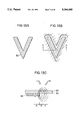
- FIG. 13A is a top plan view of an example of a magnet for forming a V shaped pattern according to the present invention.
- FIG. 13B is a top plan view of the V shaped pattern formed by the magnet shown in FIG. 13A
- FIG. 13C is a partial cross sectional view along X--X line indicated in FIG. 13B.
- FIG. 14A is a schematic top plan view of an example of a magnet for forming a circular shaped pattern according to the present invention
- FIG. 14B is a top plan view of the circular shaped pattern formed by the magnet shown in FIG. 14A.
- FIG. 15A is a top plan view of an example of a wheel cover with desired patterns formed according to the present invention
- FIG. 15B is a cross sectional view along A--A line indicated in FIG. 15A.
- FIG. 16A is a top plan view of magnets to be used in forming the desired patterns on the wheel cover shown in FIGS. 15A and 15B
- FIG. 16B is a cross sectional view along B--B line indicated in FIG. 16A.
- FIG. 17 is a schematic cross sectional view of an apparatus for forming a paint layer on the wheel cover shown in FIGS. 15A and 15B.
- FIG. 18A is a top plan view of another example of a wheel cover with desired patterns formed according to the present invention
- FIG. 18B is a cross sectional view along C--C line indicated in FIG. 18A.
- FIG. 19 is a schematic cross sectional view of an apparatus for forming a paint layer on the wheel cover shown in FIGS. 18A and 18B.
- FIG. 20 is a top plan view of magnets to be used in forming the desired patterns on the wheel cover shown in FIGS. 18A and 18B.
- FIG. 21A is a top plan view of a desired nut shaped pattern to be formed on the wheel cover shown in FIGS. 18A and 18B
- FIG. 21B is a diagram indicating the colors in which various parts of the desired nut shaped pattern shown in FIG. 21A appear
- FIG. 21C is a diagram indicating typical orientations of magnetic flakes at various parts of the desired nut shaped pattern shown in FIG. 21A
- FIG. 21D is a cross sectional view along D--D line indicated in FIG. 21A.
- FIG. 22 is an enlarged cross sectional view of an edge portion of the magnet used in forming the desired nut shaped pattern shown in FIG. 21A, indicating locations at which the lines of magnetic force are parallel to the surface of the paint layer.
- FIG. 23 is a graph of the measured locations at which the lines of magnetic force are parallel to the surface of the paint layer.
- FIG. 24 is a cross sectional view of the magnet used in forming the desired nut shaped pattern shown in FIG. 21A, indicating desired size of the magnet in relation to the thickness of the product body.
- FIG. 25 is a schematic cross sectional view of an alternative arrangement of the magnet used in forming the desired nut shaped pattern shown in FIG. 21A.
- FIG. 26 is a schematic cross sectional view of an apparatus for forming a paint layer on the wheel cover shown in FIGS. 18A and 18B, adopting the alternative arrangement of the magnet shown in FIG. 25.
- FIG. 27A is a top plan view of a desired pattern in a shape of arabic numeral figure "1" to be formed on the product
- FIG. 27B is a cross sectional view along E'--E' line indicated in FIG. 27B
- FIG. 27C is a diagram indicating typical orientations of magnetic flakes at various parts of the desired pattern shown in FIG. 27A
- FIG. 27D is a diagram indicating the colors in which various parts of the desired pattern shown in FIG. 27A appear.
- FIG. 28 is a schematic cross sectional view of an apparatus for forming a paint layer on the product with the desired pattern shown in FIG. 27A.
- FIG. 29 is a perspective view of a magnet to be used in forming the desired pattern shown in FIG. 27A.
- FIG. 30 is a schematic cross sectional view of an alternative arrangement of the magnet used in forming the desired pattern shown in FIG. 27A.
- FIG. 31 is a perspective view of a magnet assembly to be used in forming the desired pattern in a shape of alphabetical letter figure "E" to be formed on the product.
- FIG. 32 is a perspective view of a magnet to be used in forming the desired ring shaped pattern to be formed on the product.
- FIG. 33 is a schematic cross sectional view of an apparatus for forming a paint layer on the product with various desired pattern shown in FIG. 34B.
- FIG. 34A is a diagram indicating the colors in which various parts of the desired pattern shown in FIG. 34B appear
- FIG. 34B is a top plan view of an example of a desired pattern to be formed on the product by using two magnets
- FIG. 34C is a cross sectional view along F--F line indicated in FIG. 34B.
- FIGS. 35A and 35B are mutually corresponding enlarged views of a main portion in FIGS. 34A and 34C.
- FIG. 36A is a diagram indicating the colors in which various parts of a pattern shown in FIG. 36B appear
- FIG. 36B is a top plan view of a pattern to be formed on the product by using only one magnet
- FIG. 36C is a cross sectional view along G--G line indicated in FIG. 36B.
- FIG. 37A is a diagram indicating the colors in which various parts of the desired pattern shown in FIG. 37B appear
- FIG. 37B is a top plan view of another example of a desired pattern to be formed on the product by using two magnets
- FIG. 37C is a cross sectional view along H--H line indicated in FIG. 37B.
- FIG. 38A is a diagram indicating the colors in which various parts of the desired pattern shown in FIG. 38B appear
- FIG. 38B is a top plan view of an example of a desired pattern to be formed on the product by using a magnet and a magnetic field adjustment member
- FIG. 38C is a cross sectional view along J--J line indicated in FIG. 38B.
- FIG. 39A is a diagram indicating the colors in which various parts of a pattern shown in FIG. 39B appear
- FIG. 39B is a top plan view of a pattern to be formed on the product by using a magnet alone
- FIG. 39C is a cross sectional view along K--K line indicated in FIG. 39B.
- FIG. 40A is a diagram indicating the colors in which various parts of the desired pattern shown in FIG. 40B appear
- FIG. 40B is a top plan view of another example of a desired pattern to be formed on the product by using two magnets
- FIG. 40C is a cross sectional view along L--L line indicated in FIG. 40B.
- FIG. 41A is a diagram indicating the colors in which various parts of a pattern shown in FIG. 41B appear
- FIG. 41B is a top plan view of another pattern to be formed on the product by using only one magnet
- FIG. 41C is a cross sectional view along M--M line indicated in FIG. 41B.
- FIG. 42A is a top plan view of a product with the desired pattern formed thereon, whose cross section had been microscopically observed
- FIG. 42B is a cross sectional view of a product and a magnet during the formation of the desired pattern shown in FIG. 42A.
- FIG. 43A is a perspective view of a sample for microscope observation prepared from the product shown in FIG. 42A
- FIG. 43B is an enlarged partial perspective view of the sample shown in FIG. 43A, indicating locations at which the microscope observation of the cross section of the sample shown in FIG. 43A had been made.
- FIG. 44 is a table summarizing the result of the microscope observation of the cross section of the sample shown in FIG. 43A.
- FIG. 45A is a photomicrographic image taken at a location L0 indicated in FIG. 43B
- FIG. 45B is a diagram for explaining the photomicrographic image shown in FIG. 45A.
- FIG. 46A is a photomicrographic image taken at a location L1 indicated in FIG. 43B
- FIG. 46B is a diagram for explaining the photomicrographic image shown in FIG. 46A.
- FIG. 47A is a photomicrographic image taken at a location L2 indicated in FIG. 43B
- FIG. 47B is a diagram for explaining the photomicrographic image shown in FIG. 47A.
- FIG. 48A is a photomicrographic image taken at a location L3 indicated in FIG. 43B
- FIG. 48B is a diagram for explaining the photomicrographic image shown in FIG. 48A.
- FIG. 49A is a photomicrographic image taken at a location L4 indicated in FIG. 43B
- FIG. 49B is a diagram for explaining the photomicrographic image shown in FIG. 49A.
- FIG. 50A is a photomicrographic image taken at a location L5 indicated in FIG. 43B
- FIG. 50B is a diagram for explaining the photomicrographic image shown in FIG. 50A.
- FIG. 51A is a photomicrographic image taken at a location L6 indicated in FIG. 43B
- FIG. 51B is a diagram for explaining the photomicrographic image shown in FIG. 51A.
- FIG. 52A is a photomicrographic image taken at a location L7 indicated in FIG. 43B
- FIG. 52B is a diagram for explaining the photomicrographic image shown in FIG. 52A.
- FIG. 53A is a photomicrographic image taken at a location L8 indicated in FIG. 43B
- FIG. 53B is a diagram for explaining the photomicrographic image shown in FIG. 53A.
- FIG. 54A is a photomicrographic image taken at a location L9 indicated in FIG. 43B
- FIG. 54B is a diagram for explaining the photomicrographic image shown in FIG. 54A.
- FIG. 55A is a photomicrographic image taken at a location L10 indicated in FIG. 43B
- FIG. 55B is a diagram for explaining the photomicrographic image shown in FIG. 55A.
- FIG. 1 there is provided a product 11 to be painted, which is made of a non-magnetic material such as plastic.
- a magnet 13 such as a permanent magnet which is manufactured in advance in such a shape that the magnetic field corresponding to the desired pattern to be formed on the product 11 is produced on the product 11.
- the magnet 13 has an N pole on an upper side directly below the product 11 and an S pole on a lower side, and the magnetic field lines due to this magnet 13 are depicted by dashed lines.
- the magnetic field lines are directed to be substantially perpendicular to the surface of a paint layer 15 to be formed on the surface of the product 11, while in a region B adjacent to the region A, the magnetic field lines changes their directions abruptly, such that they are directed to be substantially parallel to the surface of the paint layer 15 to be formed on the surface of the product 11 in a middle of the region B.
- the magnetic field lines are directed to be uniformly oblique to the surface of the paint layer 15 to be formed on the surface of the product 11.
- the paint layer 15 is formed by the spray painting of a paint mixture prepared in advance which comprises a paint medium, which is preferably transparent, in fluid state in which a multiplicity of tiny non-spherical particles of magnetic bodies 17 (referred hereafter as magnetic flakes), which are preferably made of iron, nickel, cobalt, or their alloys, although any magnetic non-spherical particles can be used, are mixed uniformly by using a volatile solvent.
- the paint layer 15 may be semi-transparent or colored in white, yellow, or any other desired pale color in order to provide the background in the desired pale color on the surface of the painted product.
- each of the magnetic flakes 17 in the paint layer 15 are oriented along its orientation angle ⁇ determined according to the magnetic field due to the magnet 13, and then maintained and eventually fixed in that orientation angle ⁇ by the surrounding transparent paint medium.
- the density of the magnetic flakes 17 in the paint layer 15 depends on the spray speed used in the spray painting of the painting mixture, as well as the magnetic flux density of the magnetic field produced by the magnet 13.
- the magnetic flakes 17 in the region A are oriented to be substantially perpendicular to the paint layer 15 formed on the surface of the product 11, while the magnetic flakes 17 in a middle of the region B are oriented to be substantially parallel to the surface of the paint layer 15 formed on the surface of the product 11.
- the magnetic flakes 17 in the region C are oriented to be uniformly oblique to the surface of the paint layer 15 formed on the surface of the product 11, while the magnetic flakes 17 in the region D are oriented at random as the magnetic field strength becomes significantly weaker in the region D.
- a top coat layer 19 is formed by the spray painting of another transparent paint medium which does not contain any tiny flakes of the magnetic bodies 17.
- the top coat layer 19 may be colored in any desired color in order to provide the background in the desired color on the surface of the painted product.
- FIGS. 2A to 2D show a case in which the paint layer 15 are painted in three layers produced by moving the spray gun three times over the surface of the product 11.
- the magnetic flakes 17 can be oriented more regularly as the transparent paint medium accompanying with the magnetic flakes 17 can be limited.
- FIGS. 2A to 2D show a case in which the surface of the product 11 is colored in gray and the magnetic flakes 17 are made from nickel which are usually colored in silver white.
- the magnetic flakes 17 are oriented to be substantially perpendicular to the surface of the paint layer 15 formed on the surface of the product 11 as shown in FIG. 2A, so that most of the light rays incident from the upper side of the product 11 are either passed through the paint layer 15 or absorbed in the product 11, so that there is very little reflection from the surface of the product 11 in this region A and consequently this region A appears to be colored darker than gray when viewed from the upper side of the product 11.
- the magnetic flakes 17 are oriented to be substantially parallel to the surface of the paint layer 15 formed on the surface of the product 11 as shown in FIG. 2B, so that most of the light rays incident from the upper side of the product 11 are reflected by the magnetic flakes 17, and consequently this region B appears to be colored lighter than gray when viewed from the upper side of the product 11.
- this region B appears almost in white as the magnetic flakes 17 made of nickel are colored in silver white.
- this region B can be made to appear in gold by coating each of the magnetic flakes 17 by a coating material colored in gold in advance.
- the magnetic flakes 17 are oriented to be uniformly oblique to the surface of the paint layer 15 formed on the surface of the product 11 as shown in FIG. 2C, so that the light rays incident from a left upper side L of the product 11 are reflected by the magnetic flakes 17 while the light rays incident from a right upper side of the product 11 are passed through or absorbed by the product 11. Consequently, this region C appears to be colored lighter than gray when viewed from the left upper side L of the product 11 whereas this region C appears to be colored darker than gray when viewed from the right upper side R of the product 11.
- the magnetic flakes 17 are oriented at random as shown in FIG. 2D, so that light rays incident from the upper side of the product 11 are scattered in random directions, and consequently this region D appears to be colored in gray.
- the product which is to be painted prefferably be made from a non-magnetic material such as plastic or aluminum, but it is also possible for the product to be painted to be made from a magnetic material, such as a ferromagnetic material, e.g., iron or an alloy containing iron.
- a magnetic material such as a ferromagnetic material, e.g., iron or an alloy containing iron.
- the shape of the product to be painted is basically unlimited, except that the thickness of the portion to be painted should be thin enough for the magnetic field produced by the magnet placed on the back side of the product to control the orientation of the magnetic flakes contained within the paint layer formed on the front side of the product.
- the product is thicker, as explained hereinafter, then the magnet can be placed on the front side of the product to control orientation. Accordingly, thicker products of any shape can also be used.
- each magnetic flake it is preferable for each magnetic flake to have a flake-like thin plate shape.
- the shape of the flat plane in the flake-like thin plate shape of each magnetic flake is basically unlimited.
- the multiplicity of tiny magnetic bodies to be mixed in the paint medium are described as "magnetic flakes" in the description of the preferred embodiments, in general, the multiplicity of tiny magnetic bodies to be mixed in the paint mixture can take on any non-spherical particle shapes.
- any known magnetic flakes in any known size can be used. It is preferable to use magnetic flakes made of ferromagnetic material such as iron, nickel, cobalt, or their alloys, which can easily be magnetized by the externally applied magnetic field. However, it is also possible to use magnetic flakes made of diamagnetic material such as bismuth, antimony, copper, and zinc. Moreover, the magnetic flakes may be coated with various coatings, including with gold plating or silver plating, or colored by non-magnetic colored paint. Furthermore, the magnetic flakes can be non-magnetic flakes which have been coated with a magnetic coating. It is preferable for each magnetic flake to have a size of about 0.1 to about 1.0 ⁇ m in thickness, and about 10 to about 100 ⁇ m or more preferably about 15 to about 25 ⁇ m in length.
- the paint medium to be used in the paint mixture any medium capable of transmitting light can be used. It is preferable that the medium contain a resin or mixture of resins which can be dried or hardened by reaction at room temperature. It is also possible to use as the medium one which can be hardened by heating or ultraviolet radiation. For example, one or more of alkyd resins, polyester resins, acrylic resins, polyurethane resins, or vinyl resins can be used for the paint medium.
- the medium preferably contains a solvent for the resin.
- the solvent generally, either an organic solvent or water can be used.
- a volatile solvent can also be used in the medium.
- the volatile solvent it is preferable to use a solvent which is both volatile as well as dilutable, such as a thinner.
- faster drying of the medium can be achieved by increasing the amount of the solvent with low boiling point such as methyl ethyl ketone (MEK).
- MEK methyl ethyl ketone
- the paint medium When the paint medium is one which can be hardened by heating, it is necessary to heat the painted product after the magnetic flakes are fixed within the paint layer, by the application of heat, for example, from a heated air blow or infrared radiation.
- the paint medium When the paint medium is one which can be hardened by ultraviolet radiation, it is necessary to apply the UV radiation to the painted product by using ultraviolet radiation from, for example, a mercury lamp.
- the magnetic flakes may be mixed in the paint medium in any desired amount depending upon the desired pattern to be formed. It is preferable for the paint mixture to have the mixture rate of about 1 to about 60 parts by weight of the magnetic flakes per 100 parts by weight of the vehicle, or more preferably the mixture rate of 30 to 40 parts by weight of the magnetic flakes per 100 parts by weight of the vehicle.
- paint used throughout the specification refers to the coating containing the magnetic non-spherical particles. This "paint” may optionally contain other additives, for example, additives which give the desired color to the painted product.
- the apparatus for carrying out the spray painting of the paint mixture can be realized by using conventionally available spray painting apparatus.
- the painting of the paint mixture can be realized by painting methods other than spraying, such as dipping and flow coating.
- top coat layer which does not contain any magnetic flakes, on top of the paint layer containing the magnetic flakes.
- the top coat layer may contain various additives, including colorants which provide the product with the desired color and appearance.
- the paint layer of the present invention can be applied to diversely different types of products, such as glass products (including not only plate glasses but also those having curved surface such as tumblers), plastic products (such as front panels or casings for electric appliances and furniture), vinyl products (including not only the hard vinyl products but also soft vinyl products), wooden panel products, paper products (such as a cardboard boxes), products made by aluminum or aluminum alloy, as well as products made by magnetic material such as iron or steel (such as outer frames of automobiles and refrigerators).
- glass products including not only plate glasses but also those having curved surface such as tumblers
- plastic products such as front panels or casings for electric appliances and furniture
- vinyl products including not only the hard vinyl products but also soft vinyl products
- wooden panel products such as a cardboard boxes
- products made by aluminum or aluminum alloy such as well as products made by magnetic material such as iron or steel (such as outer frames of automobiles and refrigerators).
- the basic principle of the present invention described above can be reversed in a sense that the magnetic flakes can be utilized for absorbing the light rays rather than reflecting the light rays as described above. Namely, by coating each of the magnetic flakes in the paint mixture with a surface coating having a dark color such as black or by using magnetic flakes which have a dark color such as black, the desired pattern can be formed as the magnetic flakes oriented to be substantially parallel to the surface of the paint layer absorb the light rays incident on the paint layer such that the desired pattern formed by these magnetic flakes appears as colored in black in contrast to the surrounding regions appearing as colored in gray.
- FIGS. 3 to 10 various exemplary configurations for the magnet to be used in the procedure described above will be described.
- the configuration shown in FIG. 3 is a configuration for forming the magnetic field lines which are substantially parallel to the surface of the paint layer 15 to be formed on the surface of the product 11, which is formed by an electromagnet 21 having a gap between its N and S poles located on the upper surface of the product 11.
- an electromagnet 21 having a gap between its N and S poles located on the upper surface of the product 11.
- a mask 23 having a window in a shape corresponding to a desired pattern to be formed on the surface of the product 21.
- the configuration of FIG. 4 is another configuration for forming the magnetic field lines which are substantially parallel to the surface of the paint layer 15 to be formed on the surface of the product 11, which is also formed by the electromagnet 21.
- the electromagnet 21 is placed below the lower surface of the product 11, with the gap between its N and S poles located directly below the lower surface of the product 11.
- the mask 23 similar to that used in the configuration of FIG. 3 is also provided above the upper surface of the product 11 in this configuration of FIG. 4, so that the spray painting of the paint mixture as described above is applied from the upper side of the mask 23, just as in the case of FIG. 3.
- the configuration of FIG. 5 is a configuration for forming the magnetic field lines which are substantially perpendicular to the surface of the paint layer 15 to be formed on the surface of the product 11.
- an electromagnet 25 having its N and S poles on its opposite ends is placed below the lower surface of the product 11 with the N pole located directly below the lower surface of the product 11.
- the mask 23 similar to that used in the configuration of FIG. 8 is also provided above the upper surface of the product 21 in this configuration of FIG. 5, so that the spray painting of the paint mixture as described above is applied from the upper side of the mask 23, just as in the case of FIG. 3.
- the configuration of FIG. 6 is a configuration for forming the magnetic field lines which are oblique to the surface of the paint layer 15 to be formed on the surface of the product 11.
- an electromagnet 29 having its N and S poles on its opposite ends with the end of the N pole formed in an oblique surface is placed below the lower surface of the product 11 with the N pole located directly below the lower surface of the product 11.
- the mask 23 similar to that used in the configuration of FIG. 3 is also provided above the upper surface of the product 11 in this configuration of FIG. 6, so that the spray painting of the paint mixture as described above is applied from the upper side of the mask 23, just as in the case of FIG. 3.
- the configuration of FIG. 7 is a configuration for forming the magnetic field lines which are substantially parallel to the surface of the paint layer 15 to be formed on the surface of the product 11 by using a permanent magnet.
- a plate shaped permanent magnet 33 having its N and S poles on its opposite ends is placed directly below the lower surface of the product 11.
- the mask 23 similar to that used in the configuration of FIG. 3 is also provided above the upper surface of the product 11 in this configuration of FIG. 7, so that the spray painting of the paint mixture as described above is applied from the upper side of the mask 23, just as in the case of FIG. 3.
- the configuration of FIG. 8 is another configuration for forming the magnetic field lines which are substantially parallel to the surface of the paint layer 15 to be formed on the surface of the product 11 by using a permanent magnet.
- two plate shaped permanent magnets 37a and 37b each of which having its N and S poles on its opposite ends are placed directly above the upper surface of the product 11 with the N pole of one magnet 37a facing against the S pole of another magnet 37b.
- the mask 23 similar to that used in the configuration of FIG. 3 is also provided above the upper surface of the product 11 in this configuration of FIG. 8, so that the spray painting of the paint mixture as described above is applied from the upper side of the mask 23, just as in the case of FIG. 3.
- the configuration of FIG. 9 is another configuration for forming the magnetic field lines which are substantially perpendicular to the paint layer 15 to be formed on the surface of the product 11 by using a permanent magnet.
- a plate shaped permanent magnet 41 having its N and S poles on its upper and lower faces are placed directly below the lower surface of the product 11 with the N pole side facing against the lower surface of the product 11.
- the mask 23 similar to that used in the configuration of FIG. 3 is also provided above the upper surface of the product 11 in this configuration of FIG. 9, so that the spray painting of the paint mixture as described above is applied from the upper side of the mask 23, just as in the case of FIG. 3.
- the configuration of FIG. 10 is a configuration for forming the magnetic field lines which are oblique to the surface of the paint layer 15 to be formed on the surface of the product 11 by using a permanent magnet.
- a plate shaped permanent magnet 45 having its N and S poles on its upper and lower faces is attached to a ferromagnetic block 47 having an oblique surface and this ferromagnetic block 47 is placed directly below the lower surface of the product 21 with its oblique surface facing against the lower surface of the product 11.
- the mask 23 similar to that used in the configuration of FIG. 3 is also provided above the upper surface of the product 11 in this configuration of FIG. 10, so that the spray painting of the paint mixture as described above is applied from the upper side of the mask 23, just as in the case of FIG. 3.
- FIGS. 11A, 11B, 12A, and 12B exemplary cases of forming a line figure pattern by the procedure described above will be described.
- FIGS. 11A and 11B show a case of forming a square shaped line figure on a product 53 by using a permanent magnet plate 51 having its N and S poles on its upper and lower faces,respectively, is placed directly below the lower surface of the product 53 with the N pole side facing against the lower surface of the product 53.
- the magnet plate 51 is manufactured as a thin strip in a shape corresponding to the desired pattern to be formed, i.e., a square shaped line figure, as shown in FIG. 11A.
- the spray painting of the paint mixture as described above is applied to an upper surface of the product 53 such that the paint layer 61 is formed on the upper surface of the product 53.
- the magnetic field lines are substantially perpendicular to the surface of the paint layer 61 in a region A, while the magnetic field lines are substantially parallel to the surface of the paint layer 81 in regions B and C.
- the region A appears as colored in black while the regions B and C appear as colored in white, as described above in conjunction with FIGS. 2A to 2D, so that the square shaped line figure with sides of the square which appear to be concave can be formed on the surface of the product 53.
- FIGS. 12A and 12B show a complementary case of the case shown in FIGS. 11A and 11B, in which a complementary square shaped line figure is to be formed on a product 53 by using a permanent magnet plate 55 having its N and S poles on its upper and lower faces, respectively, is placed directly below the lower surface of the product 53 with the N pole side facing against the lower surface of the product 53.
- the magnet plate 55 is manufactured as a flat plate with a thin strip puncture 57 in a shape corresponding to the desired pattern to be formed, i.e., a square shaped line figure, as shown in FIG. 12A.
- the spray painting of the paint mixture as described above is applied to an upper surface of the product 53 such that the paint layer 61 is formed on the upper surface of the product 53.
- the magnetic field lines are substantially parallel to the surface of the paint layer 61 in a region A, while the magnetic field lines are substantially perpendicular to the surface of the paint layer 61 in regions B and C.
- the region A appears as colored in white while the regions B and C appear as colored in black, as described above in conjunction with FIGS. 2A to 2D, SO that the square shaped line figure with sides of the square which appear to be convexed can be formed on the surface of the product 53.
- FIGS. 13A, 13B, 13C, 14A, and 14B exemplary cases of forming a plane figure pattern by the procedure described above will be described.
- FIGS. 13A, 13B, and 13C show a case of forming a V shaped plane figure on a product 54 by using a permanent magnet plate.
- the plane magnet plate 52 having its N and S poles on its upper and lower faces, respectively, is placed directly below the lower surface of the product 54 with the N pole side facing against the lower surface of the product 54.
- the magnet plate 52 is manufactured in a shape corresponding to the desired pattern to be formed, i.e., a V shaped plane figure, as shown in FIG. 13A.
- the spray painting of the paint mixture as described above is applied to an upper surface of the product 54 such that the paint layer 62 is formed on the upper surface of the product 54.
- the magnetic field lines are substantially perpendicular to the surface of the paint layer 82 in a region A which is directly below the V shaped plane figure, while the magnetic field lines are substantially parallel to the surface of the paint layer 82 in a region B which is at a contour of the V shaped plane figure, and the magnetic field lines are oblique to the surface of the paint layer 62 in a region C which is further distanced from the V shaped plane figure than the region B.
- the region A appears as colored in black while the region B appears as colored in white, as described above in conjunction with FIGS. 2A to 2D, so that the V shaped plane figure with the contour of the V shape appear to be convexed can be formed on the surface of the product 54, as shown in FIG. 13B.
- the orientations of the magnetic flakes in the region B are continuously changed to the oblique directions toward the region C, so that the convexed V shape appear to have a smoothly round edge.
- the magnetic flakes in the paint layer 62 are oriented to be oblique to the surface of the paint layer 62 formed on the surface of the product 54 as shown in FIG. 13C, so that this region C appears to be colored in black when viewed from the left upper side L of the product 54 whereas this region C appears to be colored in white when viewed from the right upper side R of the product 54. Consequently, when viewed from the left upper side L, only the region B in a shade of the contour of the V shaped plane figure appears as convexed, whereas when viewed from the right upper side R, only the region A in a shape of the V shaped plane figure itself appears as concave.
- the magnetic flakes in the paint layer 62 are oriented at random as the magnetic field strength decreases in inverse proportion to the square of the distance from the magnet plate 52, so that light rays incident from the upper side of the product 54 are scattered in random directions, and consequently this region appears to be colored in the same color as the surface of the product 54 itself.
- FIGS. 14A and 14B show a case of forming a circular shaped plane figure on a product 58 by using a permanent; magnet plate.
- the plane magnet plate 56 having its N and S poles on its upper and lower faces, respectively, is placed directly below the lower surface of the product 56 with the N pole side facing against the lower surface of the product 58.
- the magnet plate 58 is manufactured to have a puncture in a shape corresponding to the desired pattern to be formed, i.e., a circular shaped plane figure, as shown in FIG. 14A.
- the spray painting of the paint mixture as described above is applied to an upper surface of the product 58 such that the paint layer is formed on the upper surface of the product 58.
- the magnetic field lines are substantially perpendicular to the surface of the paint layer in a region A which is directly above the magnet plate 56, while the magnetic field lines are substantially parallel to the surface of the paint layer in a region B which is at a contour of the circular shaped plane figure, and the magnetic field lines are oblique to the surface of the paint layer at an edge of a region C which is an interior of the circular shaped plane figure and become weaker inward.
- the regions A and C appear as colored in black while the region B appears as colored in white, as described above in conjunction with FIGS. 2A to 2D, so that the circular shaped plane figure with the contour of the circular shape appear to be convexed can be formed on the surface of the product 58, as shown in FIG. 14B.
- the region C can be made to contain only the obliquely oriented magnetic flakes, such that the interior of the circular shaped plane figure may also appear as colored in white when viewed from the oblique direction.
- FIGS. 15A, 15B, 16A, 16B, and 17 one example of application of the present invention to an automobile wheel cover will be described.
- a disk shaped automobile wheel cover 71 made of a plastic material has a plan view as shown in FIG. 15A and a view from A--A cross section in FIG. 15A as shown in FIG. 15B, and on the surface of this wheel cover 71, V shaped patterns 73 and circular patterns 75 are to be formed by using the present invention.
- the magnet to be used in forming the patterns has a configuration with a plan view as shown in FIG. 16A and a view from B--B cross section in FIG. 16A as shown in FIG. 16B, in which V shaped permanent magnets 83 and circular shaped permanent magnets 85 made of rubber containing ferrite are arranged in correspondence to the V shaped patterns 73 and the circular shaped patterns 75 to be formed, on a magnet support member 87 made of a non-magnetic material such as wood or plaster.
- the wheel cover 71 and the magnet support member 87 are mounted on a wheel cover support member 79 which is provided on a base 77 to be freely rotatable, such that the permanent magnets 83 and 85 arranged on the magnet support member 87 faces against the back side of the wheel cover 71.
- the spray painting of a paint mixture is applied by a spray gun 91, while the wheel cover support member 79 is rotated at a constant speed, such that a plurality of thin paint layers are uniformly formed on the surface of the wheel cover 71.
- the paint mixture used in the spray painting comprises a transparent paint medium in fluid state in which a multiplicity of magnetic flakes made of nickel are mixed uniformly by using a volatile solvent.
- the paint mixture is further mixed with a thinner for the purpose of faster drying and easy spraying due to the reduced viscosity.
- the wheel cover 71 After waiting for approximately ten to one hundred seconds since the completion of the spray painting, the wheel cover 71 is taken off the wheel cover support member 79 and the paint layers formed on the surface of the wheel cover 71 are dried.
- FIGS. 18A and 18B another example of an application of the present invention to an automobile wheel cover will be described in detail.
- a disk shaped automobile wheel cover 101 manufactured from a plastic material by injection molding has a plan view as shown in FIG. 18A and a view from C--C cross section in FIG. 18A as shown in FIG. 18B.
- This wheel cover 101 has: eight attachment hooks 103 along its circumference on the back side of the wheel cover 101, by means of which the wheel cover 101 is to be attached to a road wheel of the automobile; eight air holes 105 connecting the front and back sides of the wheel cover 101, which are located at inner side of the attachment hooks 103; and a central protrusion 109 located at a center of the back side of the wheel cover 101, which is formed at a resin injection part in an injection mold used in manufacturing the wheel cover 101.
- This central protrusion 109 is used for mounting the wheel cover 101 on the painting apparatus during the painting process, and will be cut off after the painting process is over.
- the wheel cover 101 as a whole is formed in a convexed shape such that its front surface is a partial spherical surface which is substantially flat locally.
- to be substantially flat locally means it is curved by a radius of curvature greater than 100 mm.
- the entire front surface of the wheel cover can be regarded as flat in effect, except for the edges of the air holes 105.
- four nut shaped patterns 107 are arranged to be symmetric with respect to the center P of the circle on which the nut shaped patterns 107 are arranged, such that the disturbance of the formed nut shaped patterns 107 due to the interference of the magnetic field for forming one of the nut shaped patterns 107 and the magnetic fields for forming other ones of the nut shaped patterns 107 can appear symmetrically in the nut shaped patterns as a whole.
- This apparatus of FIG. 19 comprises: a base frame 111; a support member 121, made of wood or plaster and fixed on the base frame 111, for supporting the back side of the wheel cover 101 mounted thereon, which has a conical guide hole 113 at a center; a vertically movable holding member 116 having an air cylinder 130 for moving the holding member 116 in the vertical direction and a holding device 118 located inside the guide hole 113 for holding the central protrusion 109 of the wheel cover 101 to be movable in the vertical direction; and magnets 119 for forming the desired pattern on the wheel cover 101 during the painting process, which are mounted on magnet mounting holes 121a provided on the top surface of the support member 121 at locations corresponding to the desired nut shaped patterns to be formed.
- the desired nut shaped patterns 107 can be formed on the wheel cover 101 by the following procedure.
- the wheel cover 101 is mounted on the top surface of the support member 121 by inserting the central protrusion 109 into the holding device 118, and then pulling the holding member 116 downward by means of the air cylinder 130 so as to contact the back side of the wheel cover 101 tightly against the top surface of the support member 121.
- the front surface of the wheel cover 101 is placed inside the magnetic fields produced by the magnets 119 having the lines of magnetic force corresponding to the shapes of the desired nut shaped patterns to be formed.
- the paint layer is formed uniformly on the front surface of the wheel cover 101 by the spray painting from a spray gun 131 of the paint mixture 133 prepared from the paint medium with the magnetic flakes uniformly mixed by using a volatile solvent, such that the desired nut shaped patterns 107 can be formed on the paint layer as the magnetic flakes in the paint layer change their orientations according to the lines of magnetic force due to the magnetic fields produced by the magnets 119, according to the principle of the present invention as described above.
- the wheel cover 101 After waiting for the volatile solvent in the paint mixture 133 to volatilize such that the orientations of the magnetic flakes can be fixed in the paint layer, the wheel cover 101 is dismounted from the support member 121 and the paint layer is fully solidified by using an appropriate solidification method.
- FIG. 21A shows a relationship between the shapes of the magnet 119 and the nut shaped pattern 107 formed by the magnet 119.
- the nut shaped pattern 107 has the hexagonal outer contour 149a and a circular inner contour 149b.
- the outer and inner contours 149a and 149b of the nut shaped pattern 107 actually have predetermined widths and solid lines depicted in FIG. 21A indicate the ridge portions 149 of the outer and inner contours 149a and 149b which appear most whitish within the outer and inner contours 149a and 149b appearing as colored in white.
- FIG. 21B indicates the color in which different parts of the nut shaped pattern 107 along D--D line depicted in FIG. 21A appear, where the middle line corresponds to the gray color of the wheel cover 101 itself, and those portions above the middle line appear as colored in white and convexed in contrast to the surrounding portions, while those portions below the middle line appear as colored in black and concave in contrast to the surrounding portions.
- FIG. 21C depicts the typical orientations of the magnetic flakes at different parts of the nut shaped pattern 107 along D--D line depicted in FIG. 21A.
- those portions which appear as colored in white have the magnetic flakes oriented to be substantially parallel to the surface of the paint layer
- those portions which appear as colored in black have the magnetic flakes oriented to be substantially perpendicular to the surface of the paint layer
- those portions which appear as colored in gray have the magnetic flakes oriented to be oblique to the surface of the paint layer or at random.
- FIG. 21D shows the lines of magnetic force 139 due to the magnetic fields produced by the magnet 119 through the wheel cover 101 and the paint layer 115 formed thereon.
- the hexagonal outer contour 149a and the circular inner contour 149b of the nut shaped pattern 107 are located at positions where the lines of magnetic force 139 are oriented to be substantially parallel to the surface 137 of the paint layer 115 at which the magnetic flakes 117 in the paint layer 115 along these lines of magnetic force 139, and the ridge portions 149 of the nut shaped pattern 107 are located at centers of the outer and inner contours 149a and 149b at which the lines of magnetic force 129 are oriented to be parallel to the surface 137 of the paint layer.
- the locations P 1 , P 2 , P 3 , etc. at which the lines of magnetic force 139 are oriented to be parallel to the surface 137 of the paint layer 115 were measured to be located in relation to the magnet 119 as shown in FIG. 22.
- the position in the X direction at which the ridge portion of the contour of the desired pattern is formed is located at 0.2 mm away from the edge of the magnet 119.
- the desired pattern in the desired size by manufacturing the magnet 119 to have the size smaller than the desired size by 0.2 mm toward the center of the desired pattern.
- the desired pattern in the desired size by manufacturing the magnet 119 to have the size smaller than the desired size by a predetermined distance determined according to the measurement result shown in FIG. 23, toward the center of the desired pattern.
- FIG. 24 shows a comparison of sizes of the magnets 147a and 147b required in cases of forming the same desired pattern on the products 143a and 143b which have the different thicknesses T1 and T2, respectively.
- each of the magnets 147a and 147b is assumed to have a doughnut like shape with a central bore.
- ⁇ 1 indicates a distance between the edge of the magnet 147a and the ridge portion 149 of the contour of the desired pattern to be formed
- ⁇ 2 indicates a distance between the edge of the magnet 147b and the ridge portion 149 of the contour of the desired pattern to be formed.
- S OUT1 indicates a distance between the center and the outer contour of the magnet 147a
- S OUT2 indicates a distance between the center and the outer contour of the magnet 147b
- S IN1 indicates a distance between the center and the inner contour of the magnet 147a
- S IN2 indicates a distance between the center and the inner contour of the magnet 147b
- L OUT indicates a distance between the center and the ridge portion of the outer contour 149a of the desired pattern to be formed
- L IN indicates a distance between the center and the ridge portion of the inner contour 149b of the desired pattern to be formed.
- ⁇ 1 and ⁇ 2 depend on the thicknesses T1 and T2 of the products 143a and 143b.
- the magnet in general, it is possible to obtain the desired pattern in the desired size by manufacturing the magnet to have the size of the contour smaller than the ridge portion of the contour of the desired pattern to be formed, such that the positions at which the lines of magnetic force due to the magnetic field produced by the magnet can be located at the positions of the ridge portion of the contour of the desired pattern to be formed.
- the size of the contour of the magnet to be used in forming the desired pattern should be made smaller.
- the number of patterns to be formed on the product is not limited to the case of four described above, and any desired number of the patterns can be formed on the product.
- the magnet 119 may be placed on the front side of the product 101 as shown in FIG. 25.
- the appropriate size and position of the magnet 119 for forming the desired pattern on the front surface of the product 101 can be determined by regarding a distance d between the magnet 119 and the surface 137 of the painted layer 115 provided on the front surface of the product 101 as a thickness of an imaginary product to be painted. Consequently, when the magnet is placed on the front side, the position of the magnet 119 with respect to the paint layer 115 is not restricted by the thickness of the product 101.
- FIG. 26 An exemplary configuration of the apparatus for forming the desired patterns on the surface of the wheel cover 101 using such a positioning of the magnet 119 over the front surface of the wheel cover 101 is shown in FIG. 26.
- This apparatus of FIG. 26 differs from that shown in FIG. 19 in that the magnet 119 is located above the front surface of the wheel cover 101 mounted on the support member 121, where the magnet 119 is attached on the back side of an inner lid 146 attached to the base frame by a hinge 138 such that it can be opened up or closed down to a position of a stopper 136, and that there is provided an air supply mechanism formed by an outer lid 145 attached on the inner lid 146 which is equipped with an air supply inlet 151 from which the air or heated air can be supplied into the inner lid 146 through holes 141 provided on an upper side of the inner lid 146, and air outlets 148 provide on lower side portion of the inner lid 146 through which the air supplied from the air supply inlet 151 can escape.
- the paint layer is formed on the front surface of the wheel cover 101 first while the inner lid 146 is opened up, and then the inner lid 146 is closed to form the desired patterns on the paint layer while the air or heated air is supplied from the air supply inlet 151 in order to volatilize the volatile solvent in the paint mixture used in forming the paint layer 115 (not shown).
- FIGS. 27A to 27D an example of application of the present invention for the formation of numeral figure pattern will be described in detail.
- FIG. 27A shows a top plan view of a product 201 with a desired pattern 207 formed thereon, along with a relationship between the shapes of a magnet 215 and the pattern 107 formed by the magnet 215.
- a product 201 has a pattern 207 in a shape of an arabic numeral figure "1" formed by using a magnet 215 having a shape of an arabic numeral figure “1” which is placed on the back side of the product 201.
- FIG. 27B shows the lines of magnetic force 219 due to the magnetic fields produced by the magnet 215 through a product body 203, a paint layer 205 formed by a paint mixture containing magnetic flakes 211, and a transparent top coat layer 205a, along line E'--E' depicted in FIG. 27A.
- FIG. 27C depicts the typical orientations of the magnetic flakes 211 contained in the paint layer 205 at different parts A, B, C, D, and E of the pattern 207 along line E'--E' depicted in FIG. 27A.
- FIG. 27D indicates the color in which different parts A, B, C, D, and E of the pattern 207 along line E'--E' depicted in FIG. 27A appear, where the middle line corresponds to the gray color of the product body 203 itself, and those portions above the middle line appear as colored in white and convexed in contrast to the surrounding portions, while those portions below the middle line appear as colored in black and concave in contrast to the surrounding portions.
- the formation of the pattern 207 on the product 201 can be achieved by forming the paint layer 205 on an upper surface of the product body 203 by spray painting the paint mixture 209 containing the magnetic flakes 211 from a spray gun 204, while the magnet 215 is placed below the lower surface of the product 203 such that the magnetic flakes 211 in the paint layer 205 are oriented along the lines of magnetic force 219 due to magnetic field produced by the magnet 215.
- the magnet 215 having a shape of the arabic numeral figure “1” is prepared by die cutting a block shaped magnet 217 into the shape of the arabic numeral figure “1" in a direction perpendicular to a plane defined by a line joining N and S poles.
- the contour 221 of the region C which appears as colored in white is located at positions inside of the S and N pole side outer contours 215a and 215b of the magnet 215, so that the magnet 215 is prepared to have the size slightly larger than the desired size of the pattern 207 to be formed on the product 201.
- the magnet 215 is located below the lower surface of the product body 203 with the N pole side outer contour 215b facing toward the left side and S pole side outer contour 215a facing toward the right side, such that there is only a single position between the N pole and S pole of the magnet 215 at which the lines of magnetic force 219 due to the magnetic field produced by the magnet 215 are oriented to be parallel to the surface 213 of the paint layer 205. Consequently, the ridge portion of the pattern 207 formed by the magnetic flakes 211 which are oriented to be parallel to the surface 213 of the paint layer 205 in the region C appears as a line figure in a shape of the arabic numeral figure "1".
- the region C in a shape of the arabic numeral figure "1" has the magnetic flakes 211 oriented to be substantially parallel to the surface 213 of the paint layer 205 such that this region C appears as colored in white, while the regions B and D adjacent to the region C have the magnetic flakes 211 oriented to be oblique or perpendicular to the surface 213 of the paint layer 205 such that these regions B and D appear as colored in black.
- the regions A and E located around the regions B and D have the magnetic flakes 211 oriented at random, as the magnetic field strength is negligibly weak in these regions, such that these regions A and E appear as colored in gray.
- the magnet 215 with a line joining the N and S poles arranged parallel to the surface 213 of the paint layer 205 on the back side of the product body 203, it is possible to form the pattern 207 with the ridge portion formed by the magnetic flakes 211 which are oriented to be parallel to the surface 213 of the paint layer 205 appearing as a line figure in a shape of the arabic numeral figure "1".
- the magnet 215 is supported by a magnet support member 225 and positioned above the surface 213 of the paint layer 205 formed on the product body 203, with a line joining the N and S poles arranged parallel to the surface 213 of the paint layer 205, such that it is also possible to form the pattern 207 with the ridge portion formed by the magnetic flakes 211 which are oriented to be parallel to the surface 213 of the paint layer 205 appearing as a line figure in a shape of the arabic numeral figure "1".
- the appropriate size and position of the magnet 215 for forming the desired pattern on the front surface of the product 201 can be determined by regarding a distance between the magnet 201 and the surface 213 of the painted layer 205 provided on the front surface of the product 201 as a thickness of an imaginary product to be painted. Consequently, the position of the magnet 215 with respect to the paint layer 205 is not restricted by the thickness of the product 201.
- This positioning of the magnet 215 above the product 201 is convenient in a case in which it is difficult to place the magnet 215 on the back side of the product 201 appropriately due to the complicated shape of the back side of the product 201 and/or because of the thickness of the product.
- FIG. 31 and FIG. 32 other examples of application of the present invention for the formation of a figure pattern which has more complicated shape than the arabic numeral figure "1" described above will be described in detail.
- the overall shape of the figure pattern is divided into a plurality of segments having relatively simple shape, such that each segment can be formed by using a simple block shaped magnet in a manner similar to the case of forming the arabic numeral figure "1" described above.
- the overall shape of this alphabetical letter figure “E” can be divided into four straight line segments such that these line segments can be formed by the magnet 231 comprising four separate block shaped magnet pieces 231a, 231b, 231c, and 231d, which are to be assembled together in a shape of the alphabetical letter figure "E", as shown in FIG. 31.
- Each of the block shaped magnet pieces 231a, 231b, 231c, and 231d has a line joining the N and S poles arranged parallel to the surface of the paint layer, such that it is also possible to form the corresponding line segment with the ridge portion formed by the magnetic flakes which are oriented to be parallel to the surface of the paint layer.
- the adjacently arranged magnet pieces 231b and 231d, and 231d and 231c have the opposite poles facing against each other.
- the ring shaped planar magnet 233 having the S pole on the inner circumference side and the N pole on the outer circumference side as shown in FIG. 32 can be used.
- this ring shaped planar magnet 233 By placing this ring shaped planar magnet 233 on either the front or back side of the product with a line joining the N and S poles arranged parallel to the surface of the paint layer, it is also possible to form the ring shaped pattern with the circular ridge portion formed by the magnetic flakes which are oriented to be parallel to the surface of the paint layer.
- FIG. 33 other configuration of the magnets for forming the desired pattern on the product according to the present invention, which are suitable for the formation of more complicated patterns will be described in detail.
- the product 301 comprises a product body 303 made of a plastic material which is formed in a substantially flat shape, .and a paint layer 305 formed thereon.
- to be substantially flat means it is curved by a radius of curvature greater than about 100 mm.
- the apparatus for forming the paint layer 305 on the product body 303 in this case has a configuration shown in FIG. 33, which comprises: a base frame 309; a support member 311, made of non-magnetic material such as wood or plaster and fixed on the base frame 309, for supporting the back side of the product 301 mounted thereon, which has magnet mounting holes 317 provided on its upper surface 311a at locations corresponding to the desired patterns to be formed; first and second magnets 313 and 315 for forming the desired pattern on the paint layer 305 formed on the product body 303 during the painting process, which are mounted in the magnet mounting holes 317; a paint mixture container 319 for containing the paint mixture 323 having the magnetic flakes 321 mixed therein; and a spray gun 325 for spray painting the paint mixture contained in the paint mixture container 319 onto the front surface of the product body 303 to form the paint layer 305 uniformly thereon.
- the first and second magnets 313 and 315 have configurations as shown in FIGS. 34B and 34C, where the first magnet 313 is a sheet rubber permanent magnet having an approximately doughnut like shape with a rectangular outer contour 313a and a circular inner contour 313b of a radius equal to R1, while the second magnet 315 is another sheet rubber permanent magnet having a disk like shape with a circular outer contour 315a of a radius equal to R2 (R2 ⁇ R1) which is located inside the circular inner contour 313b of the first magnet 313 concentrically.
- the first magnet 313 has the N pole side facing against the lower surface of the product body 303
- the second magnet 315 has the S pole side facing against the lower surface of the product body 303. This second magnet 315 functions to adjust the magnetic field produced by the first magnet 313 as will be described in detail later.
- the desired pattern can be formed on the product 301 by the following procedure.
- the product 301 prepared by the injection molding and having a front surface colored in yellowing ivory color is mounted on the upper surface 311a of the support member 311 with the first and second magnets 313 and 315 placed in the magnet mounting holes 317.
- the front surface of the product 301 is placed inside the magnetic fields produced by the first and second magnets 313 and 315 having the lines of magnetic force corresponding to the shapes of the desired patterns to be formed.
- the lines of magnetic force 333a in a vicinity of the outer contour 313a of the first magnet 313 are oriented from the N pole side to the S pole side of the first magnet 313 at the paint layer 305
- the lines of magnetic force 333b in a vicinity of the region between the inner contour 313b of the first magnet 313 and the outer contour 315a of the second magnet 315 are oriented from the N pole side of the first magnet 313 to the S pole side of the second magnet 315 at the paint layer 305.
- the positions at which the lines of magnetic force 333a and 333b are oriented to be parallel to the surface of the paint layer 305 correspond to the ridge portions of the contours 327 and 328 of the pattern I shown in FIG. 34B.
- the paint layer 305 is formed uniformly on the front surface of the product 301 by the spray painting from the spray gun 325 of the paint mixture 323 prepared from the paint medium with the magnetic flakes 321 uniformly mixed by using volatile solvent, such that the desired pattern I including the contours 327 and 328 can be formed on the paint layer 305 as the magnetic flakes 321 in the paint layer 305 change their orientations according to the lines of magnetic force 333a and 333b due to the magnetic fields produced by the magnets 313 and 315, according to the principle of the present invention as described above.
- the product 301 is dismounted from the support member 311 and the paint layer 305 is fully solidified by using an appropriate solidification method. Then, the transparent top coat layer 305a is formed on the surface of the paint layer 305 uniformly by the spray painting.
- FIGS. 34A, 34B, and 34C further detail of the formation of the desired pattern I will be described.
- the desired pattern I in this case includes the outer contour 327 and the inner contour 328 which have the widths W1 and W2, respectively.
- FIG. 34A indicates the color in which different parts of the pattern I along F--F line depicted in FIG. 34B appear, where the middle line corresponds to the gray color of the product body 303 itself, and those portions above the middle line appear as colored in white and convexed in contrast to the surrounding portions, while those portions below the middle line appear as colored in black and concave in contrast to the surrounding portions.
- the outer and inner contours 327 and 328 appear as colored in white and convexed, while a region 327a between the outer and inner contours 327 and 328 as well as a region 331 inside the inner contour 328 appear as colored in black and concave, and a region 329 outside of the outer contour 327 appears as colored in gray. Also, as indicated in FIG.
- the portions Whmax which appear most brightly white are located at the ridge portions of the outer and inner contours 327 and 328, while the portions B1max which appear most darkly black are located at middles of the regions 327a and 331. Consequently, the pattern I has the three dimensional perspective as the outer and inner contours 327 and 328 appear as if they are projected out of the surface of the product body 303 while the regions immediately surrounding these outer and inner contours 327 and 328 appear as if they are engraved into the surface of the product body 303, in contrast to the gray background formed by the surface of the product body 303 elsewhere.
- FIGS. 35A and 35B show enlarged views of mutually corresponding main portion in FIGS. 34A and 34C around one part of the inner contour 328, respectively, where the sizes of the magnetic flakes 321 in the paint layer 305 are exaggerated for the purpose of easier comprehension.
- the magnetic flakes 321 in the paint layer 305 are oriented along the lines of magnetic force 333b which are oriented to be parallel to the surface 335 of the paint layer 305, so that the most brightly white part Whmax is formed as the ridge portion at the center of the inner contour 328.
- the magnetic flakes 321 in the paint layer 305 are oriented along the lines of magnetic force 333b which are oriented to be substantially perpendicular to the surface 325 of the paint layer 305, so that these regions 327a and 331 appear as colored in black.
- the magnetic flakes 321 in the paint layer 305 are oriented at random, as the magnetic field strength is negligibly weak there.
- FIGS. 36A to 36C in contrast to FIGS. 34A to 34C described above, the difference between a case of forming the pattern by using two magnets as shown in FIGS. 34A to 34C and a case of forming the pattern by using only one magnet as shown in FIGS. 36A to 36C is described.
- FIGS. 36A to 38C show a case of forming the pattern II including an outer contour 337 and an inner contour 338, which have the widths W3 and W4, respectively, as shown in FIG. 36B, by using only the first magnet 313 as shown in FIG. 36C.
- FIG. 36A indicates the color in which different parts of the pattern II along G--G line depicted in FIG. 36B appear, where the middle line corresponds to the gray color of the product body 303 itself, and those portions above the middle line appear as colored in white and convexed in contrast to the surrounding portions, while those portions below the middle line appear as colored in black and concave in contrast to the surrounding portions.
- the outer and inner contours 337 and 338 appear as colored in white and convexed, while a region between the outer and inner contours 337 and 338 as well as a region inside the inner contour 338 appear as colored in black and concave, and a region outside of the outer contour 337 appears as colored in gray, similarly to the case shown in FIGS. 34A to 34C.
- the lines of magnetic force 339a in a vicinity of the outer contour 313a of the first magnet 313 as well as the lines of magnetic force 339b in a vicinity of the inner contour 313b of the first magnet 313 are oriented from the N pole side to the S pole side of the first magnet 313 at the paint layer 305, in contrast to the lines of magnetic field 333a and 333b shown in FIG. 34C.
- the inner contour 328 has more sharply defined outer and inner edges 328a and 328b compared with outer and inner edges 338a and 338b of the inner contour 338 as can be seen by comparing FIG. 34A and FIG. 36A.
- the width W2 of the inner contour 328 is wider than the width W4 of the inner contour 388.
- the lines of magnetic field 333b are flattened down compared with the lines of magnetic force 339b, such that there are more magnetic flakes 321 located in wider region which are oriented to be substantially perpendicular to the surface of the paint layer 305 in a case shown in FIGS. 34A to 34C.
- the exact value for the width W2 of the inner contour 328 depends on the inner radius R1 of the first magnet 313 and the outer radius R2 of the second magnet 315, where the width W2 is widened as the outer radius R2 of the second magnet 315 becomes smaller whereas the width W2 is narrowed as the outer radius R2 of the second magnet 315 becomes larger, while the inner radius of the first magnet 313 is fixed.
- FIGS. 37A to 37C other configurations of the magnets for forming the desired pattern on the product according to the present invention, which are suitable for the formation of more complicated patterns will be described in detail.
- first and second magnets 313 and 315 have configurations as shown in FIGS. 37B and 37C, where the first magnet 313 has the N pole side facing against the lower surface of the product body 303, while the second magnet 315 also has the N pole side facing against the lower surface of the product body 303.
- the lines of magnetic force 341a in a vicinity of the outer contour 313a of the first magnet 313 are oriented from the N pole side to the S pole side of the first magnet 313 at the paint layer 305, while in a vicinity of the region between the inner contour 313b of the first magnet 313 and the outer contour 315a of the second magnet 315, there are lines of magnetic field 341b which are oriented from the N pole side to the S pole side of the first magnet 313 at the paint layer 305 and the lines of magnetic force 341c which are oriented from the N pole side to the S pole side of the second magnet 315 at the paint layer 305.
- the positions at which the lines of magnetic force 341a, 341b, and 341c are oriented to be parallel to the surface of the paint layer 305 correspond to the ridge portions of the contours 343, 345, and 347 of the pattern III shown in FIG. 37B.
- the desired pattern III in this case includes the outer contour 343, the middle contour 345, and the inner contour 347 which have the widths W5, W6, and W7, respectively.
- FIG. 37A indicates the color in which different parts of the pattern III along H--H line depicted in FIG. 37B appear, where the middle line corresponds to the gray color of the product body 303 itself, and those portions above the middle line appear as colored in white and convexed in contrast to the surrounding portions, while those portions below the middle line appear as colored in black and concave in contrast to the surrounding portions.
- the outer, middle, and inner contours 343, 345, and 347 appear as colored in white and convexed, while a region 348 between the outer and middle contours 343 and 345, a region 349 between the middle and inner contours 345 and 347, and a region 351 inside the inner contour 347 appear as colored in black and concave, and a region outside of the outer contour 343 appears as colored in gray.
- the pattern III has the three dimensional perspective as the outer, middle, and inner contours 343, 345, and 347 appear as if they are projected out of the surface of the product body 303 while the regions immediately surrounding these outer, middle, and inner contours 343, 345, and 347 appear as if they are engraved into the surface of the product body 303, in contrast to the gray background formed by the surface of the product body 303 elsewhere.
- the magnetic flakes in the paint layer 305 are oriented along the lines of magnetic force 341b and 341c which are oriented to be parallel to the surface of the paint layer 305, so that the ridge portions are formed at the centers of the middle and inner contours 345 and 347.
- the magnetic flakes in the paint layer 305 are oriented along the lines of magnetic force 341b and 341c which are oriented to be substantially perpendicular to the surface of the paint layer 305, so that these regions 349 and 351 appear as colored in black.
- the magnetic flakes in the paint layer 305 are oriented at random, as the magnetic field strength is negligibly weak there.
- FIGS. 37A to 37C in contrast to FIGS. 36A to 36C described above, the difference between a case of forming the pattern by using two magnets as shown in FIGS. 37A to 37C and the above described case of forming the pattern by using only one magnet as shown in FIGS. 36A to 36C is described.
- FIGS. 37A to 37C has two contours of the middle and inner contours 345 and 347 in contrast to the only one inner contour 338 in the case of FIGS. 36A to 36C.
- the middle and inner contours 345 and 347 have more sharply defined outer and inner edges compared with outer and inner edges 338a and 338b of the inner contour 338, as can be seen by comparing FIG. 36A and FIG. 37A.
- each of the widths W6 and W7 of the middle and inner contours 345 and 347 are narrower than the width W4 of the inner contour 338.
- widths W6 and W7 of the middle and inner contours 345 and 347 depend on the inner radius R1 of the first magnet 313 and the outer radius R2 of the second magnet 315, where the widths W8 and W7 are widened as the outer radius R2 of the second magnet 315 becomes smaller whereas the widths W8 and W7 are narrowed as the outer radius R2 of the second magnet 315 becomes larger, while the inner radius R1 of the first magnet 313 is fixed.
- FIGS. 38A to 38C other configuration of the magnets for forming the desired pattern on the product according to the present invention, which are suitable for the formation of more complicated patterns will be described in detail.
- the procedure and apparatus for forming the desired pattern are similar to those described above in conjunction with FIG. 33, except that instead of the first and second magnets 313 and 315, a magnet 353 and a magnetic field adjustment member 355 are used.
- the magnet 353 is a sheet rubber permanent magnet having an approximately disk like shape with a circular outer contour 335a of a radius equal to R3, and this magnet 353 has the N pole side facing against the lower surface of the product body 303.
- the magnetic field adjustment member 355 is a plate shaped magnetic material such as an iron plate having a disk like shape with a circular outer contour 355a of a radius equal to R4 (R4>R3) in a form of a rim portion turned upwards, which is attached over the magnet 353 concentrically on the lower surface of the product body 303 such that the edge of the circular outer contour 335a makes a contact with the lower surface of the product body 303.
- the lines of magnetic force 359 in a vicinity of the outer contour 353a of the magnet 353 are oriented from the N pole side to the rim portion of the magnetic field adjustment member 355 at the paint layer 305.
- the positions at which the lines of magnetic force 359 are oriented to be parallel to the surface of the paint layer 305 correspond to the ridge portions of the contour 361 of the pattern IV shown in FIG. 38B.
- the desired pattern IV in this case includes the contour 361 which has the width W8.
- FIG. 38A indicates the color in which different parts of the pattern IV along J--J line depicted in FIG. 38B appear, where the middle line corresponds to the gray color of the product body 303 itself, and those portions above the middle line appear as colored in white and convexed in contrast to the surrounding portions, while those portions below the middle line appear as colored in black and concave in contrast to the surrounding portions.
- the contour 361 appears as colored in white and convexed, while a region 363 inside the contour 361 appears as colored in black and concave, and a region 369 outside of the contour 361 appears as colored in gray.
- the pattern IV has the three dimensional perspective as the contour 361 appears as if it is projected out of the surface of the product body 303 while the region immediately surrounding the contour 361 appears as if it is engraved into the surface of the product body 303, in contrast to the gray background formed by the surface of the product body 303 elsewhere.
- the magnetic flakes in the paint layer 305 are oriented along the lines of magnetic force 359 which are oriented to be parallel to the surface of the paint layer 305, so that the ridge portions are formed at the centers of the contour 361.
- the magnetic flakes in the paint layer 305 are oriented along the lines of magnetic force which are oriented substantially perpendicular to the surface of the paint layer 305, so that the region 363 appears as colored in black.
- the magnetic flakes in the paint layer 305 are oriented at random, as the magnetic field strength is negligibly weak there.
- FIGS. 39A to 39C in contrast to FIGS. 38A to 38C described above, the difference between a case of forming the pattern by using the magnetic field adjustment member 355 along with the magnet 353 as shown in FIGS. 38A to 38C and the case of forming the pattern by using only the magnet 353 as shown in FIGS. 39A to 39C is described.
- FIGS. 39A to 39C show a case of forming the pattern V including a contour 365 which has the widths W9, as shown in FIG. 39B, by using only the magnet 353 as shown in FIG. 39C.
- FIG. 39A indicates the color in which different parts of the pattern V along K--K line depicted in FIG. 39B appear, where the middle line corresponds to the gray color of the product body 303 itself, and those portions above the middle line appear as colored in white and convexed in contrast to the surrounding portions, while those portions below the middle line appear as colored in black and concave in contrast to the surrounding portions.
- the contours 365 appears as colored in white and convexed, while a region 368 inside the contour 365 appears as colored in black and concave, and a region outside of the contour 365 appears as colored in gray, similarly to the case shown in FIGS. 38A to 38C.
- the lines of magnetic force 367 in a vicinity of the outer contour 353a of the magnet 353 are oriented from the N pole side to the S pole side of the magnet 353 at the paint layer 305, in contrast to the lines of magnetic field 359 shown in FIG. 38C.
- the contour 361 has more sharply defined outer and inner edges compared with outer and inner edges of the contour 365, as can be seen by comparing FIG. 38A and FIG. 39A.
- the width W8 of the contour 361 is narrower than the width W9 of the contour 365.
- the position of the S pole is effectively displaced to the edge of the rim portion of the magnetic field adjustment member 355, such that the magnetic flakes in the paint layer 305 in a vicinity of the outer contour 353a of the magnet 353 are oriented to be substantially parallel to the surface of the paint layer 305 within narrower width, in a case shown in FIGS. 38A to 38C.
- the exact value for the width W8 of the contour 361 depends on the outer radius R3 of the magnet 353 and the outer radius R4 of the magnetic field adjustment member 355, where the width W8 is narrowed as the outer radius R4 of the magnetic field adjustment member 355 becomes smaller whereas the width W8 is widened as the outer radius R4 of the magnetic field adjustment member 355 becomes larger, while the outer radius R3 of the magnet 353 is fixed.
- FIGS. 40A to 40C other configurations of the magnets for forming the desired pattern on the product according to the present invention, which are suitable for the formation of more complicated patterns will be described in detail.
- the procedure and apparatus for forming the desired pattern are similar to those described above in conjunction with FIG. 33, except that instead of the first and second magnets 313 and 315, a first magnet 369 and a second magnet 371 are used.
- the magnet 369 is a rod shaped permanent magnet having the N pole side facing against the lower surface of the product body 303
- the second magnet 371 is another rod shaped permanent magnet having a line joining the N pole and the S pole parallel to the lower surface of the product body 303, which is located at a prescribed distance D away from the first magnet 369.
- This second magnet 371 functions to adjust the magnetic field produced by the first magnet 369 as will be described in detail later.
- the lines of magnetic force 373c in a vicinity of an outer side of the first magnet 369 located away from the second magnet 371 are oriented from the N pole side to the S pole side of the first magnet 369 at the paint layer 305, while in a vicinity of the region between the inner side of the first magnet 369 and the S pole side of the second magnet 371, there are lines of magnetic field 373a which are oriented from the N pole side to the S pole side of the first magnet 369 at the paint layer 305 and the lines of magnetic force 373b which are oriented from the N pole side to the S pole side of the second magnet 371 at the paint layer 305, where the lines of magnetic force 373a and the lines of magnetic force 373b are mutually crossing with respect to each other.
- the positions at which the lines of magnetic force 373a, 373b, and 373c are oriented to be parallel to the surface of the paint layer 305 correspond to the ridge portions of the contours 375 and 377 of the pattern VI shown in FIG. 40
- the desired pattern VI in this case includes the first contour 375 having an outer part with the width W10 and an inner part with the width W11, and the second contour 377 which have the width W12.
- FIG. 40A indicates the color in which different parts of the pattern VI along line L--L depicted in FIG. 40B appear, where the middle line corresponds to the gray color of the product body 303 itself, and those portions above the middle line appear as colored in white and convexed in contrast to the surrounding portions, while those portions below the middle line appear as colored in black and concave in contrast to the surrounding portions.
- first and second contours 375 and 377 appear as colored in white and convexed, while a region 348 between the outer and middle contours 343 and 345, a region 379 between the outer part and the inner part of the first contour 375, and a region 381 between the inner part of the first contour 375 and the second contour 377 appear as colored in black and concave, and a region outside of the outer part of the first contour 375 and the second contour 377 appear as colored in gray.
- the pattern VI has the three dimensional perspective as the first and second contours 375 and 377 appear as if they are projected out of the surface of the product body 303 while the regions immediately surrounding these first and second contours 375 and 377 appear as if they are engraved into the surface of the product body 303, in contrast to the gray background formed by the surface of the product body 303 elsewhere.
- the magnetic flakes in the paint layer 305 are oriented along the lines of magnetic force 373a, 373b, and 373c which are oriented to be parallel to the surface of the paint layer 305, so that the ridge portions are formed at the centers of the first and second contours 375 and 377.
- the magnetic flakes in the paint layer 305 are oriented along the lines of magnetic force 373a, 373b and 373c which are oriented to be substantially perpendicular to the surface of the paint layer 305, so that these regions 379 and 381 appear as colored in black.
- the magnetic flakes in the paint layer 305 are oriented at random, as the magnetic field strength is negligibly weak there.
- FIGS. 41A to 41C in contrast to FIGS. 40A to 40C described above, the difference between a case of forming the pattern by using two magnets as shown in FIGS. 40A to 40C and the case of forming the pattern by using only one magnet as shown in FIGS. 41A to 41C is described.
- FIGS. 41A to 41C show a case of forming the pattern VII including a contour 383 which has two parts, each having the width W14, as shown in FIG. 41B, by using only the first magnet 369 as shown in FIG. 41C.
- FIG. 41A indicates the color in which different parts of the pattern VII along M--M line depicted in FIG. 41B appear, where the middle line corresponds to the gray color of the product body 303 itself, and those portions above the middle line appear as colored in white and convexed in contrast to the surrounding portions, while those portions below the middle line appear as colored in black and concave in contrast to the surrounding portions.
- the contours 383 appear as colored in white and convexed, while a region 385 between two parts of the contour 383 appears as colored in black and concave, and a region outside of the contour 383 appears as colored in gray, similarly to the case of the first contour 375 shown in FIGS. 40A to 40C.
- the lines of magnetic force 387 in a vicinity of the outer sides of the first magnet 369 are oriented from the N pole side to the S pole side of the magnet 369 at the paint layer 305, in contrast to the lines of magnetic field 373a, 373b, and 373c shown in FIG. 40C.
- first and second contours 375 and 377 in contrast to the single contour 383 in the case of FIGS. 41A to 41C.
- first and second contours 375 and 377 have more sharply defined outer and inner edges compared with outer and inner edges of the contour 383, as can be seen by comparing FIG. 40A and FIG. 41A.
- the region 381 between the first and second contours 375 and 377 can appear as colored very dark in black, so that the parts of the first and second contours 375 and 377 located along this region 381 can have very sharply defined edges.
- first contour 375 and the second contour 377 are formed in three different widths W10, W11, and W12, whereas two parts of the contour 383 are formed in the same width W14.
- widths W10 and W11 of the outer and inner parts of the first contours 375 depend on the distance D between the first magnet 369 and the second magnet 371, where the widths W10 and W11 are narrowed as the distance D becomes smaller whereas the widths W10 and W11 are widened as the distance D becomes larger.
- the magnets used for forming the desired pattern on the product have been described above wherein the desired pattern is formed by placing the magnets on the back side of the product to be painted, the magnets can be used on the front side.
- the magnets may be placed on the front side of the product.
- the appropriate size and position of the magnets for forming the desired pattern on the front surface of the product can be determined by regarding a distance between the magnets and the surface of the painted layer provided on the front surface of the product as a thickness of an imaginary product to be painted. Consequently, the positions of the magnets with respect to the paint layer are not restricted by the thickness of the product.
- the various configurations of the magnets for forming the desired pattern on the product described above can equally be achieved by forming the paint layer on the front surface of the product first, and then applying the magnetic field by the magnets while the painted layer maintains its fluidity so that the magnetic flakes contained within the paint layer can change their orientations according to the applied magnetic field.
- FIGS. 42A to 55B the actual observation of the cross section of the painted surface of the product painted according to the present invention will be reported in detail.
- Soflex 5300N and “Soflex 5000N” which are acrylic urethane resin paints manufactured by Kansai Paint Co. Ltd. (Japan).
- Curing agent "Soflex 5300 Curing Agent” for "Soflex 5300N” and “Soflex 120 Curing Agent” for "Soflex 5000N", both of which are acrylic urethane resin paint curing agents manufactured by Kansai Paint Co. Ltd. (Japan).
- Solvent "Retan PG Thinner” which is a xylene thinner manufactured by Kansai Paint Co. Ltd. (Japan), which was used to dilute the mixture of the primary agent and the curing agent until a viscosity of 12.0 to 12.5 sec for the Ford cup #4 was obtained.
- Ni fine Water Grade which is flake shaped Ni fine powder sold by Inco Inc. (Canada), each having a surface with a metallic luster in silver white. These magnetic flakes which originally have the particle sizes equal to 3 to 30 ⁇ m were classified to obtain an average particle size equal to 20 ⁇ m by selecting 94% by weight of the original particles through No. 325 sieve mesh.
- Soflex 5000 Top Clear which is a transparent acrylic urethane resin paint manufactured by Kansai Paint Co. Ltd. (Japan).
- Curing agent "Soflex 120 Curing Agent” which is an acrylic urethane resin paint curing agent manufactured by Kansai Paint Co. Ltd. (Japan).
- Magnetic Rubber 14 VS which is a sheet shaped rubber magnet with thickness equal to 2.0 mm manufactured by Nichiray Magnet Co. Ltd. (Japan), which was prepared in a desired shape by the die cutting, and had the residual magnetic flux density equal to 2342G, the magnetic coercive force equal to 2.2 KOe, specific magnetic coercive force equal to 2.7 KOe, and the maximum energy product equal to 1.30 MGOe.
- the desired doughnut shaped pattern X was formed by using the above described materials, according to the following procedure.
- the sheet shaped rubber magnet M was die cut into a doughnut like shape in correspondence to the shape of the desired pattern X, as shown in FIG. 42A, and then attached on the back surface of the product body P by using adhesive tapes, as shown in FIG. 42B.
- the paint mixture described above was spray painted uniformly on the front surface of the product body P by using a spray gun, so as to form the base coat paint layer B which has the thickness equal to 20 to 30 ⁇ m after the paint mixture is dried.
- the magnetic flakes in the base coat paint layer B became immovable, and after further waiting for approximately thirsty minutes, the volatile solvents used in the paint mixture were naturally volatilized. Then, after the magnet M was removed from the back surface of the product P, a drier device was applied to the painted product P, in order to solidify the base coat paint layer B formed on the front surface of the product P.
- the top coat paint medium was also spray painted over the solidified base coat paint layer B to form the clear top coat layer C with the thickness approximately equal to 40 ⁇ m after the top coat paint medium is dried.
- D represents the solidified resin mentioned in section III which follows.
- a sample S for the microscope observation of the cross section of the painted surface of the product P was prepared by using the product P painted by the paint mixture having "Soflex 5300N" as the primary agent, as follows.
- the sample S in a rectangular parallel-piped shape as shown in FIG. 43A was obtained by cutting the product P at line Q--Q and line Q'--Q' shown in FIG. 42A. Then, as shown in FIG. 43A, this sample S was placed inside the petri dish with the cross section at line Q--Q facing upwards. Next, the melted resin was poured into the petri dish until the cross section at line Q--Q was immersed into the melted resin, and the resin were solidified. Then, the sample S was taken out of the petri dish together with the solidified resin D, and the cross section at line Q--Q was polished by sandpaper in order to obtain a smooth observation surface.
- the observation surface of the sample S prepared as described above was observed at eleven different locations L0 to L10 on the observation surface as indicated in FIG. 43B, by using a microscope with the magnification equal to 100 and photomicrograph images were taken at these locations L0 to L10.
- the result of this microscope observation is summarized in the table shown in FIG. 44, while the photomicrograph images taken at the locations L0 to L10 are shown in FIGS. 45A to 55A, respectively, accompanied by explanatory diagrams shown in FIGS. 45B to 55B, respectively.
- the apparatus for forming the paint layer on the surface of the product may be used sideways in which case the paint layer can be formed on the vertically held surface of the product by applying the spray painting in sideways.
- the shape of the magnetic bodies to be mixed in the paint medium is not limited to the flake-like shape, and the present invention is equally valid for any desired non-spherical particle shapes of the magnetic bodies mixed in the paint medium.
- the colors of the product can be varied by adding appropriate colorants to the paint layer and/or the overcoat layer.
- the colors observed can also be affected by the type of magnetic flake used in the paint layer.
Landscapes
- Physics & Mathematics (AREA)
- Electromagnetism (AREA)
- Engineering & Computer Science (AREA)
- Power Engineering (AREA)
- Application Of Or Painting With Fluid Materials (AREA)
Abstract
Description
S.sub.OUT1 =L.sub.OUT -α1
S.sub.OUT2 =L.sub.OUT -α2
S.sub.IN1 =L.sub.IN +α1
S.sub.IN2 =L.sub.IN +α2
______________________________________
         Convexity/
Portion  Concavity   Color     Appearance
______________________________________
Pa       Flat        Gray      Background
Pb       Convexed    White     Outer contour
Pc       Concave     Black     Groove
Pd       Convexed    White     Inner contour
Pe       Concave     Black     Central hole
______________________________________
Claims (58)
Priority Applications (1)
| Application Number | Priority Date | Filing Date | Title |
|---|---|---|---|
| US08/450,534 US5630877A (en) | 1992-02-21 | 1995-05-25 | Painting with magnetically formed pattern and painted product with magnetically formed pattern |
Applications Claiming Priority (12)
| Application Number | Priority Date | Filing Date | Title |
|---|---|---|---|
| JP4-035225 | 1992-02-21 | ||
| JP4035225A JP2868948B2 (en) | 1992-02-21 | 1992-02-21 | Magnetic coating method |
| JP4035220A JP2857276B2 (en) | 1992-02-21 | 1992-02-21 | Magnetic painting |
| JP4-035220 | 1992-02-21 | ||
| JP9076492A JP2774015B2 (en) | 1992-04-10 | 1992-04-10 | Vehicle wheel cover and method of manufacturing the same |
| JP4-090764 | 1992-04-10 | ||
| JP4-120667 | 1992-05-13 | ||
| JP12066792A JP3187932B2 (en) | 1992-05-13 | 1992-05-13 | Method for manufacturing molded article on which pattern having contour line of predetermined shape is formed |
| JP15196892A JPH05337436A (en) | 1992-06-11 | 1992-06-11 | Molded goods having pattern of prescribed shape and manufacture thereof |
| JP4-151968 | 1992-06-11 | ||
| JP4-152049 | 1992-06-11 | ||
| JP15204992A JPH05337424A (en) | 1992-06-11 | 1992-06-11 | Production of molded goods formed with pattern having contour line and production apparatus therefor |
Publications (1)
| Publication Number | Publication Date |
|---|---|
| US5364689A true US5364689A (en) | 1994-11-15 |
Family
ID=27549756
Family Applications (2)
| Application Number | Title | Priority Date | Filing Date |
|---|---|---|---|
| US07/964,141 Expired - Lifetime US5364689A (en) | 1992-02-21 | 1992-10-21 | Painting with magnetically formed pattern and painted product with magnetically formed pattern |
| US08/450,534 Expired - Lifetime US5630877A (en) | 1992-02-21 | 1995-05-25 | Painting with magnetically formed pattern and painted product with magnetically formed pattern |
Family Applications After (1)
| Application Number | Title | Priority Date | Filing Date |
|---|---|---|---|
| US08/450,534 Expired - Lifetime US5630877A (en) | 1992-02-21 | 1995-05-25 | Painting with magnetically formed pattern and painted product with magnetically formed pattern |
Country Status (3)
| Country | Link |
|---|---|
| US (2) | US5364689A (en) |
| EP (1) | EP0556449B1 (en) |
| DE (1) | DE69218582T2 (en) |
Cited By (128)
| Publication number | Priority date | Publication date | Assignee | Title |
|---|---|---|---|---|
| WO2003000801A2 (en) | 2001-04-27 | 2003-01-03 | Flex Products, Inc. | Multi-layered magnetic pigments and foils |
| US20030044711A1 (en) * | 2001-08-24 | 2003-03-06 | Powdertech International Corp. | Irregular shaped ferrite carrier for conductive magnetic brush development |
| US20030165637A1 (en) * | 2001-05-07 | 2003-09-04 | Flex Products, Inc. | Methods for producing imaged coated articles by using magnetic pigments |
| US20040051297A1 (en) * | 2002-07-15 | 2004-03-18 | Flex Products, Inc., A Jds Uniphase Company | Method and apparatus for orienting magnetic flakes |
| US20040151827A1 (en) * | 2002-09-13 | 2004-08-05 | Flex Products, Inc., A Jds Uniphase Company | Opaque flake for covert security applications |
| US20050009846A1 (en) * | 2001-06-27 | 2005-01-13 | Fischer Peter Martin | 2,6,9-Substituted purine derivatives and their use in the treatment of proliferative disorders |
| US20050037192A1 (en) * | 2003-08-14 | 2005-02-17 | Flex Prodcuts, Inc., A Jds Uniphase Company | Flake for covert security applications |
| US20050106367A1 (en) * | 2002-07-15 | 2005-05-19 | Jds Uniphase Corporation | Method and apparatus for orienting magnetic flakes |
| US6902807B1 (en) | 2002-09-13 | 2005-06-07 | Flex Products, Inc. | Alignable diffractive pigment flakes |
| US20050123764A1 (en) * | 2003-12-05 | 2005-06-09 | Hoffmann Rene C. | Markable powder and interference pigment containing coatings |
| US20060049042A1 (en) * | 2004-08-20 | 2006-03-09 | Jds Uniphase Corporation | Cathode for sputter coating |
| US20060049041A1 (en) * | 2004-08-20 | 2006-03-09 | Jds Uniphase Corporation | Anode for sputter coating |
| US20060081151A1 (en) * | 2002-07-15 | 2006-04-20 | Jds Uniphase Corporation | Alignment of paste-like ink having magnetic particles therein, and the printing of optical effects |
| US20060097515A1 (en) * | 2002-07-15 | 2006-05-11 | Jds Uniphase Corporation | Kinematic images formed by orienting alignable flakes |
| US20060150854A1 (en) * | 2003-07-03 | 2006-07-13 | Spica Holding S.A. | Method and means for producing a magnetically induced design in a coating containing magnetic particles |
| US20060202469A1 (en) * | 2005-03-10 | 2006-09-14 | Neil Teitelbaum | Financial instrument having indicia related to a security feature thereon |
| US20060204724A1 (en) * | 2005-03-11 | 2006-09-14 | Jds Uniphase Corporation | Engraved optically variable image device |
| US20060219107A1 (en) * | 2003-06-30 | 2006-10-05 | Matthias Gygi | Printing machine |
| US20060228553A1 (en) * | 2002-09-13 | 2006-10-12 | Jds Uniphase Corporation | High chroma optically variable color-shifting glitter |
| US20060267241A1 (en) * | 2005-05-25 | 2006-11-30 | Jds Uniphase Corporation | Producing two distinct flake products using a single substrate |
| US20060285184A1 (en) * | 2005-06-17 | 2006-12-21 | Jds Uniphase Corporation, Delaware | Covert Security Coating |
| EP1745940A2 (en) | 2005-07-20 | 2007-01-24 | JDS Uniphase Corporation | A two-step method of coating an article for security printing |
| US7169472B2 (en) | 2003-02-13 | 2007-01-30 | Jds Uniphase Corporation | Robust multilayer magnetic pigments and foils |
| US20070115337A1 (en) * | 2005-11-18 | 2007-05-24 | Jds Uniphase Corporation | Magnetic Plate For Printing Of Optical Effects |
| US7258900B2 (en) | 2002-07-15 | 2007-08-21 | Jds Uniphase Corporation | Magnetic planarization of pigment flakes |
| US20070200002A1 (en) * | 2006-02-27 | 2007-08-30 | Jds Uniphase Corporation | Security Device Formed By Printing With Special Effect Inks |
| US20070206249A1 (en) * | 2006-03-06 | 2007-09-06 | Jds Uniphase Corporation | Security Devices Incorporating Optically Variable Adhesive |
| US20070224398A1 (en) * | 2006-03-21 | 2007-09-27 | Jds Uniphase Corporation | Brand Protection Label With A Tamper Evident Abrasion-Removable Magnetic Ink |
| US20070237891A1 (en) * | 2006-04-05 | 2007-10-11 | Inoac Corporation | Pattern Forming Apparatus and Pattern Forming Method |
| US20070268349A1 (en) * | 2006-05-19 | 2007-11-22 | Jds Uniphase Corporation | Heating Magnetically Orientable Pigment In A Printing Process |
| US20070273144A1 (en) * | 2003-07-14 | 2007-11-29 | Jds Uniphase Corporation | Vacuum Roll Coated Security Thin Film Interference Products With Overt And/Or Covert Patterned Layers |
| US20080019003A1 (en) * | 2003-07-14 | 2008-01-24 | Jds Uniphase Corporation | Vacuum Roll Coated Security Thin Film Interference Products With Overt And/Or Covert Patterned Layers |
| US20080054623A1 (en) * | 2006-08-29 | 2008-03-06 | Jds Uniphase Corporation | Printed Article With Special Effect Coating |
| US20080069979A1 (en) * | 2006-04-11 | 2008-03-20 | Jds Uniphase Corporation | Security image coated with a single coating having visually distinct regions |
| US20080088895A1 (en) * | 2006-03-06 | 2008-04-17 | Jds Uniphase Corporation | Article With Micro Indicia Security Enhancement |
| US20080098912A1 (en) * | 2006-10-30 | 2008-05-01 | Sang Broli Company Limited | Process and compound for producing printed design creating three-dimensional visual effect |
| JP2008529823A (en) * | 2004-12-09 | 2008-08-07 | シクパ・ホールディング・ソシエテ・アノニム | Security element with a viewing angle dependent appearance |
| US20080213516A1 (en) * | 2005-04-27 | 2008-09-04 | Leonhard Kurz Gmbh & Co. Kg | Method For the Creation of Color Effect Images |
| US20080233401A1 (en) * | 2007-03-21 | 2008-09-25 | Jds Uniphase Corporation | Surface Treated Flake |
| US20080248255A1 (en) * | 2007-04-04 | 2008-10-09 | Jds Uniphase Corporation | Three-dimensional orientation of grated flakes |
| US20080278816A1 (en) * | 2007-05-07 | 2008-11-13 | Jds Uniphase Corporation | Structured surfaces that exhibit color by rotation |
| US20080286501A1 (en) * | 2007-05-07 | 2008-11-20 | Jds Uniphase Corporation | Structured surfaces that exhibit color by rotation |
| US20080290179A1 (en) * | 2007-04-23 | 2008-11-27 | Jds Uniphase Corporation | Method Of Recording Machine-Readable Information |
| US20090061155A1 (en) * | 2007-09-05 | 2009-03-05 | San Fang Chemical Industry Co., Ltd. | Resin surface layer and method of fabricating the same, composite having the resin surface layer and method of fabricating the same |
| US20090072185A1 (en) * | 2001-07-31 | 2009-03-19 | Jds Uniphase Corporation | Anisotropic Magnetic Flakes |
| US7550197B2 (en) | 2003-08-14 | 2009-06-23 | Jds Uniphase Corporation | Non-toxic flakes for authentication of pharmaceutical articles |
| US20090184169A1 (en) * | 2006-05-12 | 2009-07-23 | Sicpa Holding S.A. | Coating Composition for Producing Magnetically Induced Images |
| US20090200791A1 (en) * | 2006-07-19 | 2009-08-13 | Sicpa Holding S.A. | Oriented Image Coating on Transparent Substrate |
| US20090250341A1 (en) * | 2004-08-20 | 2009-10-08 | Ockenfuss Georg J | Anode for sputter coating |
| US20090291268A1 (en) * | 2008-05-26 | 2009-11-26 | San Fang Chemical Industry Co., Ltd. | Resin surface layer and method of fabricating the same, composite having the resin surface layer and method of fabricating the same |
| US7625632B2 (en) | 2002-07-15 | 2009-12-01 | Jds Uniphase Corporation | Alignable diffractive pigment flakes and method and apparatus for alignment and images formed therefrom |
| US7645510B2 (en) | 2002-09-13 | 2010-01-12 | Jds Uniphase Corporation | Provision of frames or borders around opaque flakes for covert security applications |
| US7667895B2 (en) | 1999-07-08 | 2010-02-23 | Jds Uniphase Corporation | Patterned structures with optically variable effects |
| US7674501B2 (en) | 2002-09-13 | 2010-03-09 | Jds Uniphase Corporation | Two-step method of coating an article for security printing by application of electric or magnetic field |
| US20100072739A1 (en) * | 2006-12-06 | 2010-03-25 | Merck Paten Gesellschaft | Optically variable security element |
| US7729026B2 (en) | 2002-09-13 | 2010-06-01 | Jds Uniphase Corporation | Security device with metameric features using diffractive pigment flakes |
| WO2010115928A2 (en) | 2009-04-07 | 2010-10-14 | Sicpa Holding Sa | Piezochromic security element |
| US7876481B2 (en) | 1999-07-08 | 2011-01-25 | Jds Uniphase Corporation | Patterned optical structures with enhanced security feature |
| WO2011012520A2 (en) | 2009-07-28 | 2011-02-03 | Sicpa Holding Sa | Transfer foil comprising optically variable magnetic pigment, method of making, use of transfer foil, and article or document comprising such |
| US7934451B2 (en) | 2002-07-15 | 2011-05-03 | Jds Uniphase Corporation | Apparatus for orienting magnetic flakes |
| WO2011107527A1 (en) | 2010-03-03 | 2011-09-09 | Sicpa Holding Sa | Security thread or stripe comprising oriented magnetic particles in ink, and method and means for producing same |
| US8025952B2 (en) | 2002-09-13 | 2011-09-27 | Jds Uniphase Corporation | Printed magnetic ink overt security image |
| US8118963B2 (en) | 2002-09-13 | 2012-02-21 | Alberto Argoitia | Stamping a coating of cured field aligned special effect flakes and image formed thereby |
| KR101113655B1 (en) * | 2008-11-10 | 2012-03-14 | 현대자동차주식회사 | Coating method of having been magnetic cubic shape pattern of paint |
| WO2012038531A1 (en) | 2010-09-24 | 2012-03-29 | Sicpa Holding Sa | Device, system and method for producing a magnetically induced visual effect |
| CN101522317B (en) * | 2006-10-17 | 2012-05-09 | 西柏控股有限公司 | Method and means for producing a magnetically induced indicia in a coating containing magnetic particles |
| US20120171438A1 (en) * | 2011-01-03 | 2012-07-05 | General Electric Company | Process of forming a material having nano-particles and a material having nano-particles |
| US8343615B2 (en) | 2002-07-15 | 2013-01-01 | Jds Uniphase Corporation | Dynamic appearance-changing optical devices (DACOD) printed in a shaped magnetic field including printable fresnel structures |
| TWI395673B (en) * | 2005-12-28 | 2013-05-11 | Nhk Spring Co Ltd | Discrimination medium |
| US8523236B2 (en) | 2011-02-07 | 2013-09-03 | Jenny Leary | Magnetic field surface image method, kit and product |
| US8658280B2 (en) | 2002-09-13 | 2014-02-25 | Jds Uniphase Corporation | Taggent flakes for covert security applications having a selected shape |
| WO2014086556A1 (en) | 2012-12-07 | 2014-06-12 | Sicpa Holding Sa | Oxidatively drying ink compositions |
| WO2014108303A1 (en) | 2013-01-09 | 2014-07-17 | Sicpa Holding Sa | Optical effect layers showing a viewing angle dependent optical effect, processes and devices for their production, items carrying an optical effect layer, and uses thereof |
| US20140291895A1 (en) * | 2013-04-01 | 2014-10-02 | I2Ic Corporation | Method of Manufacturing a Body with Oriented Aspherical Particles |
| WO2015086257A1 (en) | 2013-12-13 | 2015-06-18 | Sicpa Holding Sa | Processes for producing effects layers |
| US9102195B2 (en) | 2012-01-12 | 2015-08-11 | Jds Uniphase Corporation | Article with curved patterns formed of aligned pigment flakes |
| US9164575B2 (en) | 2002-09-13 | 2015-10-20 | Jds Uniphase Corporation | Provision of frames or borders around pigment flakes for covert security applications |
| US20150352888A1 (en) * | 2013-01-09 | 2015-12-10 | Sicpa Holding Sa | Optical effect layers showing a viewing angle dependent optical effect; processes and devices for their production; items carrying an optical effect layer; and uses thereof |
| WO2016016028A1 (en) | 2014-07-30 | 2016-02-04 | Sicpa Holding Sa | Belt-driven processes for producing optical effect layers |
| WO2016026896A1 (en) | 2014-08-22 | 2016-02-25 | Sicpa Holding Sa | Apparatus and method for producing optical effect layers |
| CN105452847A (en) * | 2013-08-02 | 2016-03-30 | 锡克拜控股有限公司 | Method and device for determining the orientation of pigment particles over an extended region of an optically effect layer |
| US9458324B2 (en) | 2002-09-13 | 2016-10-04 | Viava Solutions Inc. | Flakes with undulate borders and method of forming thereof |
| US9482800B2 (en) | 2013-06-10 | 2016-11-01 | Viavi Solutions Inc. | Durable optical interference pigment with a bimetal core |
| WO2016193252A1 (en) | 2015-06-02 | 2016-12-08 | Sicpa Holding Sa | Processes for producing optical effects layers |
| WO2017064052A1 (en) | 2015-10-15 | 2017-04-20 | Sicpa Holding Sa | Magnetic assemblies and processes for producing optical effect layers comprising oriented non-spherical magnetic or magnetizable pigment particles |
| US9659696B2 (en) | 2013-06-14 | 2017-05-23 | Sicpa Holding Sa | Permanent magnet assemblies for generating concave field lines and process for creating optical effect coating therewith (inverse rolling bar) |
| EP3178569A1 (en) | 2016-06-29 | 2017-06-14 | Sicpa Holding Sa | Processes and devices for producing optical effect layers using a photomask |
| US9701152B2 (en) | 2012-08-29 | 2017-07-11 | Sicpa Holding Sa | Optically variable security threads and stripes |
| WO2017148789A1 (en) | 2016-02-29 | 2017-09-08 | Sicpa Holding Sa | Appartuses and processes for producing optical effect layers comprising oriented non-spherical magnetic or magnetizable pigment particles |
| US9844969B2 (en) | 2012-08-01 | 2017-12-19 | Sicpa Holdings Sa | Optically variable security threads and stripes |
| WO2018019594A1 (en) | 2016-07-29 | 2018-02-01 | Sicpa Holding Sa | Processes for producing effect layers |
| WO2018033512A1 (en) | 2016-08-16 | 2018-02-22 | Sicpa Holding Sa | Processes for producing effects layers |
| WO2018054819A1 (en) | 2016-09-22 | 2018-03-29 | Sicpa Holding Sa | Apparatuses and processes for producing optical effect layers comprising oriented non-spherical magnetic or magnetizable pigment particles |
| WO2018141547A1 (en) | 2017-01-31 | 2018-08-09 | Sicpa Holding Sa | Apparatuses and methods for producing optical effect layers |
| US10052903B2 (en) | 2014-07-29 | 2018-08-21 | Sicpa Holding Sa | Processes for in-field hardening of optical effect layers produced by magnetic-field generating devices generating concave field lines |
| WO2019038369A1 (en) | 2017-08-25 | 2019-02-28 | Sicpa Holding Sa | Assemblies and processes for producing optical effect layers comprising oriented non-spherical oblate magnetic or magnetizable pigment particles |
| WO2019038371A1 (en) | 2017-08-25 | 2019-02-28 | Sicpa Holding Sa | Assemblies and processes for producing optical effect layers comprising oriented non-spherical oblate magnetic or magnetizable pigment particles |
| WO2019038370A1 (en) | 2017-08-25 | 2019-02-28 | Sicpa Holding Sa | Assemblies and processes for producing optical effect layers comprising oriented non-spherical oblate magnetic or magnetizable pigment particles |
| US10279618B2 (en) | 2013-08-05 | 2019-05-07 | Sicpa Holding Sa | Magnetic or magnetisable pigment particles and optical effect layers |
| WO2019141453A1 (en) | 2018-01-17 | 2019-07-25 | Sicpa Holding Sa | Processes for producing optical effects layers |
| US10391519B2 (en) | 2013-12-04 | 2019-08-27 | Sicpa Holding Sa | Devices for producing optical effect layers |
| WO2019215148A1 (en) | 2018-05-08 | 2019-11-14 | Sicpa Holding Sa | Magnetic assemblies, apparatuses and processes for producing optical effect layers comprising oriented non-spherical magnetic or magnetizable pigment particles |
| WO2020025218A1 (en) | 2018-07-30 | 2020-02-06 | Sicpa Holding Sa | Processes for producing optical effects layers |
| WO2020025482A1 (en) | 2018-07-30 | 2020-02-06 | Sicpa Holding Sa | Assemblies and processes for producing optical effect layers comprising oriented magnetic or magnetizable pigment particles |
| WO2020052862A1 (en) | 2018-09-10 | 2020-03-19 | Sicpa Holding Sa | Processes for producing optical effect layers comprising oriented non-spherical magnetic or magnetizable pigment particles |
| US10605774B2 (en) | 2015-09-17 | 2020-03-31 | Apple Inc. | Magnetic imaging |
| WO2020160993A1 (en) | 2019-02-08 | 2020-08-13 | Sicpa Holding Sa | Magnetic assemblies and processes for producing optical effect layers comprising oriented non-spherical oblate magnetic or magnetizable pigment particles |
| WO2020173693A1 (en) | 2019-02-28 | 2020-09-03 | Sicpa Holding Sa | Method for authenticating a magnetically induced mark with a portable device |
| WO2020193009A1 (en) | 2019-03-28 | 2020-10-01 | Sicpa Holding Sa | Magnetic assemblies and processes for producing optical effect layers comprising oriented non-spherical magnetic or magnetizable pigment particles |
| US10906066B2 (en) | 2015-11-10 | 2021-02-02 | Sicpa Holding Sa | Appartuses and processes for producing optical effect layers comprising oriented non-spherical magnetic or magnetizable pigment particles |
| WO2021083808A1 (en) | 2019-10-28 | 2021-05-06 | Sicpa Holding Sa | Magnetic assemblies and processes for producing optical effect layers comprising oriented non-spherical magnetic or magnetizable pigment particles |
| WO2021083809A1 (en) | 2019-10-28 | 2021-05-06 | Sicpa Holding Sa | Magnetic assemblies and processes for producing optical effect layers comprising oriented non-spherical magnetic or magnetizable pigment particles |
| WO2021239607A1 (en) | 2020-05-26 | 2021-12-02 | Sicpa Holding Sa | Magnetic assemblies and methods for producing optical effect layers comprising oriented platelet-shaped magnetic or magnetizable pigment particles |
| WO2021259527A1 (en) | 2020-06-23 | 2021-12-30 | Sicpa Holding Sa | Methods for producing optical effect layers comprising magnetic or magnetizable pigment particles |
| US11230127B2 (en) | 2002-07-15 | 2022-01-25 | Viavi Solutions Inc. | Method and apparatus for orienting magnetic flakes |
| CN114086409A (en) * | 2020-08-24 | 2022-02-25 | 石狮市晓光服饰反光材料有限公司 | Novel high-efficient coating equipment is used in reflection of light cloth preparation |
| WO2022049025A1 (en) | 2020-09-02 | 2022-03-10 | Sicpa Holding Sa | Security marking, method and device for reading the security marking, security document marked with the security marking, and method and system for verifying said security document |
| WO2022049024A1 (en) | 2020-09-02 | 2022-03-10 | Sicpa Holding Sa | Security documents or articles comprising optical effect layers comprising magnetic or magnetizable pigment particles and methods for producing said optical effect layers |
| WO2022207692A1 (en) | 2021-03-31 | 2022-10-06 | Sicpa Holding Sa | Methods for producing optical effect layers comprising magnetic or magnetizable pigment particles and exhibiting one or more indicia |
| WO2022258521A1 (en) | 2021-06-11 | 2022-12-15 | Sicpa Holding Sa | Optical effect layers comprising magnetic or magnetizable pigment particles and methods for producing said optical effect layers |
| WO2023161464A1 (en) | 2022-02-28 | 2023-08-31 | Sicpa Holding Sa | Methods for producing optical effect layers comprising magnetic or magnetizable pigment particles and exhibiting one or more indicia |
| US11768321B2 (en) | 2000-01-21 | 2023-09-26 | Viavi Solutions Inc. | Optically variable security devices |
| EP4299197A1 (en) * | 2022-06-28 | 2024-01-03 | Assems Inc. | Apparatus for forming magnetic pigment pattern on article and method for forming magnetic pigment pattern using the same |
| WO2024028408A1 (en) | 2022-08-05 | 2024-02-08 | Sicpa Holding Sa | Methods for producing optical effect layers comprising magnetic or magnetizable pigment particles and exhibiting one or more indicia |
| EP4338854A2 (en) | 2023-12-20 | 2024-03-20 | Sicpa Holding SA | Processes for producing optical effects layers |
| WO2024208695A1 (en) | 2023-04-03 | 2024-10-10 | Sicpa Holding Sa | Apparatuses and processes for producing optical effects layers |
| WO2024218531A1 (en) | 2023-04-20 | 2024-10-24 | Htc Technology Consulting | Magnetic alignment of magnetically orientable pigments in an ink with superimposed magnetic fields. |
| US12204120B2 (en) | 2006-03-06 | 2025-01-21 | Viavi Solutions Inc. | Optically variable security devices |
Families Citing this family (38)
| Publication number | Priority date | Publication date | Assignee | Title |
|---|---|---|---|---|
| FR2719597B1 (en) * | 1994-05-04 | 1996-06-07 | Lorraine Laminage | Prepainted sheet suitable for welding and method of manufacturing such sheet. |
| DE4439455A1 (en) * | 1994-11-04 | 1996-05-09 | Basf Ag | Process for the production of coatings with three-dimensional optical effects |
| EP1452242A3 (en) * | 1997-09-08 | 2006-01-18 | E.I. du Pont de Nemours and Company | Patterned release finish |
| US6103361A (en) * | 1997-09-08 | 2000-08-15 | E. I. Du Pont De Nemours And Company | Patterned release finish |
| US20070195392A1 (en) * | 1999-07-08 | 2007-08-23 | Jds Uniphase Corporation | Adhesive Chromagram And Method Of Forming Thereof |
| US6761959B1 (en) * | 1999-07-08 | 2004-07-13 | Flex Products, Inc. | Diffractive surfaces with color shifting backgrounds |
| KR100837593B1 (en) * | 2000-01-21 | 2008-06-13 | 플렉스 프로덕츠, 인코포레이티드 | Optically variable security devices |
| US6379804B1 (en) | 2000-01-24 | 2002-04-30 | General Electric Company | Coating system containing surface-protected metallic flake particles, and its preparation |
| US6586046B1 (en) | 2000-01-26 | 2003-07-01 | General Electric Company | Fluidized bed apparatus and method for treatment of nonspherical, nonequiaxed particles |
| US6893489B2 (en) * | 2001-12-20 | 2005-05-17 | Honeywell International Inc. | Physical colored inks and coatings |
| US20100208351A1 (en) * | 2002-07-15 | 2010-08-19 | Nofi Michael R | Selective and oriented assembly of platelet materials and functional additives |
| US20060251754A1 (en) * | 2003-07-25 | 2006-11-09 | Peter Herring | Methods and apparatus for forming a moulding comprising magnetic particles |
| CN100503059C (en) * | 2005-11-23 | 2009-06-24 | 骏丰实业发展有限公司 | Method for spraying three-dimensional paint |
| WO2007107549A1 (en) | 2006-03-21 | 2007-09-27 | Akzo Nobel Coatings International B.V. | Method of applying a pattern to a substrate |
| JP4339328B2 (en) * | 2006-03-29 | 2009-10-07 | 日本ビー・ケミカル株式会社 | Pattern-forming paints and painted articles |
| US20080217575A1 (en) * | 2007-03-06 | 2008-09-11 | Bruce Kenneth Bachman | Coating formulation for magnetic imaging in a wet film |
| JP4619401B2 (en) * | 2007-12-25 | 2011-01-26 | 本田技研工業株式会社 | Magnetic coating equipment |
| DE102008029820A1 (en) | 2008-06-25 | 2009-12-31 | Eckart Gmbh | Mixture of thin iron and aluminum effect pigments, process for their preparation and their use |
| JP5297939B2 (en) | 2008-08-18 | 2013-09-25 | ジェイディーエス ユニフェイズ コーポレーション | 2-axis alignment of magnetic platelets |
| DE102009010248A1 (en) * | 2009-02-24 | 2010-09-02 | Dürr Systems GmbH | Coating device and coating method for coating a workpiece |
| DE102010041398A1 (en) | 2009-10-22 | 2011-04-28 | Manroland Ag | Device and method for coating |
| GB201001603D0 (en) * | 2010-02-01 | 2010-03-17 | Rue De Int Ltd | Security elements, and methods and apparatus for their manufacture |
| AU2015200595B2 (en) * | 2010-02-01 | 2016-08-18 | De La Rue International Limited | Security elements and methods and apparatus for their manufacture |
| JP2012213736A (en) * | 2011-04-01 | 2012-11-08 | Kansai Paint Co Ltd | Magnetic coated product |
| CN102642419B (en) * | 2012-04-11 | 2014-10-08 | 惠州市华阳光学技术有限公司 | Manufacturing method and manufacturing device of printing magnetic orientation mother set and magnetic pigment presswork |
| IN2014DN08595A (en) * | 2012-05-07 | 2015-05-22 | Sicpa Holding Sa | |
| DE102012011366B4 (en) | 2012-06-11 | 2014-11-06 | Marcus Appel | A method of producing a three-dimensional visual pattern or lettering on a metallic or non-metallic surface of a workpiece and die by painting in order to perform the method |
| CN108790388B (en) * | 2013-03-27 | 2021-06-04 | 唯亚威通讯技术有限公司 | Optical device with illusion optical effect and manufacturing method thereof |
| JP6262517B2 (en) | 2013-03-29 | 2018-01-17 | トリニティ工業株式会社 | Parts decoration method and decorative parts |
| RU2017113570A (en) * | 2014-11-27 | 2018-10-23 | Сикпа Холдинг Са | DEVICES AND METHODS OF ORGANIZING PLATE MAGNETIC OR MAGNETIZABLE PIGMENT PARTICLES |
| RU2610398C1 (en) * | 2015-11-10 | 2017-02-09 | Акционерное общество "Гознак" (АО "Гознак") | Device for printing of transient data; printed image and protected printing product |
| US10357991B2 (en) | 2016-12-19 | 2019-07-23 | Viavi Solutions Inc. | Security ink based security feature |
| DE102017112015A1 (en) * | 2017-05-31 | 2018-12-06 | Heinatz GmbH | Apparatus and methods for magnetic printing and printed matter |
| US20200085024A1 (en) * | 2018-09-13 | 2020-03-19 | Newtonoid Technologies, L.L.C. | Static programmable electro-chromic fishing lure |
| CN111330754B (en) * | 2020-04-22 | 2022-01-25 | 湖南大学 | Electrostatic spraying magnetic field assisted photocuring method and device |
| DE102021130328A1 (en) | 2021-11-19 | 2023-05-25 | Bayerische Motoren Werke Aktiengesellschaft | Process for generating an optical contour |
| CN115739574B (en) * | 2022-12-03 | 2023-06-30 | 西北工业大学 | Method and device for preparing wetting gradient surface and magnetic hydrophobic particles |
| DE102023002812B3 (en) | 2023-07-10 | 2024-09-26 | Mercedes-Benz Group AG | Interchangeable patterns in device for metallic paint layer on plastic component |
Citations (26)
| Publication number | Priority date | Publication date | Assignee | Title |
|---|---|---|---|---|
| US2418479A (en) * | 1944-02-16 | 1947-04-08 | Du Pont | Process for orienting ferromagnetic flakes in paint films |
| US3512876A (en) * | 1964-06-29 | 1970-05-19 | Alvin M Marks | Dipolar electro-optic structures |
| FR2113650A1 (en) * | 1970-11-07 | 1972-06-23 | Magnetfab Bonn Gmbh | |
| US3709828A (en) * | 1970-02-13 | 1973-01-09 | A Marks | Method for forming submicron dipole particles |
| US3813265A (en) * | 1970-02-16 | 1974-05-28 | A Marks | Electro-optical dipolar material |
| US3845499A (en) * | 1969-09-25 | 1974-10-29 | Honeywell Inc | Apparatus for orienting magnetic particles having a fixed and varying magnetic field component |
| US3972715A (en) * | 1973-10-29 | 1976-08-03 | Xerox Corporation | Particle orientation imaging system |
| JPS51137733A (en) * | 1975-05-26 | 1976-11-27 | Toyota Motor Corp | Method to form a pattern coating with pictures or letters |
| US4076387A (en) * | 1976-07-02 | 1978-02-28 | Xerox Corporation | Magnetic display |
| US4187332A (en) * | 1978-10-19 | 1980-02-05 | M. Lowenstein & Sons, Inc. | Process for producing light-reflective fabrics |
| JPS5912942A (en) * | 1982-07-09 | 1984-01-23 | インタ−ナシヨナル ビジネス マシ−ンズ コ−ポレ−シヨン | Method of adhering metal layer on polyester substrate |
| JPS63176670A (en) * | 1987-01-19 | 1988-07-20 | Riyokuseishiya:Kk | Wave power generation set and method therefor |
| JPS63175670A (en) * | 1987-01-13 | 1988-07-20 | Kansai Paint Co Ltd | Forming method for coating film with pattern |
| JPS63176870A (en) * | 1987-01-17 | 1988-07-21 | Tokyo Jido Kiko Kk | Housing for belt transmission device |
| US4911947A (en) * | 1986-02-03 | 1990-03-27 | Massachusetts Institute Of Technology | Method for inducing color shift in metallic paints |
| JPH02229875A (en) * | 1989-03-03 | 1990-09-12 | Kansai Paint Co Ltd | Sticking sheet for forming patterned coating film |
| EP0406667A1 (en) * | 1989-06-27 | 1991-01-09 | Nippon Paint Co., Ltd. | Forming method of patterned coating |
| JPH0362874A (en) * | 1989-05-11 | 1991-03-18 | Kansai Paint Co Ltd | Adhesive sheet having pattern |
| JPH03151083A (en) * | 1989-11-08 | 1991-06-27 | Kansai Paint Co Ltd | Formation of patterned and coated film |
| US5079058A (en) * | 1989-03-03 | 1992-01-07 | Kansai Paint Co., Ltd. | Patterned film forming laminated sheet |
| US5104210A (en) * | 1989-04-24 | 1992-04-14 | Monsanto Company | Light control films and method of making |
| JPH04244269A (en) * | 1991-01-31 | 1992-09-01 | Nissan Motor Co Ltd | Method for forming pattern coating film |
| JPH04244268A (en) * | 1991-01-31 | 1992-09-01 | Nissan Motor Co Ltd | Method for forming pattern coating film |
| JPH0515840A (en) * | 1991-07-12 | 1993-01-26 | Nissan Motor Co Ltd | Method for forming patterned coating film |
| JPH0515841A (en) * | 1991-07-12 | 1993-01-26 | Nissan Motor Co Ltd | Method for forming patterned coating film |
| US5192611A (en) * | 1989-03-03 | 1993-03-09 | Kansai Paint Co., Ltd. | Patterned film forming laminated sheet |
Family Cites Families (3)
| Publication number | Priority date | Publication date | Assignee | Title |
|---|---|---|---|---|
| US3683382A (en) * | 1969-05-29 | 1972-08-08 | Honeywell Inc | Recording medium responsive to force fields and apparatus for recording and reproducing signals on the medium |
| JP2514828B2 (en) * | 1988-01-18 | 1996-07-10 | 富士写真フイルム株式会社 | Method of manufacturing magnetic recording medium |
| US5018979A (en) * | 1989-11-16 | 1991-05-28 | The Ohio Art Company | Magnetic visual display |
-
1992
- 1992-10-20 DE DE69218582T patent/DE69218582T2/en not_active Expired - Lifetime
- 1992-10-20 EP EP92117952A patent/EP0556449B1/en not_active Expired - Lifetime
- 1992-10-21 US US07/964,141 patent/US5364689A/en not_active Expired - Lifetime
-
1995
- 1995-05-25 US US08/450,534 patent/US5630877A/en not_active Expired - Lifetime
Patent Citations (27)
| Publication number | Priority date | Publication date | Assignee | Title |
|---|---|---|---|---|
| US2418479A (en) * | 1944-02-16 | 1947-04-08 | Du Pont | Process for orienting ferromagnetic flakes in paint films |
| US3512876A (en) * | 1964-06-29 | 1970-05-19 | Alvin M Marks | Dipolar electro-optic structures |
| US3845499A (en) * | 1969-09-25 | 1974-10-29 | Honeywell Inc | Apparatus for orienting magnetic particles having a fixed and varying magnetic field component |
| US3709828A (en) * | 1970-02-13 | 1973-01-09 | A Marks | Method for forming submicron dipole particles |
| US3813265A (en) * | 1970-02-16 | 1974-05-28 | A Marks | Electro-optical dipolar material |
| US3791864A (en) * | 1970-11-07 | 1974-02-12 | Magnetfab Bonn Gmbh | Method of ornamenting articles by means of magnetically oriented particles |
| FR2113650A1 (en) * | 1970-11-07 | 1972-06-23 | Magnetfab Bonn Gmbh | |
| US3972715A (en) * | 1973-10-29 | 1976-08-03 | Xerox Corporation | Particle orientation imaging system |
| JPS51137733A (en) * | 1975-05-26 | 1976-11-27 | Toyota Motor Corp | Method to form a pattern coating with pictures or letters |
| US4076387A (en) * | 1976-07-02 | 1978-02-28 | Xerox Corporation | Magnetic display |
| US4187332A (en) * | 1978-10-19 | 1980-02-05 | M. Lowenstein & Sons, Inc. | Process for producing light-reflective fabrics |
| JPS5912942A (en) * | 1982-07-09 | 1984-01-23 | インタ−ナシヨナル ビジネス マシ−ンズ コ−ポレ−シヨン | Method of adhering metal layer on polyester substrate |
| US4911947A (en) * | 1986-02-03 | 1990-03-27 | Massachusetts Institute Of Technology | Method for inducing color shift in metallic paints |
| JPS63175670A (en) * | 1987-01-13 | 1988-07-20 | Kansai Paint Co Ltd | Forming method for coating film with pattern |
| JPS63176870A (en) * | 1987-01-17 | 1988-07-21 | Tokyo Jido Kiko Kk | Housing for belt transmission device |
| JPS63176670A (en) * | 1987-01-19 | 1988-07-20 | Riyokuseishiya:Kk | Wave power generation set and method therefor |
| JPH02229875A (en) * | 1989-03-03 | 1990-09-12 | Kansai Paint Co Ltd | Sticking sheet for forming patterned coating film |
| US5079058A (en) * | 1989-03-03 | 1992-01-07 | Kansai Paint Co., Ltd. | Patterned film forming laminated sheet |
| US5192611A (en) * | 1989-03-03 | 1993-03-09 | Kansai Paint Co., Ltd. | Patterned film forming laminated sheet |
| US5104210A (en) * | 1989-04-24 | 1992-04-14 | Monsanto Company | Light control films and method of making |
| JPH0362874A (en) * | 1989-05-11 | 1991-03-18 | Kansai Paint Co Ltd | Adhesive sheet having pattern |
| EP0406667A1 (en) * | 1989-06-27 | 1991-01-09 | Nippon Paint Co., Ltd. | Forming method of patterned coating |
| JPH03151083A (en) * | 1989-11-08 | 1991-06-27 | Kansai Paint Co Ltd | Formation of patterned and coated film |
| JPH04244269A (en) * | 1991-01-31 | 1992-09-01 | Nissan Motor Co Ltd | Method for forming pattern coating film |
| JPH04244268A (en) * | 1991-01-31 | 1992-09-01 | Nissan Motor Co Ltd | Method for forming pattern coating film |
| JPH0515840A (en) * | 1991-07-12 | 1993-01-26 | Nissan Motor Co Ltd | Method for forming patterned coating film |
| JPH0515841A (en) * | 1991-07-12 | 1993-01-26 | Nissan Motor Co Ltd | Method for forming patterned coating film |
Cited By (240)
| Publication number | Priority date | Publication date | Assignee | Title |
|---|---|---|---|---|
| US7667895B2 (en) | 1999-07-08 | 2010-02-23 | Jds Uniphase Corporation | Patterned structures with optically variable effects |
| US7880943B2 (en) | 1999-07-08 | 2011-02-01 | Jds Uniphase Corporation | Patterned optical structures with enhanced security feature |
| US7876481B2 (en) | 1999-07-08 | 2011-01-25 | Jds Uniphase Corporation | Patterned optical structures with enhanced security feature |
| US11768321B2 (en) | 2000-01-21 | 2023-09-26 | Viavi Solutions Inc. | Optically variable security devices |
| WO2003000801A2 (en) | 2001-04-27 | 2003-01-03 | Flex Products, Inc. | Multi-layered magnetic pigments and foils |
| US6818299B2 (en) | 2001-04-27 | 2004-11-16 | Flex Products, Inc. | Multi-layered magnetic pigments and foils |
| US6838166B2 (en) | 2001-04-27 | 2005-01-04 | Flex Products, Inc. | Multi-layered magnetic pigments and foils |
| US20040028905A1 (en) * | 2001-04-27 | 2004-02-12 | Phillips Roger W. | Multi-layered magnetic pigments and foils |
| US6759097B2 (en) | 2001-05-07 | 2004-07-06 | Flex Products, Inc. | Methods for producing imaged coated articles by using magnetic pigments |
| US20030165637A1 (en) * | 2001-05-07 | 2003-09-04 | Flex Products, Inc. | Methods for producing imaged coated articles by using magnetic pigments |
| US20050009846A1 (en) * | 2001-06-27 | 2005-01-13 | Fischer Peter Martin | 2,6,9-Substituted purine derivatives and their use in the treatment of proliferative disorders |
| US9257059B2 (en) | 2001-07-31 | 2016-02-09 | Viavi Solutions Inc. | Dynamic appearance-changing optical devices (DACOD) printed in a shaped magnetic field including printable fresnel structures |
| US20090072185A1 (en) * | 2001-07-31 | 2009-03-19 | Jds Uniphase Corporation | Anisotropic Magnetic Flakes |
| US9662925B2 (en) | 2001-07-31 | 2017-05-30 | Viavi Solutions Inc. | Anisotropic magnetic flakes |
| US20030044711A1 (en) * | 2001-08-24 | 2003-03-06 | Powdertech International Corp. | Irregular shaped ferrite carrier for conductive magnetic brush development |
| US9522402B2 (en) | 2002-07-15 | 2016-12-20 | Viavi Solutions Inc. | Method and apparatus for orienting magnetic flakes |
| US10059137B2 (en) | 2002-07-15 | 2018-08-28 | Viavi Solutions Inc. | Apparatus for orienting magnetic flakes |
| US20060081151A1 (en) * | 2002-07-15 | 2006-04-20 | Jds Uniphase Corporation | Alignment of paste-like ink having magnetic particles therein, and the printing of optical effects |
| US20060097515A1 (en) * | 2002-07-15 | 2006-05-11 | Jds Uniphase Corporation | Kinematic images formed by orienting alignable flakes |
| US7047883B2 (en) | 2002-07-15 | 2006-05-23 | Jds Uniphase Corporation | Method and apparatus for orienting magnetic flakes |
| US7934451B2 (en) | 2002-07-15 | 2011-05-03 | Jds Uniphase Corporation | Apparatus for orienting magnetic flakes |
| US8211509B2 (en) | 2002-07-15 | 2012-07-03 | Raksha Vladimir P | Alignment of paste-like ink having magnetic particles therein, and the printing of optical effects |
| US8726806B2 (en) | 2002-07-15 | 2014-05-20 | Jds Uniphase Corporation | Apparatus for orienting magnetic flakes |
| US20050106367A1 (en) * | 2002-07-15 | 2005-05-19 | Jds Uniphase Corporation | Method and apparatus for orienting magnetic flakes |
| US9027479B2 (en) | 2002-07-15 | 2015-05-12 | Jds Uniphase Corporation | Method and apparatus for orienting magnetic flakes |
| US8343615B2 (en) | 2002-07-15 | 2013-01-01 | Jds Uniphase Corporation | Dynamic appearance-changing optical devices (DACOD) printed in a shaped magnetic field including printable fresnel structures |
| US7625632B2 (en) | 2002-07-15 | 2009-12-01 | Jds Uniphase Corporation | Alignable diffractive pigment flakes and method and apparatus for alignment and images formed therefrom |
| US10173455B2 (en) | 2002-07-15 | 2019-01-08 | Viavi Solutions Inc. | Dynamic appearance-changing optical devices (DACOD) printed in a shaped magnetic field including printable fresnel structures |
| US7604855B2 (en) | 2002-07-15 | 2009-10-20 | Jds Uniphase Corporation | Kinematic images formed by orienting alignable flakes |
| US7517578B2 (en) | 2002-07-15 | 2009-04-14 | Jds Uniphase Corporation | Method and apparatus for orienting magnetic flakes |
| US20040051297A1 (en) * | 2002-07-15 | 2004-03-18 | Flex Products, Inc., A Jds Uniphase Company | Method and apparatus for orienting magnetic flakes |
| US11230127B2 (en) | 2002-07-15 | 2022-01-25 | Viavi Solutions Inc. | Method and apparatus for orienting magnetic flakes |
| US7258900B2 (en) | 2002-07-15 | 2007-08-21 | Jds Uniphase Corporation | Magnetic planarization of pigment flakes |
| KR101012422B1 (en) * | 2002-09-13 | 2011-02-08 | 제이디에스 유니페이즈 코포레이션 | Alignable diffractive pigment flakes |
| US7241489B2 (en) | 2002-09-13 | 2007-07-10 | Jds Uniphase Corporation | Opaque flake for covert security applications |
| US20040151827A1 (en) * | 2002-09-13 | 2004-08-05 | Flex Products, Inc., A Jds Uniphase Company | Opaque flake for covert security applications |
| US7608330B2 (en) | 2002-09-13 | 2009-10-27 | Jds Uniphase Corporation | High chroma optically variable color-shifting glitter comprising particles having interference structure coating |
| US9458324B2 (en) | 2002-09-13 | 2016-10-04 | Viava Solutions Inc. | Flakes with undulate borders and method of forming thereof |
| US7300695B2 (en) * | 2002-09-13 | 2007-11-27 | Jds Uniphase Corporation | Alignable diffractive pigment flakes |
| US7674501B2 (en) | 2002-09-13 | 2010-03-09 | Jds Uniphase Corporation | Two-step method of coating an article for security printing by application of electric or magnetic field |
| US20060228553A1 (en) * | 2002-09-13 | 2006-10-12 | Jds Uniphase Corporation | High chroma optically variable color-shifting glitter |
| US7729026B2 (en) | 2002-09-13 | 2010-06-01 | Jds Uniphase Corporation | Security device with metameric features using diffractive pigment flakes |
| KR101029857B1 (en) * | 2002-09-13 | 2011-04-15 | 제이디에스 유니페이즈 코포레이션 | Alignable Diffraction Pigment Flakes |
| US7645510B2 (en) | 2002-09-13 | 2010-01-12 | Jds Uniphase Corporation | Provision of frames or borders around opaque flakes for covert security applications |
| US8658280B2 (en) | 2002-09-13 | 2014-02-25 | Jds Uniphase Corporation | Taggent flakes for covert security applications having a selected shape |
| US6902807B1 (en) | 2002-09-13 | 2005-06-07 | Flex Products, Inc. | Alignable diffractive pigment flakes |
| US8999616B2 (en) | 2002-09-13 | 2015-04-07 | Jds Uniphase Corporation | Taggent flakes for covert security applications having a selected shape |
| US20050123755A1 (en) * | 2002-09-13 | 2005-06-09 | Flex Products Inc. | Alignable diffractive pigment flakes |
| USRE45762E1 (en) | 2002-09-13 | 2015-10-20 | Jds Uniphase Corporation | Printed magnetic ink overt security image |
| US9164575B2 (en) | 2002-09-13 | 2015-10-20 | Jds Uniphase Corporation | Provision of frames or borders around pigment flakes for covert security applications |
| US8118963B2 (en) | 2002-09-13 | 2012-02-21 | Alberto Argoitia | Stamping a coating of cured field aligned special effect flakes and image formed thereby |
| US8025952B2 (en) | 2002-09-13 | 2011-09-27 | Jds Uniphase Corporation | Printed magnetic ink overt security image |
| US7169472B2 (en) | 2003-02-13 | 2007-01-30 | Jds Uniphase Corporation | Robust multilayer magnetic pigments and foils |
| US20060219107A1 (en) * | 2003-06-30 | 2006-10-05 | Matthias Gygi | Printing machine |
| EP2189286A2 (en) | 2003-06-30 | 2010-05-26 | Kba-Giori S.A. | Printing machine and method |
| US8621997B2 (en) | 2003-06-30 | 2014-01-07 | Kba-Notasys Sa | Printing machine |
| US8286551B2 (en) | 2003-06-30 | 2012-10-16 | Kba-Notasys Sa | Printing machine |
| US20110017081A1 (en) * | 2003-06-30 | 2011-01-27 | Kba-Giori S.A. | Printing Machine |
| US20060150854A1 (en) * | 2003-07-03 | 2006-07-13 | Spica Holding S.A. | Method and means for producing a magnetically induced design in a coating containing magnetic particles |
| US7691468B2 (en) * | 2003-07-03 | 2010-04-06 | Sicpa Holding S.A. | Method and means for producing a magnetically induced design in a coating containing magnetic particles |
| US20080019003A1 (en) * | 2003-07-14 | 2008-01-24 | Jds Uniphase Corporation | Vacuum Roll Coated Security Thin Film Interference Products With Overt And/Or Covert Patterned Layers |
| US20070296204A1 (en) * | 2003-07-14 | 2007-12-27 | Jds Uniphase Corporation | Vacuum Roll Coated Security Thin Film Interference Products With Overt And/Or Covert Patterned Layers |
| US7744964B2 (en) | 2003-07-14 | 2010-06-29 | Jds Uniphase Corporation | Vacuum roll coated security thin film interference products with overt and/or covert patterned layers |
| US20070275189A1 (en) * | 2003-07-14 | 2007-11-29 | Jds Uniphase Corporation. | Vacuum Roll Coated Security Thin Film Interference Products With Overt And/Or Covert Patterned Layers |
| US20070273147A1 (en) * | 2003-07-14 | 2007-11-29 | Jds Uniphase Corporation | Vacuum Roll Coated Security Thin Film Interference Products With Overt And/Or Covert Patterned Layers |
| US20070273144A1 (en) * | 2003-07-14 | 2007-11-29 | Jds Uniphase Corporation | Vacuum Roll Coated Security Thin Film Interference Products With Overt And/Or Covert Patterned Layers |
| US7550197B2 (en) | 2003-08-14 | 2009-06-23 | Jds Uniphase Corporation | Non-toxic flakes for authentication of pharmaceutical articles |
| US20050037192A1 (en) * | 2003-08-14 | 2005-02-17 | Flex Prodcuts, Inc., A Jds Uniphase Company | Flake for covert security applications |
| US7258915B2 (en) | 2003-08-14 | 2007-08-21 | Jds Uniphase Corporation | Flake for covert security applications |
| US20050123764A1 (en) * | 2003-12-05 | 2005-06-09 | Hoffmann Rene C. | Markable powder and interference pigment containing coatings |
| US8500973B2 (en) | 2004-08-20 | 2013-08-06 | Jds Uniphase Corporation | Anode for sputter coating |
| US20090250341A1 (en) * | 2004-08-20 | 2009-10-08 | Ockenfuss Georg J | Anode for sputter coating |
| US20060049042A1 (en) * | 2004-08-20 | 2006-03-09 | Jds Uniphase Corporation | Cathode for sputter coating |
| US20060049041A1 (en) * | 2004-08-20 | 2006-03-09 | Jds Uniphase Corporation | Anode for sputter coating |
| US7879209B2 (en) | 2004-08-20 | 2011-02-01 | Jds Uniphase Corporation | Cathode for sputter coating |
| US8211531B2 (en) * | 2004-12-09 | 2012-07-03 | Sicpa Holding Sa | Security element having a viewing-angel dependent aspect |
| JP2008529823A (en) * | 2004-12-09 | 2008-08-07 | シクパ・ホールディング・ソシエテ・アノニム | Security element with a viewing angle dependent appearance |
| US20090230670A1 (en) * | 2004-12-09 | 2009-09-17 | Sicpa Holding S.A. | Security Element Having a Viewing- Angle Dependent Aspect |
| CN107185788A (en) * | 2004-12-22 | 2017-09-22 | 唯亚威通讯技术有限公司 | By orientation can aligning flakes formation moving image |
| CN107185788B (en) * | 2004-12-22 | 2021-03-16 | 唯亚威通讯技术有限公司 | Motion image formed by orienting alignable flakes |
| CN101437673B (en) * | 2004-12-22 | 2012-07-04 | Jds尤尼费斯公司 | Kinematic images formed by orienting alignable flakes |
| US20060202469A1 (en) * | 2005-03-10 | 2006-09-14 | Neil Teitelbaum | Financial instrument having indicia related to a security feature thereon |
| US20060204724A1 (en) * | 2005-03-11 | 2006-09-14 | Jds Uniphase Corporation | Engraved optically variable image device |
| US20080124491A1 (en) * | 2005-03-11 | 2008-05-29 | Jds Uniphase Corporation | Kit For Providing An Image On A Substrate |
| US7588817B2 (en) | 2005-03-11 | 2009-09-15 | Jds Uniphase Corporation | Engraved optically variable image device |
| US20090004406A9 (en) * | 2005-03-11 | 2009-01-01 | Jds Uniphase Corporation | Kit For Providing An Image On A Substrate |
| US20080213516A1 (en) * | 2005-04-27 | 2008-09-04 | Leonhard Kurz Gmbh & Co. Kg | Method For the Creation of Color Effect Images |
| US8263191B2 (en) * | 2005-04-27 | 2012-09-11 | Leonhard Kurz Stiftung & Co. Kg | Method for the creation of color effect images |
| US7767123B2 (en) | 2005-05-25 | 2010-08-03 | Jds Uniphase Corporation | Producing two distinct flake products using a single substrate |
| US20060267241A1 (en) * | 2005-05-25 | 2006-11-30 | Jds Uniphase Corporation | Producing two distinct flake products using a single substrate |
| US7630109B2 (en) | 2005-06-17 | 2009-12-08 | Jds Uniphase Corporation | Covert security coating |
| US20060285184A1 (en) * | 2005-06-17 | 2006-12-21 | Jds Uniphase Corporation, Delaware | Covert Security Coating |
| EP1745940A2 (en) | 2005-07-20 | 2007-01-24 | JDS Uniphase Corporation | A two-step method of coating an article for security printing |
| US7717038B2 (en) | 2005-11-18 | 2010-05-18 | Jds Uniphase Corporation | Magnetic plate for printing of optical effects |
| US20070115337A1 (en) * | 2005-11-18 | 2007-05-24 | Jds Uniphase Corporation | Magnetic Plate For Printing Of Optical Effects |
| CN1982086B (en) * | 2005-12-15 | 2010-10-27 | Jds尤尼弗思公司 | Security devices with homogeneous features using diffractive pigment flakes |
| TWI395673B (en) * | 2005-12-28 | 2013-05-11 | Nhk Spring Co Ltd | Discrimination medium |
| US20070200002A1 (en) * | 2006-02-27 | 2007-08-30 | Jds Uniphase Corporation | Security Device Formed By Printing With Special Effect Inks |
| US11504990B2 (en) | 2006-02-27 | 2022-11-22 | Viavi Solutions Inc. | Security device formed by printing with special effect inks |
| US10343436B2 (en) | 2006-02-27 | 2019-07-09 | Viavi Solutions Inc. | Security device formed by printing with special effect inks |
| US12204120B2 (en) | 2006-03-06 | 2025-01-21 | Viavi Solutions Inc. | Optically variable security devices |
| US20070206249A1 (en) * | 2006-03-06 | 2007-09-06 | Jds Uniphase Corporation | Security Devices Incorporating Optically Variable Adhesive |
| US8164810B2 (en) | 2006-03-06 | 2012-04-24 | Phillips Roger W | Security devices incorporating optically variable adhesive |
| US20080088895A1 (en) * | 2006-03-06 | 2008-04-17 | Jds Uniphase Corporation | Article With Micro Indicia Security Enhancement |
| US20070224398A1 (en) * | 2006-03-21 | 2007-09-27 | Jds Uniphase Corporation | Brand Protection Label With A Tamper Evident Abrasion-Removable Magnetic Ink |
| US8147925B2 (en) * | 2006-04-05 | 2012-04-03 | Inoac Corporation | Pattern forming method |
| US20070237891A1 (en) * | 2006-04-05 | 2007-10-11 | Inoac Corporation | Pattern Forming Apparatus and Pattern Forming Method |
| AU2007238799B2 (en) * | 2006-04-11 | 2011-11-24 | Viavi Solutions Inc. | Security image coated with a single coating having visualy distinct regions |
| WO2007120683A3 (en) * | 2006-04-11 | 2008-08-28 | Jds Uniphase Corp | Security image coated with a single coating having visualy distinct regions |
| US20080069979A1 (en) * | 2006-04-11 | 2008-03-20 | Jds Uniphase Corporation | Security image coated with a single coating having visually distinct regions |
| US8287989B2 (en) | 2006-04-11 | 2012-10-16 | Jds Uniphase Corporation | Security image coated with a single coating having visually distinct regions |
| CN101421800B (en) * | 2006-04-11 | 2012-02-29 | Jds尤尼弗思公司 | Security image with visually distinguishable areas coated with a single layer |
| US8246735B2 (en) | 2006-05-12 | 2012-08-21 | Sicpa Holding Sa | Coating composition for producing magnetically induced images |
| US20090184169A1 (en) * | 2006-05-12 | 2009-07-23 | Sicpa Holding S.A. | Coating Composition for Producing Magnetically Induced Images |
| US8303700B1 (en) | 2006-05-12 | 2012-11-06 | Sicpa Holding Sa | Coating composition for producing magnetically induced |
| US20070268349A1 (en) * | 2006-05-19 | 2007-11-22 | Jds Uniphase Corporation | Heating Magnetically Orientable Pigment In A Printing Process |
| US20090200791A1 (en) * | 2006-07-19 | 2009-08-13 | Sicpa Holding S.A. | Oriented Image Coating on Transparent Substrate |
| US8696031B2 (en) | 2006-07-19 | 2014-04-15 | Sicpa Holding Sa | Oriented image coating on transparent substrate |
| US8439403B2 (en) | 2006-08-29 | 2013-05-14 | Jds Uniphase Corporation | Printed article with special effect coating |
| US20080054623A1 (en) * | 2006-08-29 | 2008-03-06 | Jds Uniphase Corporation | Printed Article With Special Effect Coating |
| CN101522317B (en) * | 2006-10-17 | 2012-05-09 | 西柏控股有限公司 | Method and means for producing a magnetically induced indicia in a coating containing magnetic particles |
| US20080098912A1 (en) * | 2006-10-30 | 2008-05-01 | Sang Broli Company Limited | Process and compound for producing printed design creating three-dimensional visual effect |
| US8642161B2 (en) * | 2006-12-06 | 2014-02-04 | Merck Patent Gmbh | Optically variable security element |
| US20100072739A1 (en) * | 2006-12-06 | 2010-03-25 | Merck Paten Gesellschaft | Optically variable security element |
| US20080233401A1 (en) * | 2007-03-21 | 2008-09-25 | Jds Uniphase Corporation | Surface Treated Flake |
| US10242788B2 (en) | 2007-03-21 | 2019-03-26 | Viavi Solutions Inc. | Anisotropic magnetic flakes |
| US20080248255A1 (en) * | 2007-04-04 | 2008-10-09 | Jds Uniphase Corporation | Three-dimensional orientation of grated flakes |
| US7955695B2 (en) | 2007-04-04 | 2011-06-07 | Jds Uniphase Corporation | Three-dimensional orientation of grated flakes |
| US20080290179A1 (en) * | 2007-04-23 | 2008-11-27 | Jds Uniphase Corporation | Method Of Recording Machine-Readable Information |
| US20080286501A1 (en) * | 2007-05-07 | 2008-11-20 | Jds Uniphase Corporation | Structured surfaces that exhibit color by rotation |
| US8105678B2 (en) | 2007-05-07 | 2012-01-31 | Jds Uniphase Corporation | Structured surfaces that exhibit color by rotation |
| US8124217B2 (en) | 2007-05-07 | 2012-02-28 | Jds Uniphase Corporation | Structured surfaces that exhibit color by rotation |
| US20080278816A1 (en) * | 2007-05-07 | 2008-11-13 | Jds Uniphase Corporation | Structured surfaces that exhibit color by rotation |
| US20090061155A1 (en) * | 2007-09-05 | 2009-03-05 | San Fang Chemical Industry Co., Ltd. | Resin surface layer and method of fabricating the same, composite having the resin surface layer and method of fabricating the same |
| US20090291268A1 (en) * | 2008-05-26 | 2009-11-26 | San Fang Chemical Industry Co., Ltd. | Resin surface layer and method of fabricating the same, composite having the resin surface layer and method of fabricating the same |
| KR101113655B1 (en) * | 2008-11-10 | 2012-03-14 | 현대자동차주식회사 | Coating method of having been magnetic cubic shape pattern of paint |
| WO2010115928A2 (en) | 2009-04-07 | 2010-10-14 | Sicpa Holding Sa | Piezochromic security element |
| WO2011012520A2 (en) | 2009-07-28 | 2011-02-03 | Sicpa Holding Sa | Transfer foil comprising optically variable magnetic pigment, method of making, use of transfer foil, and article or document comprising such |
| US9216605B2 (en) | 2010-03-03 | 2015-12-22 | Sicpa Holding Sa | Security thread or stripe comprising oriented magnetic particles in ink, and method and means for producing same |
| WO2011107527A1 (en) | 2010-03-03 | 2011-09-09 | Sicpa Holding Sa | Security thread or stripe comprising oriented magnetic particles in ink, and method and means for producing same |
| WO2012038531A1 (en) | 2010-09-24 | 2012-03-29 | Sicpa Holding Sa | Device, system and method for producing a magnetically induced visual effect |
| CN102583222A (en) * | 2011-01-03 | 2012-07-18 | 通用电气公司 | Process of forming a material having nano-particles and a material having nano-particles |
| CN102583222B (en) * | 2011-01-03 | 2016-08-03 | 通用电气公司 | Form the method for the material with nano-particle and there is the material of nano-particle |
| US8945688B2 (en) * | 2011-01-03 | 2015-02-03 | General Electric Company | Process of forming a material having nano-particles and a material having nano-particles |
| US20120171438A1 (en) * | 2011-01-03 | 2012-07-05 | General Electric Company | Process of forming a material having nano-particles and a material having nano-particles |
| US8523236B2 (en) | 2011-02-07 | 2013-09-03 | Jenny Leary | Magnetic field surface image method, kit and product |
| US10562333B2 (en) | 2012-01-12 | 2020-02-18 | Viavi Solutions Inc. | Article with curved patterns formed of aligned pigment flakes |
| US10752042B2 (en) | 2012-01-12 | 2020-08-25 | Viavi Solutions Inc. | Article with dynamic frame formed with aligned pigment flakes |
| US10232660B2 (en) | 2012-01-12 | 2019-03-19 | Viavi Solutions Inc. | Article with curved patterns formed of aligned pigment flakes |
| US11198315B2 (en) | 2012-01-12 | 2021-12-14 | Viavi Solutions Inc. | Article with curved patterns formed of aligned pigment flakes |
| US10259254B2 (en) | 2012-01-12 | 2019-04-16 | Viavi Solutions Inc. | Article with a dynamic frame formed with aligned pigment flakes |
| US9102195B2 (en) | 2012-01-12 | 2015-08-11 | Jds Uniphase Corporation | Article with curved patterns formed of aligned pigment flakes |
| US9844969B2 (en) | 2012-08-01 | 2017-12-19 | Sicpa Holdings Sa | Optically variable security threads and stripes |
| US9701152B2 (en) | 2012-08-29 | 2017-07-11 | Sicpa Holding Sa | Optically variable security threads and stripes |
| US9840632B2 (en) | 2012-12-07 | 2017-12-12 | Sicpa Holding Sa | Oxidatively drying ink compositions |
| WO2014086556A1 (en) | 2012-12-07 | 2014-06-12 | Sicpa Holding Sa | Oxidatively drying ink compositions |
| EP3623058A1 (en) | 2013-01-09 | 2020-03-18 | Sicpa Holding Sa | Optical effect layers showing a viewing angle dependent optical effect; processes and devices for their production; items carrying an optical effect layer; and uses thereof |
| US9849713B2 (en) | 2013-01-09 | 2017-12-26 | Sicpa Holding Sa | Optical effect layers showing a viewing angle dependent optical effect, processes and devices for their production, items carrying an optical effect layer, and uses thereof |
| US9724956B2 (en) * | 2013-01-09 | 2017-08-08 | Sicpa Holding Sa | Optical effect layers showing a viewing angle dependent optical effect; processes and devices for their production; items carrying an optical effect layer; and uses thereof |
| WO2014108303A1 (en) | 2013-01-09 | 2014-07-17 | Sicpa Holding Sa | Optical effect layers showing a viewing angle dependent optical effect, processes and devices for their production, items carrying an optical effect layer, and uses thereof |
| US10682877B2 (en) | 2013-01-09 | 2020-06-16 | Sicpa Holding Sa | Optical effect layers showing a viewing angle dependent optical effect, processes and devices for their production, items carrying an optical effect layer, and uses thereof |
| US20150352888A1 (en) * | 2013-01-09 | 2015-12-10 | Sicpa Holding Sa | Optical effect layers showing a viewing angle dependent optical effect; processes and devices for their production; items carrying an optical effect layer; and uses thereof |
| US20140291895A1 (en) * | 2013-04-01 | 2014-10-02 | I2Ic Corporation | Method of Manufacturing a Body with Oriented Aspherical Particles |
| US9482800B2 (en) | 2013-06-10 | 2016-11-01 | Viavi Solutions Inc. | Durable optical interference pigment with a bimetal core |
| US10031269B2 (en) | 2013-06-10 | 2018-07-24 | Viavi Solutions Inc. | Durable optical interference pigment with a bimetal core |
| US9659696B2 (en) | 2013-06-14 | 2017-05-23 | Sicpa Holding Sa | Permanent magnet assemblies for generating concave field lines and process for creating optical effect coating therewith (inverse rolling bar) |
| US10054535B2 (en) | 2013-08-02 | 2018-08-21 | Sicpa Holding Sa | Method and device for determining the orientation of pigment particles over an extended region of an optically effect layer |
| CN105452847A (en) * | 2013-08-02 | 2016-03-30 | 锡克拜控股有限公司 | Method and device for determining the orientation of pigment particles over an extended region of an optically effect layer |
| US10279618B2 (en) | 2013-08-05 | 2019-05-07 | Sicpa Holding Sa | Magnetic or magnetisable pigment particles and optical effect layers |
| US10391519B2 (en) | 2013-12-04 | 2019-08-27 | Sicpa Holding Sa | Devices for producing optical effect layers |
| US10933442B2 (en) | 2013-12-13 | 2021-03-02 | Sicpa Holding Sa | Processes for producing effects layers |
| WO2015086257A1 (en) | 2013-12-13 | 2015-06-18 | Sicpa Holding Sa | Processes for producing effects layers |
| US10052903B2 (en) | 2014-07-29 | 2018-08-21 | Sicpa Holding Sa | Processes for in-field hardening of optical effect layers produced by magnetic-field generating devices generating concave field lines |
| US10500889B2 (en) | 2014-07-30 | 2019-12-10 | Sicpa Holding Sa | Belt-driven processes for producing optical effect layers |
| WO2016016028A1 (en) | 2014-07-30 | 2016-02-04 | Sicpa Holding Sa | Belt-driven processes for producing optical effect layers |
| US11065866B2 (en) | 2014-08-22 | 2021-07-20 | Sicpa Holding Sa | Apparatuses for producing optical effect layers |
| WO2016026896A1 (en) | 2014-08-22 | 2016-02-25 | Sicpa Holding Sa | Apparatus and method for producing optical effect layers |
| US10328739B2 (en) | 2015-06-02 | 2019-06-25 | Sicpa Holding Sa | Processes for producing optical effects layers |
| WO2016193252A1 (en) | 2015-06-02 | 2016-12-08 | Sicpa Holding Sa | Processes for producing optical effects layers |
| US10605774B2 (en) | 2015-09-17 | 2020-03-31 | Apple Inc. | Magnetic imaging |
| WO2017064052A1 (en) | 2015-10-15 | 2017-04-20 | Sicpa Holding Sa | Magnetic assemblies and processes for producing optical effect layers comprising oriented non-spherical magnetic or magnetizable pigment particles |
| US10850305B2 (en) | 2015-10-15 | 2020-12-01 | Sicpa Holding Sa | Magnetic assemblies and processes for producing optical effect layers comprising oriented non-spherical magnetic or magnetizable pigment particles |
| US10906066B2 (en) | 2015-11-10 | 2021-02-02 | Sicpa Holding Sa | Appartuses and processes for producing optical effect layers comprising oriented non-spherical magnetic or magnetizable pigment particles |
| US10981401B2 (en) | 2016-02-29 | 2021-04-20 | Sicpa Holding Sa | Apparatuses and processes for producing optical effect layers comprising oriented non-spherical magnetic or magnetizable pigment particles |
| WO2017148789A1 (en) | 2016-02-29 | 2017-09-08 | Sicpa Holding Sa | Appartuses and processes for producing optical effect layers comprising oriented non-spherical magnetic or magnetizable pigment particles |
| EP3178569A1 (en) | 2016-06-29 | 2017-06-14 | Sicpa Holding Sa | Processes and devices for producing optical effect layers using a photomask |
| US10610888B2 (en) | 2016-07-29 | 2020-04-07 | Sicpa Holding Sa | Processes for producing effect layers |
| WO2018019594A1 (en) | 2016-07-29 | 2018-02-01 | Sicpa Holding Sa | Processes for producing effect layers |
| US11292027B2 (en) | 2016-08-16 | 2022-04-05 | Sicpa Holding Sa | Processes for producing effect layers |
| US11707764B2 (en) | 2016-08-16 | 2023-07-25 | Sicpa Holding Sa | Processes for producing effect layers |
| WO2018033512A1 (en) | 2016-08-16 | 2018-02-22 | Sicpa Holding Sa | Processes for producing effects layers |
| WO2018054819A1 (en) | 2016-09-22 | 2018-03-29 | Sicpa Holding Sa | Apparatuses and processes for producing optical effect layers comprising oriented non-spherical magnetic or magnetizable pigment particles |
| AU2017329651B2 (en) * | 2016-09-22 | 2022-09-08 | Sicpa Holding Sa | Apparatuses and processes for producing optical effect layers comprising oriented non-spherical magnetic or magnetizable pigment particles |
| US10737526B2 (en) * | 2016-09-22 | 2020-08-11 | Sicpa Holding Sa | Apparatuses and processes for producing optical effect layers comprising oriented non-spherical magnetic or magnetizable pigment particles |
| US20190160850A1 (en) * | 2016-09-22 | 2019-05-30 | Sicpa Holding Sa | Apparatuses and processes for producing optical effect layers comprising oriented non-spherical magnetic or magnetizable pigment particles |
| WO2018141547A1 (en) | 2017-01-31 | 2018-08-09 | Sicpa Holding Sa | Apparatuses and methods for producing optical effect layers |
| US11110487B2 (en) | 2017-01-31 | 2021-09-07 | Sicpa Holding Sa | Apparatuses and methods for producing optical effect layers |
| WO2019038370A1 (en) | 2017-08-25 | 2019-02-28 | Sicpa Holding Sa | Assemblies and processes for producing optical effect layers comprising oriented non-spherical oblate magnetic or magnetizable pigment particles |
| US11660902B2 (en) | 2017-08-25 | 2023-05-30 | Sicpa Holding Sa | Assemblies and processes for producing optical effect layers comprising oriented non-spherical oblate magnetic or magnetizable pigment particles |
| US11065906B2 (en) | 2017-08-25 | 2021-07-20 | Sicpa Holding Sa | Assemblies and processes for producing optical effect layers comprising oriented non-spherical oblate magnetic or magnetizable pigment particles |
| WO2019038371A1 (en) | 2017-08-25 | 2019-02-28 | Sicpa Holding Sa | Assemblies and processes for producing optical effect layers comprising oriented non-spherical oblate magnetic or magnetizable pigment particles |
| WO2019038369A1 (en) | 2017-08-25 | 2019-02-28 | Sicpa Holding Sa | Assemblies and processes for producing optical effect layers comprising oriented non-spherical oblate magnetic or magnetizable pigment particles |
| US11420230B2 (en) | 2017-08-25 | 2022-08-23 | Sicpa Holding Sa | Assemblies and processes for producing optical effect layers comprising oriented non-spherical oblate magnetic or magnetizable pigment particles |
| WO2019141453A1 (en) | 2018-01-17 | 2019-07-25 | Sicpa Holding Sa | Processes for producing optical effects layers |
| WO2019141452A1 (en) | 2018-01-17 | 2019-07-25 | Sicpa Holding Sa | Processes for producing optical effects layers |
| US11772404B2 (en) | 2018-01-17 | 2023-10-03 | Sicpa Holding Sa | Processes for producing optical effects layers |
| US11691449B2 (en) | 2018-01-17 | 2023-07-04 | Sicpa Holding Sa | Processes for producing optical effects layers |
| US11577272B2 (en) | 2018-05-08 | 2023-02-14 | Sicpa Holding Sa | Magnetic assemblies, apparatuses and processes for producing optical effect layers comprising oriented non-spherical magnetic or magnetizable pigment particles |
| WO2019215148A1 (en) | 2018-05-08 | 2019-11-14 | Sicpa Holding Sa | Magnetic assemblies, apparatuses and processes for producing optical effect layers comprising oriented non-spherical magnetic or magnetizable pigment particles |
| WO2020025218A1 (en) | 2018-07-30 | 2020-02-06 | Sicpa Holding Sa | Processes for producing optical effects layers |
| US12020864B2 (en) | 2018-07-30 | 2024-06-25 | Sicpa Holding Sa | Assemblies and processes for producing optical effect layers comprising oriented magnetic or magnetizable pigment particles |
| WO2020025482A1 (en) | 2018-07-30 | 2020-02-06 | Sicpa Holding Sa | Assemblies and processes for producing optical effect layers comprising oriented magnetic or magnetizable pigment particles |
| EP4230311A1 (en) | 2018-07-30 | 2023-08-23 | Sicpa Holding SA | Processes for producing optical effects layers |
| US11577273B2 (en) | 2018-07-30 | 2023-02-14 | Sicpa Holding Sa | Processes for producing optical effects layers |
| US12115805B2 (en) | 2018-09-10 | 2024-10-15 | Sicpa Holding Sa | Processes for producing optical effect layers comprising oriented non-spherical magnetic or magnetizable pigment particles |
| WO2020052862A1 (en) | 2018-09-10 | 2020-03-19 | Sicpa Holding Sa | Processes for producing optical effect layers comprising oriented non-spherical magnetic or magnetizable pigment particles |
| US12097720B2 (en) | 2019-02-08 | 2024-09-24 | Sicpa Holding Sa | Magnetic assemblies and processes for producing optical effect layers comprising oriented non-spherical oblate magnetic or magnetizable pigment particles |
| WO2020160993A1 (en) | 2019-02-08 | 2020-08-13 | Sicpa Holding Sa | Magnetic assemblies and processes for producing optical effect layers comprising oriented non-spherical oblate magnetic or magnetizable pigment particles |
| WO2020173693A1 (en) | 2019-02-28 | 2020-09-03 | Sicpa Holding Sa | Method for authenticating a magnetically induced mark with a portable device |
| US11823003B2 (en) | 2019-02-28 | 2023-11-21 | Sicpa Holding Sa | Method for authenticating a magnetically induced mark with a portable device |
| WO2020193009A1 (en) | 2019-03-28 | 2020-10-01 | Sicpa Holding Sa | Magnetic assemblies and processes for producing optical effect layers comprising oriented non-spherical magnetic or magnetizable pigment particles |
| US12054000B2 (en) | 2019-03-28 | 2024-08-06 | Sicpa Holding Sa | Magnetic assemblies and processes for producing optical effect layers comprising oriented non-spherical magnetic or magnetizable pigment particles |
| WO2021083809A1 (en) | 2019-10-28 | 2021-05-06 | Sicpa Holding Sa | Magnetic assemblies and processes for producing optical effect layers comprising oriented non-spherical magnetic or magnetizable pigment particles |
| US12090776B2 (en) | 2019-10-28 | 2024-09-17 | Sicpa Holding Sa | Magnetic assemblies and processes for producing optical effect layers comprising oriented non-spherical magnetic or magnetizable pigment particles |
| WO2021083808A1 (en) | 2019-10-28 | 2021-05-06 | Sicpa Holding Sa | Magnetic assemblies and processes for producing optical effect layers comprising oriented non-spherical magnetic or magnetizable pigment particles |
| WO2021239607A1 (en) | 2020-05-26 | 2021-12-02 | Sicpa Holding Sa | Magnetic assemblies and methods for producing optical effect layers comprising oriented platelet-shaped magnetic or magnetizable pigment particles |
| WO2021259527A1 (en) | 2020-06-23 | 2021-12-30 | Sicpa Holding Sa | Methods for producing optical effect layers comprising magnetic or magnetizable pigment particles |
| CN114086409A (en) * | 2020-08-24 | 2022-02-25 | 石狮市晓光服饰反光材料有限公司 | Novel high-efficient coating equipment is used in reflection of light cloth preparation |
| CN114086409B (en) * | 2020-08-24 | 2024-04-26 | 石狮市晓光服饰反光材料有限公司 | Coating equipment for preparing reflective cloth |
| WO2022049024A1 (en) | 2020-09-02 | 2022-03-10 | Sicpa Holding Sa | Security documents or articles comprising optical effect layers comprising magnetic or magnetizable pigment particles and methods for producing said optical effect layers |
| US12049097B2 (en) | 2020-09-02 | 2024-07-30 | Sicpa Holding Sa | Security documents or articles comprising optical effect layers comprising magnetic or magnetizable pigment particles and methods for producing said optical effect layers |
| WO2022049025A1 (en) | 2020-09-02 | 2022-03-10 | Sicpa Holding Sa | Security marking, method and device for reading the security marking, security document marked with the security marking, and method and system for verifying said security document |
| WO2022207692A1 (en) | 2021-03-31 | 2022-10-06 | Sicpa Holding Sa | Methods for producing optical effect layers comprising magnetic or magnetizable pigment particles and exhibiting one or more indicia |
| WO2022258521A1 (en) | 2021-06-11 | 2022-12-15 | Sicpa Holding Sa | Optical effect layers comprising magnetic or magnetizable pigment particles and methods for producing said optical effect layers |
| WO2023161464A1 (en) | 2022-02-28 | 2023-08-31 | Sicpa Holding Sa | Methods for producing optical effect layers comprising magnetic or magnetizable pigment particles and exhibiting one or more indicia |
| EP4299197A1 (en) * | 2022-06-28 | 2024-01-03 | Assems Inc. | Apparatus for forming magnetic pigment pattern on article and method for forming magnetic pigment pattern using the same |
| WO2024028408A1 (en) | 2022-08-05 | 2024-02-08 | Sicpa Holding Sa | Methods for producing optical effect layers comprising magnetic or magnetizable pigment particles and exhibiting one or more indicia |
| WO2024208695A1 (en) | 2023-04-03 | 2024-10-10 | Sicpa Holding Sa | Apparatuses and processes for producing optical effects layers |
| WO2024218531A1 (en) | 2023-04-20 | 2024-10-24 | Htc Technology Consulting | Magnetic alignment of magnetically orientable pigments in an ink with superimposed magnetic fields. |
| EP4338854A2 (en) | 2023-12-20 | 2024-03-20 | Sicpa Holding SA | Processes for producing optical effects layers |
Also Published As
| Publication number | Publication date |
|---|---|
| DE69218582D1 (en) | 1997-04-30 |
| DE69218582T2 (en) | 1997-07-10 |
| EP0556449A1 (en) | 1993-08-25 |
| US5630877A (en) | 1997-05-20 |
| EP0556449B1 (en) | 1997-03-26 |
Similar Documents
| Publication | Publication Date | Title |
|---|---|---|
| US5364689A (en) | Painting with magnetically formed pattern and painted product with magnetically formed pattern | |
| AU631435B2 (en) | Forming method of patterned coating | |
| JP5085639B2 (en) | Method for applying a pattern to a substrate | |
| EP1279460A1 (en) | Method and apparatus for forming a color pattern on the surface of an apparel accessory item using a laser beam | |
| EP1648680B1 (en) | A method for forming a moulding comprising magnetic particles | |
| JP2868948B2 (en) | Magnetic coating method | |
| TWI392546B (en) | Method of applying a pattern to a substrate | |
| EP0282271B1 (en) | Decorative article and process for making the same | |
| US4801479A (en) | Decorative article and process for making | |
| JPH05228427A (en) | Magnetic coating | |
| JPH05337436A (en) | Molded goods having pattern of prescribed shape and manufacture thereof | |
| JP2774015B2 (en) | Vehicle wheel cover and method of manufacturing the same | |
| JPH05337424A (en) | Production of molded goods formed with pattern having contour line and production apparatus therefor | |
| JPH05279610A (en) | Production of ink and exterior finishing member for watch using the same | |
| JPH05192964A (en) | Pattern forming method for plastic molded product | |
| JP3187932B2 (en) | Method for manufacturing molded article on which pattern having contour line of predetermined shape is formed | |
| JPH0838992A (en) | Production of pattern-coated metal plate | |
| JPH0515841A (en) | Method for forming patterned coating film | |
| JP3301119B2 (en) | Method of manufacturing decorative body | |
| DE69115143T2 (en) | Magnetically operated display device and method for its production. | |
| JPH06292857A (en) | Formation of patterned coating film | |
| JPH04225871A (en) | Formation of pattern coating film | |
| JPH0686958A (en) | Magnetic pattern sheet and formation of magnetic pattern | |
| JPH08243483A (en) | Production of patterned-coated metal panel | |
| JPH01199675A (en) | Coating method for high lightness pattern |
Legal Events
| Date | Code | Title | Description |
|---|---|---|---|
| AS | Assignment |
Owner name: HASHIMOTO FORMING INDUSTRY CO., LTD., JAPAN Free format text: ASSIGNMENT OF ASSIGNORS INTEREST.;ASSIGNORS:KASHIWAGI, TAKESHI;TAMURA, TATSUYA;NARITA, MITSUAKI;REEL/FRAME:006377/0925 Effective date: 19921120 |
|
| STCF | Information on status: patent grant |
Free format text: PATENTED CASE |
|
| CC | Certificate of correction | ||
| FEPP | Fee payment procedure |
Free format text: PAYOR NUMBER ASSIGNED (ORIGINAL EVENT CODE: ASPN); ENTITY STATUS OF PATENT OWNER: LARGE ENTITY |
|
| FPAY | Fee payment |
Year of fee payment: 4 |
|
| FEPP | Fee payment procedure |
Free format text: PAYER NUMBER DE-ASSIGNED (ORIGINAL EVENT CODE: RMPN); ENTITY STATUS OF PATENT OWNER: LARGE ENTITY Free format text: PAYOR NUMBER ASSIGNED (ORIGINAL EVENT CODE: ASPN); ENTITY STATUS OF PATENT OWNER: LARGE ENTITY |
|
| FPAY | Fee payment |
Year of fee payment: 8 |
|
| AS | Assignment |
Owner name: ALTIA HASHIMOTO CO., LTD., JAPAN Free format text: MERGER;ASSIGNOR:HASHIMOTO FORMING INDUSTRY CO., LTD.;REEL/FRAME:017575/0803 Effective date: 20050201 |
|
| FPAY | Fee payment |
Year of fee payment: 12 |
|
| AS | Assignment |
Owner name: FALTEC CO., LTD., JAPAN Free format text: ASSIGNMENT OF ASSIGNORS INTEREST;ASSIGNOR:ALTIA CO., LTD. (FORMERLY ALTIA HASHIMOTO CO., LTD.);REEL/FRAME:021817/0840 Effective date: 20080911 |