US535638A - Smoke-consuming furnace - Google Patents
Smoke-consuming furnace Download PDFInfo
- Publication number
- US535638A US535638A US535638DA US535638A US 535638 A US535638 A US 535638A US 535638D A US535638D A US 535638DA US 535638 A US535638 A US 535638A
- Authority
- US
- United States
- Prior art keywords
- grate
- furnace
- skew
- bars
- blocks
- Prior art date
- Legal status (The legal status is an assumption and is not a legal conclusion. Google has not performed a legal analysis and makes no representation as to the accuracy of the status listed.)
- Expired - Lifetime
Links
- 239000004927 clay Substances 0.000 description 10
- 229910052570 clay Inorganic materials 0.000 description 10
- 239000011819 refractory material Substances 0.000 description 8
- 239000011230 binding agent Substances 0.000 description 6
- 238000002485 combustion reaction Methods 0.000 description 6
- 238000006073 displacement reaction Methods 0.000 description 6
- 239000000446 fuel Substances 0.000 description 6
- 238000010276 construction Methods 0.000 description 4
- 238000000034 method Methods 0.000 description 4
- 238000005728 strengthening Methods 0.000 description 4
- XLYOFNOQVPJJNP-UHFFFAOYSA-N water Substances O XLYOFNOQVPJJNP-UHFFFAOYSA-N 0.000 description 4
- 239000011449 brick Substances 0.000 description 2
- OKTJSMMVPCPJKN-UHFFFAOYSA-N carbon Chemical compound [C] OKTJSMMVPCPJKN-UHFFFAOYSA-N 0.000 description 2
- 238000004140 cleaning Methods 0.000 description 2
- 239000003245 coal Substances 0.000 description 2
- 238000001816 cooling Methods 0.000 description 2
- 230000003670 easy-to-clean Effects 0.000 description 2
- 230000003028 elevating Effects 0.000 description 2
- 230000004907 flux Effects 0.000 description 2
- 230000002452 interceptive Effects 0.000 description 2
- 238000004519 manufacturing process Methods 0.000 description 2
- 239000000463 material Substances 0.000 description 2
- 239000000203 mixture Substances 0.000 description 2
- 238000005192 partition Methods 0.000 description 2
- 238000009877 rendering Methods 0.000 description 2
- 230000000284 resting Effects 0.000 description 2
- 230000000717 retained Effects 0.000 description 2
- 230000000630 rising Effects 0.000 description 2
- 239000000779 smoke Substances 0.000 description 2
Images


Classifications
-
- F—MECHANICAL ENGINEERING; LIGHTING; HEATING; WEAPONS; BLASTING
- F23—COMBUSTION APPARATUS; COMBUSTION PROCESSES
- F23M—CASINGS, LININGS, WALLS OR DOORS SPECIALLY ADAPTED FOR COMBUSTION CHAMBERS, e.g. FIREBRIDGES; DEVICES FOR DEFLECTING AIR, FLAMES OR COMBUSTION PRODUCTS IN COMBUSTION CHAMBERS; SAFETY ARRANGEMENTS SPECIALLY ADAPTED FOR COMBUSTION APPARATUS; DETAILS OF COMBUSTION CHAMBERS, NOT OTHERWISE PROVIDED FOR
- F23M5/00—Casings; Linings; Walls
Definitions
- My invention relates to downdraft furnaces, more particularly for steam or other boilers, and to one of that class wherein the downdraft grate is formed of fire-brick or other refractory material, and is an improvement on the invention secured to me by Letters Patent No. 519,779, dated May 15, 1894:.
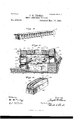
- Figure 1 is a sectional side view of a downdraft furnace made in accordance with my present invention, showing the same applied to an ordinary steam boiler.
- Fig. 2 is a front view thereof, one half of said figure beingin elevation, and the other half in section.
- Fig. 3 is a detail perspective View of one of the grate bars, one the blocks thereof being detached from the rest.
- Fig. 4 is a detail perspective View of one of the skew-backs which support the grate'bars.
- Fig. 5 is a lon- I gitudinal sectional view showing the method of constructing or forming the grate.
- Fig. 6 is a detail perspective view of the frame and spacing bars which support the grate bars while in process of construction.
- 10 represents an ordinary steam boiler beneath which my downdraft furnace may be applied.
- 11 is an upper or downdraft grate, which divides thefurnace into a fuel charging chamber 12, and a combustion chamber 13.
- skew-backs 17 which are preferably formed of fire-clay or other refractory material. These skew-backs extend across the furnace transversely, their inner faces having thereon projecting faces or bearing-blocks 18 (see Fig. 4), inclined on a radius of the curved grate bars.
- the faces 18 may be formed integral with the skewbacks and are at proper distances apart for the setting of the grate bars.
- the upper or downdraft grate 11 which is composed of a series of arched bars 19, these being preferably formed of fire-clay or other refractory material made in the form of blocks 20 as covered by my aforesaid patent.
- the blocks 20 in the present invention are set in place between the skewbacks above a suitable temporary support, a
- Fig. 5 is illustrated the method of placing the blocks of the grate bars in position
- Fig. 6 is illustrated the frame and spacing bars, which support the blocks while being placed in position.
- the arching of the grate bars permits their rising and falling intermediatethe skew-backs without their breaking or disturbing the supporting walls of the furnace, and without straining and injuring the grate bars themselves, as set forth in my aforesaid patent.
- the grate 22 is an ordinary updraft grate supported from the walls of the furnace at a suitable distance below the downdraft grate, the lower grate being fed with fuel by the unconsumed coal, which falls" from the upper grate.
- the grate 22 is arranged above the floor line.
- doors to the ash-pit 26 beneath the updraft grate 22 are provided with dampers 27 for the admission of air.
- the rear of the ash-pit is preferably slightly below the floor line, with its bottom sloping upwardly to the line of. the floor and the bottom of doors 25.
- Each of the doors 28 has an operating handle 30 attached to it, and a projection or pin 31 thereon, which is adapted to engage with notches 32 in an arm or lever 33 pivoted to the furnace front, allowing the doors 28 to be set and retained at any desired angle, so that more or less air can be admitted to the downdraft grate.
- a similar rib formed on the inside of the front, and serves as an additional support to the skew-back 17 at the front of the furnace, this skew-back resting on the rib 35 as shown in Figs. 1 and 5.
- This rib may fit in a recess formed in the back of such skew-back, so that, while strengthening the support of the skew-back, the front plate of the furnace will also be braced.
- 36 is a suitable wall or pier which is sprung from the bridge wall 16 preferably to the middle of the rear skew-back 17 and centrally braces such skew-back as well as the rear wall 15 of the furnace.
- a frame 37 of any suitable size and any desired number of spacing bars 38 are used, as shown in Figs. 5 and 6.
- Suitable temporary supporting blocks 39 may first be set on the lower grate 22 as shown in Fig. 5.
- the frame 37 is then set on top of such blocks, so that the ends of the frame are just under the projecting faces 18 of the skew-backs.
- the spacing bars 38 which have sloping sides (Fig. 6) of the same angle as the sloping sides of the blocks 20 (Figs.
- each block can only go down a certain uniform distance, which is such as to cause the blocks to form an arch having the same curve as the top of the spacing bars.
- the blocks forming the grate bars will, by reason of the baking of the clay between the blocks of the grate bars and between the grate bars and the skew-backs, be united firmly together and to the skew-backs, thus forming grate bars or an entire grate, which is practically in one piece.
- a furnace having a fuel-grate composed of arched .bars supported from skew-backs fixed in the transverse walls of the furnace, and a wall or pier sprung from the bridge wall and bracing the rear skew-back against lateral displacement.
- a furnace having a fuel-grate composed of arched bars supported from skew-backs fixed in the transverse walls of the furnace, a rib formed on the front of the furnace partly supporting the forward skew-back, and a wall or pier sprung from the bridge wall and bracing the rear skew-back against lateral displacement.
- a furnace having a fuel-grate composed of arched bars supported from skew-backs fixed in the transverse walls of the furnace,
Landscapes
- Engineering & Computer Science (AREA)
- Chemical & Material Sciences (AREA)
- Combustion & Propulsion (AREA)
- Mechanical Engineering (AREA)
- General Engineering & Computer Science (AREA)
- Incineration Of Waste (AREA)
Description
(No Model.) 3 Sheets-Sheet I.
J. M. THOMAS. SMOKE GONSUMING FURN'AGE.
No. 535,638. Patented Mar." 12, 1895.
- Wdwaooca avwewbo'c M 3391 attoznm p/ wxvi (No Model.) 3 Sheets-Sheet, 2.
J. M. THOMAS.
SMOKE GONSUMING'FURNAGE. No. 535,638. Patented Mar. 12, 1895.
qmw/ wi 20 witwaoaeo @J 9 a amvawboz c gm (No Model.) 3 SheetS -Sheet 3H J. M. THOMAS. SMOKE GONSUMING FURNACE.
'No. 535,638. Patented Mar. 12,1895;
wllmunmma l UNITED STATES PATENT OFFICE.
JOSEPH M... THOMAS, OF ST. LOUIS, MISSOURI.
SMOKE-CONSUMING FURNACE.
SPECIFICATION forming part of Letters Patent No. 535,638, dated March 12, 1895. Application filed June 4,1894- Serial No. 513,3'72- (No model.)
To all whom it may concern: Be it known that I, JOSEPH M. THOMAS, a citizen of the United .States, residing at St.
Louis, in the State of Missouri, have invented certain new and useful Improvements in Smoke-Consuming Furnaces, of which the following is such a full, clear, and exact description as will enable any one skilled in the art to which it appertains to make and use the same, reference being had to the accompanying drawings, forming part of this specification.
My invention relates to downdraft furnaces, more particularly for steam or other boilers, and to one of that class wherein the downdraft grate is formed of fire-brick or other refractory material, and is an improvement on the invention secured to me by Letters Patent No. 519,779, dated May 15, 1894:.
The invention will be best understood by the detailed description below.
In the drawings, Figure 1 is a sectional side view of a downdraft furnace made in accordance with my present invention, showing the same applied to an ordinary steam boiler. Fig. 2 is a front view thereof, one half of said figure beingin elevation, and the other half in section. Fig. 3 is a detail perspective View of one of the grate bars, one the blocks thereof being detached from the rest. Fig. 4 is a detail perspective View of one of the skew-backs which support the grate'bars. Fig. 5 is a lon- I gitudinal sectional view showing the method of constructing or forming the grate. Fig. 6 is a detail perspective view of the frame and spacing bars which support the grate bars while in process of construction.
In the drawings the same marks of reference indicate the same parts in the several figures.
10 represents an ordinary steam boiler beneath which my downdraft furnace may be applied.
11 is an upper or downdraft grate, which divides thefurnace into a fuel charging chamber 12, and a combustion chamber 13.
14: is the front wall or arch of the furnace, and 15 is a second arch or partition wall beneath the boiler shell in front of the bridge wall 16.
Set in the walls 14, and 15 below the fuel chamber doors, and above the rear outlets of the combustion chamber 13, are skew-backs 17 which are preferably formed of fire-clay or other refractory material. These skew-backs extend across the furnace transversely, their inner faces having thereon projecting faces or bearing-blocks 18 (see Fig. 4), inclined on a radius of the curved grate bars. The faces 18 may be formed integral with the skewbacks and are at proper distances apart for the setting of the grate bars. 7
Between the walls 14 and 15 and supported by the skew-backs is the upper or downdraft grate 11, which is composed of a series of arched bars 19, these being preferably formed of fire-clay or other refractory material made in the form of blocks 20 as covered by my aforesaid patent. The blocks 20 in the present invention are set in place between the skewbacks above a suitable temporary support, a
. binding agent 21 of suitable material in a green state, and preferably fiuxible, such as a mixture of green or unburnt clay, water and a flux in a plastic state, being interposed between the blocks, so that when the furnace is first put into use, the binding agent will be burned hard and the blocks thereby united firmly together, forming the grate bars in one piece.
In Fig. 5 is illustrated the method of placing the blocks of the grate bars in position, and in Fig. 6 is illustrated the frame and spacing bars, which support the blocks while being placed in position. The arching of the grate bars permits their rising and falling intermediatethe skew-backs without their breaking or disturbing the supporting walls of the furnace, and without straining and injuring the grate bars themselves, as set forth in my aforesaid patent.
22-is an ordinary updraft grate supported from the walls of the furnace at a suitable distance below the downdraft grate, the lower grate being fed with fuel by the unconsumed coal, which falls" from the upper grate. The grate 22 is arranged above the floor line.
23 are doors to the combustion chamber through which it is cleaned, each door having a suitable damper 24.
25 are doors to the ash-pit 26 beneath the updraft grate 22. They are provided with dampers 27 for the admission of air. The rear of the ash-pit is preferably slightly below the floor line, with its bottom sloping upwardly to the line of. the floor and the bottom of doors 25.
I have discovered by experiment that by employing a downdraft grate of refractory material, I am enabled to raise considerably the level of both the downdraft and updraft grates without disturbing the boiler setting and interfering with the functions of the furnace, thereby elevating the ash-pit, so that the door leading thereto is above the floor line, thus rendering the ash-pit easy to clean out.
28 are fuel-charging doors to the downdraft grate. They are pivoted at their to top the boiler front 29, and open inward, so that the incoming air will be directed on the coals of the downdraft grate, and cold air be thus prevented from striking the bottom of the boiler and cooling it.
Each of the doors 28 has an operating handle 30 attached to it, and a projection or pin 31 thereon, which is adapted to engage with notches 32 in an arm or lever 33 pivoted to the furnace front, allowing the doors 28 to be set and retained at any desired angle, so that more or less air can be admitted to the downdraft grate.
34: is a transverse strengthening rib formed just below the fuel-charging doors on the outside of the furnace front, to stiffen the furnace front and prevent it from bulging. 35
is a similar rib formed on the inside of the front, and serves as an additional support to the skew-back 17 at the front of the furnace, this skew-back resting on the rib 35 as shown in Figs. 1 and 5. This rib may fit in a recess formed in the back of such skew-back, so that, while strengthening the support of the skew-back, the front plate of the furnace will also be braced.
36 is a suitable wall or pier which is sprung from the bridge wall 16 preferably to the middle of the rear skew-back 17 and centrally braces such skew-back as well as the rear wall 15 of the furnace.
In setting the upper grate bars in position, a frame 37 of any suitable size and any desired number of spacing bars 38, are used, as shown in Figs. 5 and 6. Let us suppose the furnace to be complete with the exception of the downdraft grate. Suitable temporary supporting blocks 39 may first be set on the lower grate 22 as shown in Fig. 5. The frame 37 is then set on top of such blocks, so that the ends of the frame are just under the projecting faces 18 of the skew-backs. The spacing bars 38, which have sloping sides (Fig. 6) of the same angle as the sloping sides of the blocks 20 (Figs. 2 and 3) of which the grate bars are composed, and curved tops as shown, are then set in position in a line with the spaces between the projecting faces 18 of the skew-backs. The blocks 20 are set in place between the spacing bars 38, beginning from the skew-backs, and a binding agent of green or unburnt clay and water, in a plastic state, is put between each of the blocks and also between the blocks and the skew-backs. The spacing bars having sides sloping at the same angle as the grate bar blocks 20, when such blocks are set in place between the spacing bars, each block can only go down a certain uniform distance, which is such as to cause the blocks to form an arch having the same curve as the top of the spacing bars.
After a number of arches have been completed in the manner described, by removing the supporting blocks 39 from below the frame 38, such frame will drop down, as will also the spacing bars from between the grate bars, when another series of grate bars may be putin place, in the same manner alongside of the first series, and so on until the entire grate is completed.
After the furnace is completed, a fire is started on the downdraft grate. The blocks forming the grate bars will, by reason of the baking of the clay between the blocks of the grate bars and between the grate bars and the skew-backs, be united firmly together and to the skew-backs, thus forming grate bars or an entire grate, which is practically in one piece.
The difficulty with grate bars made in one piece in the first instance, is that in burning them in a kiln they will warp and buckle, and thus not be adapted to fit the space designed for them. So too, such one-piece grate bars are likely to be broken in handling and are besides cumbersome to handle. So als'o, sizes of infinite variety would have to be made and kept on hand, were the bars made in one piece in process of manufacture. With my method of construction, these difficulties are obviated.
Having fully described my invention,.what I claim as new, and desire to secure by Letters Patent of the United States, is
1. A furnace havinga fuel-grate composed of arched bars supported from skew-backs fixed in the transverse walls of the furnace, a rib formed on the inside of the front of the furnace partly supporting the forward skewbacks, and a rib on the outside of the furnace front,=bracing such forward skew-back.
2. A furnace having a fuel-grate composed of arched .bars supported from skew-backs fixed in the transverse walls of the furnace, and a wall or pier sprung from the bridge wall and bracing the rear skew-back against lateral displacement.
3. A furnace havinga fuel-grate composed of arched bars supported from skew-backs fixed in the transverse walls of the furnace, a rib formed on the front of the furnace partly supporting the forward skew-back, and a wall or pier sprung from the bridge wall and bracing the rear skew-back against lateral displacement.
4. A furnace having a fuel-grate composed of arched bars supported from skew-backs fixed in the transverse walls of the furnace,
projecting faces on such skew-backs from In testimony whereof I have hereunto set which such arches are sprung, a rib formed my hand and afiixed my seal, this 29th day of 10 on the front of the furnace partly supporting May, 1894:, in the'presence of the two subscribthe forward skew-back, a rib on the outside ing witnesses.
5 of the furnace frontbracingtheforward skew- JOSEPH M. THOMAS. [L. s]
back, and a pier sprung from the bridge-wall Witnesses: bracing the rear skew-back against lateral A. O. FOWLER,
displacement. STANLEY STORER.
Publications (1)
| Publication Number | Publication Date |
|---|---|
| US535638A true US535638A (en) | 1895-03-12 |
Family
ID=2604399
Family Applications (1)
| Application Number | Title | Priority Date | Filing Date |
|---|---|---|---|
| US535638D Expired - Lifetime US535638A (en) | Smoke-consuming furnace |
Country Status (1)
| Country | Link |
|---|---|
| US (1) | US535638A (en) |
-
0
- US US535638D patent/US535638A/en not_active Expired - Lifetime
Similar Documents
| Publication | Publication Date | Title |
|---|---|---|
| US566924A (en) | Furnace for steam-generators | |
| US535638A (en) | Smoke-consuming furnace | |
| US519779A (en) | Smoke-consuming furnace | |
| US390191A (en) | Carl sah leb | |
| US360182A (en) | Furnace | |
| US545463A (en) | eyerhard | |
| US82313A (en) | heatley | |
| US724993A (en) | Duplex furnace. | |
| US423926A (en) | hatch | |
| US2416A (en) | Liaed | |
| US1211782A (en) | Steam-boiler furnace. | |
| US579910A (en) | Smokeless furnace | |
| US104291A (en) | Improvement in limekilns | |
| US501380A (en) | swift | |
| US56919A (en) | Improved pljae-weldlng rof | |
| US136413A (en) | Improvement in furnaces for reheating metals | |
| US543739A (en) | Steam-boiler furnace | |
| US579233A (en) | Boiler-furnace | |
| US140343A (en) | Improvement in brick-kilns | |
| US630091A (en) | Smoke-consuming steam-boiler furnace. | |
| US641873A (en) | Furnace. | |
| US268035A (en) | mcauley | |
| US750860A (en) | Smoke-consumer | |
| US983510A (en) | Smoke-consuming furnace. | |
| US1097735A (en) | Smokeless boiler-furnace. |