US5328061A - Sliding dispensing cap and dispensing stopper - Google Patents
Sliding dispensing cap and dispensing stopper Download PDFInfo
- Publication number
- US5328061A US5328061A US07/978,406 US97840692A US5328061A US 5328061 A US5328061 A US 5328061A US 97840692 A US97840692 A US 97840692A US 5328061 A US5328061 A US 5328061A
- Authority
- US
- United States
- Prior art keywords
- bottle
- opening
- stopper
- dispensing
- way valve
- Prior art date
- Legal status (The legal status is an assumption and is not a legal conclusion. Google has not performed a legal analysis and makes no representation as to the accuracy of the status listed.)
- Expired - Lifetime
Links
Images

Classifications
-
- B—PERFORMING OPERATIONS; TRANSPORTING
- B65—CONVEYING; PACKING; STORING; HANDLING THIN OR FILAMENTARY MATERIAL
- B65D—CONTAINERS FOR STORAGE OR TRANSPORT OF ARTICLES OR MATERIALS, e.g. BAGS, BARRELS, BOTTLES, BOXES, CANS, CARTONS, CRATES, DRUMS, JARS, TANKS, HOPPERS, FORWARDING CONTAINERS; ACCESSORIES, CLOSURES, OR FITTINGS THEREFOR; PACKAGING ELEMENTS; PACKAGES
- B65D47/00—Closures with filling and discharging, or with discharging, devices
- B65D47/04—Closures with discharging devices other than pumps
- B65D47/20—Closures with discharging devices other than pumps comprising hand-operated members for controlling discharge
- B65D47/26—Closures with discharging devices other than pumps comprising hand-operated members for controlling discharge with slide valves, i.e. valves that open and close a passageway by sliding over a port, e.g. formed with slidable spouts
- B65D47/28—Closures with discharging devices other than pumps comprising hand-operated members for controlling discharge with slide valves, i.e. valves that open and close a passageway by sliding over a port, e.g. formed with slidable spouts having linear movement
- B65D47/286—Closures with discharging devices other than pumps comprising hand-operated members for controlling discharge with slide valves, i.e. valves that open and close a passageway by sliding over a port, e.g. formed with slidable spouts having linear movement between planar parts
Definitions
- This invention relates in general to dispenser bottles and in particular to a novel squeeze bottle which has a sliding dispenser cap and a dispenser stopper.
- the present invention comprises a novel squeeze bottle which has a dispensing tube which is integrally formed with the bottle and which extends on the outside thereof and is attached to the outer surface of the bottle and which has a receiving end that extends into the container.
- a dispensing tube which is integrally formed with the bottle and which extends on the outside thereof and is attached to the outer surface of the bottle and which has a receiving end that extends into the container.
- the product is forced up through the dispensing tube and through a radial opening formed in the stopper and out an orifice into the sliding dispensing nozzle.
- the slide nozzle is moved so as to close the dispensing orifice and air can pass under the slide nozzle into a central orifice through a one-way valve formed in the stopper into the container to fill it with air.
- the one-way valve prevents air from exiting from the container so that the product is forced up through the discharge tube.
- Various products can be dispensed such as cosmetics, liquid soaps, lotions, shampoos, and foods such as oil, ketchup, mustard. Also cleaners such as detergents and wax can be dispensed with the novel dispensing container of the invention.
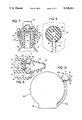
- FIG. 1 is a side plan view of the dispensing bottle of the invention
- FIG. 2 is a top plan view of the dispensing bottle
- FIG. 3 is a sectional view of the stopper and slide dispensing mechanism of the invention.
- FIG. 4 is a top plan view of the slide dispenser of the invention taken on line IV--IV of FIG. 3;
- FIG. 5 is a sectional view taken on line V--V of FIG. 3;
- FIG. 6 is a sectional view with the slide nozzle in the off position
- FIG. 7 is a sectional view transverse to FIG. 3;
- FIG, 8 is a sectional view taken on VIII--VIII of FIG, 3;
- FIG. 9 is a sectional view illustrating the one-way valve in the open position.
- FIG. 10 is a side plan view of a modified form of the invention.
- FIGS. 1 and 2 illustrate flexible bottle 10 with a dispenser stopper and nozzle.
- a bottle 11 has an integrally formed dispensing tube 12 attached to one side thereof which has a fluid connection 15 with the bottom of the bottle 11.
- the tube 12 has a portion 13 which extends up to the stopper and dispensing nozzle.
- the bottle 11 has a reduced orifice 16 which is connected to a larger cylindrical portion 14 as shown in FIGS. 3, 6 and 7.
- a stopper 41 has a first portion 40 which is receivable in the reduced portion 16 of the bottle and has an enlarged portion 43 that is received in the portion 14 of the bottle.
- a flange 44 is formed on one end of the stopper 41 and engages the upper end of the enlarged portion 14.
- a central opening 47 extends through the stopper 41 from inside the bottle to a smaller orifice 48 which communicates with a valve chamber 50 in which a one-way valve 52 is mounted.
- the flap valve 52 is formed with a pair of flexible legs 53 and 54 which bias it to the right relative to FIG. 3 in the valve chamber 50.
- a dispenser lid 17 is formed with internal threads 33 which mate with external threads 32 on the bottle portion 14 so that the lid 17 can be attached to the bottle.
- the lid 17 has a central passage 51 which aligns with the valve chamber 50.
- the lid 17 also has an opening 91 which aligns with a passageway 61 that is fluidly connected with the end of dispenser tube 13 as shown in FIG. 3.
- a slide dispenser 18 is mounted on the cap 17 and is moveable in grooves 24 and 26 which engage edges 27 and 28 of the dispenser 18 as shown, for example, in FIG. 4.
- the stopper 41 is formed with an opening 61 that communicates with the end 13 of tube 12.
- a first pair of webs 84 and 86 extend radially inwardly on either side of passage 61 to the center portion 46 of the stopper.
- Other webs 80, 81, 82 and 83 also extend between the outer portion of the stopper and the central portion 46 as shown.
- the slide nozzle 18 has a thumb portion 20 and an air passage 90 is formed between the slide nozzle 18 and the opening 51 through the cover 17 so that air can pass as shown by the arrow in FIG. 9 and the air passes through the opening 51 by one-way valve 52 into the opening 48 and opening 47 of the stopper and into the bottle 11 to fill it with air after product has been dispensed.
- FIG. 8 is a sectional view on line VIII--VIII in FIG. 3 and illustrates the communication of the tube 12 and its end 13 with the opening 61.
- the downwardly extending sidewalls 29 of the cover 17 are provided with threads 33 which mate with the threads 32 so that the opening 62 aligns with the opening 61 as shown in FIG. 9, for example.
- the slide nozzle 18 is moved to the position shown in FIG. 3 and the bottle 11 is compressed by the user so as to force product through the opening 15 and tube 12 then through tube portion 13 into the opening 61 and through the opening 62 in the cap 17 and through opening 91 in the slide dispenser 18 and out nozzle 19 when it has been moved to the dispensing position as shown in FIG. 3.
- the product enters the discharge nozzle 19 and is ejected from the end opening 21.
- the compression force on the bottle 11 will be removed by the operator such that air can pass through opening 90 and through opening 51 pass the one-way valve 52 into the opening 47 and enter the bottle 11.
- the one-way valve 52 is closed when the bottle 11 is compressed by the user to eject product because the inside pressure in the bottle moves the valve 52 to the right relative to FIG. 9 so that it seats on the valve seat 70 of the lid 17 which is formed about the opening 51 above the valve chamber 50.
- the nozzle slide 18 may be returned to the position shown in FIG. 6 so that the opening 91 does not align with the opening 62 in the cover 17. At this time, air can pass through the openings 90 under the slide 18 and through opening 51 and one-way valve 52 into the bottle.
- FIG. 10 illustrates a modified form of the bottle wherein a disc-shaped bottle 100 is formed with a base 101.
- the bottle has a dispensing tube 102.
- the reduced portion of the neck 16a and the enlarged portion 14a are the same as in the embodiment illustrated in FIG. 1 and the lid 17 and slide nozzle 18 and the internal stopper construction are the same as in the first embodiment.
Landscapes
- Engineering & Computer Science (AREA)
- Mechanical Engineering (AREA)
- Closures For Containers (AREA)
Abstract
Description
Claims (2)
Priority Applications (1)
| Application Number | Priority Date | Filing Date | Title |
|---|---|---|---|
| US07/978,406 US5328061A (en) | 1992-11-18 | 1992-11-18 | Sliding dispensing cap and dispensing stopper |
Applications Claiming Priority (1)
| Application Number | Priority Date | Filing Date | Title |
|---|---|---|---|
| US07/978,406 US5328061A (en) | 1992-11-18 | 1992-11-18 | Sliding dispensing cap and dispensing stopper |
Publications (1)
| Publication Number | Publication Date |
|---|---|
| US5328061A true US5328061A (en) | 1994-07-12 |
Family
ID=25526062
Family Applications (1)
| Application Number | Title | Priority Date | Filing Date |
|---|---|---|---|
| US07/978,406 Expired - Lifetime US5328061A (en) | 1992-11-18 | 1992-11-18 | Sliding dispensing cap and dispensing stopper |
Country Status (1)
| Country | Link |
|---|---|
| US (1) | US5328061A (en) |
Cited By (8)
| Publication number | Priority date | Publication date | Assignee | Title |
|---|---|---|---|---|
| WO1996022152A1 (en) | 1995-01-17 | 1996-07-25 | Utterberg David S | Flow-through treatment device |
| EP0875460A1 (en) * | 1997-05-02 | 1998-11-04 | Soplar Sa | Multi-compartment plastic bottle made by blowing |
| US5927565A (en) * | 1997-05-16 | 1999-07-27 | Paczonay; Joseph R. | Vented valve assembly for liquid containers |
| US6135358A (en) * | 1997-10-17 | 2000-10-24 | Mefar S.P.A. | Apparatus for washing the nasal cavities |
| US6398133B1 (en) | 1999-12-22 | 2002-06-04 | Emsar, Inc. | Dispensing head for a squeeze dispenser |
| US20050029276A1 (en) * | 2003-08-06 | 2005-02-10 | Johnson David B. | Condiment container |
| KR100610420B1 (en) * | 1999-04-14 | 2006-08-09 | 메파르 에스.피.에이. | Nasal Wash Device |
| ES2613281A1 (en) * | 2015-11-20 | 2017-05-23 | Emprion, S.L. | An accessory dispenser of carbonated drinks contained in a bottle and a container provided with said accessory (Machine-translation by Google Translate, not legally binding) |
Citations (11)
| Publication number | Priority date | Publication date | Assignee | Title |
|---|---|---|---|---|
| US4408703A (en) * | 1981-05-13 | 1983-10-11 | Libit Sidney M | Dispenser coffee cap |
| US4429815A (en) * | 1981-11-12 | 1984-02-07 | Libit Sidney M | Rotating dispenser cap |
| US4600130A (en) * | 1983-09-29 | 1986-07-15 | Libit Sidney M | Squeeze pressure dispenser with integral siphon tube |
| JPS649168A (en) * | 1987-03-02 | 1989-01-12 | Crown Cork Japan | Container lid equipped with automatic opening and closing mechanism |
| US5033654A (en) * | 1990-02-23 | 1991-07-23 | R.J.S. Industries, Inc. | Foam dispenser |
| US5048750A (en) * | 1988-04-05 | 1991-09-17 | Supermatic Kunststoff Ag | Device for producing and dispensing foam |
| US5054634A (en) * | 1988-03-01 | 1991-10-08 | Societe De Conseils Et D'etudes De Emballages - S.C.E.E. | Capsule with a drawer and a sliding cursor |
| US5110051A (en) * | 1991-03-01 | 1992-05-05 | Bennett Robert A | Squeeze sprayer device |
| US5114051A (en) * | 1989-02-09 | 1992-05-19 | Patrick Simon | Closing capsule with a mobile element for flasks and other containers |
| US5115949A (en) * | 1989-04-06 | 1992-05-26 | Bielsteiner Verschlusstechnik Gmbh | Flexible liquid container with a sliding closure cap |
| US5115946A (en) * | 1991-02-11 | 1992-05-26 | Libit Sidney M | Squeeze bottle |
-
1992
- 1992-11-18 US US07/978,406 patent/US5328061A/en not_active Expired - Lifetime
Patent Citations (11)
| Publication number | Priority date | Publication date | Assignee | Title |
|---|---|---|---|---|
| US4408703A (en) * | 1981-05-13 | 1983-10-11 | Libit Sidney M | Dispenser coffee cap |
| US4429815A (en) * | 1981-11-12 | 1984-02-07 | Libit Sidney M | Rotating dispenser cap |
| US4600130A (en) * | 1983-09-29 | 1986-07-15 | Libit Sidney M | Squeeze pressure dispenser with integral siphon tube |
| JPS649168A (en) * | 1987-03-02 | 1989-01-12 | Crown Cork Japan | Container lid equipped with automatic opening and closing mechanism |
| US5054634A (en) * | 1988-03-01 | 1991-10-08 | Societe De Conseils Et D'etudes De Emballages - S.C.E.E. | Capsule with a drawer and a sliding cursor |
| US5048750A (en) * | 1988-04-05 | 1991-09-17 | Supermatic Kunststoff Ag | Device for producing and dispensing foam |
| US5114051A (en) * | 1989-02-09 | 1992-05-19 | Patrick Simon | Closing capsule with a mobile element for flasks and other containers |
| US5115949A (en) * | 1989-04-06 | 1992-05-26 | Bielsteiner Verschlusstechnik Gmbh | Flexible liquid container with a sliding closure cap |
| US5033654A (en) * | 1990-02-23 | 1991-07-23 | R.J.S. Industries, Inc. | Foam dispenser |
| US5115946A (en) * | 1991-02-11 | 1992-05-26 | Libit Sidney M | Squeeze bottle |
| US5110051A (en) * | 1991-03-01 | 1992-05-05 | Bennett Robert A | Squeeze sprayer device |
Cited By (8)
| Publication number | Priority date | Publication date | Assignee | Title |
|---|---|---|---|---|
| WO1996022152A1 (en) | 1995-01-17 | 1996-07-25 | Utterberg David S | Flow-through treatment device |
| EP0875460A1 (en) * | 1997-05-02 | 1998-11-04 | Soplar Sa | Multi-compartment plastic bottle made by blowing |
| US5927565A (en) * | 1997-05-16 | 1999-07-27 | Paczonay; Joseph R. | Vented valve assembly for liquid containers |
| US6135358A (en) * | 1997-10-17 | 2000-10-24 | Mefar S.P.A. | Apparatus for washing the nasal cavities |
| KR100610420B1 (en) * | 1999-04-14 | 2006-08-09 | 메파르 에스.피.에이. | Nasal Wash Device |
| US6398133B1 (en) | 1999-12-22 | 2002-06-04 | Emsar, Inc. | Dispensing head for a squeeze dispenser |
| US20050029276A1 (en) * | 2003-08-06 | 2005-02-10 | Johnson David B. | Condiment container |
| ES2613281A1 (en) * | 2015-11-20 | 2017-05-23 | Emprion, S.L. | An accessory dispenser of carbonated drinks contained in a bottle and a container provided with said accessory (Machine-translation by Google Translate, not legally binding) |
Similar Documents
| Publication | Publication Date | Title |
|---|---|---|
| EP0254138B1 (en) | Container closure cap with metering appliance | |
| US3874562A (en) | Dispensing closure with pump parts and container using the same | |
| US6446844B1 (en) | Closure with internal flow control for a pressure openable valve in an extendable/retractable nozzle | |
| CA1296302C (en) | Push up dispenser with capsule valve | |
| US6749092B2 (en) | Deformable dispensing valve | |
| US4408702A (en) | Automatic dispenser cap | |
| US5938082A (en) | Container assembly having snap-fit container connection | |
| US4798311A (en) | Container provided with a closure | |
| US5873494A (en) | Dual stream liquid dispensing structure | |
| CN101980926B (en) | Closure having a drip minimizing lid | |
| US5593065A (en) | Metered dual dispenser cap for squeeze containers | |
| US3545682A (en) | Dispensing device | |
| US20020096540A1 (en) | Inverted package dispensing system | |
| JPH11349023A (en) | Proper quantity takeout head | |
| US4519530A (en) | Self-closing dispenser | |
| US6227417B1 (en) | Pressurized device | |
| CN107735340A (en) | Compressible valve and actuator for pressurizing vessel | |
| CN107810355A (en) | Compressible valve for pressurizing vessel | |
| US3963150A (en) | Puff-discharge squeeze bottle | |
| US5328061A (en) | Sliding dispensing cap and dispensing stopper | |
| US3451597A (en) | Container-dispenser with integral pump | |
| US4480768A (en) | Hand-operated pump | |
| US5390828A (en) | Closure with two-part slidable dispensing cap | |
| CA1324113C (en) | Multiple flow dispensing cap | |
| CN113348038B (en) | Dosage-measuring dispenser and method of use |
Legal Events
| Date | Code | Title | Description |
|---|---|---|---|
| AS | Assignment |
Owner name: LIBIT, JEFFREY M., NEW MEXICO Free format text: ASSIGNMENT OF ASSIGNORS INTEREST.;ASSIGNOR:LIBIT, SIDNEY M.;REEL/FRAME:006313/0764 Effective date: 19921113 |
|
| STCF | Information on status: patent grant |
Free format text: PATENTED CASE |
|
| FEPP | Fee payment procedure |
Free format text: PAYOR NUMBER ASSIGNED (ORIGINAL EVENT CODE: ASPN); ENTITY STATUS OF PATENT OWNER: SMALL ENTITY |
|
| FPAY | Fee payment |
Year of fee payment: 4 |
|
| REMI | Maintenance fee reminder mailed | ||
| FPAY | Fee payment |
Year of fee payment: 8 |
|
| SULP | Surcharge for late payment |
Year of fee payment: 7 |
|
| FPAY | Fee payment |
Year of fee payment: 12 |
|
| SULP | Surcharge for late payment |
Year of fee payment: 11 |