US5312361A - Automatic cannulation device - Google Patents
Automatic cannulation device Download PDFInfo
- Publication number
- US5312361A US5312361A US07/929,182 US92918292A US5312361A US 5312361 A US5312361 A US 5312361A US 92918292 A US92918292 A US 92918292A US 5312361 A US5312361 A US 5312361A
- Authority
- US
- United States
- Prior art keywords
- catheter
- chamber
- piston
- needle
- blood
- Prior art date
- Legal status (The legal status is an assumption and is not a legal conclusion. Google has not performed a legal analysis and makes no representation as to the accuracy of the status listed.)
- Expired - Lifetime
Links
Images


Classifications
-
- A—HUMAN NECESSITIES
- A61—MEDICAL OR VETERINARY SCIENCE; HYGIENE
- A61M—DEVICES FOR INTRODUCING MEDIA INTO, OR ONTO, THE BODY; DEVICES FOR TRANSDUCING BODY MEDIA OR FOR TAKING MEDIA FROM THE BODY; DEVICES FOR PRODUCING OR ENDING SLEEP OR STUPOR
- A61M25/00—Catheters; Hollow probes
- A61M25/01—Introducing, guiding, advancing, emplacing or holding catheters
- A61M25/06—Body-piercing guide needles or the like
- A61M25/0612—Devices for protecting the needle; Devices to help insertion of the needle, e.g. wings or holders
-
- A—HUMAN NECESSITIES
- A61—MEDICAL OR VETERINARY SCIENCE; HYGIENE
- A61M—DEVICES FOR INTRODUCING MEDIA INTO, OR ONTO, THE BODY; DEVICES FOR TRANSDUCING BODY MEDIA OR FOR TAKING MEDIA FROM THE BODY; DEVICES FOR PRODUCING OR ENDING SLEEP OR STUPOR
- A61M5/00—Devices for bringing media into the body in a subcutaneous, intra-vascular or intramuscular way; Accessories therefor, e.g. filling or cleaning devices, arm-rests
- A61M5/14—Infusion devices, e.g. infusing by gravity; Blood infusion; Accessories therefor
- A61M5/158—Needles for infusions; Accessories therefor, e.g. for inserting infusion needles, or for holding them on the body
- A61M2005/1585—Needle inserters
-
- A—HUMAN NECESSITIES
- A61—MEDICAL OR VETERINARY SCIENCE; HYGIENE
- A61M—DEVICES FOR INTRODUCING MEDIA INTO, OR ONTO, THE BODY; DEVICES FOR TRANSDUCING BODY MEDIA OR FOR TAKING MEDIA FROM THE BODY; DEVICES FOR PRODUCING OR ENDING SLEEP OR STUPOR
- A61M5/00—Devices for bringing media into the body in a subcutaneous, intra-vascular or intramuscular way; Accessories therefor, e.g. filling or cleaning devices, arm-rests
- A61M5/14—Infusion devices, e.g. infusing by gravity; Blood infusion; Accessories therefor
- A61M5/158—Needles for infusions; Accessories therefor, e.g. for inserting infusion needles, or for holding them on the body
- A61M2005/1587—Needles for infusions; Accessories therefor, e.g. for inserting infusion needles, or for holding them on the body suitable for being connected to an infusion line after insertion into a patient
-
- A—HUMAN NECESSITIES
- A61—MEDICAL OR VETERINARY SCIENCE; HYGIENE
- A61M—DEVICES FOR INTRODUCING MEDIA INTO, OR ONTO, THE BODY; DEVICES FOR TRANSDUCING BODY MEDIA OR FOR TAKING MEDIA FROM THE BODY; DEVICES FOR PRODUCING OR ENDING SLEEP OR STUPOR
- A61M5/00—Devices for bringing media into the body in a subcutaneous, intra-vascular or intramuscular way; Accessories therefor, e.g. filling or cleaning devices, arm-rests
- A61M5/14—Infusion devices, e.g. infusing by gravity; Blood infusion; Accessories therefor
- A61M5/158—Needles for infusions; Accessories therefor, e.g. for inserting infusion needles, or for holding them on the body
- A61M2005/1588—Needles for infusions; Accessories therefor, e.g. for inserting infusion needles, or for holding them on the body having means for monitoring, controlling or visual inspection, e.g. for patency check, avoiding extravasation
-
- A—HUMAN NECESSITIES
- A61—MEDICAL OR VETERINARY SCIENCE; HYGIENE
- A61M—DEVICES FOR INTRODUCING MEDIA INTO, OR ONTO, THE BODY; DEVICES FOR TRANSDUCING BODY MEDIA OR FOR TAKING MEDIA FROM THE BODY; DEVICES FOR PRODUCING OR ENDING SLEEP OR STUPOR
- A61M5/00—Devices for bringing media into the body in a subcutaneous, intra-vascular or intramuscular way; Accessories therefor, e.g. filling or cleaning devices, arm-rests
- A61M5/178—Syringes
- A61M5/31—Details
- A61M2005/3112—Incorporating self-aspirating means, e.g. to provide flashback
-
- A—HUMAN NECESSITIES
- A61—MEDICAL OR VETERINARY SCIENCE; HYGIENE
- A61M—DEVICES FOR INTRODUCING MEDIA INTO, OR ONTO, THE BODY; DEVICES FOR TRANSDUCING BODY MEDIA OR FOR TAKING MEDIA FROM THE BODY; DEVICES FOR PRODUCING OR ENDING SLEEP OR STUPOR
- A61M25/00—Catheters; Hollow probes
- A61M25/01—Introducing, guiding, advancing, emplacing or holding catheters
- A61M25/06—Body-piercing guide needles or the like
- A61M25/0693—Flashback chambers
Definitions
- This invention relates to blood vessel cannulation devices and is particularly directed to automatic means for catheter placement within blood vessels.
- Cannulating blood vessels is a common procedure in patient care, in order to administer fluids, drugs, blood or blood products.
- catheter for accomplishing cannulation.
- the needle is within the catheter; while in the other instance, the catheter is within the needle.
- the needle serves to penetrate the skin and the wall of the blood vessel and, once the blood vessel has been entered, the catheter is advanced manually until an adequate position is reached.
- such manual catheter placement involves both of the operator's hands; one for stabilization of the needle, and the other for advancement of the catheter.
- an improved catheter placement device comprising a needle, a catheter concentric with the needle, resilient means urging said catheter to an advanced position, and means for triggering the resilient means upon penetration of the wall of a blood vessel.
- the triggering means may be manual or may include means for sensing penetration of a blood vessel and for automatically advancing the catheter in response to such penetration.
- Another object of the present invention is to provide an improved catheter placement device which permits onehanded insertion and placement of a catheter.
- An additional object of the present invention is to provide an improved catheter placement device which permits automatic advancement of the catheter, once a blood vessel has been penetrated.
- a specific object of the present invention is to provide an improved catheter placement device comprising a needle, a catheter concentric with the needle, self-propelled, automatic means for catheter advancement, and means for triggering said means for self-propelled advancement upon penetration of the wall of a blood vessel.
- the triggering means may be manual or may include means for sensing penetration of a blood vessel and for automatically advancing the catheter in response to such penetration.
- FIG. 1 is a transverse section through a catheter placement device embodying the present invention
- FIG. 2 is a view, similar to that of FIG. 1, showing the catheter placement device is its unlocked position;
- FIG. 3 is a vertical section through the catheter placement device of FIG. 1, taken on the line 44 of FIG. 1;
- FIG. 4 is a plan view of the latch member of the catheter placement device of FIG. 1;
- FIG. 5 is a transverse section through an alternative form of the catheter placement device of FIG. 1, shown in the unarmed condition;
- FIG. 6 is a view showing the catheter placement device of FIG. 5 in its armed condition, after penetration of the skin, but prior to penetration of a blood vessel;
- FIG. 7 is a view showing the catheter placement device of FIG. 5 immediately following penetration of a blood vessel
- FIG. 8 is a view showing the catheter placement device of FIG. 5 following advancement of the catheter;
- FIG. 9 is transverse section through another alternative form of the catheter placement device of FIG. 1, shown in its unarmed condition;
- FIG. 10 is a view showing the catheter placement device of FIG. 9 in its armed condition, after penetration of the skin, but prior to penetration of a blood vessel;
- FIG. 11 is a view showing the catheter placement device of FIG. 9 immediately after penetration of a blood vessel;
- FIG. 12 is a view showing the catheter placement device of FIG. 9 following advancement of the catheter;
- FIG. 13 is a transverse section through a further alternative form of the catheter placement device of FIG. 1, shown in its unarmed condition;
- FIG. 14 is a view showing the catheter placement device of FIG. 13 in its armed condition, after penetration of the skin, but prior to penetration of a blood vessel;
- FIG. 15 is a view showing the catheter placement device of FIG. 13 in its armed condition, after penetration of the skin, but prior to penetration of a blood vessel;
- FIG. 16 is a view showing the catheter placement device of FIG. 13 following advancement of the catheter;
- FIG. 17 is a view, similar to that of FIG. 1, showing another alternative form of the catheter placement device of FIG. 1;
- FIG. 18 is a view, similar to FIG. 5, showing another alternative form of the catheter placement device of FIG. 5;
- FIG. 19 is a view, similar to that of FIG. 5, showing an additional alternative form of the catheter placement device of FIG. 5;
- FIG. 20 is a view, similar to FIG. 9, showing a further alternative form of the catheter placement device of FIG. 9;
- FIG. 21 is a view, similar to that of FIG. 20, showing the catheter placement device of FIG. 20 in its "armed" position;
- FIG. 22 is a view, similar to that of FIG. 9, showing another alternative form of the catheter placement device of FIG. 9;
- FIG. 23 is a view, similar to that of FIG. 22 showing the catheter placement device of FIG. 21 in its "armed" position;
- FIG. 24 is a view, similar to that of FIG. 22 showing the catheter placement device of FIG. 22 immediately after penetration of a blood vessel;
- FIG. 25 is a view, similar to that of FIG. 22 showing the catheter placement device of FIG. 22 immediately after release of the catheter;
- FIG. 26 is a view, similar to that of FIG. 9, showing an additional alternative form of the catheter placement device of FIG. 9;
- FIG. 27 shows an alternative form of the catheter placement device with an automatic arming rod
- FIG. 28 shows a cross-section of the automatic arming rod of FIG. 27
- FIG. 29 is a view, similar to that of FIG. 27, showing the catheter placement device of FIG. 27 after skin penetration and the beginning of the automatic arming process;
- FIG. 30 is a view, similar to that of FIG. 27, showing the catheter placement device of FIG. 27 after skin penetration, in a further stage of the arming process;
- FIG. 31 is a view, similar to that of FIG. 27, showing the catheter placement device of FIG. 27 immediately after penetration of a blood vessel;
- FIG. 32 is a view, similar to that of FIG. 27, showing the catheter placement device of FIG. 27 immediately after release of the catheter;
- FIG. 33 is a view, similar to that of FIG. 27, after the removal of the needle, showing connection of the catheter with the intravenous tubing;
- FIG. 34 shows an additional alternative form of the catheter placement device
- FIG. 35 is a view, similar to that of FIG. 34, showing the catheter placement device of FIG. 34 immediately after skin penetration;
- FIG. 36 is a view, similar to that of FIG. 34, showing the catheter placement device of FIG. 34, immediately after release of the catheter;
- FIG. 37 is a view, similar to that of FIG. 9, showing an additional form of the catheter placement device of FIG. 9;
- FIG. 38 is a view, similar to that of FIG. 5, showing an alternative form of the catheter placement device of FIG. 5 prior to skin penetration;
- FIG. 39 is a view, similar to that of FIG. 38, showing the catheter placement device of FIG. 38 immediately after skin penetration;
- FIG. 40 is a view, similar to that of FIG. 38, showing the catheter placement device of FIG. 38 immediately after blood vessel penetration;
- FIG. 41 is a view, similar to that of FIG. 38, showing the catheter of the catheter placement device of FIG. 38 placed intravenously;
- FIG. 42 shows the separate four components of a further alternative form of the catheter placement device
- FIG. 43 shows the device of FIG. 42 while being assembled
- FIG. 44 shows a further stage on the assembly of catheter placement device of FIG. 42;
- FIG. 45 shows the assembled unit of FIG. 42 prior to skin penetration
- FIG. 46 shows the assembled unit of FIG. 42 after penetration into a blood vessel
- FIG. 47 shows the disengaging of the propelling unit of FIG. 42 from the catheter placed intravenously
- FIG. 48 shows an alternative form of the catheter placement device of FIG. 5;
- FIG. 49 shows a top view of the same catheter device of FIG. 48;
- FIG. 50 shows the catheter placement device of FIG. 48 after blood vessel penetration
- FIG. 51 shows an alternative form of a semi-automatic catheter placement device
- FIG. 52 shows the catheter placement device of FIG. 51 after blood vessel penetration.
- FIG. 53 shows yet an alternative form of a fully automatic catheter placement device, where the means for sensing penetration are represented by an opto-electric source-sensor pair.
- FIG. 54 show an alternative form of the device of FIG. 53 where the represented sensors are temperature sensors.
- FIG. 55 show an alternative form of the device of FIG. 53 where the represented sensors are sensors detecting the electrical conductivity properties of the blood.
- FIG. 56 shows an alternative form of the device of FIG. 53 in which the represented sensor is a flow detector sensor.
- FIG. 57 shows an alternative device of FIG. 53, where the represented sensor is an acoustic sensor.
- FIG. 58 shows yet an alternative form of the device of FIG. 53 in which the represented sensor is a pressure sensor.
- FIG. 59 shows yet an alternative form of the device of FIG. 53 in which the represented sensor is an illustration of a sensor of chemical properties of the blood, such as a pH sensor, or of a sensor capable of sensing presence of blood by detecting presence of a component of the blood, such as oxygen.
- the represented sensor is an illustration of a sensor of chemical properties of the blood, such as a pH sensor, or of a sensor capable of sensing presence of blood by detecting presence of a component of the blood, such as oxygen.
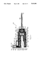
- a catheter placement device comprising a needle 12, having a tubular hollow shaft 14 projecting from a handle portion or needle hub 16, and a flexible catheter 18 projecting from a hub 20.
- the catheter 18 concentrically encircles the shaft 14 of the needle 12, while the catheter hub 20 telescopes over the forward portion of the needle handle portion 16.
- the needle 12 may be made to concentrically telescope over the catheter 18.
- the catheter hub 20 has a radial flange 22 formed adjacent the rear end 24 of the hub 20 and has a lever 26, formed of resilient material, projecting rearwardly from one side of the flange 22 and having an opening 28 formed adjacent the free end of the lever 26, as best seen in FIG. 4.
- a bridge member 30 projects radially outward from the needle handle 16 and, as best seen in FIG. 3, has an aperture 32 formed therein to receive the lever 26 and has a stud 34 projecting into the aperture 32 which is mateable with the opening 28 of the lever 26 to releasably retain the lever 26 and, hence, the hub 20 and catheter 18 in the position shown in FIG. 1.
- resilient means such a spring 36, is mounted between the rear end 24 of the catheter hub 20 and the front end 38 of the handle portion 16 of the needle 12 to urge the hub 20 and catheter 18 forwardly.
- the catheter 18 and needle 12 are in the positions seen in FIG. 1, with the catheter 18 encircling the shaft 14 of the needle 12 and with opening 28 of lever 26 of the catheter 18 engaging the stud 34 of the bridge member 30 on the handle portion 16 of the needle 12 to releasably lock the catheter 18 in the position shown in FIG. 1.
- the operator presses the lever 26 toward the handle portion 16 of the needle 12, causing opening 28 of the lever 26 to disengage from the stud 34 and allowing spring 36 to drive the catheter 18 forwardly and, thereby, to advance and position the catheter 18 within the blood vessel.
- the needle 12 may be removed and the tubing containing the food, drugs or other desired material may be attached to the hub 20 of the catheter 18 for delivery of the desired material into the patient's blood vessel.
- the lever 26 can be operated by the same hand which is holding the needle handle 16, thus, enabling the operator to position the needle 12, advance and place the catheter 18 and withdraw the needle 12 in a one-handed operation, leaving the operator's other hand free for other purposes.
- FIGS. 5-8 show an alternative form, indicated generally at 39, of the catheter placement device 10 of FIG. 1 which serves to automatically advance the catheter when the blood vessel is penetrated.
- the catheter 40 encircles the needle shaft 42 and has a hub 44 formed with an annular recess 46 extending about the interior surface of the hub 44.
- the needle 42 has a generally cylindrical hub 48 formed with openings 50 in the side walls 52 of the needle hub 48 to receive balls 54, to releasably lock the catheter hub 44 in the position shown in FIG. 5, as will be more fully explained hereafter.
- the rear end 56 of the needle hub 48 carries a radial flange 58 and a cylindrical wall 60 extends forwardly from the flange 58 to encircle and guide movement of the catheter hub 44, which is telescopically slideably between the needle hub 48 and the cylindrical wall 60.
- a spring 59 is mounted within the cylindrical wall 60 rearwardly of the catheter hub 44 and serves to urge the catheter hub 44, and consequently, the catheter 40 forwardly.
- a wall member 62 divides the interior of the needle hub 48 and defines a forward vacuum chamber 64 and a rearwardly opening recess 66.
- a piston 68 is slideably mounted and has an annular recess 70 extending about the periphery of the piston 68, which serves to receive the balls 54 when the catheter 40 is released, as hereinafter described.
- a spring 72 is located between the wall member 62 and the piston 68 to normally urge the piston 68 to seat against the forward end of the chamber 64, as seen in FIG. 5, so that the body 74 of the piston 68 serves to force the balls 54 to extend through openings 50 to engage the recess 46 of the catheter hub 44 and, hence, to releasably lock the catheter hub 44 in the position shown in FIG. 5, against the urging of spring 59.
- the wall member 62 has a central opening 76 and a post-needle member 78 is mounted in the opening 76 and projects rearwardly as shown.
- a capsule 80 is slideably mountable within the rearwardly opening recess 66 of the needle hub 48 and has a plug 82 closing the open end 84 of the capsule 80.
- the capsule 80 contains a vacuum and the plug 82 is rupturable, when pressed against the post-needle member 78, to cause partial retraction of the piston 68, as more fully described below.
- FIG. 5 shows the catheter placement device 39 in preparation for use, but prior to insertion.
- FIG. 6 shows the catheter placement device 39 after the needle 42 has penetrated the skin 86 of a patient, but prior to penetration of a blood vessel 88.
- the catheter placement device 39 is initially in the position shown in FIG. 5, with the catheter 40 retracted and with piston 68 urged forwardly by spring 72, causing balls 54 to pass through openings 50 in the side walls 52 of the needle hub 48 to enter recess 46 of the catheter hub 44 and, hence, to lock the catheter 40 in its retracted position.
- the operator presses the vacuum capsule 80 forward, causing the post-needle member 78 to penetrate the plug 82.
- This causes air from chamber 64 of the needle hub 48 to enter the vacuum capsule 80 and serves to partially retract the piston 68 to create a vacuum within region 90 forward of the piston 68, as seen in FIG. 6, and thereby "arming" the catheter placement device 39.
- the catheter placement device 39 provides simple and automatic, yet highly accurate placement of the catheter 40.
- FIGS. 9-12 show another alternative form, indicated generally at 92, of the catheter placement device 10 of FIG. 1 comprising a needle shaft 94 projecting from a generally cylindrical hub 96 having a flange 98 extending radially outward from the rear end 100 of the needle hub 96 and having a cylindrical sleeve 102 extending forwardly from the flange 98 and spaced from the side wall 103 of the cylindrical hub 96 to define a space 104 therebetween.
- a flexible tubular catheter 106 encircles the needle shaft 94 and projects forwardly from a generally cup-shaped catheter hub 108 having a side wall 110 which is telescopically slideable within the space 104 of the needle hub 96.
- a spring 112 is positioned within the space 104 between the flange 98 of the needle hub 96 and the rear end of the side wall 110 of the catheter hub 108 and serves as a self-propelling means to urge the catheter hub 108 forwardly.
- the side wall 110 of the catheter hub 108 is formed with an internal annular recess 114 and the side wall 103 of the cylindrical needle hub 96 are formed with openings 116 and balls 118 are seated in the openings 116 and extend into the recess 114 to releasably lock the catheter hub 108 in its retracted position and in turn actuate the self-propelling means 112, as seen in FIGS. 9, 10 and 11.
- a piston 120 is slideably mounted within vacuum chamber 148 delimited by the cylindrical needle hub 96 and is formed with an annular recess 122, located adjacent the forward end of the piston 120, and an axial recess 124, extending forwardly from the rear end 125 of the piston 120.
- the needle hub 96 has a stud 126 projecting radially outward adjacent the rear end 100 of the needle hub 96 and a trigger member 128 encircles the stud 126 and is slideably mounted thereon.
- the trigger member or arming means 128 is formed with a pair of forwardly projecting flanges 130 and 132.
- Flange 130 extends forwardly from the inner edge 134 of the rear surface 136 of the trigger member 128 and a spring 127 is seated between the stud 126 and the trigger member 128 to urge the trigger member outward causing flange 130 of the trigger member 128 to normally engage the rear end 125 of the piston 120, as seen in FIG. 9, and serving to normally prevent rearward movement of the piston 120.
- Flange 132 extends forwardly from the inner edge 138 of the front surface 140 of the trigger member 128.
- a latch member 142 is supported by a resilient stem 143, which projects outwardly from the outer surface of the sleeve 102 of the needle hub 96 adjacent flange 132 of the trigger member 128.
- the latch member 142 has an inclined rear surface 144, which is normally positioned to partially underlie the end of flange 132 of the trigger member 128, as seen in FIG. 9.
- a spring 146 is located within the cylindrical needle hub 96 forwardly of the piston 120 to normally urge the piston 120 rearwardly.
- the catheter placement device 92 is normally in the condition seen in FIG. 9 with the trigger member 128 urged outwardly by spring 127 urging trigger member 128 to its outward position wherein flange 130 engages piston 120 to hold the piston 120 in its forward position compressing spring 146 and forcing balls 118 through openings 116 of the needle hub 96 into recess 114 of the catheter hub 108 to releasably lock the catheter hub 108 in its retracted position.
- the operator presses the trigger member 128 inward toward the cylindrical sleeve 102 of the needle hub 96, causing flange 130 of the trigger member 128 to disengage from piston 120 and to enter the axial recess 124 of the piston 120, which allows spring 146 to drive the piston 120 slightly rearward, as seen in FIG. 10, and creating a vacuum in the chamber 148 forward of the piston 120 within the cylindrical needle hub 96.
- flange 132 of the trigger member 128 moves inwardly past the inclined surface 144 of the latch member 142, causing the latch member 142 to cam forwardly on the resilient stem 143.
- the operator can use one hand to grasp and position the catheter placement device 92, during insertion of the needle 94 into the patient's skin 86 and to actuate the trigger member 128 to "arm" the catheter placement device 92 prior to penetration of the blood vessel 88, so that the catheter placement device 92 can instantly and automatically advance and place the catheter 106 upon penetration of the blood vessel 88, without additional effort by the operator.
- FIGS. 13-16 show another alternative form, indicated generally at 150, of the catheter placement device 10 of FIG. 1 comprising a needle shaft 152 projecting from a generally cylindrical hub 154 having a flange 156 extending radially outward from the rear end 158 of the needle hub 154 and having a cylindrical sleeve 160 extending forwardly from the flange 156 and spaced from the cylindrical hub 154 to define a space 162 therebetween.
- a flexible tubular catheter 164 encircles the needle shaft 152 and projects forwardly from a generally cup-shaped catheter hub 165 having a side wall 166 which is telescopically slideable within the space 162 of the needle hub 154.
- a spring 168 is positioned within the space 162 between the flange 156 of the needle hub 154 and the rear end of the side wall 166 of the catheter hub 165 and serves to urge the catheter hub 165 forwardly.
- the side wall 166 of the catheter hub 165 is formed with an internal annular recess 170 and the cylindrical needle hub 154 is formed with openings 172 and balls 174 are seated in the openings 172 and extend into the recess 170 to releasably lock the catheter hub 165 in its retracted position, as seen in FIGS. 13 and 14.
- a piston 176 is slideably mounted within the cylindrical needle hub 154 and is formed with an annular recess 178, located adjacent the forward end of the piston 176, and a rearwardly-opening recess 180, extending forwardly from the rear end 182 of the piston 176.
- a generally U-shaped capsule 184 is slideably mountable within the rearwardly-opening recess 180 of the piston 176 and has a plug 186 closing the open end 188 of the capsule 184.
- the capsule 184 contains a vacuum and the plug 186 is rupturable, when pressed against a post-needle member 190 carried by the piston 176 and projecting rearwardly therefrom, to create a vacuum within the space 194 which "arms" the catheter placement device 150.
- the operator When the operator has inserted the needle shaft 152 into the skin of the patient, the operator presses the vacuum capsule 184 inward to cause the post-needle member 190 to pierce the plug 186 to "arm" the catheter placement device 150. Subsequently, the instant the needle 152 penetrates the wall 89 of the blood vessel 88, the vacuum in the space 194 causes blood to backflow into the space 194 and the vanishing of the vacuum due to the blood entering the space 194 drives the piston 176 to its fully retracted position, as seen in FIG.
- FIG. 17 shows an alternative form, indicated generally at 196, of the catheter placement device 10 of FIG. 1.
- the catheter placement device 196 is substantially identical with that of the catheter placement device 10 of FIG. 1, except that the spring 36 of the catheter placement device 10 is replaced by a pair of magnets 198 and 200 as a self-propelling means mounted with like poles in opposing relation, as indicated by arrows 202.
- the magnets 198 and 200 will serve to drive the catheter hub 20 away from the front end 38 of the needle 12 and, hence, will serve to automatically advance the catheter 18.
- FIG. 18 shows an alternative form, indicated generally at 204, of the catheter placement device 39 of FIG. 5.
- the catheter placement device 204 is substantially identical with that the catheter placement device 39 of FIG. 5, except that the spring 59 of the catheter placement device 39 is replaced by a quantity of compressed gas as a self-propelling means which is supplied from a suitable source, such as capsule 206.
- the catheter placement device 204 functions in substantially the same manner as the catheter placement device 39, except that when the catheter hub 44 is unlocked the catheter 40 is automatically advanced by expansion of the compressed gas from capsule 206, rather than by expansion of spring 59.
- FIG. 19 shows another alternative form, indicated generally at 208, of the catheter placement device 39 of FIG. 5.
- the catheter placement device 208 is substantially identical with that the catheter placement device 39 of FIG. 5, except that the spring 59 of the catheter placement device 39 is replaced by a pair of magnets 210 and 212 mounted with like poles in opposing relation, as indicated by arrows 214.
- the catheter placement device 208 functions in substantially the same manner as the catheter placement device 39, except that when the catheter hub 44 is unlocked, the magnets 210 and 212 will serve to automatically drive the catheter 40 forward for placement, rather than by expansion of spring 59.
- FIGS. 20 and 21 show a further alternative form, indicated generally at 214, of the catheter placement device 92 of FIG. 9.
- the catheter placement device 214 is substantially identical with that of the catheter placement device 92 of FIG. 9, except that the locking balls 118, openings 116 and advancing spring 112 of the catheter placement device 92 of FIG. 9 have been omitted.
- a cylindrical chamber 216 is provided adjacent the rear end 100 of the needle hub, projecting inwardly from the side wall 103 of the needle hub 96.
- the cylinder 216 has an opening 218 facing toward the rear end 125 of the piston 120 and a piston 220 is slideably mounted in the opening 218.
- the rear end of the cylinder 216 is connected to a generally U-shaped duct 222 and a shaft 224 is carried by the rear end of the catheter hub 108 and projects into the end 226 of the duct 222.
- the cylinder 216 and duct 222 are filled with a suitable hydraulic fluid 228.
- button 128 In use, when button 128 is pressed inwardly, it releases piston 120, which is driven partially rearward by spring 146. However, as the piston 120 moves rearwardly, it creates a vacuum within space 148 which prevents full rearward movement of the piston 120. Subsequently, penetration of a blood vessel allows blood to backflow into chamber 148 and the vanishing of the vacuum due to the entering of the blood into chamber 148 serves to drive the piston 120 rearward.
- the piston ring or sealing ring 240 assures that the vacuum in space 148 will be maintained.
- FIGS. 22, 23, 24 and 25 show yet another alternative form, indicated generally at 230, of the catheter placement device 92 of FIG. 9.
- the catheter placement device 230 is substantially identical to the catheter placement device 92 of FIG. 9, except that the locking balls 118, openings 116 and advancing spring 112 of the catheter placement device 92 of FIG. 9 have been omitted and the advancing spring 112 is replaced by self-propelling means comprising a cam 232 which is pivotally mounted in the side wall 103 of the needle hub 102.
- the cam 232 has a trigger portion 234 and an actuator portion 236, which is engageable with the rear end 238 of the side wall 110 of the catheter hub 108.
- a piston ring 240 is mounted in a recess 242 of the piston 120 and frictionally engages the side wall 103 of vacuum chamber or space 148 of the needle hub 102.
- the trigger button 128 In use, when, after skin penetration, the trigger button 128 is pressed, it moves arm 130 out of engagement with piston 120, which allows spring 146 to drive piston 120 partially rearward, to the position seen in FIG. 23. However, the movement of piston 120 creates a vacuum within space 148 which opposes the action of spring 146 and limits the rearward movement of the piston 120. The piston ring 240 assures that the vacuum in space 148 will be maintained. Subsequently, penetration of a blood vessel 88 by the needle 94, allows blood to flow into space 148, as seen in FIG. 24.
- FIG. 26 shows yet another alternative form, indicated generally at 244, of the catheter placement device 230 of FIGS. 22, 23, 24 and 25.
- the catheter placement device 244 is substantially identical to the catheter placement device 230 of FIG. 22, except that the cam 232 is omitted and, instead, self-propelling means comprising a lever 246 is pivotally mounted on the forwardly extending arm 130 of the trigger button 128 and one side of the rearwardly extending portion 125 of piston 120 is omitted.
- the lever 246 comprises a trigger portion 248, which extends into the path of movement of the rearwardly extending portion 125 of piston 120, and an actuator portion 250 which engages the rear end 238 of the side wall 110 of the catheter hub 108.
- the catheter placement device 244 functions in substantially the same manner as the catheter placement device 230 of FIGS. 22, 23, 24 and 25.
- the rearwardly extending position 125 of piston 120 engages the trigger portion 248 of the lever 246, causing the lever 246 to pivot, driving the trigger portion 248 rearwardly to the position seen in dotted lines in FIG. 26, and causing the actuator portion 250 of lever 246 to move forwardly, as seen in dotted lines in FIG. 26, to drive the rear end 238 of the catheter hub 108 forwardly to release and place the catheter 106.
- FIGS. 27-33 show a fully automatic form of catheter placement device, indicated generally at 260, wherein the means for arming the sensing means which responds to blood vessel penetration is automatically actuable upon skin penetration by the needle.
- the catheter placement device 260 is essentially similar to the device of FIG. 9 with the following important differences: the arming means, which in FIG. 9 was represented by the trigger member 128, is represented in the device 260 by a cylinder or sleeve 302 surrounding the catheter and telescopically slideable on the catheter, of sufficient thickness, particularly in correspondence of its distal end 304 to not be permitted to follow the needle shaft 308 and catheter shaft 306 at the site of skin penetration, and to be retained as soon as the distal end of the cylinder is in contact with the skin.
- the arming means which in FIG. 9 was represented by the trigger member 128, is represented in the device 260 by a cylinder or sleeve 302 surrounding the catheter and telescopically slideable on the catheter, of sufficient thickness, particularly in correspondence of its dis
- piston 272 creates a vacuum within space or vacuum chamber 328 which opposes the action of spring 290 and limits the rearward movement of the piston. Subsequently, penetration of a blood vessel 88 by the needle 94 allows blood to flow into space 328, as seen in FIG. 31. The pressure of this blood drives piston 272 farther rearward, which allows flange 288 of piston 272 to outwardly displace the resilient hook 280, which is anchored to the catheter hub 312, out of the hole 278 formed in the external needle hub 326.
- Resilient hook 280 is the equivalent of the ball members of FIG. 9. The outward displacement of resilient hook 280 will result in a disengagement of the catheter hub 312, to which the hook 280 is anchored, from the needle hub 330.
- catheter 306 is shown in its final intravenous position, after the removal of needle 308 and needle hub 284, connected to adaptor 260 of intravenous tubing 263.
- FIGS. 34-36 show another alternative form of a catheter placement device, indicated generally at 320.
- the catheter placement device 320 is essentially similar to the device of FIGS. 27-33 with the following important differences: the self-propelling catheter advancement is obtained by the expansion of expandable material 358 and the omission of catheter automatic arming.
- the needle hub 342 of the needle 340 contains a chamber 356 filled with a thermally expandable material 358, such as mercury. Chamber 356 has in its proximal portion a hollow piston 364 with flanges 366 interposed between the inner face of the catheter hub 336 and the front of the needle hub 324.
- This lever 322 in its resting position, locks hollow piston 330 in its advanced position, not allowing spring 328 to displace the piston 330 rearwardly.
- the lever 322 is lifted by the operator, thus disengaging piston 330 to a rearward position, resulting in creation of a vacuum within the hollow needle shaft 340 and spaces 374 and 360.
- blood will rush into the spaces 374 and 360, via the hollow needle shaft 340.
- the blood at 37 degrees Centigrades or warmer, will cause the thermally expandable material 358 to expand, provoking the rapid advancement of piston 364 which, acting upon catheter hub surfaces 336, will push forward, via its flanges, catheter 338 further inside blood vessel 89.
- FIG. 37 shows yet another alternative form, indicated generally at 400, of the catheter placement device of FIG. 9.
- the catheter placement device 400 is essentially identical to the catheter placement device 92 of FIG. 9 except that a membrane 402 of deformable material is interposed between spring 146 and piston 120.
- the dome 401 of membrane 402 is securely attached, via a screw or pin 404, to the anterior surface 403 of piston 120.
- the lateral segments 406 of membrane 402 are airtightly fitting the space 408 between the sidewall 103 of needle hub 96 and hollow cylindrical structure 405, in order to create an airtight compartment 407.
- Catheter placement device 400 basically functions as catheter placement device 92. When the catheter has penetrated the skin and the device is armed, spring 146 is released, causing deformation of dome 401 of membrane 402 and increasing the volume of the air-tight compartment 407, to create a vacuum within needle hub 92.
- FIGS. 38-41 show yet another alternative form, indicated generally at 500, of the catheter placement device 39 of FIG. 5.
- the propelling unit or housing 510 is basically identical to needle hub 48 of catheter placement device 39 of FIG. 5.
- the difference between the two devices lies on the fact that the catheter hub 40 of device 39 of FIG. 9 has been replaced by a separate unit, the interface member 505, while catheter 540 has an ordinary hub 544.
- Said interface member 505, of a generally cylindrical shape has an adaptor 502 protruding from the front end 503 which fits into the ordinary catheter hub 544 to which is connected.
- the needle 542, on the contrary, in this version, is still an integral, non detachable part of the propelling unit 510.
- the sequence of operations for unit 500 is similar to that described for catheter placement device 39 of FIG. 5.
- a vacuum is created in front of piston 68 by the arming of the device carried out by forward pressing of vacuum capsule 80 against post needle member 78 with resulting piercing of plug 82 and rearward aspiration of piston 68 with partial retraction of said piston.
- blood from blood vessel 88 is drawn into vacuum space or vacuum chamber 90 in front of piston 68 causing vanishing of such vacuum and full rearward retraction of piston 68 to permit ball members 54 to enter recess 70 of piston 68.
- Interface member 505 not any longer retained by balls 54 engaged in annular recess 546 and opening 50, will be urged to advance by spring 59, driving catheter 540, via adaptor 502 connected to catheter hub 544, further into the blood vessel. After catheter 540 is securely placed in blood vessel 88, propelling unit 510 with its interface member 505 is extracted and the catheter left in place as in FIG. 41.
- FIGS. 42-47 show another alternative form of catheter placement device, indicated generally at 600, of the catheter placement device 39 of FIG. 5.
- needle 642 and catheter 640 with their respective ordinary hubs 648 and 644 are separate units from the propelling unit or housing 610.
- Propeller unit 610 is basically identical to needle hub 48 of device 39 of FIG. 5.
- An interface member 605 has replaced catheter hub 44 of device 39 of FIG. 5.
- FIG. 42 shows separately the four components of the device 600 prior to assembly and use: propelling unit or housing 610, ordinary needle 642, ordinary catheter 640, interface member 605.
- FIGS. 43, 44 and 45 show progressive stages of the assembly process.
- FIG. 43 shows needle 643 with ordinary hub 648 connected to adaptor 603 of propelling unit 610 via a screw type of mechanism 602, while member interface 605 and catheter 640 are shown in line ready to be connected.
- FIG. 44 shows catheter 640 and interface member 605 connected to each other via the fitting of the adaptor 608 of interface member 605 into ordinary catheter hub 644 of catheter 640.
- FIG. 45 shows the entire unit assembled and ready to be used.
- FIG. 46 shows the advancement of interface member 605 and catheter 640 upon blood vessel penetration.
- FIG. 47 shows the propelling unit 610 with interface member 605 extracted from the catheter 640 placed within the blood vessel.
- FIGS. 48, 49, 50 show yet an alternative form of catheter placement device 39 of FIG. 5.
- the propelling unit 710 or housing 710 is a separate unit from the catheter 740 and the needle 742 with their respective ordinary hubs 744 and 748.
- the separate propelling unit 710 can be applied to the catheter/needle assembly at the moment of use as needed by the operator.
- Propeller unit 710 is basically identical to needle hub 48 of FIG. 5, and catheter hub 44 has been replaced by interface member 705.
- Interface member 705 of general cylindrical hollow shape is interposed between outer wall 760 and inner wall 750 of propelling unit 710.
- Interface member 705 has flange 712 to which two crossed studs 722 are pivoted by pin 720 on flange 712.
- FIG. 49 is a top view of device 700. The crossed studs are visualized maintaining firm grip on catheter hub 744 via arms 724.
- interface member 710 urged forward by the release of spring 59 upon blood vessel penetration, will carry forward crossed studs 722 which will advance catheter 740 into the blood vessel due to the grip of arms 724 on catheter hub 744.
- the propelling unit 710 can be then removed from the catheter 740 releasing the grip of arms 724 on catheter hub 744 via approximating proximal segment of studs 722 against released band spring 714.
- FIG. 51 and FIG. 52 show an alternative form of the semiautomatic version of the catheter placement device generally indicated at 800.
- catheter placement device 800 includes a generally cylindrically shaped propelling unit 810 with an inner hollow cylinder 814 with a front end 816 supporting needle 840 and an outer cylinder 812, concentric to inner cylinder 814, bearing flange 822 and lever 844 and enclosing, for the purpose of visualizing backflow of blood, a transparent chamber 826 containing vacuum capsule 830.
- Catheter placement device 800 includes also catheter 860 with ordinary catheter hub 862 and an interface member 850 interposed between outer cylinder 812 and inner cylinder 824, provided with adaptor 852 fitting into ordinary catheter hub 862.
- FIG. 51 shows device 800 in its armed position after skin penetration.
- FIG. 52 shows device 800 after blood vessel penetration.
- vacuum 834 within capsule 830 will draw blood into transparent vacuum capsule 830.
- Presence of blood in capsule 830 will alert the operator of the occurred blood vessel penetration and he or she will promptly press handle 844 of lever 824 pivoted on fulcrum 846, causing disengagement of tooth 844 out of recess 856 of interface member 850.
- Disengagement of tooth 844 will permit advancement of interface member 840 by action of spring 818 and placement of its connected catheter 860 within blood vessel 89.
- FIGS. 53 through 59 show alternative types of catheter placement devices in which means of sensing penetration comprises various types of transducers activated by backflow of the blood occurring upon penetration of the blood vessel.
- transducers have been represented in conjunction with a vacuum chamber accelerating the backflow. However, naturally, transducers can work as well without the presence of the vacuum chamber.
- FIG. 53 shows a schematic version of the device in which an optical-photosensor senses the occurred penetration of the blood vessel by optically detecting the blood rushing into the detection chamber.
- the optical-photosensor pair, source/sensor chosen for representation in FIG. 53 includes a light emitting device, 950, and a light sensor, 952.
- Transduction of light stimuli captured by light sensors 952 in response to passage of the blood within detection chamber 928 may be variously obtained by various transduction elements, like photovoltaic, photoconductive, photoconductive junction, photoemissive. Transducers will in turn activate electromagnet 925 to displace metal lever 932 of FIG.
- the light sensor 952 of FIG. 53 may be placed on the same side as light emitting device 950. In that case the light sensor 952 will detect a beam reflected from the opposite wall of the detection chamber, which in that case acts as reflecting surface, or by the blood itself that will reflect the light beam by diffusion. The light sensor 952 placed on the same side as the light emitting device.
- FIG. 54 shows a device substantially similar to device of FIG. 53, where temperature sensors, rather than optical sensors, sense the occurred penetration of the blood vessel by detecting the variation of temperature induced on temperature sensors 954 and 956 of FIG. 54 by the warm blood rushing into the detection chamber.
- the temperature sensors chosen for representation in FIG. 54 are sensors responding to heat transfer method of conduction from blood to sensors, however temperature sensors acting upon heat transfer method of convection as well as sensors acting upon heat transfer method of radiation can also be used.
- Transduction elements may be thermoelectric elements, resistive elements, oscillating crystals elements, and others.
- FIG. 55 shows a device substantially similar to device of FIG. 53, where sensors detecting blood as an electric conductor, rather than optical sensors, sense the occurred penetration of the needle into a blood vessel by detecting the appearance of an electrical conductor, such as blood, rushing into the detection chamber.
- the sensors chosen in FIG. 55 to illustrate the detection of the physical property of conductivity of the blood include an electromagnet, 958.
- Detection chamber 928 is between the poles of electromagnet 958.
- the blood rushing into the detection chamber upon needle penetration of a blood vessel is detected by an application of the principle that a voltage proportionate to the rate of flow is induced in a conductor moving through a magnetic field at right angles to the magnetic lines of forces. Transduction is achieved by inductance, capacitance, resistance. Blood could also behave as a dielectric and as such the rushing of the blood into the detection chamber could be detected by capacitance transducers where the passage of blood results in changes of voltages at the electrodes of the capacitor.
- FIG. 56 shows a device substantially similar to device of FIG. 53, where sensors detect the physical property of the blood as a fluid.
- the sensor chosen in FIG. 56 to illustrate detection of blood as a flowing fluid is mechanical flow sensing element 966, whose angular displacement is caused by the rushing of the blood into detection chamber 928 upon blood vessel penetration. Such a displacements may activate a switch which in turn will activate electromagnet 926.
- Other type of sensor detecting the physical property of the blood as a fluid can be used, such as other types of flow sensors, fluid density sensors, humidity and moistures sensors, hygrometers, and others. Transduction elements are of most various types and depend upon the type of sensing element used.
- FIG. 57 shows a device substantially similar to device of FIG. 53, where sensors detecting static and dynamic acoustic properties of the blood.
- the sensors chosen in FIG. 57 illustrate the presence of the blood via detecting the sound generated by the blood rushing into detection chamber 928 by acoustic sensor 974.
- Sensors based on ultrasound/sonar technics can also be used to detect blood rushing into detection chamber upon blood vessel penetration.
- FIG. 58 shows pressure/vacuum transducers, 980, activated by the change in pressure in detection chamber 928 occurring upon blood vessel penetration.
- the pressure transducers may be of various types: capacitative, inductive, piezoelectric, potentiomentric, reluctive, straingage, servo-type, of vibrating elements, and others.
- FIG. 59 shows yet an alternative form of the device of FIG. 53 in which the represented sensor 990 is an illustration of a sensor of chemical properties of the blood, such as a sensor able to detect certain ranges of pH, characteristic of the blood.
- Other kinds of chemical properties of the blood are susceptible to be detected with the appropriate sensors, as well as physiological properties of the blood.
- Blood could also be detected by detecting blood components with the use of appropriate sensors analyzers, such as the 02 sensor 990 of FIG. 59. Sensors analyzers could identify blood presence by any of the technics used to analyze blood components.
- the blood components that can be used for blood detection are all the blood components which can be quickly identified by analyzers.
Landscapes
- Health & Medical Sciences (AREA)
- Life Sciences & Earth Sciences (AREA)
- General Health & Medical Sciences (AREA)
- Public Health (AREA)
- Engineering & Computer Science (AREA)
- Anesthesiology (AREA)
- Biomedical Technology (AREA)
- Heart & Thoracic Surgery (AREA)
- Hematology (AREA)
- Animal Behavior & Ethology (AREA)
- Veterinary Medicine (AREA)
- Pulmonology (AREA)
- Biophysics (AREA)
- Vascular Medicine (AREA)
- Media Introduction/Drainage Providing Device (AREA)
- Threshing Machine Elements (AREA)
- Vending Machines For Individual Products (AREA)
- Ultra Sonic Daignosis Equipment (AREA)
- Infusion, Injection, And Reservoir Apparatuses (AREA)
- Catching Or Destruction (AREA)
- External Artificial Organs (AREA)
Abstract
An improved intravascular catheter placement device, for the automatic insertion of intravascular catheter into the interior of blood vessels comprising a needle, an intravascular catheter concentric to the needle, and self-propelling means for moving said catheter into a blood vessel upon needle penetration of the wall of the blood vessel. The self-propelling means is actuated by means for sensing penetration of a blood vessel.
Description
This is a continuation in part of Ser. No. 07/834,161 filed Feb. 11, 1992 now abandoned, which is a continuation in part of Ser. No. 07/759,159 filed Sep. 13, 1991 now abandoned.
1. Technical Field
This invention relates to blood vessel cannulation devices and is particularly directed to automatic means for catheter placement within blood vessels.
2. Background Art
Cannulating blood vessels is a common procedure in patient care, in order to administer fluids, drugs, blood or blood products. Heretofore, there have been two basic types of catheter for accomplishing cannulation. In one instance, the needle is within the catheter; while in the other instance, the catheter is within the needle. In both cases, the needle serves to penetrate the skin and the wall of the blood vessel and, once the blood vessel has been entered, the catheter is advanced manually until an adequate position is reached. Unfortunately, such manual catheter placement involves both of the operator's hands; one for stabilization of the needle, and the other for advancement of the catheter. Furthermore, manual catheter placement is an extremely delicate procedure which can be performed only by specially trained and highly skilled medical personnel and, even then, placement failure is not uncommon, due to such factors as failure to recognize penetration of the blood vessel, sequence delays, disruption of the continuity of the blood vessel, patient anatomical variability, etc.
A search in the United States Patent Office has revealed the following references:
______________________________________
U.S. Pat. No.
             INVENTOR        ISSUED
______________________________________
4,767,407    S. J. Foran     Aug. 30, 1988
4,904,240    R. L. Hoover    Feb. 27, 1990
4,944,728    M. W. Carrell et al
                             Jul. 31, 1990
4,966,589    J. M. Kaufman   Oct. 30, 1990
______________________________________
Each of these references requires manual advancement of the catheter and, hence, is subject to the disadvantages discussed above. Thus, none of the prior art catheter placement devices has been entirely satisfactory.
These disadvantages of prior art catheter placement devices are overcome with the present invention and an improved catheter placement device is proposed which automatically advances the catheter, once the blood vessel has been penetrated, and which may be triggered one-handedly or, in a preferred embodiment, includes means for sensing penetration of a blood vessel and for automatically advancing the catheter in response to such penetration.
The advantages of the present invention are preferably attained by providing an improved catheter placement device comprising a needle, a catheter concentric with the needle, resilient means urging said catheter to an advanced position, and means for triggering the resilient means upon penetration of the wall of a blood vessel. The triggering means may be manual or may include means for sensing penetration of a blood vessel and for automatically advancing the catheter in response to such penetration.
Accordingly, it is an object of the present invention to provide an improved catheter placement device.
Another object of the present invention is to provide an improved catheter placement device which permits onehanded insertion and placement of a catheter.
An additional object of the present invention is to provide an improved catheter placement device which permits automatic advancement of the catheter, once a blood vessel has been penetrated.
A specific object of the present invention is to provide an improved catheter placement device comprising a needle, a catheter concentric with the needle, self-propelled, automatic means for catheter advancement, and means for triggering said means for self-propelled advancement upon penetration of the wall of a blood vessel. The triggering means may be manual or may include means for sensing penetration of a blood vessel and for automatically advancing the catheter in response to such penetration.
These and other objects and features of the present invention will be apparent from the following detailed description, taken with reference to the figures of the accompanying drawings.
FIG. 1 is a transverse section through a catheter placement device embodying the present invention;
FIG. 2 is a view, similar to that of FIG. 1, showing the catheter placement device is its unlocked position;
FIG. 3 is a vertical section through the catheter placement device of FIG. 1, taken on the line 44 of FIG. 1;
FIG. 4 is a plan view of the latch member of the catheter placement device of FIG. 1;
FIG. 5 is a transverse section through an alternative form of the catheter placement device of FIG. 1, shown in the unarmed condition;
FIG. 6 is a view showing the catheter placement device of FIG. 5 in its armed condition, after penetration of the skin, but prior to penetration of a blood vessel;
FIG. 7 is a view showing the catheter placement device of FIG. 5 immediately following penetration of a blood vessel;
FIG. 8 is a view showing the catheter placement device of FIG. 5 following advancement of the catheter;
FIG. 9 is transverse section through another alternative form of the catheter placement device of FIG. 1, shown in its unarmed condition;
FIG. 10 is a view showing the catheter placement device of FIG. 9 in its armed condition, after penetration of the skin, but prior to penetration of a blood vessel;
FIG. 11 is a view showing the catheter placement device of FIG. 9 immediately after penetration of a blood vessel;
FIG. 12 is a view showing the catheter placement device of FIG. 9 following advancement of the catheter;
FIG. 13 is a transverse section through a further alternative form of the catheter placement device of FIG. 1, shown in its unarmed condition;
FIG. 14 is a view showing the catheter placement device of FIG. 13 in its armed condition, after penetration of the skin, but prior to penetration of a blood vessel;
FIG. 15 is a view showing the catheter placement device of FIG. 13 in its armed condition, after penetration of the skin, but prior to penetration of a blood vessel;
FIG. 16 is a view showing the catheter placement device of FIG. 13 following advancement of the catheter;
FIG. 17 is a view, similar to that of FIG. 1, showing another alternative form of the catheter placement device of FIG. 1;
FIG. 18 is a view, similar to FIG. 5, showing another alternative form of the catheter placement device of FIG. 5;
FIG. 19 is a view, similar to that of FIG. 5, showing an additional alternative form of the catheter placement device of FIG. 5;
FIG. 20 is a view, similar to FIG. 9, showing a further alternative form of the catheter placement device of FIG. 9;
FIG. 21 is a view, similar to that of FIG. 20, showing the catheter placement device of FIG. 20 in its "armed" position;
FIG. 22 is a view, similar to that of FIG. 9, showing another alternative form of the catheter placement device of FIG. 9;
FIG. 23 is a view, similar to that of FIG. 22 showing the catheter placement device of FIG. 21 in its "armed" position;
FIG. 24 is a view, similar to that of FIG. 22 showing the catheter placement device of FIG. 22 immediately after penetration of a blood vessel;
FIG. 25 is a view, similar to that of FIG. 22 showing the catheter placement device of FIG. 22 immediately after release of the catheter;
FIG. 26 is a view, similar to that of FIG. 9, showing an additional alternative form of the catheter placement device of FIG. 9;
FIG. 27 shows an alternative form of the catheter placement device with an automatic arming rod;
FIG. 28 shows a cross-section of the automatic arming rod of FIG. 27;
FIG. 29 is a view, similar to that of FIG. 27, showing the catheter placement device of FIG. 27 after skin penetration and the beginning of the automatic arming process;
FIG. 30 is a view, similar to that of FIG. 27, showing the catheter placement device of FIG. 27 after skin penetration, in a further stage of the arming process;
FIG. 31 is a view, similar to that of FIG. 27, showing the catheter placement device of FIG. 27 immediately after penetration of a blood vessel;
FIG. 32 is a view, similar to that of FIG. 27, showing the catheter placement device of FIG. 27 immediately after release of the catheter;
FIG. 33 is a view, similar to that of FIG. 27, after the removal of the needle, showing connection of the catheter with the intravenous tubing;
FIG. 34 shows an additional alternative form of the catheter placement device;
FIG. 35 is a view, similar to that of FIG. 34, showing the catheter placement device of FIG. 34 immediately after skin penetration;
FIG. 36 is a view, similar to that of FIG. 34, showing the catheter placement device of FIG. 34, immediately after release of the catheter;
FIG. 37 is a view, similar to that of FIG. 9, showing an additional form of the catheter placement device of FIG. 9;
FIG. 38 is a view, similar to that of FIG. 5, showing an alternative form of the catheter placement device of FIG. 5 prior to skin penetration;
FIG. 39 is a view, similar to that of FIG. 38, showing the catheter placement device of FIG. 38 immediately after skin penetration;
FIG. 40 is a view, similar to that of FIG. 38, showing the catheter placement device of FIG. 38 immediately after blood vessel penetration;
FIG. 41 is a view, similar to that of FIG. 38, showing the catheter of the catheter placement device of FIG. 38 placed intravenously;
FIG. 42 shows the separate four components of a further alternative form of the catheter placement device;
FIG. 43 shows the device of FIG. 42 while being assembled;
FIG. 44 shows a further stage on the assembly of catheter placement device of FIG. 42;
FIG. 45 shows the assembled unit of FIG. 42 prior to skin penetration;
FIG. 46 shows the assembled unit of FIG. 42 after penetration into a blood vessel;
FIG. 47 shows the disengaging of the propelling unit of FIG. 42 from the catheter placed intravenously;
FIG. 48 shows an alternative form of the catheter placement device of FIG. 5;
FIG. 49 shows a top view of the same catheter device of FIG. 48;
FIG. 50 shows the catheter placement device of FIG. 48 after blood vessel penetration;
FIG. 51 shows an alternative form of a semi-automatic catheter placement device;
FIG. 52 shows the catheter placement device of FIG. 51 after blood vessel penetration.
FIG. 53 shows yet an alternative form of a fully automatic catheter placement device, where the means for sensing penetration are represented by an opto-electric source-sensor pair.
FIG. 54 show an alternative form of the device of FIG. 53 where the represented sensors are temperature sensors.
FIG. 55 show an alternative form of the device of FIG. 53 where the represented sensors are sensors detecting the electrical conductivity properties of the blood.
FIG. 56 shows an alternative form of the device of FIG. 53 in which the represented sensor is a flow detector sensor.
FIG. 57 shows an alternative device of FIG. 53, where the represented sensor is an acoustic sensor.
FIG. 58 shows yet an alternative form of the device of FIG. 53 in which the represented sensor is a pressure sensor.
FIG. 59 shows yet an alternative form of the device of FIG. 53 in which the represented sensor is an illustration of a sensor of chemical properties of the blood, such as a pH sensor, or of a sensor capable of sensing presence of blood by detecting presence of a component of the blood, such as oxygen.
In that form of the present invention chosen for purposes of illustration in FIG. 1, a catheter placement device, indicated generally at 10, is shown comprising a needle 12, having a tubular hollow shaft 14 projecting from a handle portion or needle hub 16, and a flexible catheter 18 projecting from a hub 20. As shown, the catheter 18 concentrically encircles the shaft 14 of the needle 12, while the catheter hub 20 telescopes over the forward portion of the needle handle portion 16. However, it will be apparent to those skilled in the art that, if desired, the needle 12 may be made to concentrically telescope over the catheter 18. The catheter hub 20 has a radial flange 22 formed adjacent the rear end 24 of the hub 20 and has a lever 26, formed of resilient material, projecting rearwardly from one side of the flange 22 and having an opening 28 formed adjacent the free end of the lever 26, as best seen in FIG. 4. A bridge member 30 projects radially outward from the needle handle 16 and, as best seen in FIG. 3, has an aperture 32 formed therein to receive the lever 26 and has a stud 34 projecting into the aperture 32 which is mateable with the opening 28 of the lever 26 to releasably retain the lever 26 and, hence, the hub 20 and catheter 18 in the position shown in FIG. 1. Finally, resilient means, such a spring 36, is mounted between the rear end 24 of the catheter hub 20 and the front end 38 of the handle portion 16 of the needle 12 to urge the hub 20 and catheter 18 forwardly.
In use, the catheter 18 and needle 12 are in the positions seen in FIG. 1, with the catheter 18 encircling the shaft 14 of the needle 12 and with opening 28 of lever 26 of the catheter 18 engaging the stud 34 of the bridge member 30 on the handle portion 16 of the needle 12 to releasably lock the catheter 18 in the position shown in FIG. 1. When the shaft 14 of the needle 12 penetrates a desired blood vessel, the operator presses the lever 26 toward the handle portion 16 of the needle 12, causing opening 28 of the lever 26 to disengage from the stud 34 and allowing spring 36 to drive the catheter 18 forwardly and, thereby, to advance and position the catheter 18 within the blood vessel. Thereafter, the needle 12 may be removed and the tubing containing the food, drugs or other desired material may be attached to the hub 20 of the catheter 18 for delivery of the desired material into the patient's blood vessel. It will be apparent that the lever 26 can be operated by the same hand which is holding the needle handle 16, thus, enabling the operator to position the needle 12, advance and place the catheter 18 and withdraw the needle 12 in a one-handed operation, leaving the operator's other hand free for other purposes.
FIGS. 5-8 show an alternative form, indicated generally at 39, of the catheter placement device 10 of FIG. 1 which serves to automatically advance the catheter when the blood vessel is penetrated. In this form of the present invention, the catheter 40 encircles the needle shaft 42 and has a hub 44 formed with an annular recess 46 extending about the interior surface of the hub 44. The needle 42 has a generally cylindrical hub 48 formed with openings 50 in the side walls 52 of the needle hub 48 to receive balls 54, to releasably lock the catheter hub 44 in the position shown in FIG. 5, as will be more fully explained hereafter. The rear end 56 of the needle hub 48 carries a radial flange 58 and a cylindrical wall 60 extends forwardly from the flange 58 to encircle and guide movement of the catheter hub 44, which is telescopically slideably between the needle hub 48 and the cylindrical wall 60. A spring 59 is mounted within the cylindrical wall 60 rearwardly of the catheter hub 44 and serves to urge the catheter hub 44, and consequently, the catheter 40 forwardly. A wall member 62 divides the interior of the needle hub 48 and defines a forward vacuum chamber 64 and a rearwardly opening recess 66. Within the forward chamber 64, a piston 68 is slideably mounted and has an annular recess 70 extending about the periphery of the piston 68, which serves to receive the balls 54 when the catheter 40 is released, as hereinafter described. A spring 72 is located between the wall member 62 and the piston 68 to normally urge the piston 68 to seat against the forward end of the chamber 64, as seen in FIG. 5, so that the body 74 of the piston 68 serves to force the balls 54 to extend through openings 50 to engage the recess 46 of the catheter hub 44 and, hence, to releasably lock the catheter hub 44 in the position shown in FIG. 5, against the urging of spring 59. The wall member 62 has a central opening 76 and a post-needle member 78 is mounted in the opening 76 and projects rearwardly as shown. A capsule 80 is slideably mountable within the rearwardly opening recess 66 of the needle hub 48 and has a plug 82 closing the open end 84 of the capsule 80. The capsule 80 contains a vacuum and the plug 82 is rupturable, when pressed against the post-needle member 78, to cause partial retraction of the piston 68, as more fully described below. FIG. 5 shows the catheter placement device 39 in preparation for use, but prior to insertion. FIG. 6 shows the catheter placement device 39 after the needle 42 has penetrated the skin 86 of a patient, but prior to penetration of a blood vessel 88. Once the needle 42 has entered the skin 86, the operator presses the vacuum capsule 80 forwardly, causing the post-needle member 78 to pierce the plug 82. This causes air from the forward chamber 64 of the needle hub 48 to enter the capsule 80, which creates a partial vacuum within the chamber 64 and serves to partially retract piston 68 against the action of spring 72. This, in turn, creates a vacuum within the chamber 64 forwardly of the piston 68, as seen at region 90. However, the body 74 of the piston 68 still serves to force the balls 54 into recess 46 to continue locking the catheter hub 44 in its retracted position, as seen in FIGS. 5 and 6. The catheter placement device 39 is now "armed" to automatically advance the catheter 40. In FIG. 7, the needle 42 has penetrated the wall 89 of the patient's blood vessel 88. The instant that such penetration occurs, blood from the blood vessel 88 is drawn into region 90 by the vacuum in the region 90. This backflow of blood drives the piston 68 rearwardly, against the action of spring 72, to the point that the annular recess 70 of the piston 68 becomes aligned with openings 50 of the side walls 52 of the needle hub 48. Consequently, balls 54 can move into the recess 70 of the piston 68 and out of the recess 46 of the catheter hub 44. When this occurs, spring 59 drives the catheter hub 44 and catheter 40 forwardly, automatically, without any action by the operator, to advance and place the catheter 40, as seen in FIG. 8.
In use, the catheter placement device 39 is initially in the position shown in FIG. 5, with the catheter 40 retracted and with piston 68 urged forwardly by spring 72, causing balls 54 to pass through openings 50 in the side walls 52 of the needle hub 48 to enter recess 46 of the catheter hub 44 and, hence, to lock the catheter 40 in its retracted position. Once the operator has inserted the needle 42 into the skin 86 of the patient, the operator presses the vacuum capsule 80 forward, causing the post-needle member 78 to penetrate the plug 82. This causes air from chamber 64 of the needle hub 48 to enter the vacuum capsule 80 and serves to partially retract the piston 68 to create a vacuum within region 90 forward of the piston 68, as seen in FIG. 6, and thereby "arming" the catheter placement device 39. Subsequently, the instant the needle 42 penetrates the patient's blood vessel 88, as seen in FIG. 7, blood from the blood vessel 88 is drawn into region 90 of the needle hub chamber 64. This drives the piston 68 rearwardly, against the action of spring 72, until annular recess 70 of the piston 68 becomes aligned with openings 50 in the side walls 52 of the needle hub 48, which allows balls 54 to move out of recess 46 of the catheter hub 44. This automatically unlocks the catheter hub 44 and allows spring 59 to advance the catheter 40, as seen in FIG. 8. Because the advancement of the catheter 40 occurs automatically and instantly, in response to penetration of the blood vessel 88 by the needle 42, proper placement of the catheter 40 is assured and overpenetration or underpenetration are avoided. Furthermore, pressing of the vacuum capsule 80 against the post-needle member 78, to "arm" the catheter placement device 39, can be accomplished by the operator as a one-handed operation. Thus, the catheter placement device 39 provides simple and automatic, yet highly accurate placement of the catheter 40.
FIGS. 9-12 show another alternative form, indicated generally at 92, of the catheter placement device 10 of FIG. 1 comprising a needle shaft 94 projecting from a generally cylindrical hub 96 having a flange 98 extending radially outward from the rear end 100 of the needle hub 96 and having a cylindrical sleeve 102 extending forwardly from the flange 98 and spaced from the side wall 103 of the cylindrical hub 96 to define a space 104 therebetween. A flexible tubular catheter 106 encircles the needle shaft 94 and projects forwardly from a generally cup-shaped catheter hub 108 having a side wall 110 which is telescopically slideable within the space 104 of the needle hub 96. A spring 112 is positioned within the space 104 between the flange 98 of the needle hub 96 and the rear end of the side wall 110 of the catheter hub 108 and serves as a self-propelling means to urge the catheter hub 108 forwardly. The side wall 110 of the catheter hub 108 is formed with an internal annular recess 114 and the side wall 103 of the cylindrical needle hub 96 are formed with openings 116 and balls 118 are seated in the openings 116 and extend into the recess 114 to releasably lock the catheter hub 108 in its retracted position and in turn actuate the self-propelling means 112, as seen in FIGS. 9, 10 and 11. A piston 120 is slideably mounted within vacuum chamber 148 delimited by the cylindrical needle hub 96 and is formed with an annular recess 122, located adjacent the forward end of the piston 120, and an axial recess 124, extending forwardly from the rear end 125 of the piston 120. The needle hub 96 has a stud 126 projecting radially outward adjacent the rear end 100 of the needle hub 96 and a trigger member 128 encircles the stud 126 and is slideably mounted thereon. The trigger member or arming means 128 is formed with a pair of forwardly projecting flanges 130 and 132. Flange 130 extends forwardly from the inner edge 134 of the rear surface 136 of the trigger member 128 and a spring 127 is seated between the stud 126 and the trigger member 128 to urge the trigger member outward causing flange 130 of the trigger member 128 to normally engage the rear end 125 of the piston 120, as seen in FIG. 9, and serving to normally prevent rearward movement of the piston 120. Flange 132 extends forwardly from the inner edge 138 of the front surface 140 of the trigger member 128. A latch member 142 is supported by a resilient stem 143, which projects outwardly from the outer surface of the sleeve 102 of the needle hub 96 adjacent flange 132 of the trigger member 128. The latch member 142 has an inclined rear surface 144, which is normally positioned to partially underlie the end of flange 132 of the trigger member 128, as seen in FIG. 9. Finally, a spring 146 is located within the cylindrical needle hub 96 forwardly of the piston 120 to normally urge the piston 120 rearwardly.
In use, the catheter placement device 92 is normally in the condition seen in FIG. 9 with the trigger member 128 urged outwardly by spring 127 urging trigger member 128 to its outward position wherein flange 130 engages piston 120 to hold the piston 120 in its forward position compressing spring 146 and forcing balls 118 through openings 116 of the needle hub 96 into recess 114 of the catheter hub 108 to releasably lock the catheter hub 108 in its retracted position. Once the operator has caused the needle shaft 94 to penetrate the patient's skin 86, as seen in FIG. 10, the operator presses the trigger member 128 inward toward the cylindrical sleeve 102 of the needle hub 96, causing flange 130 of the trigger member 128 to disengage from piston 120 and to enter the axial recess 124 of the piston 120, which allows spring 146 to drive the piston 120 slightly rearward, as seen in FIG. 10, and creating a vacuum in the chamber 148 forward of the piston 120 within the cylindrical needle hub 96. At the same time, flange 132 of the trigger member 128 moves inwardly past the inclined surface 144 of the latch member 142, causing the latch member 142 to cam forwardly on the resilient stem 143. When flange 132 has past the inclined surface 144, the resilient stem 143 returns the latch member 142 to its original position, in which it now overlies flange 132 to lock the trigger member 128 in its "armed" position, as seen in FIGS. 10, 11 and 12. When the operator causes the needle shaft 94 to penetrate the wall 89 of a blood vessel 88, blood from the blood vessel is instantly drawn into the space 148 within the needle hub 96, due to the vacuum created therein when spring 146 drove the piston 120 to its partially retracted position, as seen in FIG. 10. The vanishing of the vacuum due to entering or backflow of the blood in the space 148 forces the piston 120 to its fully retracted position, as seen in FIG. 11, which causes the annular recess 122 of the piston 120 to become aligned with openings 116 of side wall 103 of the needle hub 96 and allowing balls 118 to move out of the annular recess 114 of the side wall 110 of the catheter hub 108. This unlocks the catheter hub 108 and actuates the spring or self-propelling means 112 to drive the catheter hub 108 forward to advance and place the catheter 106, as seen in FIG. 12. Again, it will be apparent that the operator can use one hand to grasp and position the catheter placement device 92, during insertion of the needle 94 into the patient's skin 86 and to actuate the trigger member 128 to "arm" the catheter placement device 92 prior to penetration of the blood vessel 88, so that the catheter placement device 92 can instantly and automatically advance and place the catheter 106 upon penetration of the blood vessel 88, without additional effort by the operator.
FIGS. 13-16 show another alternative form, indicated generally at 150, of the catheter placement device 10 of FIG. 1 comprising a needle shaft 152 projecting from a generally cylindrical hub 154 having a flange 156 extending radially outward from the rear end 158 of the needle hub 154 and having a cylindrical sleeve 160 extending forwardly from the flange 156 and spaced from the cylindrical hub 154 to define a space 162 therebetween. A flexible tubular catheter 164 encircles the needle shaft 152 and projects forwardly from a generally cup-shaped catheter hub 165 having a side wall 166 which is telescopically slideable within the space 162 of the needle hub 154. A spring 168 is positioned within the space 162 between the flange 156 of the needle hub 154 and the rear end of the side wall 166 of the catheter hub 165 and serves to urge the catheter hub 165 forwardly. The side wall 166 of the catheter hub 165 is formed with an internal annular recess 170 and the cylindrical needle hub 154 is formed with openings 172 and balls 174 are seated in the openings 172 and extend into the recess 170 to releasably lock the catheter hub 165 in its retracted position, as seen in FIGS. 13 and 14. A piston 176 is slideably mounted within the cylindrical needle hub 154 and is formed with an annular recess 178, located adjacent the forward end of the piston 176, and a rearwardly-opening recess 180, extending forwardly from the rear end 182 of the piston 176. A generally U-shaped capsule 184 is slideably mountable within the rearwardly-opening recess 180 of the piston 176 and has a plug 186 closing the open end 188 of the capsule 184. The capsule 184 contains a vacuum and the plug 186 is rupturable, when pressed against a post-needle member 190 carried by the piston 176 and projecting rearwardly therefrom, to create a vacuum within the space 194 which "arms" the catheter placement device 150.
When the operator has inserted the needle shaft 152 into the skin of the patient, the operator presses the vacuum capsule 184 inward to cause the post-needle member 190 to pierce the plug 186 to "arm" the catheter placement device 150. Subsequently, the instant the needle 152 penetrates the wall 89 of the blood vessel 88, the vacuum in the space 194 causes blood to backflow into the space 194 and the vanishing of the vacuum due to the blood entering the space 194 drives the piston 176 to its fully retracted position, as seen in FIG. 15, wherein the annular recess 178 of the piston 176 is aligned with openings 172 in the side wall of the needle hub 154, which allows the balls 174 to move out of the annular recess 170 in the side wall 166 of the catheter hub 165. This "unlocks" the catheter hub 165 and actuates spring 168 to drive the catheter hub 165 forward to advance and place the catheter 164 within the blood vessel 88, as seen in FIG. 16. Here, again, the operator can use one hand to insert the needle 152 into the patient's skin 86 and to press the vacuum capsule 184 inward to "arm" the catheter placement device 150. Subsequently, upon penetration of a blood vessel 88, the catheter placement device 150 will, instantly and automatically, advance and place the catheter 164 without any additional action by the operator.
FIG. 17 shows an alternative form, indicated generally at 196, of the catheter placement device 10 of FIG. 1. The catheter placement device 196 is substantially identical with that of the catheter placement device 10 of FIG. 1, except that the spring 36 of the catheter placement device 10 is replaced by a pair of magnets 198 and 200 as a self-propelling means mounted with like poles in opposing relation, as indicated by arrows 202. In this way, when lever 26 is released, the magnets 198 and 200 will serve to drive the catheter hub 20 away from the front end 38 of the needle 12 and, hence, will serve to automatically advance the catheter 18.
FIG. 18 shows an alternative form, indicated generally at 204, of the catheter placement device 39 of FIG. 5. The catheter placement device 204 is substantially identical with that the catheter placement device 39 of FIG. 5, except that the spring 59 of the catheter placement device 39 is replaced by a quantity of compressed gas as a self-propelling means which is supplied from a suitable source, such as capsule 206.
In use, the catheter placement device 204 functions in substantially the same manner as the catheter placement device 39, except that when the catheter hub 44 is unlocked the catheter 40 is automatically advanced by expansion of the compressed gas from capsule 206, rather than by expansion of spring 59.
FIG. 19 shows another alternative form, indicated generally at 208, of the catheter placement device 39 of FIG. 5. The catheter placement device 208 is substantially identical with that the catheter placement device 39 of FIG. 5, except that the spring 59 of the catheter placement device 39 is replaced by a pair of magnets 210 and 212 mounted with like poles in opposing relation, as indicated by arrows 214.
In use, the catheter placement device 208 functions in substantially the same manner as the catheter placement device 39, except that when the catheter hub 44 is unlocked, the magnets 210 and 212 will serve to automatically drive the catheter 40 forward for placement, rather than by expansion of spring 59.
FIGS. 20 and 21 show a further alternative form, indicated generally at 214, of the catheter placement device 92 of FIG. 9. The catheter placement device 214 is substantially identical with that of the catheter placement device 92 of FIG. 9, except that the locking balls 118, openings 116 and advancing spring 112 of the catheter placement device 92 of FIG. 9 have been omitted. Instead, a cylindrical chamber 216 is provided adjacent the rear end 100 of the needle hub, projecting inwardly from the side wall 103 of the needle hub 96. The cylinder 216 has an opening 218 facing toward the rear end 125 of the piston 120 and a piston 220 is slideably mounted in the opening 218. The rear end of the cylinder 216 is connected to a generally U-shaped duct 222 and a shaft 224 is carried by the rear end of the catheter hub 108 and projects into the end 226 of the duct 222. The cylinder 216 and duct 222 are filled with a suitable hydraulic fluid 228.
In use, when button 128 is pressed inwardly, it releases piston 120, which is driven partially rearward by spring 146. However, as the piston 120 moves rearwardly, it creates a vacuum within space 148 which prevents full rearward movement of the piston 120. Subsequently, penetration of a blood vessel allows blood to backflow into chamber 148 and the vanishing of the vacuum due to the entering of the blood into chamber 148 serves to drive the piston 120 rearward. The piston ring or sealing ring 240 assures that the vacuum in space 148 will be maintained. The vanishing of the vacuum due to the entering of the blood into space 148 drives piston 120 farther rearward, which allows piston ring 240 to expand out of recess 242 in expanded posterior portion of vacuum chamber 148 and enables spring 146 to drive piston 120 fully rearward causing the rear end 125 of piston 120 to engage piston 220 and to drive the piston 220 rearwardly within cylinder 216. This forces the hydraulic fluid 228 to flow through duct 222 and to drive shaft 228 forwardly to release the catheter hub 108.
FIGS. 22, 23, 24 and 25 show yet another alternative form, indicated generally at 230, of the catheter placement device 92 of FIG. 9. The catheter placement device 230 is substantially identical to the catheter placement device 92 of FIG. 9, except that the locking balls 118, openings 116 and advancing spring 112 of the catheter placement device 92 of FIG. 9 have been omitted and the advancing spring 112 is replaced by self-propelling means comprising a cam 232 which is pivotally mounted in the side wall 103 of the needle hub 102. The cam 232 has a trigger portion 234 and an actuator portion 236, which is engageable with the rear end 238 of the side wall 110 of the catheter hub 108. Finally, a piston ring 240 is mounted in a recess 242 of the piston 120 and frictionally engages the side wall 103 of vacuum chamber or space 148 of the needle hub 102.
In use, when, after skin penetration, the trigger button 128 is pressed, it moves arm 130 out of engagement with piston 120, which allows spring 146 to drive piston 120 partially rearward, to the position seen in FIG. 23. However, the movement of piston 120 creates a vacuum within space 148 which opposes the action of spring 146 and limits the rearward movement of the piston 120. The piston ring 240 assures that the vacuum in space 148 will be maintained. Subsequently, penetration of a blood vessel 88 by the needle 94, allows blood to flow into space 148, as seen in FIG. 24. The vanishing of the vacuum due to the entering of the blood into space 148 drives piston 120 farther rearward, which allows piston ring 240 to expand out of recess 242 and enables spring 146 to drive piston 120 fully rearward to engage the trigger portion 234 of cam 232, causing cam 232 to pivot and causing the actuator portion 236 of cam 232, as seen in FIG. 25 to drive the rear end 238 of side wall 110 of the catheter hub 108 forward to release and place the catheter 106.
FIG. 26 shows yet another alternative form, indicated generally at 244, of the catheter placement device 230 of FIGS. 22, 23, 24 and 25. The catheter placement device 244 is substantially identical to the catheter placement device 230 of FIG. 22, except that the cam 232 is omitted and, instead, self-propelling means comprising a lever 246 is pivotally mounted on the forwardly extending arm 130 of the trigger button 128 and one side of the rearwardly extending portion 125 of piston 120 is omitted. The lever 246 comprises a trigger portion 248, which extends into the path of movement of the rearwardly extending portion 125 of piston 120, and an actuator portion 250 which engages the rear end 238 of the side wall 110 of the catheter hub 108.
In use, the catheter placement device 244 functions in substantially the same manner as the catheter placement device 230 of FIGS. 22, 23, 24 and 25. However, when the blood entering space 146 drives piston 120 rearwardly, the rearwardly extending position 125 of piston 120 engages the trigger portion 248 of the lever 246, causing the lever 246 to pivot, driving the trigger portion 248 rearwardly to the position seen in dotted lines in FIG. 26, and causing the actuator portion 250 of lever 246 to move forwardly, as seen in dotted lines in FIG. 26, to drive the rear end 238 of the catheter hub 108 forwardly to release and place the catheter 106.
FIGS. 27-33 show a fully automatic form of catheter placement device, indicated generally at 260, wherein the means for arming the sensing means which responds to blood vessel penetration is automatically actuable upon skin penetration by the needle. The catheter placement device 260 is essentially similar to the device of FIG. 9 with the following important differences: the arming means, which in FIG. 9 was represented by the trigger member 128, is represented in the device 260 by a cylinder or sleeve 302 surrounding the catheter and telescopically slideable on the catheter, of sufficient thickness, particularly in correspondence of its distal end 304 to not be permitted to follow the needle shaft 308 and catheter shaft 306 at the site of skin penetration, and to be retained as soon as the distal end of the cylinder is in contact with the skin. The retention of the cylinder, while the needle and catheter are being advanced inside the skin, will result in a backward movement of the cylinder relatively to the needle and the catheter. The backward movement of the cylinder will force the tooth 298 against a non-steep side of the notch 310 where the tooth was resting in its initial position, displacing it outward. In turn, the tooth 298 will force the resilient hook 296 outwardly causing the disengagement of the hollow piston 272, to which the resilient hook is anchored, from the edge 320 of a hole 294 formed in the front end of an anterior fold 322 of the needle hub connecting the internal needle hub 324 with the external needle hub 326. The piston 272, no longer retained, will be urged backward by the action of spring 290. However, the movement of piston 272 creates a vacuum within space or vacuum chamber 328 which opposes the action of spring 290 and limits the rearward movement of the piston. Subsequently, penetration of a blood vessel 88 by the needle 94 allows blood to flow into space 328, as seen in FIG. 31. The pressure of this blood drives piston 272 farther rearward, which allows flange 288 of piston 272 to outwardly displace the resilient hook 280, which is anchored to the catheter hub 312, out of the hole 278 formed in the external needle hub 326. Resilient hook 280 is the equivalent of the ball members of FIG. 9. The outward displacement of resilient hook 280 will result in a disengagement of the catheter hub 312, to which the hook 280 is anchored, from the needle hub 330. Such a disengagement will no longer retain the catheter hub 312 from the action of spring 266, and the catheter 306 will be propelled into an advanced position relatively to the needle. In FIG. 33, the catheter 306 is shown in its final intravenous position, after the removal of needle 308 and needle hub 284, connected to adaptor 260 of intravenous tubing 263.
FIGS. 34-36 show another alternative form of a catheter placement device, indicated generally at 320. The catheter placement device 320 is essentially similar to the device of FIGS. 27-33 with the following important differences: the self-propelling catheter advancement is obtained by the expansion of expandable material 358 and the omission of catheter automatic arming. The needle hub 342 of the needle 340 contains a chamber 356 filled with a thermally expandable material 358, such as mercury. Chamber 356 has in its proximal portion a hollow piston 364 with flanges 366 interposed between the inner face of the catheter hub 336 and the front of the needle hub 324. A lever 322 with its resilient segment 326 attached to flange 332 of piston 330 protrudes through an opening 372 of catheter hub 336 and opening 370 of needle hub 342. This lever 322, in its resting position, locks hollow piston 330 in its advanced position, not allowing spring 328 to displace the piston 330 rearwardly. Once the tip of the needle 340 penetrates skin 86, the lever 322 is lifted by the operator, thus disengaging piston 330 to a rearward position, resulting in creation of a vacuum within the hollow needle shaft 340 and spaces 374 and 360. Upon penetration of needle 340 into a blood vessel 89, blood will rush into the spaces 374 and 360, via the hollow needle shaft 340. The blood, at 37 degrees Centigrades or warmer, will cause the thermally expandable material 358 to expand, provoking the rapid advancement of piston 364 which, acting upon catheter hub surfaces 336, will push forward, via its flanges, catheter 338 further inside blood vessel 89.
FIG. 37 shows yet another alternative form, indicated generally at 400, of the catheter placement device of FIG. 9. The catheter placement device 400 is essentially identical to the catheter placement device 92 of FIG. 9 except that a membrane 402 of deformable material is interposed between spring 146 and piston 120. The dome 401 of membrane 402 is securely attached, via a screw or pin 404, to the anterior surface 403 of piston 120. The lateral segments 406 of membrane 402 are airtightly fitting the space 408 between the sidewall 103 of needle hub 96 and hollow cylindrical structure 405, in order to create an airtight compartment 407. Catheter placement device 400 basically functions as catheter placement device 92. When the catheter has penetrated the skin and the device is armed, spring 146 is released, causing deformation of dome 401 of membrane 402 and increasing the volume of the air-tight compartment 407, to create a vacuum within needle hub 92.
Upon blood vessel penetration, the piston 120, with attached membrane 402, no longer retained by the vacuum in space 407, will be carried rearwardly by the action of spring 146 until ball 118 enters annular recess 122. The catheter shaft 106, as described for catheter placement device 192 in FIGS. 11 and 12, is free to be displaced forward within the blood lumen by spring 112.
FIGS. 38-41 show yet another alternative form, indicated generally at 500, of the catheter placement device 39 of FIG. 5. In this version, the propelling unit or housing 510 is basically identical to needle hub 48 of catheter placement device 39 of FIG. 5. The difference between the two devices lies on the fact that the catheter hub 40 of device 39 of FIG. 9 has been replaced by a separate unit, the interface member 505, while catheter 540 has an ordinary hub 544. Said interface member 505, of a generally cylindrical shape, has an adaptor 502 protruding from the front end 503 which fits into the ordinary catheter hub 544 to which is connected. The needle 542, on the contrary, in this version, is still an integral, non detachable part of the propelling unit 510.
The sequence of operations for unit 500 is similar to that described for catheter placement device 39 of FIG. 5. In summary, after needle 542 of unit 500 has penetrated the skin 86, a vacuum is created in front of piston 68 by the arming of the device carried out by forward pressing of vacuum capsule 80 against post needle member 78 with resulting piercing of plug 82 and rearward aspiration of piston 68 with partial retraction of said piston. Upon blood vessel penetration, blood from blood vessel 88 is drawn into vacuum space or vacuum chamber 90 in front of piston 68 causing vanishing of such vacuum and full rearward retraction of piston 68 to permit ball members 54 to enter recess 70 of piston 68. Interface member 505, not any longer retained by balls 54 engaged in annular recess 546 and opening 50, will be urged to advance by spring 59, driving catheter 540, via adaptor 502 connected to catheter hub 544, further into the blood vessel. After catheter 540 is securely placed in blood vessel 88, propelling unit 510 with its interface member 505 is extracted and the catheter left in place as in FIG. 41.
FIGS. 42-47 show another alternative form of catheter placement device, indicated generally at 600, of the catheter placement device 39 of FIG. 5. In this version, needle 642 and catheter 640 with their respective ordinary hubs 648 and 644, are separate units from the propelling unit or housing 610. Propeller unit 610 is basically identical to needle hub 48 of device 39 of FIG. 5. An interface member 605 has replaced catheter hub 44 of device 39 of FIG. 5. FIG. 42 shows separately the four components of the device 600 prior to assembly and use: propelling unit or housing 610, ordinary needle 642, ordinary catheter 640, interface member 605. FIGS. 43, 44 and 45 show progressive stages of the assembly process. FIG. 43 shows needle 643 with ordinary hub 648 connected to adaptor 603 of propelling unit 610 via a screw type of mechanism 602, while member interface 605 and catheter 640 are shown in line ready to be connected. FIG. 44 shows catheter 640 and interface member 605 connected to each other via the fitting of the adaptor 608 of interface member 605 into ordinary catheter hub 644 of catheter 640. FIG. 45 shows the entire unit assembled and ready to be used.
The sequence of operation for the placement of catheter 640 into the blood vessel is the same as the one described for the device 39 of FIG. 5 and device 500 of FIGS. 38-41. FIG. 46 shows the advancement of interface member 605 and catheter 640 upon blood vessel penetration. FIG. 47 shows the propelling unit 610 with interface member 605 extracted from the catheter 640 placed within the blood vessel.
FIGS. 48, 49, 50 show yet an alternative form of catheter placement device 39 of FIG. 5. In this version, generally indicated at 700, the propelling unit 710 or housing 710 is a separate unit from the catheter 740 and the needle 742 with their respective ordinary hubs 744 and 748. The separate propelling unit 710 can be applied to the catheter/needle assembly at the moment of use as needed by the operator. Propeller unit 710 is basically identical to needle hub 48 of FIG. 5, and catheter hub 44 has been replaced by interface member 705. Interface member 705 of general cylindrical hollow shape is interposed between outer wall 760 and inner wall 750 of propelling unit 710. Interface member 705 has flange 712 to which two crossed studs 722 are pivoted by pin 720 on flange 712. Arms 724 of studs 722 are applied to catheter hub 744 maintaining a secure grip on catheter hub 744 via the pressure exerted by released band spring 714 on proximal crossed segments of stud 722. FIG. 49 is a top view of device 700. The crossed studs are visualized maintaining firm grip on catheter hub 744 via arms 724.
The sequence of operation is identical to the one described for devices 39 of FIG. 5 and device 500 of FIGS. 38-41. In FIG. 50 interface member 710 urged forward by the release of spring 59 upon blood vessel penetration, will carry forward crossed studs 722 which will advance catheter 740 into the blood vessel due to the grip of arms 724 on catheter hub 744. The propelling unit 710 can be then removed from the catheter 740 releasing the grip of arms 724 on catheter hub 744 via approximating proximal segment of studs 722 against released band spring 714.
FIG. 51 and FIG. 52 show an alternative form of the semiautomatic version of the catheter placement device generally indicated at 800. In this version catheter placement device 800 includes a generally cylindrically shaped propelling unit 810 with an inner hollow cylinder 814 with a front end 816 supporting needle 840 and an outer cylinder 812, concentric to inner cylinder 814, bearing flange 822 and lever 844 and enclosing, for the purpose of visualizing backflow of blood, a transparent chamber 826 containing vacuum capsule 830. Catheter placement device 800 includes also catheter 860 with ordinary catheter hub 862 and an interface member 850 interposed between outer cylinder 812 and inner cylinder 824, provided with adaptor 852 fitting into ordinary catheter hub 862. FIG. 51 shows device 800 in its armed position after skin penetration. Arming is obtained by pressing forward vacuum capsule 830 against posterior segment 842 of needle 840 causing the piercing of plug 832 of capsule 830 by said posterior segment 842. FIG. 52 shows device 800 after blood vessel penetration. Upon blood vessel penetration, vacuum 834 within capsule 830 will draw blood into transparent vacuum capsule 830. Presence of blood in capsule 830 will alert the operator of the occurred blood vessel penetration and he or she will promptly press handle 844 of lever 824 pivoted on fulcrum 846, causing disengagement of tooth 844 out of recess 856 of interface member 850. Disengagement of tooth 844 will permit advancement of interface member 840 by action of spring 818 and placement of its connected catheter 860 within blood vessel 89.
FIGS. 53 through 59 show alternative types of catheter placement devices in which means of sensing penetration comprises various types of transducers activated by backflow of the blood occurring upon penetration of the blood vessel. In the following figures, transducers have been represented in conjunction with a vacuum chamber accelerating the backflow. However, naturally, transducers can work as well without the presence of the vacuum chamber.
FIG. 53 shows a schematic version of the device in which an optical-photosensor senses the occurred penetration of the blood vessel by optically detecting the blood rushing into the detection chamber. The optical-photosensor pair, source/sensor chosen for representation in FIG. 53 includes a light emitting device, 950, and a light sensor, 952. Transduction of light stimuli captured by light sensors 952 in response to passage of the blood within detection chamber 928 may be variously obtained by various transduction elements, like photovoltaic, photoconductive, photoconductive junction, photoemissive. Transducers will in turn activate electromagnet 925 to displace metal lever 932 of FIG. 53 by attraction toward its pole effacing the lever, disengaging in so doing lever 932 from its retainer 934, and permitting forward advancement of the catheter 918 by the resiliency of compressed spring 936 acting upon flange 938 of needle hub 940 and flange 922 of catheter hub 920. The light sensor 952 of FIG. 53 may be placed on the same side as light emitting device 950. In that case the light sensor 952 will detect a beam reflected from the opposite wall of the detection chamber, which in that case acts as reflecting surface, or by the blood itself that will reflect the light beam by diffusion. The light sensor 952 placed on the same side as the light emitting device.
FIG. 54 shows a device substantially similar to device of FIG. 53, where temperature sensors, rather than optical sensors, sense the occurred penetration of the blood vessel by detecting the variation of temperature induced on temperature sensors 954 and 956 of FIG. 54 by the warm blood rushing into the detection chamber. The temperature sensors chosen for representation in FIG. 54 are sensors responding to heat transfer method of conduction from blood to sensors, however temperature sensors acting upon heat transfer method of convection as well as sensors acting upon heat transfer method of radiation can also be used. Transduction elements may be thermoelectric elements, resistive elements, oscillating crystals elements, and others.
FIG. 55 shows a device substantially similar to device of FIG. 53, where sensors detecting blood as an electric conductor, rather than optical sensors, sense the occurred penetration of the needle into a blood vessel by detecting the appearance of an electrical conductor, such as blood, rushing into the detection chamber. The sensors chosen in FIG. 55 to illustrate the detection of the physical property of conductivity of the blood include an electromagnet, 958. Detection chamber 928 is between the poles of electromagnet 958. The blood rushing into the detection chamber upon needle penetration of a blood vessel is detected by an application of the principle that a voltage proportionate to the rate of flow is induced in a conductor moving through a magnetic field at right angles to the magnetic lines of forces. Transduction is achieved by inductance, capacitance, resistance. Blood could also behave as a dielectric and as such the rushing of the blood into the detection chamber could be detected by capacitance transducers where the passage of blood results in changes of voltages at the electrodes of the capacitor.
FIG. 56 shows a device substantially similar to device of FIG. 53, where sensors detect the physical property of the blood as a fluid. The sensor chosen in FIG. 56 to illustrate detection of blood as a flowing fluid is mechanical flow sensing element 966, whose angular displacement is caused by the rushing of the blood into detection chamber 928 upon blood vessel penetration. Such a displacements may activate a switch which in turn will activate electromagnet 926. Other type of sensor detecting the physical property of the blood as a fluid can be used, such as other types of flow sensors, fluid density sensors, humidity and moistures sensors, hygrometers, and others. Transduction elements are of most various types and depend upon the type of sensing element used.
FIG. 57 shows a device substantially similar to device of FIG. 53, where sensors detecting static and dynamic acoustic properties of the blood. The sensors chosen in FIG. 57 illustrate the presence of the blood via detecting the sound generated by the blood rushing into detection chamber 928 by acoustic sensor 974. Sensors based on ultrasound/sonar technics can also be used to detect blood rushing into detection chamber upon blood vessel penetration.
FIG. 58 shows pressure/vacuum transducers, 980, activated by the change in pressure in detection chamber 928 occurring upon blood vessel penetration. The pressure transducers may be of various types: capacitative, inductive, piezoelectric, potentiomentric, reluctive, straingage, servo-type, of vibrating elements, and others.
FIG. 59 shows yet an alternative form of the device of FIG. 53 in which the represented sensor 990 is an illustration of a sensor of chemical properties of the blood, such as a sensor able to detect certain ranges of pH, characteristic of the blood. Other kinds of chemical properties of the blood are susceptible to be detected with the appropriate sensors, as well as physiological properties of the blood. Blood could also be detected by detecting blood components with the use of appropriate sensors analizers, such as the 02 sensor 990 of FIG. 59. Sensors analizers could identify blood presence by any of the technics used to analize blood components. The blood components that can be used for blood detection are all the blood components which can be quickly identified by analizers.
Obviously, numerous other variations and modifications can be made without departing from the spirit of the present invention. Therefore, it should be clearly understood that the forms of the present invention described above and shown in the figures of the accompanying drawing are illustrative only and are not intended to limit the scope of the present invention.
Claims (84)
1. An intravascular catheter placement device for insertion of an intravascular catheter into the interior of a blood vessel comprising:
an intravascular catheter;
a hollow needle, said catheter being concentric to said hollow needle;
means self initialed and for self-propelled advancement of said intravascular catheter into the interior of a blood vessel.
2. The intravascular catheter placement device of claim 1 further comprising:
a chamber, wherein the pressure within said chamber is a vacuum pressure, said chamber being in communication with said hollow needle.
3. The device of claim 2 further comprising:
means for actuating said self-propelled means for self-propelled advancement of said catheter into the interior of a blood vessel, upon backflow of blood occuring upon blood vessel penetration, said blood being drawn by said vacuum pressure within said chamber.
4. The device of claim 3 wherein: said actuating means are automatically actuable means to actuate said self-propelled means for self-propelled advancement of said catheter into the interior of a blood vessel, in response to backflow of blood occurring upon blood vessel penetration, said blood being drawn by said vacuum pressure within said chamber.
5. The device of claim 4 further comprising:
sensing means, sensing the backflow of blood toward said chamber upon blood vessel penetration by said hollow needle to cause said actuating means to automatically actuate said self-propelled means to advance said intravascular catheter into the interior of the penetrated blood vessel.
6. The device of claim 5 wherein: said sensing means are means sensing pressure changes, said pressure changes resulting from the backflow of blood into said chamber upon blood vessel penetration by said hollow needle, said means sensing pressure changes causing the actuating means to automatically actuate said self-propelled means to advance said intravascular catheter into the interior of the penetrated blood vessel.
7. The device of claim 5 wherein: said sensing means are transducers means sensing backflow of blood occurring upon blood vessel penetration by said hollow needle, said transducers causing the actuating means to automatically actuate said self-propelled means to advance said intravascular catheter into the interior of the penetrated blood vessel.
8. The device of claim 2 wherein said self-propelled means is resilient.
9. The device of claim 2 wherein said self-propelled means is magnetic.
10. The device of claim 2 wherein said self-propelled means is pneumatic.
11. The device of claim 10 wherein said pneumatic means employs compressed air.
12. The device of claim 2 wherein said self-propelled means is expandable material.
13. The device of claim 12 wherein said expandable material is thermally expandable.
14. The device of claim 2 wherein said self-propelled means is hydraulic.
15. The device of claim 2 wherein said self-propelled means is a cam means.
16. The device of claim 2 wherein said self-propelled means is a lever means.
17. The device of claim 2 wherein said needle comprises a hollow shaft projecting forward from a needle hub, said needle hub being adapted to house said chamber communicating with said hollow needle; and wherein said intravascular catheter comprises a hollow catheter shaft slideable along said hollow needle, and a catheter hub, slideable along said needle hub and said needle shaft, said hollow catheter shaft projecting from said catheter hub.
18. The device of claim 2 further comprising:
a housing wherein said chamber and said propelling means are housed, said hollow needle projecting forward from said housing and communicating with said chamber; said intravascular catheter comprising a hollow catheter shaft slideable along said hollow needle, and a catheter hub adapted to engage with said propelling means, said hollow catheter shaft projecting from said catheter hub.
19. The device of claim 2 further comprising:
is a housing wherein said chamber and said propelling means are housed, said chamber having at least one opening leading to an adaptor projecting from said housing, said hollow needle comprising a hollow shaft projecting from a needle hub, said needle hub being adapted to couple in airtight fashion with said adaptor projecting from the housing; said intravascular catheter comprising a hollow catheter shaft slideable along said hollow needle, and a catheter hub adapted to engage with said propelling means, said hollow catheter shaft projecting from said catheter hub.
20. The device of claim 2 wherein said intravascular catheter comprises:
a hollow catheter shaft slideable along said hollow needle, and
a catheter hub, said catheter shaft projecting from said catheter hub.
21. The device of claim 2 further comprising a housing wherein said chamber and said self-propelling means are housed; an interface member between said propelling means and said catheter; said hollow needle communicating with said chamber projecting forward from said housing; said catheter including a hollow catheter shaft slideable along the needle, and a catheter hub, said catheter shaft projecting from said catheter hub.
22. The device of claim 21, wherein said interface member is joined to said catheter into a single unit.
23. The device of claim 21 above, wherein said interface member is joined to said propelling means into a single unit.
24. The device of claim 2 further including:
a housing wherein said chamber and said propelling means are housed, said chamber having at least one opening leading to an adaptor projecting from said housing,
said hollow needle comprising a hollow shaft projecting from aneedle hub, said needle hub being adapted to couple in airtight fashion with said adaptor projecting from said housing;
an interface member between said propelling means and said catheter, said catheter comprising a hollow catheter shaft slideable along the needle, and a catheter hub, said hollow catheter shaft projecting from said catheter hub.
25. The device of claim 24, wherein said interface member is joined to said catheter into a single unit.
26. The device of claim 24, wherein said interface member is joined to said propelling means into a single unit.
27. The device of claim 2 wherein said chamber is a vacuum chamber.
28. The device of claim 1, further comprising:
means for creation of a pressure below the atmospheric pressure within a chamber in communication with said hollow needle.
29. The device of claim 2 further comprising:
means for creation of said vacuum pressure.
30. The device of claim 29 wherein said means for creation of a vacuum pressure comprises:
a piston axially slideable within said chamber communicating with said hollow needle, wherein rearward displacement of said piston creates a vacuum pressure in said chamber.
31. The devioe of claim 29 wherein said means for creation of a vacuum pressure comprises:
a piston axially slideable within said chamber communicating with said hollow needle, said piston being urged rearwardly to a partially retracted position to create a vacuum pressure forward of said piston, by resilient means actuable subsequently to skin penetration of said hollow needle and prior to penetration of a blood vessel.
32. The device of claim 29 wherein said means for creation of a vacuum pressure comprises:
a piston axially slideable within said chamber communicating with said hollow needle, said piston being manually displaceable to create a vacuum pressure in front of said piston to cause backflow of blood upon blood vessel penetration, thereto to manually actuate the self-propelling means.
33. The device of claim 29 wherein said means for the creation of a vacuum pressure comprises:
a piston slideable within said chamber,
a post-needle member projecting from a wall delimiting said chamber,
a vacuum capsule mounted adjacent said wall and pierceable by said post-needle member after skin penetration by said hollow needle and prior to penetration of a blood vessel to allow air from said chamber to pass into said capsule to create a vacuum pressure in said chamber to draw said piston partially rearward and so to create a vacuum pressure within said chamber forward of said piston to cause blood to flow into said hollow needle immediately upon blood vessel penetration by said hollow needle.
34. The device of claim 29, wherein said means for creation of a vacuum pressure comprises:
a piston slideable axially within said chamber,
a hollow needle carried by said piston extending for the whole length of said piston and rearwardly projecting from said piston, said hollow needle being in communication of said chamber in front of the piston,
a vacuum capsule having a plug pierceable by said rearwardly projecting hollow needle, said plug initially closing airtightly posteriorly said projecting hollow needle, said capsule being slideable toward the piston to have said plug pierced by said projecting hollow needle, to cause air to pass into said capsule from said chamber in front of said piston, to create a vacuum pressure within said chamber in front of said piston.
35. The device of claim 29 wherein said means for creation of a vacuum pressure comprises:
at least one deformable wall defining said chamber communicating with said needle, said wall being deformable to increase the volume of said chamber thereto to create a vacuum pressure within said chamber.
36. The device of claim 29 wherein said means for the creation of a vacuum pressure comprises:
a vacuum capsule having a plug pierceable by a posterior segment of said hollow needle, after skin penetration creating a vacuum pressure within said hollow needle.
37. The device of claim 29 wherein said means for creation o.fvacuum pressure comprises:
a hollow piston slideable over said chamber communicating with said hollow needle, resilient means urging said hollow piston rearwardly to increase the volume of said chamber to create a vacuum pressure within said chamber.
38. The device of claim 29 further comprising:
means for arming said means for the creation of said vacuum pressure.
39. The device of claim 38 wherein said arming means is manually actuable.
40. The device of claim 39,
wherein said needle comprises a hollow shaft projecting forward from a needle hub, said needle hub being adapted to house said chamber communicating with said hollow needle;
wherein said intravascular catheter comprises a hollow catheter shaft slideable along said hollow needle, and a catheter hub slideable along said needle hub and said needle shaft, said hollow catheter shaft projecting from said catheter hub;
wherein said manually actuable arming means comprises:
a trigger member engaging a stud projecting radially outwardly from said needle hub, and manually movable between a first position and a second position,
a rearwardly opening recess extending axially of a piston slideable within said chamber,
resilient means urging said piston to a partially retracted position,
a first flange carried by said trigger member extending to a position engageable with said piston, when said trigger member is in said first position to lock said piston in its advanced position and moveable into said rearwardly opening recess when said trigger member is in its second position to allow said resilient means to move said piston to its fully retracted position by the vanishing of said vacuum pressure.
41. The device of claim 39 wherein said manually actuable arming means comprises:
a lever retaining a vacuum creating piston in advanced position, said piston being slideable within said chamber, said lever being released manually after skin penetration to disengage said piston to be displaced rearwardly by resilient means to create a vacuum pressure in front of said piston.
42. The device of claim 39 wherein said manually actuable arming means comprises:
a vacuum capsule having a plug pierceable by a posterior segment of said hollow needle, being manually slideable toward said posterior segment of hollow needle, to have said plug pierced by said hollow needle after skin penetration, said plug being made of material airtightly sealing around the piercing needle, to create a vacuum pressure within said hollow needle.
43. The device of claim 38 herein said arming means is automatically actuable in response to skin penetration.
44. The device of claim 43 wherein said automatically actuable arming means comprises:
a sleeve telescopically slideable over said catheter said sleeve having a distal end of sufficient thickness to be retained from advancing with the catheter during skin penetration and a proximal end notch to releasably engage a hook connected to a vacuum pressure creating hollow piston slideable over said chamber,said piston being urged rearwardly by a resilient means, said tooth being disengageable by rearward sliding of said sleeve to allow said hollow piston to be displaced rearwardly by said resilient means.
45. The device of claim 4, wherein said automatically actuable means are automatically responsive to rearward movement of a piston slideable within said chamber in response to pressure change resulting from the backflow of blood into said chamber to allow advancement of said intravascular catheter by said self-propelled means.
46. The device of claim 4,
wherein said needle comprises a hollow shaft projecting forward from a needle hub, said needle hub being adapted to house said chamber communicating with said hollow needle;
wherein said intravascular catheter comprises a hollow catheter shaft slideable along said hollow needle, and a catheter hub, slideable along said needle hub and said needle shaft, said hollow catheter shaft projecting from said catheter hub;
wherein said means automatically actuating said self-propelling means to advance said intravascular catheter comprises:
at least one ball member mounted in an opening formed in a side wall of said chamber, said ball member in said opening releasably locking the intravascular catheter by protruding from said opening into an annular recess extending about the interior of said catheter hub , said catheter hub being slideable about said chamber, said ball member being retained in said annular recess by a piston slideable within said chamber. Said ball member then unlocking the intravascular catheter, when the opening where said ball member is mounted aligns with a correspondent annular recess formed on said piston, being said ball member no longer retained in the annular recess of the catheter hub by the rearwardly displaced piston resulting from backflow of blood into said chamber.
47. The device of claim 4,
wherein said needle comprises a hollow shaft projecting forward from a needle hub, said needle hub being adapted to house said chamber communicating with said hollow needle;
wherein said intravascular catheter comprises a hollow catheter shaft slideable along said hollow needle, and a catheter hub, slideable along said needle hub and said needle shaft, said hollow catheter shaft projecting from said catheter hub;
wherein said means automatically actuating said self-propelling means to advance said intravascular catheter comprises:
a resilient hook anchored to said catheter hub, said catheter hub being urged forward by said propelling means, said needle having an external hub concentrically built around said hub, said resilient hook releasably engaged in a hole formed in said external needle hub to retain said catheter from being advanced by said propelling means, said hook being disengageable from said hole by a flange protruding outwardly from a hollow piston slideable between the hubs, upon rearward displacement of said piston, said piston being airtightly slideable on said hub, said rearward displacement of the piston resulting from the vanishing of a vacuum pressure caused by the backflow of blood into said vacuum pressure chamber occurring upon blood vessel penetration, said vacuum pressure opposing the action of resilient means urging said piston rearwardly prior to blood vessel penetration.
48. The device of claim 4 wherein:
a piston slideable within said chamber in an airtight fashion , said airtight fashion resulting from the action of a sealing ring of resilient material annularly extending about said piston, said ring being compressed on said piston by said chamber, said piston having a posterior member engaging with the self-propelling means rearwardly of said piston to actuate said self-propelling means upon an accelerated rearward displacement of said piston , said piston being urged rearwardly by resilient means, said accelerated rearward displacement resulting from the engagement of said piston into an expanded posterior portion of said chamber, said expanded portion of the chamber lessening the compression exerted upon the sealing ring by the narrower anterior portion of said chamber, said lessening of compression resulting in a suddenly decreased resistance to the rearward displacement of said piston, resulting in turn into an accelerated rearward displacement of said piston.
49. The device of claim 4 wherein said automatically actuating means comprises:
an electromagnet automatically activated by sensing means detecting backflow of blood toward said chamber to release said propelling means to advance said intravascular catheter into the interior of a blood vessel.
50. The device of claim 4 wherein said means actuating said self-propelling means to advance said intravascular catheter comprises:
at least one ball member mounted in an opening formed in a side wall of said chamber, said ball member in said opening releasably locking an interface member interposed between said propelling means and said catheter, due to the protruding of said ball member from said opening into an annular recess formed in said interface member, said interface member being slideable about said chamber, said ball member being retained in said annular recess by a piston slideable within said chamber. Said ball member causing the unlocking of the interface member upon alignment of the opening where said ball member is mounted with a correspondent annular recess formed on said piston, said ball member being no longer retainable in the annular recess of the interface member by the rearwardly displaced piston resulting from backflow of blood into said chamber.
51. The device of claim 2, further comprising:
means for identifying penetration of a blood vessel.
52. The device of claim 2 further comprising:
means for sensing penetration of a blood vessel by said hollow needle.
53. The device of claim 6 wherein said means for sensing pressure changes comprises:
means for sensing the vanishing of said vacuum pressure occurring upon blood vessel penetration, within said chamber communicating with said hollow needle, said means being responsive thereto to automatically actuate said means for self-propelled advancement of said catheter.
54. The device of claim 6 wherein said means sensing pressure changes includes:
a piston slideable within said chamber, and retained in an advanced position by the presence of said vacuum pressure in front of said piston, said piston being rearwardly displaceable upon the fall of pressure within said chamber in front of the piston caused by the backflow of the blood drawn by the vacuum pressure into said chamber occurring upon blood vessel penetration.
55. The device of claim 6 wherein said means sensing pressure changes includes
a piston slideable within said chamber, and retained in an advanced position by the presence of a vacuum pressure in front of said piston, being said piston rearwardly displaceable by said resilient means upon the fall of pressure within said chamber in front of the piston caused by the backflow of the blood drawn by the vacuum pressure into said chamber occurring upon blood vessel penetration.
56. The device of claim 6 wherein said means sensing pressure changes includes:
a piston slideable within said chamber, and retained in an advanced position by the presence of a vacuum pressure in front of said piston, said piston being manually displaceable upon the fall of pressure within said chamber in front of the piston caused by the backflow of the blood drawn by the vacuum pressure into said chamber occurring upon blood vessel penetration.
57. The device of claim 7 wherein said transducers means sensing the backflow of blood, activates an electromagnet to release said self-propelled means to advance said intravascular catheter into the interior of a blood vessel.
58. The device of claim 7 wherein said transducers means sensing the backflow of blood, occurring upon blood vessel penetration, comprises:
optical sensing means.
59. The device of claim 7 wherein said transducers means sensing the backflow of blood, occurring upon blood vessel penetration, comprises:
temperature sensing means.
60. The device of claim 7 wherein said transducers means sensing the backflow of blood, occurring upon blood vessel penetration, comprises:
means for sensing electrical properties of the blood.
61. The device of claim 7 wherein said transducers means sensing the backflow of blood, occurring upon blood vessel penetration, comprises:
means for detecting the physical properties of the blood as a fluid.
62. The device of claim 7 wherein said transducers means sensing the backflow of blood, occurring upon blood vessel penetration, comprises:
acoustic sensing means.
63. The device of claim 7 wherein said transducers means sensing the backflow of blood, occurring upon blood vessel penetration, comprises:
means for sensing ultrasound.
64. The device of claim 7 wherein said transducers means sensing the backflow of blood, occurring upon blood vessel penetration, comprises:
pressure sensing means.
65. The device of claim 7 wherein said transducers means sensing the backflow of blood, occurring upon blood vessel penetration, comprises:
means for detecting chemical properties of the blood.
66. The device of claim 7 wherein said transducers means sensing the backflow of blood, occurring upon blood vessel penetration, comprises:
means for identifying blood presence by detecting blood components.
67. The device of claim 2 wherein said means for self-propelled advancement of said intravascular catheter advances said catheter to a predetermined advanced position into the interior of a blood vessel.
68. The intravascular catheter placement device of claim 83 further comprising:
a chamber, wherein the pressure within said chamber is a partial vacuum pressure, said chamber being in communication with said hollow needle.
69. The device of claim 1 further comprising:
a chamber, wherein the pressure within said chamber is below the atmospheric pressure, said chamber being in communication with said hollow needle.
70. The device of claim 1 further comprising:
a chamber in communication with said hollow needle, said chamber being adapted to sealable closure upon body tissues sealing of said hollow needle.
71. The device of claim 1 further comprising:
side wall means for defining a blood-receiving chamber having an opening in communication with said hollow needle, through which blood is receivable into said chamber, said chamber including at least one displaceable member to change the volume within said chamber.
72. The device of claim 1 further comprising:
side wall means for defining a blood-receiving chamber having an opening in communication with said hollow needle, through which blood is receivable into said chamber, said chamber including at least one deformable member to change the pressure within said chamber.
73. The device of claim 1 further comprising:
means for applying a suction to said hollow needle to cause said propelling means to advance the intravascular catheter upon blood vessel penetration by said hollow needle.
74. The device of claim 1 further comprising:
means for accelerating the backflow response time upon blood vessel penetration to cause said propelling means to advance the intravascular catheter immediately upon blood vessel penetration by said hollow needle.
75. The device of claim 1, further comprising:
means for enhancing the pressure differential between the pressure within the blood vessel and the atmospheric pressure within a chamber in communication with said blood vessel via said hollow needle.
76. The device of claim 1 further comprising:
means sensing backflow of blood, occurring upon blood vessel penetration, to automatically release locking means releasably retaining said intravascular catheter in a retracted position to actuate said propelling means to automatically advance said intravascular catheter.
77. The device of claim 76 wherein said sensing means includes transducers which activates an electromagnet to automatically actuate said self-propelling means, upon blook vessel penetration.
78. The device of claim 1 wherein said means for self-propelled advancement of said intravascular catheter advances said catheter to a predetermined advanced position into the interior of a blood bessel.
79. The device of claim 1 further comprising:
actuating means to actuate said means for said self-propelled advancement of said catheter.
80. The device of claim 1, further comprising:
means for sensing pressure differential between the pressure within a penetrated blood vessel and the pressure within a chamber in communication with said blood vessel via said hollow needle, said means for sensing pressure differential being responsive thereto to automatically advance said catheter.
81. The device of claim 1 further comprising:
side wall means for definign a blood-receiving chamber having an opening in communication with said hollow needle, through which blood is receivable into said chamber, said chamber including at least one displaceable member, said displaceable member being displaceable in response to pressure changes occurring within said chamber, said displaceable member being responsive thereto to automatically advance said catheter.
82. The device of claim 1 further comprising:
side wall means for defining a blood-receiving chamber having an opening in communication with said hollow needle, through which blood is receivable into said chamber, said chamber including at least one deformable member, said deformable member being deformable in response to pressure changes occurring within said chamber, said deformable member being responsive thereto to automatically advance said catheter.
83. An intravascular catheter placement device for the insertion of intravascular catheter into the interior of a blood vessel comprising:
an intravascular catheter;
a hollow needle, said catheter being concentric to said hollow needle;
means for automatic initiation and advancement of said intravascular catheter to an advanced position into the interior of a blood vessel.
84. The device of claim 83 further comprising:
means for sensing penetration of a blood vessel and responsive thereto to automatically advance said catheter.
Priority Applications (3)
| Application Number | Priority Date | Filing Date | Title |
|---|---|---|---|
| US07/929,182 US5312361A (en) | 1991-09-13 | 1992-08-10 | Automatic cannulation device |
| US08/162,457 US5480388A (en) | 1991-09-13 | 1993-12-03 | Semi-automatic cannulation device |
| US08/245,692 US5527290A (en) | 1992-08-10 | 1994-05-18 | Semi-automatic cannulation device or manually triggered self-propelled catheter cannulation device |
Applications Claiming Priority (3)
| Application Number | Priority Date | Filing Date | Title |
|---|---|---|---|
| US75915791A | 1991-09-13 | 1991-09-13 | |
| US83416192A | 1992-02-11 | 1992-02-11 | |
| US07/929,182 US5312361A (en) | 1991-09-13 | 1992-08-10 | Automatic cannulation device |
Related Parent Applications (1)
| Application Number | Title | Priority Date | Filing Date |
|---|---|---|---|
| US83416192A Continuation-In-Part | 1991-09-13 | 1992-02-11 |
Related Child Applications (1)
| Application Number | Title | Priority Date | Filing Date |
|---|---|---|---|
| US08/162,457 Division US5480388A (en) | 1991-09-13 | 1993-12-03 | Semi-automatic cannulation device |
Publications (1)
| Publication Number | Publication Date |
|---|---|
| US5312361A true US5312361A (en) | 1994-05-17 |
Family
ID=27116628
Family Applications (2)
| Application Number | Title | Priority Date | Filing Date |
|---|---|---|---|
| US07/929,182 Expired - Lifetime US5312361A (en) | 1991-09-13 | 1992-08-10 | Automatic cannulation device |
| US08/162,457 Expired - Fee Related US5480388A (en) | 1991-09-13 | 1993-12-03 | Semi-automatic cannulation device |
Family Applications After (1)
| Application Number | Title | Priority Date | Filing Date |
|---|---|---|---|
| US08/162,457 Expired - Fee Related US5480388A (en) | 1991-09-13 | 1993-12-03 | Semi-automatic cannulation device |
Country Status (9)
| Country | Link |
|---|---|
| US (2) | US5312361A (en) |
| EP (3) | EP1016428A3 (en) |
| JP (2) | JP3050600B2 (en) |
| AT (1) | ATE212239T1 (en) |
| AU (2) | AU667685B2 (en) |
| CA (1) | CA2118693C (en) |
| DE (1) | DE69232380D1 (en) |
| DK (1) | DK0705618T3 (en) |
| WO (1) | WO1993005832A1 (en) |
Cited By (156)
| Publication number | Priority date | Publication date | Assignee | Title |
|---|---|---|---|---|
| US5411486A (en) * | 1993-07-21 | 1995-05-02 | Zadini; Filiberto | Needle stick protector for automatic cannulation devices |
| US5527291A (en) * | 1994-05-24 | 1996-06-18 | Zadini; Filiberto P. | Manual catheter placement device |
| US5651772A (en) * | 1996-02-28 | 1997-07-29 | Aeroquip Corporation | Needle guard assembly |
| US5676658A (en) * | 1995-03-07 | 1997-10-14 | Becton Dickinson And Company | Catheter-advancement actuated needle retraction system |
| EP0817653A1 (en) * | 1996-01-05 | 1998-01-14 | Vascular Technologies Ltd. | Blood vessel entry indicator |
| US5725503A (en) * | 1996-08-07 | 1998-03-10 | Aeroquip Corporation | Ratcheting needle protector assembly |
| US5795339A (en) * | 1995-03-07 | 1998-08-18 | Becton Dickinson And Company | Catheter-advancement actuated needle retraction system |
| US5817069A (en) * | 1996-02-28 | 1998-10-06 | Vadus, Inc. | Valve assembly |
| US5851196A (en) * | 1996-08-07 | 1998-12-22 | Vadus, Inc. | Needle protector |
| US5865806A (en) * | 1996-04-04 | 1999-02-02 | Becton Dickinson And Company | One step catheter advancement automatic needle retraction system |
| US5935103A (en) | 1991-12-17 | 1999-08-10 | Heartport, Inc. | Blood vessel occlusion device |
| US5954698A (en) * | 1997-01-08 | 1999-09-21 | Vadus, Inc. | Catheter apparatus having valved catheter hub and needle protector |
| US6066117A (en) * | 1996-06-11 | 2000-05-23 | Endolap, Inc. | Cannula flapper valve assembly |
| US6080137A (en) * | 1997-01-08 | 2000-06-27 | Vadus, Inc. | Needle protector |
| US6197001B1 (en) | 1996-09-27 | 2001-03-06 | Becton Dickinson And Company | Vascular access device |
| DE10100332A1 (en) * | 2001-01-03 | 2002-07-25 | Gip Medizintechnik Gmbh | Surgical knife for arterial incisions comprises distally sharp knife pair slidably pushed along hollow needle-shaped body but sheathed in rear non-advanced position. |
| US20020177789A1 (en) * | 2001-05-06 | 2002-11-28 | Ferry Steven J. | System and methods for advancing a catheter |
| US20030199830A1 (en) * | 2002-04-17 | 2003-10-23 | Nguyen Steven Huu | Retractable safety infusion needle |
| US20040024369A1 (en) * | 2000-06-13 | 2004-02-05 | Christopher Clarke | Phlebotomy device |
| US6758835B2 (en) | 2002-05-01 | 2004-07-06 | Medtg, Llc | Disposable needle assembly having sensors formed therein permitting the simultaneous drawing and administering of fluids and method of forming the same |
| US20050043598A1 (en) * | 2003-08-22 | 2005-02-24 | Dexcom, Inc. | Systems and methods for replacing signal artifacts in a glucose sensor data stream |
| US20050154271A1 (en) * | 2003-11-19 | 2005-07-14 | Andrew Rasdal | Integrated receiver for continuous analyte sensor |
| US20050181012A1 (en) * | 2004-01-12 | 2005-08-18 | Sean Saint | Composite material for implantable device |
| US20050182451A1 (en) * | 2004-01-12 | 2005-08-18 | Adam Griffin | Implantable device with improved radio frequency capabilities |
| US20050192557A1 (en) * | 2004-02-26 | 2005-09-01 | Dexcom | Integrated delivery device for continuous glucose sensor |
| US20050222518A1 (en) * | 2004-04-06 | 2005-10-06 | Genocell, Llc | Biopsy and injection catheters |
| US20060020189A1 (en) * | 2004-07-13 | 2006-01-26 | Dexcom, Inc. | Transcutaneous analyte sensor |
| US20060167405A1 (en) * | 2004-12-13 | 2006-07-27 | Medex, Inc. | Bodily fluid space entry detection |
| US20060222566A1 (en) * | 2003-08-01 | 2006-10-05 | Brauker James H | Transcutaneous analyte sensor |
| US20060229563A1 (en) * | 2005-04-12 | 2006-10-12 | Span-America Medical Systems, Inc. | Passive needle-stick protector |
| US20070202186A1 (en) * | 2006-02-22 | 2007-08-30 | Iscience Interventional Corporation | Apparatus and formulations for suprachoroidal drug delivery |
| US20070213611A1 (en) * | 2003-07-25 | 2007-09-13 | Simpson Peter C | Dual electrode system for a continuous analyte sensor |
| US20070239106A1 (en) * | 2001-02-15 | 2007-10-11 | Hansen Medical, Inc. | Coaxial catheter system |
| US20080030738A1 (en) * | 1997-02-04 | 2008-02-07 | Biacore Ab | Analytical method and apparatus |
| US20080045892A1 (en) * | 2001-05-06 | 2008-02-21 | Ferry Steven J | System and Methods for Advancing a Catheter |
| US7471972B2 (en) | 2001-07-27 | 2008-12-30 | Dexcom, Inc. | Sensor head for use with implantable devices |
| US7494465B2 (en) | 2004-07-13 | 2009-02-24 | Dexcom, Inc. | Transcutaneous analyte sensor |
| US20090204341A1 (en) * | 2003-12-09 | 2009-08-13 | Dexcom, Inc. | Signal processing for continuous analyte sensor |
| US7657297B2 (en) | 2004-05-03 | 2010-02-02 | Dexcom, Inc. | Implantable analyte sensor |
| US7711402B2 (en) | 1997-03-04 | 2010-05-04 | Dexcom, Inc. | Device and method for determining analyte levels |
| US7771352B2 (en) | 1997-03-04 | 2010-08-10 | Dexcom, Inc. | Low oxygen in vivo analyte sensor |
| US7831287B2 (en) | 2006-10-04 | 2010-11-09 | Dexcom, Inc. | Dual electrode system for a continuous analyte sensor |
| US20100305502A1 (en) * | 2001-05-06 | 2010-12-02 | Ferry Steven J | Systems and methods for medical device advancement and rotation |
| US20100324403A1 (en) * | 2007-09-13 | 2010-12-23 | Dexcom, Inc. | Transcutaneous analyte sensor |
| US7860544B2 (en) | 1998-04-30 | 2010-12-28 | Abbott Diabetes Care Inc. | Analyte monitoring device and methods of use |
| US7857760B2 (en) | 2004-07-13 | 2010-12-28 | Dexcom, Inc. | Analyte sensor |
| KR101010225B1 (en) | 2008-08-19 | 2011-01-21 | 민선호 | Blood vessel catheter automatic insertion device |
| US7920907B2 (en) | 2006-06-07 | 2011-04-05 | Abbott Diabetes Care Inc. | Analyte monitoring system and method |
| US7920906B2 (en) | 2005-03-10 | 2011-04-05 | Dexcom, Inc. | System and methods for processing analyte sensor data for sensor calibration |
| US7976778B2 (en) | 2001-04-02 | 2011-07-12 | Abbott Diabetes Care Inc. | Blood glucose tracking apparatus |
| US8052601B2 (en) | 2003-08-01 | 2011-11-08 | Dexcom, Inc. | System and methods for processing analyte sensor data |
| US8133178B2 (en) | 2006-02-22 | 2012-03-13 | Dexcom, Inc. | Analyte sensor |
| US8160671B2 (en) | 2003-12-05 | 2012-04-17 | Dexcom, Inc. | Calibration techniques for a continuous analyte sensor |
| US8160669B2 (en) | 2003-08-01 | 2012-04-17 | Dexcom, Inc. | Transcutaneous analyte sensor |
| USRE43399E1 (en) | 2003-07-25 | 2012-05-22 | Dexcom, Inc. | Electrode systems for electrochemical sensors |
| US8229535B2 (en) | 2008-02-21 | 2012-07-24 | Dexcom, Inc. | Systems and methods for blood glucose monitoring and alert delivery |
| US8275437B2 (en) | 2003-08-01 | 2012-09-25 | Dexcom, Inc. | Transcutaneous analyte sensor |
| US8280475B2 (en) | 2004-07-13 | 2012-10-02 | Dexcom, Inc. | Transcutaneous analyte sensor |
| US8287453B2 (en) | 2003-12-05 | 2012-10-16 | Dexcom, Inc. | Analyte sensor |
| US8290559B2 (en) | 2007-12-17 | 2012-10-16 | Dexcom, Inc. | Systems and methods for processing sensor data |
| US8287454B2 (en) | 1998-04-30 | 2012-10-16 | Abbott Diabetes Care Inc. | Analyte monitoring device and methods of use |
| US8346337B2 (en) | 1998-04-30 | 2013-01-01 | Abbott Diabetes Care Inc. | Analyte monitoring device and methods of use |
| US8396528B2 (en) | 2008-03-25 | 2013-03-12 | Dexcom, Inc. | Analyte sensor |
| US8417312B2 (en) | 2007-10-25 | 2013-04-09 | Dexcom, Inc. | Systems and methods for processing sensor data |
| US8423114B2 (en) | 2006-10-04 | 2013-04-16 | Dexcom, Inc. | Dual electrode system for a continuous analyte sensor |
| US8465425B2 (en) | 1998-04-30 | 2013-06-18 | Abbott Diabetes Care Inc. | Analyte monitoring device and methods of use |
| US8548553B2 (en) | 2003-08-01 | 2013-10-01 | Dexcom, Inc. | System and methods for processing analyte sensor data |
| US8560039B2 (en) | 2008-09-19 | 2013-10-15 | Dexcom, Inc. | Particle-containing membrane and particulate electrode for analyte sensors |
| US8565848B2 (en) | 2004-07-13 | 2013-10-22 | Dexcom, Inc. | Transcutaneous analyte sensor |
| US8562558B2 (en) | 2007-06-08 | 2013-10-22 | Dexcom, Inc. | Integrated medicament delivery device for use with continuous analyte sensor |
| US8612159B2 (en) | 1998-04-30 | 2013-12-17 | Abbott Diabetes Care Inc. | Analyte monitoring device and methods of use |
| US8622905B2 (en) | 2003-08-01 | 2014-01-07 | Dexcom, Inc. | System and methods for processing analyte sensor data |
| US8652043B2 (en) | 2001-01-02 | 2014-02-18 | Abbott Diabetes Care Inc. | Analyte monitoring device and methods of use |
| US8657747B2 (en) | 2003-08-22 | 2014-02-25 | Dexcom, Inc. | Systems and methods for processing analyte sensor data |
| US8688188B2 (en) | 1998-04-30 | 2014-04-01 | Abbott Diabetes Care Inc. | Analyte monitoring device and methods of use |
| US8777853B2 (en) | 2003-08-22 | 2014-07-15 | Dexcom, Inc. | Systems and methods for replacing signal artifacts in a glucose sensor data stream |
| US8792955B2 (en) | 2004-05-03 | 2014-07-29 | Dexcom, Inc. | Transcutaneous analyte sensor |
| US8808228B2 (en) | 2004-02-26 | 2014-08-19 | Dexcom, Inc. | Integrated medicament delivery device for use with continuous analyte sensor |
| US8812072B2 (en) | 2004-07-13 | 2014-08-19 | Dexcom, Inc. | Transcutaneous medical device with variable stiffness |
| US20150011972A1 (en) * | 2013-07-02 | 2015-01-08 | Taipei Veterans General Hospital | Puncture needle device and method of using the same |
| US8932258B2 (en) | 2010-05-14 | 2015-01-13 | C. R. Bard, Inc. | Catheter placement device and method |
| US8974386B2 (en) | 1998-04-30 | 2015-03-10 | Abbott Diabetes Care Inc. | Analyte monitoring device and methods of use |
| US9066695B2 (en) | 1998-04-30 | 2015-06-30 | Abbott Diabetes Care Inc. | Analyte monitoring device and methods of use |
| US9095683B2 (en) | 2011-02-25 | 2015-08-04 | C. R. Bard, Inc. | Medical component insertion device including a retractable needle |
| US20150230819A1 (en) * | 2007-11-06 | 2015-08-20 | Erbe Elektromedizin Gmbh | Surgical device using water jet and method for operating said device |
| US9135402B2 (en) | 2007-12-17 | 2015-09-15 | Dexcom, Inc. | Systems and methods for processing sensor data |
| US9155496B2 (en) | 1997-03-04 | 2015-10-13 | Dexcom, Inc. | Low oxygen in vivo analyte sensor |
| US9180047B2 (en) | 2013-05-03 | 2015-11-10 | Clearside Biomedical, Inc. | Apparatus and methods for ocular injection |
| US20150328434A1 (en) * | 2012-07-03 | 2015-11-19 | University Hospitals Of Leicester Nhs Trust | Delivery Apparatus |
| US9247900B2 (en) | 2004-07-13 | 2016-02-02 | Dexcom, Inc. | Analyte sensor |
| US9282925B2 (en) | 2002-02-12 | 2016-03-15 | Dexcom, Inc. | Systems and methods for replacing signal artifacts in a glucose sensor data stream |
| US9381324B2 (en) | 2009-11-12 | 2016-07-05 | B. Braun Melsungen Ag | IV-catheter insertion device |
| US9433758B2 (en) | 2013-07-09 | 2016-09-06 | Sean S. Farley | Intravascular catheter insertion device |
| US20160256101A1 (en) * | 2013-10-14 | 2016-09-08 | Avraham Aharoni | Device and System Device and System for Imaging Veins |
| US9439653B2 (en) | 2011-12-07 | 2016-09-13 | Traumatek Solutions B.V. | Devices and methods for endovascular access and therapy |
| US9439667B2 (en) | 2002-05-31 | 2016-09-13 | Vidacare LLC | Apparatus and methods to install, support and/or monitor performance of intraosseous devices |
| US9451908B2 (en) | 2006-10-04 | 2016-09-27 | Dexcom, Inc. | Analyte sensor |
| US9522254B2 (en) | 2013-01-30 | 2016-12-20 | Vascular Pathways, Inc. | Systems and methods for venipuncture and catheter placement |
| US9572800B2 (en) | 2012-11-08 | 2017-02-21 | Clearside Biomedical, Inc. | Methods and devices for the treatment of ocular diseases in human subjects |
| WO2016207729A3 (en) * | 2015-06-23 | 2017-03-02 | Traumatek Solutions, B.V. | Vessel cannulation device and method of use |
| US9616201B2 (en) | 2011-01-31 | 2017-04-11 | Vascular Pathways, Inc. | Intravenous catheter and insertion device with reduced blood spatter |
| US9675784B2 (en) | 2007-04-18 | 2017-06-13 | Vascular Pathways, Inc. | Intravenous catheter insertion and blood sample devices and method of use |
| US9757061B2 (en) | 2006-01-17 | 2017-09-12 | Dexcom, Inc. | Low oxygen in vivo analyte sensor |
| US9855386B2 (en) | 2012-12-31 | 2018-01-02 | Medtg, Llc | Infusion and blood collection device and method |
| US9872971B2 (en) | 2010-05-14 | 2018-01-23 | C. R. Bard, Inc. | Guidewire extension system for a catheter placement device |
| US20180064465A1 (en) * | 2011-03-09 | 2018-03-08 | Olberon Medical Innovation Sas | Fluid vessel communication device |
| US9950139B2 (en) | 2010-05-14 | 2018-04-24 | C. R. Bard, Inc. | Catheter placement device including guidewire and catheter control elements |
| US9956114B2 (en) | 2014-06-20 | 2018-05-01 | Clearside Biomedical, Inc. | Variable diameter cannula and methods for controlling insertion depth for medicament delivery |
| US9986942B2 (en) | 2004-07-13 | 2018-06-05 | Dexcom, Inc. | Analyte sensor |
| WO2018152457A1 (en) * | 2017-02-19 | 2018-08-23 | Orpheus Ventures, Llc | Systems and methods for closing portions of body tissue |
| US10118020B2 (en) | 2011-12-07 | 2018-11-06 | Traumatek Solutions B.V. | Devices and methods for endovascular access and therapy |
| US10136917B2 (en) | 2013-07-09 | 2018-11-27 | Sean S. Farley | Intravascular catheter insertion device |
| US10188550B2 (en) | 2013-06-03 | 2019-01-29 | Clearside Biomedical, Inc. | Apparatus and methods for drug delivery using multiple reservoirs |
| US10220191B2 (en) | 2005-07-06 | 2019-03-05 | Vascular Pathways, Inc. | Intravenous catheter insertion device and method of use |
| US10232146B2 (en) | 2014-09-05 | 2019-03-19 | C. R. Bard, Inc. | Catheter insertion device including retractable needle |
| US10384039B2 (en) | 2010-05-14 | 2019-08-20 | C. R. Bard, Inc. | Catheter insertion device including top-mounted advancement components |
| US10390901B2 (en) | 2016-02-10 | 2019-08-27 | Clearside Biomedical, Inc. | Ocular injection kit, packaging, and methods of use |
| US10493262B2 (en) | 2016-09-12 | 2019-12-03 | C. R. Bard, Inc. | Blood control for a catheter insertion device |
| US10653835B2 (en) | 2007-10-09 | 2020-05-19 | Dexcom, Inc. | Integrated insulin delivery system with continuous glucose sensor |
| USD903101S1 (en) | 2011-05-13 | 2020-11-24 | C. R. Bard, Inc. | Catheter |
| USD903100S1 (en) | 2015-05-01 | 2020-11-24 | C. R. Bard, Inc. | Catheter placement device |
| US10881833B2 (en) | 2013-07-09 | 2021-01-05 | Truecath Inc. | Intravascular catheter insertion device |
| US10952894B2 (en) | 2010-10-15 | 2021-03-23 | Clearside Biomedical, Inc. | Device for ocular access |
| US10973681B2 (en) | 2016-08-12 | 2021-04-13 | Clearside Biomedical, Inc. | Devices and methods for adjusting the insertion depth of a needle for medicament delivery |
| US10980461B2 (en) | 2008-11-07 | 2021-04-20 | Dexcom, Inc. | Advanced analyte sensor calibration and error detection |
| US11000215B1 (en) | 2003-12-05 | 2021-05-11 | Dexcom, Inc. | Analyte sensor |
| USD921884S1 (en) | 2018-07-27 | 2021-06-08 | Bard Access Systems, Inc. | Catheter insertion device |
| US11040176B2 (en) | 2015-05-15 | 2021-06-22 | C. R. Bard, Inc. | Catheter placement device including an extensible needle safety component |
| US11103282B1 (en) | 2002-05-31 | 2021-08-31 | Teleflex Life Sciences Limited | Powered drivers, intraosseous devices and methods to access bone marrow |
| US11234683B2 (en) | 2002-05-31 | 2022-02-01 | Teleflex Life Sciences Limited | Assembly for coupling powered driver with intraosseous device |
| US11266441B2 (en) | 2002-05-31 | 2022-03-08 | Teleflex Life Sciences Limited | Penetrator assembly for accessing bone marrow |
| US11324521B2 (en) | 2002-05-31 | 2022-05-10 | Teleflex Life Sciences Limited | Apparatus and method to access bone marrow |
| US11331022B2 (en) | 2017-10-24 | 2022-05-17 | Dexcom, Inc. | Pre-connected analyte sensors |
| US11337728B2 (en) | 2002-05-31 | 2022-05-24 | Teleflex Life Sciences Limited | Powered drivers, intraosseous devices and methods to access bone marrow |
| US11350862B2 (en) | 2017-10-24 | 2022-06-07 | Dexcom, Inc. | Pre-connected analyte sensors |
| US20220193378A1 (en) * | 2020-12-21 | 2022-06-23 | Bard Access Systems, Inc. | Fluid Path Optimization in Catheter Insertion Systems |
| US11369296B2 (en) | 2011-02-01 | 2022-06-28 | Olberon Medical Innovation Sas | Needle holder |
| US11382539B2 (en) | 2006-10-04 | 2022-07-12 | Dexcom, Inc. | Analyte sensor |
| US11389626B2 (en) | 2018-03-07 | 2022-07-19 | Bard Access Systems, Inc. | Guidewire advancement and blood flashback systems for a medical device insertion system |
| US11400260B2 (en) | 2017-03-01 | 2022-08-02 | C. R. Bard, Inc. | Catheter insertion device |
| US11426249B2 (en) | 2006-09-12 | 2022-08-30 | Teleflex Life Sciences Limited | Vertebral access system and methods |
| US11432772B2 (en) | 2006-08-02 | 2022-09-06 | Dexcom, Inc. | Systems and methods for replacing signal artifacts in a glucose sensor data stream |
| US11559665B2 (en) | 2019-08-19 | 2023-01-24 | Becton, Dickinson And Company | Midline catheter placement device |
| US11559260B2 (en) | 2003-08-22 | 2023-01-24 | Dexcom, Inc. | Systems and methods for processing analyte sensor data |
| US20230042163A1 (en) * | 2021-08-09 | 2023-02-09 | Evolve Medicus, Inc,. | Integrated catheter assembly |
| US11596545B2 (en) | 2016-05-02 | 2023-03-07 | Clearside Biomedical, Inc. | Systems and methods for ocular drug delivery |
| US11633133B2 (en) | 2003-12-05 | 2023-04-25 | Dexcom, Inc. | Dual electrode system for a continuous analyte sensor |
| US11642458B2 (en) | 2019-11-26 | 2023-05-09 | Medtg, Llc | Infusion and blood collection devices and methods |
| US20230201523A1 (en) * | 2021-08-09 | 2023-06-29 | Evolve Medicus, Inc. | Integrated Catheter Assembly |
| US11771439B2 (en) | 2007-04-04 | 2023-10-03 | Teleflex Life Sciences Limited | Powered driver |
| US11925779B2 (en) | 2010-05-14 | 2024-03-12 | C. R. Bard, Inc. | Catheter insertion device including top-mounted advancement components |
| US11944766B2 (en) * | 2013-07-09 | 2024-04-02 | Truecath Inc | Intravascular catheter insertion device |
| US20240277518A1 (en) * | 2014-02-12 | 2024-08-22 | Gyroscope Therapeutics Limited | Method and apparatus for suprachoroidal administration of therapeutic agent |
| US12090294B2 (en) | 2017-05-02 | 2024-09-17 | Georgia Tech Research Corporation | Targeted drug delivery methods using a microneedle |
| US12138405B2 (en) | 2020-12-17 | 2024-11-12 | Bard Access Systems, Inc. | Rapidly insertable central catheters, assemblies, and methods thereof |
| US12161820B2 (en) | 2020-06-29 | 2024-12-10 | Bard Access Systems, Inc. | Rapidly insertable central catheters including catheter assemblies and methods thereof |
Families Citing this family (97)
| Publication number | Priority date | Publication date | Assignee | Title |
|---|---|---|---|---|
| US5676689A (en) * | 1991-11-08 | 1997-10-14 | Kensey Nash Corporation | Hemostatic puncture closure system including vessel location device and method of use |
| DE4419894A1 (en) * | 1994-06-07 | 1995-12-14 | Gip Medizin Technik Gmbh | Endoscopic puncture needle with elastic catheter |
| AU6251798A (en) * | 1997-01-30 | 1998-08-25 | Boston Scientific Limited | Pneumatically actuated tissue sampling device |
| US6607509B2 (en) * | 1997-12-31 | 2003-08-19 | Medtronic Minimed, Inc. | Insertion device for an insertion set and method of using the same |
| US5851197A (en) * | 1997-02-05 | 1998-12-22 | Minimed Inc. | Injector for a subcutaneous infusion set |
| US20070142776A9 (en) * | 1997-02-05 | 2007-06-21 | Medtronic Minimed, Inc. | Insertion device for an insertion set and method of using the same |
| US6093172A (en) * | 1997-02-05 | 2000-07-25 | Minimed Inc. | Injector for a subcutaneous insertion set |
| CA2205623A1 (en) | 1997-05-16 | 1998-11-16 | Pyng Medical Corp. | Method and apparatus for intraosseous infusion and aspiration using an automatic release mechanism |
| US6277100B1 (en) | 1997-07-17 | 2001-08-21 | Medical Components, Inc. | Catheter guide wire introducing device and method |
| US6165136A (en) * | 1998-12-23 | 2000-12-26 | Scimed Life Systems, Inc. | Semi-automatic biopsy device and related method of use |
| AU2881200A (en) * | 1999-02-15 | 2000-08-29 | Syringe Development Partners L.L.C. | Retractable i-v catheter placement device |
| EP1240914A4 (en) * | 1999-11-05 | 2004-11-24 | Showa Pharm Chem Ind | Receiving tube mounting device of cartridge type injection device for dental use |
| US20020115922A1 (en) * | 2001-02-12 | 2002-08-22 | Milton Waner | Infrared assisted monitoring of a catheter |
| US20080109030A1 (en) * | 2001-04-24 | 2008-05-08 | Houser Russell A | Arteriotomy closure devices and techniques |
| US20060069429A1 (en) * | 2001-04-24 | 2006-03-30 | Spence Paul A | Tissue fastening systems and methods utilizing magnetic guidance |
| US8992567B1 (en) | 2001-04-24 | 2015-03-31 | Cardiovascular Technologies Inc. | Compressible, deformable, or deflectable tissue closure devices and method of manufacture |
| US8961541B2 (en) * | 2007-12-03 | 2015-02-24 | Cardio Vascular Technologies Inc. | Vascular closure devices, systems, and methods of use |
| US20090143808A1 (en) * | 2001-04-24 | 2009-06-04 | Houser Russell A | Guided Tissue Cutting Device, Method of Use and Kits Therefor |
| US8202315B2 (en) | 2001-04-24 | 2012-06-19 | Mitralign, Inc. | Catheter-based annuloplasty using ventricularly positioned catheter |
| WO2003043686A1 (en) * | 2001-11-19 | 2003-05-30 | Garcia Andreo Andres | Flow regulating/autovalve intravenous catheter |
| CN101380492B (en) | 2002-02-18 | 2013-05-22 | 瑟丘尔股份有限公司 | Device for administering of medication in fluid form |
| AU2002951827A0 (en) * | 2002-10-07 | 2002-10-24 | Prestidge, Dean Brian | Automatic sleeved needle |
| WO2004030733A1 (en) * | 2002-10-07 | 2004-04-15 | Maxwell Edmund Whisson | Needle apparatus |
| US20050119735A1 (en) | 2002-10-21 | 2005-06-02 | Spence Paul A. | Tissue fastening systems and methods utilizing magnetic guidance |
| DE10347198B4 (en) * | 2003-10-10 | 2007-01-18 | Georg-August-Universität Göttingen | vascular catheter |
| US7166127B2 (en) | 2003-12-23 | 2007-01-23 | Mitralign, Inc. | Tissue fastening systems and methods utilizing magnetic guidance |
| US9867530B2 (en) | 2006-08-14 | 2018-01-16 | Volcano Corporation | Telescopic side port catheter device with imaging system and method for accessing side branch occlusions |
| JP5232458B2 (en) * | 2006-12-18 | 2013-07-10 | メディキット株式会社 | Indwelling needle assembly |
| US11660190B2 (en) | 2007-03-13 | 2023-05-30 | Edwards Lifesciences Corporation | Tissue anchors, systems and methods, and devices |
| US8066717B2 (en) * | 2007-03-19 | 2011-11-29 | Restoration Robotics, Inc. | Device and method for harvesting and implanting follicular units |
| US9622706B2 (en) | 2007-07-12 | 2017-04-18 | Volcano Corporation | Catheter for in vivo imaging |
| US10219780B2 (en) * | 2007-07-12 | 2019-03-05 | Volcano Corporation | OCT-IVUS catheter for concurrent luminal imaging |
| US9596993B2 (en) | 2007-07-12 | 2017-03-21 | Volcano Corporation | Automatic calibration systems and methods of use |
| US7918805B2 (en) * | 2007-09-27 | 2011-04-05 | Tyco Healthcare Group Lp | Phlebotomy needle with shape memory alloy flashback sensor |
| DE102007049446A1 (en) | 2007-10-16 | 2009-04-23 | Cequr Aps | Catheter introducer |
| US8226664B2 (en) * | 2008-03-18 | 2012-07-24 | Restoration Robotics, Inc. | Biological unit removal tools with movable retention member |
| US8708969B2 (en) * | 2008-06-30 | 2014-04-29 | Covidien Lp | Safety device actuation system |
| US20110166525A1 (en) * | 2008-09-10 | 2011-07-07 | Terumo Kabushiki Kaisha | Medical device |
| US20100082042A1 (en) * | 2008-09-30 | 2010-04-01 | Drews Michael J | Biological unit removal tool with occluding member |
| JP5807970B2 (en) | 2009-04-09 | 2015-11-10 | カーディオバスキュラー テクノロジーズ、インク. | Tissue suturing device, transfer device and system, kit and method therefor |
| US9114226B1 (en) | 2009-07-08 | 2015-08-25 | Vioptix, Inc. | Devices and monitoring systems for locating a blood vessel |
| US8298246B2 (en) | 2010-04-01 | 2012-10-30 | Restoration Robotics, Inc. | Follicular unit removal tool with pivoting retention member |
| US8128639B2 (en) | 2010-05-20 | 2012-03-06 | Restoration Robotics, Inc. | Tools and methods for harvesting follicular units |
| EP2392934B1 (en) | 2010-06-02 | 2019-02-06 | Omicron Energy Solutions GmbH | Method and device for monitoring a sheath voltage arrester of a cable system |
| US9211378B2 (en) | 2010-10-22 | 2015-12-15 | Cequr Sa | Methods and systems for dosing a medicament |
| US11141063B2 (en) | 2010-12-23 | 2021-10-12 | Philips Image Guided Therapy Corporation | Integrated system architectures and methods of use |
| US11040140B2 (en) | 2010-12-31 | 2021-06-22 | Philips Image Guided Therapy Corporation | Deep vein thrombosis therapeutic methods |
| US9113942B2 (en) * | 2011-03-22 | 2015-08-25 | Hospital For Special Surgery | Surgical tool |
| WO2013033489A1 (en) | 2011-08-31 | 2013-03-07 | Volcano Corporation | Optical rotary joint and methods of use |
| US11272845B2 (en) | 2012-10-05 | 2022-03-15 | Philips Image Guided Therapy Corporation | System and method for instant and automatic border detection |
| US20140100454A1 (en) | 2012-10-05 | 2014-04-10 | Volcano Corporation | Methods and systems for establishing parameters for three-dimensional imaging |
| US9858668B2 (en) | 2012-10-05 | 2018-01-02 | Volcano Corporation | Guidewire artifact removal in images |
| US9292918B2 (en) | 2012-10-05 | 2016-03-22 | Volcano Corporation | Methods and systems for transforming luminal images |
| US9324141B2 (en) | 2012-10-05 | 2016-04-26 | Volcano Corporation | Removal of A-scan streaking artifact |
| US9286673B2 (en) | 2012-10-05 | 2016-03-15 | Volcano Corporation | Systems for correcting distortions in a medical image and methods of use thereof |
| JP2015532536A (en) | 2012-10-05 | 2015-11-09 | デイビッド ウェルフォード, | System and method for amplifying light |
| US9307926B2 (en) | 2012-10-05 | 2016-04-12 | Volcano Corporation | Automatic stent detection |
| US9367965B2 (en) | 2012-10-05 | 2016-06-14 | Volcano Corporation | Systems and methods for generating images of tissue |
| US10070827B2 (en) | 2012-10-05 | 2018-09-11 | Volcano Corporation | Automatic image playback |
| US10568586B2 (en) | 2012-10-05 | 2020-02-25 | Volcano Corporation | Systems for indicating parameters in an imaging data set and methods of use |
| US9840734B2 (en) | 2012-10-22 | 2017-12-12 | Raindance Technologies, Inc. | Methods for analyzing DNA |
| WO2014093374A1 (en) | 2012-12-13 | 2014-06-19 | Volcano Corporation | Devices, systems, and methods for targeted cannulation |
| EP2934311B1 (en) | 2012-12-20 | 2020-04-15 | Volcano Corporation | Smooth transition catheters |
| US10939826B2 (en) | 2012-12-20 | 2021-03-09 | Philips Image Guided Therapy Corporation | Aspirating and removing biological material |
| US10942022B2 (en) | 2012-12-20 | 2021-03-09 | Philips Image Guided Therapy Corporation | Manual calibration of imaging system |
| US9730613B2 (en) | 2012-12-20 | 2017-08-15 | Volcano Corporation | Locating intravascular images |
| US11406498B2 (en) | 2012-12-20 | 2022-08-09 | Philips Image Guided Therapy Corporation | Implant delivery system and implants |
| EP2934310A4 (en) | 2012-12-20 | 2016-10-12 | Nathaniel J Kemp | Optical coherence tomography system that is reconfigurable between different imaging modes |
| JP2016502884A (en) | 2012-12-21 | 2016-02-01 | ダグラス メイヤー, | Rotating ultrasound imaging catheter with extended catheter body telescope |
| JP2016508757A (en) | 2012-12-21 | 2016-03-24 | ジェイソン スペンサー, | System and method for graphical processing of medical data |
| EP2934280B1 (en) | 2012-12-21 | 2022-10-19 | Mai, Jerome | Ultrasound imaging with variable line density |
| WO2014100530A1 (en) | 2012-12-21 | 2014-06-26 | Whiseant Chester | System and method for catheter steering and operation |
| US10058284B2 (en) | 2012-12-21 | 2018-08-28 | Volcano Corporation | Simultaneous imaging, monitoring, and therapy |
| US9486143B2 (en) | 2012-12-21 | 2016-11-08 | Volcano Corporation | Intravascular forward imaging device |
| US10191220B2 (en) | 2012-12-21 | 2019-01-29 | Volcano Corporation | Power-efficient optical circuit |
| CA2896019A1 (en) * | 2012-12-21 | 2014-06-26 | Volcano Corporation | Introducer having a flow sensor |
| US9383263B2 (en) | 2012-12-21 | 2016-07-05 | Volcano Corporation | Systems and methods for narrowing a wavelength emission of light |
| US9612105B2 (en) | 2012-12-21 | 2017-04-04 | Volcano Corporation | Polarization sensitive optical coherence tomography system |
| EP2934323A4 (en) | 2012-12-21 | 2016-08-17 | Andrew Hancock | System and method for multipath processing of image signals |
| US10226597B2 (en) | 2013-03-07 | 2019-03-12 | Volcano Corporation | Guidewire with centering mechanism |
| CN105103163A (en) | 2013-03-07 | 2015-11-25 | 火山公司 | Multimodal segmentation in intravascular images |
| US10638939B2 (en) | 2013-03-12 | 2020-05-05 | Philips Image Guided Therapy Corporation | Systems and methods for diagnosing coronary microvascular disease |
| US11154313B2 (en) | 2013-03-12 | 2021-10-26 | The Volcano Corporation | Vibrating guidewire torquer and methods of use |
| US11026591B2 (en) | 2013-03-13 | 2021-06-08 | Philips Image Guided Therapy Corporation | Intravascular pressure sensor calibration |
| WO2014159819A1 (en) | 2013-03-13 | 2014-10-02 | Jinhyoung Park | System and methods for producing an image from a rotational intravascular ultrasound device |
| US9301687B2 (en) | 2013-03-13 | 2016-04-05 | Volcano Corporation | System and method for OCT depth calibration |
| JP6342984B2 (en) | 2013-03-14 | 2018-06-13 | ボルケーノ コーポレイション | Filter with echogenic properties |
| US10292677B2 (en) | 2013-03-14 | 2019-05-21 | Volcano Corporation | Endoluminal filter having enhanced echogenic properties |
| US10219887B2 (en) | 2013-03-14 | 2019-03-05 | Volcano Corporation | Filters with echogenic characteristics |
| US10070857B2 (en) | 2013-08-31 | 2018-09-11 | Mitralign, Inc. | Devices and methods for locating and implanting tissue anchors at mitral valve commissure |
| US10076352B2 (en) | 2015-05-29 | 2018-09-18 | Restoration Robotics, Inc. | Implantation needle |
| IT201700059659A1 (en) * | 2017-05-31 | 2018-12-01 | Fondazione St Italiano Tecnologia | Portable device for inserting a needle in a non-homogeneous material, particularly for intravenous catheterization. |
| NL2021769B1 (en) * | 2018-10-05 | 2020-05-12 | Academisch Ziekenhuis Leiden | Fluid vessel insertion device with automatic needle retraction |
| JP7186118B2 (en) * | 2019-03-19 | 2022-12-08 | テルモ株式会社 | catheter assembly |
| KR102213149B1 (en) * | 2019-04-18 | 2021-02-05 | 충남대학교병원 | Angiocatheter easy to confirm correct vascular insertion |
| IT202200022212A1 (en) | 2022-10-28 | 2024-04-28 | Bracco Imaging Spa | CATHETERIZATION WITH AUTOMATIC NEEDLE INSERTION AND FUNCTIONAL ELEMENT RELEASE |
| CN116573755B (en) * | 2023-06-26 | 2023-12-29 | 宁夏厚德环保科技有限公司 | MBR intelligent monitoring control system |
Citations (33)
| Publication number | Priority date | Publication date | Assignee | Title |
|---|---|---|---|---|
| US2137132A (en) * | 1937-09-17 | 1938-11-15 | Kenneth L Cooley | Duplex needle |
| US2710000A (en) * | 1952-02-19 | 1955-06-07 | Cromer Jeremiah Keith | Cutting instrument |
| US3572334A (en) * | 1968-11-27 | 1971-03-23 | Johnson & Johnson | Intravenous catheter placement unit |
| US3595230A (en) * | 1968-07-25 | 1971-07-27 | Abbott Lab | Intravenous catheter placement unit with tubular guide sheath |
| US3677296A (en) * | 1970-03-16 | 1972-07-18 | James E Berger | Fluid proportioner means |
| US3766915A (en) * | 1971-12-21 | 1973-10-23 | Illinois Tool Works | Plastic needle holder |
| US3811441A (en) * | 1972-02-10 | 1974-05-21 | Survival Technology | Cartridge syringe |
| US3906946A (en) * | 1973-02-07 | 1975-09-23 | Boehringer Sohn Ingelheim | Indwelling vein catheter with concentric puncture needle |
| US3916892A (en) * | 1974-04-29 | 1975-11-04 | Haemonetics Corp | Phlebotomy needle system incorporating means to add anticoagulant and wash liquid |
| US3995619A (en) * | 1975-10-14 | 1976-12-07 | Glatzer Stephen G | Combination subcutaneous suture remover, biopsy sampler and syringe |
| US4013080A (en) * | 1974-10-03 | 1977-03-22 | Froning Edward C | Cannula connector and direction indicator means for injection system |
| US4191186A (en) * | 1977-12-12 | 1980-03-04 | Abbott Laboratories | Removable digit engageable means for separating a catheter and stylet |
| US4193400A (en) * | 1978-06-16 | 1980-03-18 | The Deseret Company | Intravenous needle assembly with air bleed plug |
| US4292970A (en) * | 1980-01-24 | 1981-10-06 | Hession Jr William M | Apparatus for intravenous catheter starter |
| US4326541A (en) * | 1980-03-24 | 1982-04-27 | Arnold M. Heyman | Blood sample taking device |
| US4340068A (en) * | 1980-06-18 | 1982-07-20 | Becton, Dickinson And Company | Multiple sample needle with vein entry indicator |
| US4464177A (en) * | 1982-11-17 | 1984-08-07 | Critikon, Inc. | Differential pressure device for accelerated catheter flashback |
| US4464171A (en) * | 1982-03-29 | 1984-08-07 | Garwin Mark J | Intravascular insertion apparatus and method |
| US4475902A (en) * | 1981-03-24 | 1984-10-09 | Werner Schubert | Device for introducing medical instruments into a body |
| US4487603A (en) * | 1982-11-26 | 1984-12-11 | Cordis Corporation | Implantable microinfusion pump system |
| US4529399A (en) * | 1983-05-03 | 1985-07-16 | Catheter Technology Corporation | Method and apparatus for placing a catheter |
| US4530695A (en) * | 1982-12-31 | 1985-07-23 | N.J. Phillips Pty. Limited | Injector |
| US4601710A (en) * | 1983-08-24 | 1986-07-22 | Endotherapeutics Corporation | Trocar assembly |
| US4654030A (en) * | 1986-02-24 | 1987-03-31 | Endotherapeutics | Trocar |
| US4667679A (en) * | 1982-08-12 | 1987-05-26 | Harvinder Sahota | Apparatus and method for positioning and puncturing an artery and a vein |
| US4676781A (en) * | 1982-12-31 | 1987-06-30 | N.J. Phillips Pty. Limited | Injector |
| US4767407A (en) * | 1986-07-14 | 1988-08-30 | Foran Scot J | Hypodermic needle, catheter and method |
| US4828548A (en) * | 1987-03-16 | 1989-05-09 | Walter Gregory W | Safety catheter |
| US4904240A (en) * | 1988-06-09 | 1990-02-27 | Hoover Rocklin L | Method and apparatus for starting intravenous solutions |
| US4944728A (en) * | 1988-10-17 | 1990-07-31 | Safe Medical Devices, Inc. | Intravenous catheter placement device |
| US4966589A (en) * | 1988-11-14 | 1990-10-30 | Hemedix International, Inc. | Intravenous catheter placement device |
| US5066288A (en) * | 1988-07-06 | 1991-11-19 | Ethicon, Inc. | Safety trocar |
| US5186712A (en) * | 1991-08-23 | 1993-02-16 | Kansas Creative Devices, Inc. | Intravenous catheter launching device |
Family Cites Families (7)
| Publication number | Priority date | Publication date | Assignee | Title |
|---|---|---|---|---|
| US4487605A (en) * | 1982-11-17 | 1984-12-11 | Critikon, Inc. | Flashback device for catheters |
| JPS60179169A (en) * | 1983-11-04 | 1985-09-13 | Nippon Kokan Kk <Nkk> | Device for painting inner surface of pipe |
| US4713057A (en) * | 1984-02-27 | 1987-12-15 | Medical College Of Ohio | Mechanical assist device for inserting catheters |
| US4559041A (en) * | 1984-06-25 | 1985-12-17 | Razi M Dean | Cannula introducers |
| US4772265A (en) * | 1987-03-16 | 1988-09-20 | Walter Gregory W | Safety catheter |
| US5120319A (en) * | 1991-06-26 | 1992-06-09 | Critikon, Inc. | Flash tube for intravenous catheter |
| US5445617A (en) * | 1991-11-27 | 1995-08-29 | Yoon; Inbae | Automatic retractable safety penetrating instrument for portal sleeve introduction and method of use |
-
1992
- 1992-08-10 US US07/929,182 patent/US5312361A/en not_active Expired - Lifetime
- 1992-09-09 DE DE69232380T patent/DE69232380D1/en not_active Expired - Lifetime
- 1992-09-09 EP EP00105598A patent/EP1016428A3/en not_active Withdrawn
- 1992-09-09 AU AU25939/92A patent/AU667685B2/en not_active Ceased
- 1992-09-09 EP EP95118020A patent/EP0705618B1/en not_active Expired - Lifetime
- 1992-09-09 AT AT95118020T patent/ATE212239T1/en not_active IP Right Cessation
- 1992-09-09 DK DK95118020T patent/DK0705618T3/en active
- 1992-09-09 JP JP5506098A patent/JP3050600B2/en not_active Expired - Lifetime
- 1992-09-09 WO PCT/US1992/007625 patent/WO1993005832A1/en not_active Application Discontinuation
- 1992-09-09 EP EP92919851A patent/EP0603300A4/en not_active Withdrawn
- 1992-09-09 CA CA002118693A patent/CA2118693C/en not_active Expired - Fee Related
-
1993
- 1993-12-03 US US08/162,457 patent/US5480388A/en not_active Expired - Fee Related
-
1995
- 1995-11-03 AU AU36668/95A patent/AU675904B2/en not_active Ceased
-
1997
- 1997-09-02 JP JP9236796A patent/JP3001476B2/en not_active Expired - Lifetime
Patent Citations (34)
| Publication number | Priority date | Publication date | Assignee | Title |
|---|---|---|---|---|
| US2137132A (en) * | 1937-09-17 | 1938-11-15 | Kenneth L Cooley | Duplex needle |
| US2710000A (en) * | 1952-02-19 | 1955-06-07 | Cromer Jeremiah Keith | Cutting instrument |
| US3595230A (en) * | 1968-07-25 | 1971-07-27 | Abbott Lab | Intravenous catheter placement unit with tubular guide sheath |
| US3572334A (en) * | 1968-11-27 | 1971-03-23 | Johnson & Johnson | Intravenous catheter placement unit |
| US3677296A (en) * | 1970-03-16 | 1972-07-18 | James E Berger | Fluid proportioner means |
| US3766915A (en) * | 1971-12-21 | 1973-10-23 | Illinois Tool Works | Plastic needle holder |
| US3811441A (en) * | 1972-02-10 | 1974-05-21 | Survival Technology | Cartridge syringe |
| US3906946A (en) * | 1973-02-07 | 1975-09-23 | Boehringer Sohn Ingelheim | Indwelling vein catheter with concentric puncture needle |
| US3916892A (en) * | 1974-04-29 | 1975-11-04 | Haemonetics Corp | Phlebotomy needle system incorporating means to add anticoagulant and wash liquid |
| US4013080A (en) * | 1974-10-03 | 1977-03-22 | Froning Edward C | Cannula connector and direction indicator means for injection system |
| US3995619A (en) * | 1975-10-14 | 1976-12-07 | Glatzer Stephen G | Combination subcutaneous suture remover, biopsy sampler and syringe |
| US4191186A (en) * | 1977-12-12 | 1980-03-04 | Abbott Laboratories | Removable digit engageable means for separating a catheter and stylet |
| US4193400A (en) * | 1978-06-16 | 1980-03-18 | The Deseret Company | Intravenous needle assembly with air bleed plug |
| US4292970A (en) * | 1980-01-24 | 1981-10-06 | Hession Jr William M | Apparatus for intravenous catheter starter |
| US4326541A (en) * | 1980-03-24 | 1982-04-27 | Arnold M. Heyman | Blood sample taking device |
| US4340068A (en) * | 1980-06-18 | 1982-07-20 | Becton, Dickinson And Company | Multiple sample needle with vein entry indicator |
| US4475902A (en) * | 1981-03-24 | 1984-10-09 | Werner Schubert | Device for introducing medical instruments into a body |
| US4464171A (en) * | 1982-03-29 | 1984-08-07 | Garwin Mark J | Intravascular insertion apparatus and method |
| US4667679A (en) * | 1982-08-12 | 1987-05-26 | Harvinder Sahota | Apparatus and method for positioning and puncturing an artery and a vein |
| US4464177A (en) * | 1982-11-17 | 1984-08-07 | Critikon, Inc. | Differential pressure device for accelerated catheter flashback |
| US4487603A (en) * | 1982-11-26 | 1984-12-11 | Cordis Corporation | Implantable microinfusion pump system |
| US4530695A (en) * | 1982-12-31 | 1985-07-23 | N.J. Phillips Pty. Limited | Injector |
| US4676781A (en) * | 1982-12-31 | 1987-06-30 | N.J. Phillips Pty. Limited | Injector |
| US4529399A (en) * | 1983-05-03 | 1985-07-16 | Catheter Technology Corporation | Method and apparatus for placing a catheter |
| US4601710A (en) * | 1983-08-24 | 1986-07-22 | Endotherapeutics Corporation | Trocar assembly |
| US4601710B1 (en) * | 1983-08-24 | 1998-05-05 | United States Surgical Corp | Trocar assembly |
| US4654030A (en) * | 1986-02-24 | 1987-03-31 | Endotherapeutics | Trocar |
| US4767407A (en) * | 1986-07-14 | 1988-08-30 | Foran Scot J | Hypodermic needle, catheter and method |
| US4828548A (en) * | 1987-03-16 | 1989-05-09 | Walter Gregory W | Safety catheter |
| US4904240A (en) * | 1988-06-09 | 1990-02-27 | Hoover Rocklin L | Method and apparatus for starting intravenous solutions |
| US5066288A (en) * | 1988-07-06 | 1991-11-19 | Ethicon, Inc. | Safety trocar |
| US4944728A (en) * | 1988-10-17 | 1990-07-31 | Safe Medical Devices, Inc. | Intravenous catheter placement device |
| US4966589A (en) * | 1988-11-14 | 1990-10-30 | Hemedix International, Inc. | Intravenous catheter placement device |
| US5186712A (en) * | 1991-08-23 | 1993-02-16 | Kansas Creative Devices, Inc. | Intravenous catheter launching device |
Cited By (547)
| Publication number | Priority date | Publication date | Assignee | Title |
|---|---|---|---|---|
| US5941894A (en) | 1991-12-17 | 1999-08-24 | Heartport, Inc. | Blood vessel occlusion device |
| US5997505A (en) | 1991-12-17 | 1999-12-07 | Heartport, Inc. | Method of cannulating an ascending aorta using a blood vessel occlusion device |
| US6224619B1 (en) | 1991-12-17 | 2001-05-01 | Heartport, Inc. | Blood vessel occlusion trocar having size and shape varying insertion body |
| US5935103A (en) | 1991-12-17 | 1999-08-10 | Heartport, Inc. | Blood vessel occlusion device |
| US5411486A (en) * | 1993-07-21 | 1995-05-02 | Zadini; Filiberto | Needle stick protector for automatic cannulation devices |
| US5527291A (en) * | 1994-05-24 | 1996-06-18 | Zadini; Filiberto P. | Manual catheter placement device |
| WO1997047340A1 (en) * | 1994-05-24 | 1997-12-18 | Zadini Filiberto P | Manual catheter placement device |
| US5700250A (en) * | 1995-03-07 | 1997-12-23 | Becton Dickinson And Company | Catheter-advancement actuated needle retraction system |
| US6582402B1 (en) | 1995-03-07 | 2003-06-24 | Becton Dickinson And Company | Catheter-advancement actuated needle retraction system |
| US5795339A (en) * | 1995-03-07 | 1998-08-18 | Becton Dickinson And Company | Catheter-advancement actuated needle retraction system |
| US20040019329A1 (en) * | 1995-03-07 | 2004-01-29 | Erskine Timothy J. | Catheter-advancement actuated needle retraction system |
| US5690619A (en) * | 1995-03-07 | 1997-11-25 | Becton Dickinson And Company | Catheter-advancement actuated needle retraction system |
| US5676658A (en) * | 1995-03-07 | 1997-10-14 | Becton Dickinson And Company | Catheter-advancement actuated needle retraction system |
| US7344516B2 (en) | 1995-03-07 | 2008-03-18 | Becton, Dickinson And Company | Catheter-advancement actuated needle retraction system |
| EP0817653A1 (en) * | 1996-01-05 | 1998-01-14 | Vascular Technologies Ltd. | Blood vessel entry indicator |
| EP0817653A4 (en) * | 1996-01-05 | 1999-09-08 | Vascular Technologies Ltd | Blood vessel entry indicator |
| US5651772A (en) * | 1996-02-28 | 1997-07-29 | Aeroquip Corporation | Needle guard assembly |
| US5817069A (en) * | 1996-02-28 | 1998-10-06 | Vadus, Inc. | Valve assembly |
| US5911705A (en) * | 1996-04-04 | 1999-06-15 | Becton Dickinson And Company | One step catheter advancement automatic needle retraction system |
| US5865806A (en) * | 1996-04-04 | 1999-02-02 | Becton Dickinson And Company | One step catheter advancement automatic needle retraction system |
| US6066117A (en) * | 1996-06-11 | 2000-05-23 | Endolap, Inc. | Cannula flapper valve assembly |
| US5851196A (en) * | 1996-08-07 | 1998-12-22 | Vadus, Inc. | Needle protector |
| US5725503A (en) * | 1996-08-07 | 1998-03-10 | Aeroquip Corporation | Ratcheting needle protector assembly |
| US6197001B1 (en) | 1996-09-27 | 2001-03-06 | Becton Dickinson And Company | Vascular access device |
| US5954698A (en) * | 1997-01-08 | 1999-09-21 | Vadus, Inc. | Catheter apparatus having valved catheter hub and needle protector |
| US6080137A (en) * | 1997-01-08 | 2000-06-27 | Vadus, Inc. | Needle protector |
| US20080030738A1 (en) * | 1997-02-04 | 2008-02-07 | Biacore Ab | Analytical method and apparatus |
| US7771352B2 (en) | 1997-03-04 | 2010-08-10 | Dexcom, Inc. | Low oxygen in vivo analyte sensor |
| US7711402B2 (en) | 1997-03-04 | 2010-05-04 | Dexcom, Inc. | Device and method for determining analyte levels |
| US9155496B2 (en) | 1997-03-04 | 2015-10-13 | Dexcom, Inc. | Low oxygen in vivo analyte sensor |
| US7901354B2 (en) | 1997-03-04 | 2011-03-08 | Dexcom, Inc. | Low oxygen in vivo analyte sensor |
| US8409131B2 (en) | 1998-04-30 | 2013-04-02 | Abbott Diabetes Care Inc. | Analyte monitoring device and methods of use |
| US8346337B2 (en) | 1998-04-30 | 2013-01-01 | Abbott Diabetes Care Inc. | Analyte monitoring device and methods of use |
| US8224413B2 (en) | 1998-04-30 | 2012-07-17 | Abbott Diabetes Care Inc. | Analyte monitoring device and methods of use |
| US8660627B2 (en) | 1998-04-30 | 2014-02-25 | Abbott Diabetes Care Inc. | Analyte monitoring device and methods of use |
| US8177716B2 (en) | 1998-04-30 | 2012-05-15 | Abbott Diabetes Care Inc. | Analyte monitoring device and methods of use |
| US8666469B2 (en) | 1998-04-30 | 2014-03-04 | Abbott Diabetes Care Inc. | Analyte monitoring device and methods of use |
| US8670815B2 (en) | 1998-04-30 | 2014-03-11 | Abbott Diabetes Care Inc. | Analyte monitoring device and methods of use |
| US8175673B2 (en) | 1998-04-30 | 2012-05-08 | Abbott Diabetes Care Inc. | Analyte monitoring device and methods of use |
| US8480580B2 (en) | 1998-04-30 | 2013-07-09 | Abbott Diabetes Care Inc. | Analyte monitoring device and methods of use |
| US8473021B2 (en) | 1998-04-30 | 2013-06-25 | Abbott Diabetes Care Inc. | Analyte monitoring device and methods of use |
| US8226555B2 (en) | 1998-04-30 | 2012-07-24 | Abbott Diabetes Care Inc. | Analyte monitoring device and methods of use |
| US8672844B2 (en) | 1998-04-30 | 2014-03-18 | Abbott Diabetes Care Inc. | Analyte monitoring device and methods of use |
| US8465425B2 (en) | 1998-04-30 | 2013-06-18 | Abbott Diabetes Care Inc. | Analyte monitoring device and methods of use |
| US8688188B2 (en) | 1998-04-30 | 2014-04-01 | Abbott Diabetes Care Inc. | Analyte monitoring device and methods of use |
| US8162829B2 (en) | 1998-04-30 | 2012-04-24 | Abbott Diabetes Care Inc. | Analyte monitoring device and methods of use |
| US8880137B2 (en) | 1998-04-30 | 2014-11-04 | Abbott Diabetes Care Inc. | Analyte monitoring device and methods of use |
| US8734348B2 (en) | 1998-04-30 | 2014-05-27 | Abbott Diabetes Care Inc. | Analyte monitoring device and methods of use |
| US8734346B2 (en) | 1998-04-30 | 2014-05-27 | Abbott Diabetes Care Inc. | Analyte monitoring device and methods of use |
| US8738109B2 (en) | 1998-04-30 | 2014-05-27 | Abbott Diabetes Care Inc. | Analyte monitoring device and methods of use |
| US8641619B2 (en) | 1998-04-30 | 2014-02-04 | Abbott Diabetes Care Inc. | Analyte monitoring device and methods of use |
| US8226558B2 (en) | 1998-04-30 | 2012-07-24 | Abbott Diabetes Care Inc. | Analyte monitoring device and methods of use |
| US8622906B2 (en) | 1998-04-30 | 2014-01-07 | Abbott Diabetes Care Inc. | Analyte monitoring device and methods of use |
| US8226557B2 (en) | 1998-04-30 | 2012-07-24 | Abbott Diabetes Care Inc. | Analyte monitoring device and methods of use |
| US8391945B2 (en) | 1998-04-30 | 2013-03-05 | Abbott Diabetes Care Inc. | Analyte monitoring device and methods of use |
| US8380273B2 (en) | 1998-04-30 | 2013-02-19 | Abbott Diabetes Care Inc. | Analyte monitoring device and methods of use |
| US9326714B2 (en) | 1998-04-30 | 2016-05-03 | Abbott Diabetes Care Inc. | Analyte monitoring device and methods of use |
| US8372005B2 (en) | 1998-04-30 | 2013-02-12 | Abbott Diabetes Care Inc. | Analyte monitoring device and methods of use |
| US10478108B2 (en) | 1998-04-30 | 2019-11-19 | Abbott Diabetes Care Inc. | Analyte monitoring device and methods of use |
| US8744545B2 (en) | 1998-04-30 | 2014-06-03 | Abbott Diabetes Care Inc. | Analyte monitoring device and methods of use |
| US8366614B2 (en) | 1998-04-30 | 2013-02-05 | Abbott Diabetes Care Inc. | Analyte monitoring device and methods of use |
| US8597189B2 (en) | 1998-04-30 | 2013-12-03 | Abbott Diabetes Care Inc. | Analyte monitoring device and methods of use |
| US8357091B2 (en) | 1998-04-30 | 2013-01-22 | Abbott Diabetes Care Inc. | Analyte monitoring device and methods of use |
| US8840553B2 (en) | 1998-04-30 | 2014-09-23 | Abbott Diabetes Care Inc. | Analyte monitoring device and methods of use |
| US8231532B2 (en) | 1998-04-30 | 2012-07-31 | Abbott Diabetes Care Inc. | Analyte monitoring device and methods of use |
| US8353829B2 (en) | 1998-04-30 | 2013-01-15 | Abbott Diabetes Care Inc. | Analyte monitoring device and methods of use |
| US8346336B2 (en) | 1998-04-30 | 2013-01-01 | Abbott Diabetes Care Inc. | Analyte monitoring device and methods of use |
| US8235896B2 (en) | 1998-04-30 | 2012-08-07 | Abbott Diabetes Care Inc. | Analyte monitoring device and methods of use |
| US8612159B2 (en) | 1998-04-30 | 2013-12-17 | Abbott Diabetes Care Inc. | Analyte monitoring device and methods of use |
| US8649841B2 (en) | 1998-04-30 | 2014-02-11 | Abbott Diabetes Care Inc. | Analyte monitoring device and methods of use |
| US8306598B2 (en) | 1998-04-30 | 2012-11-06 | Abbott Diabetes Care Inc. | Analyte monitoring device and methods of use |
| US9072477B2 (en) | 1998-04-30 | 2015-07-07 | Abbott Diabetes Care Inc. | Analyte monitoring device and methods of use |
| US7860544B2 (en) | 1998-04-30 | 2010-12-28 | Abbott Diabetes Care Inc. | Analyte monitoring device and methods of use |
| US9066697B2 (en) | 1998-04-30 | 2015-06-30 | Abbott Diabetes Care Inc. | Analyte monitoring device and methods of use |
| US7869853B1 (en) | 1998-04-30 | 2011-01-11 | Abbott Diabetes Care Inc. | Analyte monitoring device and methods of use |
| US8617071B2 (en) | 1998-04-30 | 2013-12-31 | Abbott Diabetes Care Inc. | Analyte monitoring device and methods of use |
| US7885699B2 (en) | 1998-04-30 | 2011-02-08 | Abbott Diabetes Care Inc. | Analyte monitoring device and methods of use |
| US9066695B2 (en) | 1998-04-30 | 2015-06-30 | Abbott Diabetes Care Inc. | Analyte monitoring device and methods of use |
| US9066694B2 (en) | 1998-04-30 | 2015-06-30 | Abbott Diabetes Care Inc. | Analyte monitoring device and methods of use |
| US8287454B2 (en) | 1998-04-30 | 2012-10-16 | Abbott Diabetes Care Inc. | Analyte monitoring device and methods of use |
| US8974386B2 (en) | 1998-04-30 | 2015-03-10 | Abbott Diabetes Care Inc. | Analyte monitoring device and methods of use |
| US9042953B2 (en) | 1998-04-30 | 2015-05-26 | Abbott Diabetes Care Inc. | Analyte monitoring device and methods of use |
| US8774887B2 (en) | 1998-04-30 | 2014-07-08 | Abbott Diabetes Care Inc. | Analyte monitoring device and methods of use |
| US8273022B2 (en) | 1998-04-30 | 2012-09-25 | Abbott Diabetes Care Inc. | Analyte monitoring device and methods of use |
| US8275439B2 (en) | 1998-04-30 | 2012-09-25 | Abbott Diabetes Care Inc. | Analyte monitoring device and methods of use |
| US9014773B2 (en) | 1998-04-30 | 2015-04-21 | Abbott Diabetes Care Inc. | Analyte monitoring device and methods of use |
| US9011331B2 (en) | 1998-04-30 | 2015-04-21 | Abbott Diabetes Care Inc. | Analyte monitoring device and methods of use |
| US8255031B2 (en) | 1998-04-30 | 2012-08-28 | Abbott Diabetes Care Inc. | Analyte monitoring device and methods of use |
| US8260392B2 (en) | 1998-04-30 | 2012-09-04 | Abbott Diabetes Care Inc. | Analyte monitoring device and methods of use |
| US8265726B2 (en) | 1998-04-30 | 2012-09-11 | Abbott Diabetes Care Inc. | Analyte monitoring device and methods of use |
| US20040024369A1 (en) * | 2000-06-13 | 2004-02-05 | Christopher Clarke | Phlebotomy device |
| US9498159B2 (en) | 2001-01-02 | 2016-11-22 | Abbott Diabetes Care Inc. | Analyte monitoring device and methods of use |
| US8652043B2 (en) | 2001-01-02 | 2014-02-18 | Abbott Diabetes Care Inc. | Analyte monitoring device and methods of use |
| US9610034B2 (en) | 2001-01-02 | 2017-04-04 | Abbott Diabetes Care Inc. | Analyte monitoring device and methods of use |
| US8668645B2 (en) | 2001-01-02 | 2014-03-11 | Abbott Diabetes Care Inc. | Analyte monitoring device and methods of use |
| US9011332B2 (en) | 2001-01-02 | 2015-04-21 | Abbott Diabetes Care Inc. | Analyte monitoring device and methods of use |
| DE10100332A1 (en) * | 2001-01-03 | 2002-07-25 | Gip Medizintechnik Gmbh | Surgical knife for arterial incisions comprises distally sharp knife pair slidably pushed along hollow needle-shaped body but sheathed in rear non-advanced position. |
| US20080119824A1 (en) * | 2001-02-15 | 2008-05-22 | Hansen Medical, Inc. | Coaxial catheter system |
| US20070239105A1 (en) * | 2001-02-15 | 2007-10-11 | Hansen Medical, Inc. | Coaxial catheter system |
| US20070239106A1 (en) * | 2001-02-15 | 2007-10-11 | Hansen Medical, Inc. | Coaxial catheter system |
| US8187229B2 (en) | 2001-02-15 | 2012-05-29 | Hansen Medical, Inc. | Coaxial catheter system |
| US7727185B2 (en) | 2001-02-15 | 2010-06-01 | Hansen Medical, Inc. | Coaxial catheter system |
| US8603068B2 (en) | 2001-02-15 | 2013-12-10 | Hansen Medical Inc. | Coaxial catheter system |
| US7955316B2 (en) | 2001-02-15 | 2011-06-07 | Han Sen Medical, Inc. | Coaxial catheter system |
| US8765059B2 (en) | 2001-04-02 | 2014-07-01 | Abbott Diabetes Care Inc. | Blood glucose tracking apparatus |
| US8268243B2 (en) | 2001-04-02 | 2012-09-18 | Abbott Diabetes Care Inc. | Blood glucose tracking apparatus and methods |
| US7976778B2 (en) | 2001-04-02 | 2011-07-12 | Abbott Diabetes Care Inc. | Blood glucose tracking apparatus |
| US9477811B2 (en) | 2001-04-02 | 2016-10-25 | Abbott Diabetes Care Inc. | Blood glucose tracking apparatus and methods |
| US8236242B2 (en) | 2001-04-02 | 2012-08-07 | Abbott Diabetes Care Inc. | Blood glucose tracking apparatus and methods |
| US20080045892A1 (en) * | 2001-05-06 | 2008-02-21 | Ferry Steven J | System and Methods for Advancing a Catheter |
| US20100305502A1 (en) * | 2001-05-06 | 2010-12-02 | Ferry Steven J | Systems and methods for medical device advancement and rotation |
| US7276044B2 (en) | 2001-05-06 | 2007-10-02 | Stereotaxis, Inc. | System and methods for advancing a catheter |
| US7766856B2 (en) | 2001-05-06 | 2010-08-03 | Stereotaxis, Inc. | System and methods for advancing a catheter |
| US20020177789A1 (en) * | 2001-05-06 | 2002-11-28 | Ferry Steven J. | System and methods for advancing a catheter |
| US8114032B2 (en) * | 2001-05-06 | 2012-02-14 | Stereotaxis, Inc. | Systems and methods for medical device advancement and rotation |
| US9804114B2 (en) | 2001-07-27 | 2017-10-31 | Dexcom, Inc. | Sensor head for use with implantable devices |
| US9328371B2 (en) | 2001-07-27 | 2016-05-03 | Dexcom, Inc. | Sensor head for use with implantable devices |
| US8509871B2 (en) | 2001-07-27 | 2013-08-13 | Dexcom, Inc. | Sensor head for use with implantable devices |
| US7471972B2 (en) | 2001-07-27 | 2008-12-30 | Dexcom, Inc. | Sensor head for use with implantable devices |
| US9282925B2 (en) | 2002-02-12 | 2016-03-15 | Dexcom, Inc. | Systems and methods for replacing signal artifacts in a glucose sensor data stream |
| US6835190B2 (en) | 2002-04-17 | 2004-12-28 | Smiths Medical Asd, Inc. | Retractable safety infusion needle |
| US20030199830A1 (en) * | 2002-04-17 | 2003-10-23 | Nguyen Steven Huu | Retractable safety infusion needle |
| US6758835B2 (en) | 2002-05-01 | 2004-07-06 | Medtg, Llc | Disposable needle assembly having sensors formed therein permitting the simultaneous drawing and administering of fluids and method of forming the same |
| US11324521B2 (en) | 2002-05-31 | 2022-05-10 | Teleflex Life Sciences Limited | Apparatus and method to access bone marrow |
| US11234683B2 (en) | 2002-05-31 | 2022-02-01 | Teleflex Life Sciences Limited | Assembly for coupling powered driver with intraosseous device |
| US11337728B2 (en) | 2002-05-31 | 2022-05-24 | Teleflex Life Sciences Limited | Powered drivers, intraosseous devices and methods to access bone marrow |
| US11266441B2 (en) | 2002-05-31 | 2022-03-08 | Teleflex Life Sciences Limited | Penetrator assembly for accessing bone marrow |
| US11103282B1 (en) | 2002-05-31 | 2021-08-31 | Teleflex Life Sciences Limited | Powered drivers, intraosseous devices and methods to access bone marrow |
| US10016217B2 (en) | 2002-05-31 | 2018-07-10 | Teleflex Medical Devices S.À.R.L. | Apparatus and methods to install, support and/or monitor performance of intraosseous devices |
| US11103281B2 (en) | 2002-05-31 | 2021-08-31 | Teleflex Life Sciences Limited | Apparatus and methods to install, support and/or monitor performance of intraosseous devices |
| US11291472B2 (en) | 2002-05-31 | 2022-04-05 | Teleflex Life Sciences Limited | Powered drivers, intraosseous devices and methods to access bone marrow |
| US9439667B2 (en) | 2002-05-31 | 2016-09-13 | Vidacare LLC | Apparatus and methods to install, support and/or monitor performance of intraosseous devices |
| US7896809B2 (en) | 2003-07-25 | 2011-03-01 | Dexcom, Inc. | Dual electrode system for a continuous analyte sensor |
| US20070213611A1 (en) * | 2003-07-25 | 2007-09-13 | Simpson Peter C | Dual electrode system for a continuous analyte sensor |
| USRE43399E1 (en) | 2003-07-25 | 2012-05-22 | Dexcom, Inc. | Electrode systems for electrochemical sensors |
| US7761130B2 (en) | 2003-07-25 | 2010-07-20 | Dexcom, Inc. | Dual electrode system for a continuous analyte sensor |
| US20060222566A1 (en) * | 2003-08-01 | 2006-10-05 | Brauker James H | Transcutaneous analyte sensor |
| US8700117B2 (en) | 2003-08-01 | 2014-04-15 | Dexcom, Inc. | System and methods for processing analyte sensor data |
| US8206297B2 (en) | 2003-08-01 | 2012-06-26 | Dexcom, Inc. | System and methods for processing analyte sensor data |
| US8160669B2 (en) | 2003-08-01 | 2012-04-17 | Dexcom, Inc. | Transcutaneous analyte sensor |
| US8761856B2 (en) | 2003-08-01 | 2014-06-24 | Dexcom, Inc. | System and methods for processing analyte sensor data |
| US10786185B2 (en) | 2003-08-01 | 2020-09-29 | Dexcom, Inc. | System and methods for processing analyte sensor data |
| US8622905B2 (en) | 2003-08-01 | 2014-01-07 | Dexcom, Inc. | System and methods for processing analyte sensor data |
| US8774888B2 (en) | 2003-08-01 | 2014-07-08 | Dexcom, Inc. | System and methods for processing analyte sensor data |
| US8915849B2 (en) | 2003-08-01 | 2014-12-23 | Dexcom, Inc. | Transcutaneous analyte sensor |
| US8548553B2 (en) | 2003-08-01 | 2013-10-01 | Dexcom, Inc. | System and methods for processing analyte sensor data |
| US8052601B2 (en) | 2003-08-01 | 2011-11-08 | Dexcom, Inc. | System and methods for processing analyte sensor data |
| US9895089B2 (en) | 2003-08-01 | 2018-02-20 | Dexcom, Inc. | System and methods for processing analyte sensor data |
| US8676287B2 (en) | 2003-08-01 | 2014-03-18 | Dexcom, Inc. | System and methods for processing analyte sensor data |
| US8788007B2 (en) | 2003-08-01 | 2014-07-22 | Dexcom, Inc. | Transcutaneous analyte sensor |
| US8275437B2 (en) | 2003-08-01 | 2012-09-25 | Dexcom, Inc. | Transcutaneous analyte sensor |
| US8394021B2 (en) | 2003-08-01 | 2013-03-12 | Dexcom, Inc. | System and methods for processing analyte sensor data |
| US8808182B2 (en) | 2003-08-01 | 2014-08-19 | Dexcom, Inc. | System and methods for processing analyte sensor data |
| US8000901B2 (en) | 2003-08-01 | 2011-08-16 | Dexcom, Inc. | Transcutaneous analyte sensor |
| US8801612B2 (en) | 2003-08-01 | 2014-08-12 | Dexcom, Inc. | System and methods for processing analyte sensor data |
| US8788008B2 (en) | 2003-08-01 | 2014-07-22 | Dexcom, Inc. | System and methods for processing analyte sensor data |
| US8788006B2 (en) | 2003-08-01 | 2014-07-22 | Dexcom, Inc. | System and methods for processing analyte sensor data |
| US8986209B2 (en) | 2003-08-01 | 2015-03-24 | Dexcom, Inc. | Transcutaneous analyte sensor |
| US8442610B2 (en) | 2003-08-01 | 2013-05-14 | Dexcom, Inc. | System and methods for processing analyte sensor data |
| US9585607B2 (en) | 2003-08-22 | 2017-03-07 | Dexcom, Inc. | Systems and methods for replacing signal artifacts in a glucose sensor data stream |
| US8167801B2 (en) | 2003-08-22 | 2012-05-01 | Dexcom, Inc. | Systems and methods for replacing signal artifacts in a glucose sensor data stream |
| US11589823B2 (en) | 2003-08-22 | 2023-02-28 | Dexcom, Inc. | Systems and methods for replacing signal artifacts in a glucose sensor data stream |
| US8412301B2 (en) | 2003-08-22 | 2013-04-02 | Dexcom, Inc. | Systems and methods for replacing signal artifacts in a glucose sensor data stream |
| US8010174B2 (en) | 2003-08-22 | 2011-08-30 | Dexcom, Inc. | Systems and methods for replacing signal artifacts in a glucose sensor data stream |
| US11559260B2 (en) | 2003-08-22 | 2023-01-24 | Dexcom, Inc. | Systems and methods for processing analyte sensor data |
| US8195265B2 (en) | 2003-08-22 | 2012-06-05 | Dexcom, Inc. | Systems and methods for replacing signal artifacts in a glucose sensor data stream |
| US8672845B2 (en) | 2003-08-22 | 2014-03-18 | Dexcom, Inc. | Systems and methods for processing analyte sensor data |
| US9724045B1 (en) | 2003-08-22 | 2017-08-08 | Dexcom, Inc. | Systems and methods for replacing signal artifacts in a glucose sensor data stream |
| US8777853B2 (en) | 2003-08-22 | 2014-07-15 | Dexcom, Inc. | Systems and methods for replacing signal artifacts in a glucose sensor data stream |
| US9510782B2 (en) | 2003-08-22 | 2016-12-06 | Dexcom, Inc. | Systems and methods for replacing signal artifacts in a glucose sensor data stream |
| US8491474B2 (en) | 2003-08-22 | 2013-07-23 | Dexcom, Inc. | Systems and methods for replacing signal artifacts in a glucose sensor data stream |
| US8292810B2 (en) | 2003-08-22 | 2012-10-23 | Dexcom, Inc. | Systems and methods for replacing signal artifacts in a glucose sensor data stream |
| US9420968B2 (en) | 2003-08-22 | 2016-08-23 | Dexcom, Inc. | Systems and methods for replacing signal artifacts in a glucose sensor data stream |
| US9247901B2 (en) | 2003-08-22 | 2016-02-02 | Dexcom, Inc. | Systems and methods for replacing signal artifacts in a glucose sensor data stream |
| US8657747B2 (en) | 2003-08-22 | 2014-02-25 | Dexcom, Inc. | Systems and methods for processing analyte sensor data |
| US9149219B2 (en) | 2003-08-22 | 2015-10-06 | Dexcom, Inc. | Systems and methods for replacing signal artifacts in a glucose sensor data stream |
| US8821400B2 (en) | 2003-08-22 | 2014-09-02 | Dexcom, Inc. | Systems and methods for replacing signal artifacts in a glucose sensor data stream |
| US8435179B2 (en) | 2003-08-22 | 2013-05-07 | Dexcom, Inc. | Systems and methods for replacing signal artifacts in a glucose sensor data stream |
| US9750460B2 (en) | 2003-08-22 | 2017-09-05 | Dexcom, Inc. | Systems and methods for replacing signal artifacts in a glucose sensor data stream |
| US9649069B2 (en) | 2003-08-22 | 2017-05-16 | Dexcom, Inc. | Systems and methods for replacing signal artifacts in a glucose sensor data stream |
| US8346338B2 (en) | 2003-08-22 | 2013-01-01 | Dexcom, Inc. | System and methods for replacing signal artifacts in a glucose sensor data stream |
| US20050043598A1 (en) * | 2003-08-22 | 2005-02-24 | Dexcom, Inc. | Systems and methods for replacing signal artifacts in a glucose sensor data stream |
| US20050154271A1 (en) * | 2003-11-19 | 2005-07-14 | Andrew Rasdal | Integrated receiver for continuous analyte sensor |
| US11564602B2 (en) | 2003-11-19 | 2023-01-31 | Dexcom, Inc. | Integrated receiver for continuous analyte sensor |
| US8282550B2 (en) | 2003-11-19 | 2012-10-09 | Dexcom, Inc. | Integrated receiver for continuous analyte sensor |
| US7519408B2 (en) | 2003-11-19 | 2009-04-14 | Dexcom, Inc. | Integrated receiver for continuous analyte sensor |
| US7927274B2 (en) | 2003-11-19 | 2011-04-19 | Dexcom, Inc. | Integrated receiver for continuous analyte sensor |
| US11000215B1 (en) | 2003-12-05 | 2021-05-11 | Dexcom, Inc. | Analyte sensor |
| US8483793B2 (en) | 2003-12-05 | 2013-07-09 | Dexcom, Inc. | Dual electrode system for a continuous analyte sensor |
| US11020031B1 (en) | 2003-12-05 | 2021-06-01 | Dexcom, Inc. | Analyte sensor |
| US8160671B2 (en) | 2003-12-05 | 2012-04-17 | Dexcom, Inc. | Calibration techniques for a continuous analyte sensor |
| USRE44695E1 (en) | 2003-12-05 | 2014-01-07 | Dexcom, Inc. | Dual electrode system for a continuous analyte sensor |
| US8911369B2 (en) | 2003-12-05 | 2014-12-16 | Dexcom, Inc. | Dual electrode system for a continuous analyte sensor |
| US8929968B2 (en) | 2003-12-05 | 2015-01-06 | Dexcom, Inc. | Dual electrode system for a continuous analyte sensor |
| US11633133B2 (en) | 2003-12-05 | 2023-04-25 | Dexcom, Inc. | Dual electrode system for a continuous analyte sensor |
| US8249684B2 (en) | 2003-12-05 | 2012-08-21 | Dexcom, Inc. | Calibration techniques for a continuous analyte sensor |
| US9579053B2 (en) | 2003-12-05 | 2017-02-28 | Dexcom, Inc. | Dual electrode system for a continuous analyte sensor |
| US8287453B2 (en) | 2003-12-05 | 2012-10-16 | Dexcom, Inc. | Analyte sensor |
| US8428678B2 (en) | 2003-12-05 | 2013-04-23 | Dexcom, Inc. | Calibration techniques for a continuous analyte sensor |
| US10299712B2 (en) | 2003-12-05 | 2019-05-28 | Dexcom, Inc. | Dual electrode system for a continuous analyte sensor |
| US10188333B2 (en) | 2003-12-05 | 2019-01-29 | Dexcom, Inc. | Calibration techniques for a continuous analyte sensor |
| US8801610B2 (en) | 2003-12-09 | 2014-08-12 | Dexcom, Inc. | Signal processing for continuous analyte sensor |
| US8282549B2 (en) | 2003-12-09 | 2012-10-09 | Dexcom, Inc. | Signal processing for continuous analyte sensor |
| US8216139B2 (en) | 2003-12-09 | 2012-07-10 | Dexcom, Inc. | Signal processing for continuous analyte sensor |
| US9750441B2 (en) | 2003-12-09 | 2017-09-05 | Dexcom, Inc. | Signal processing for continuous analyte sensor |
| US8469886B2 (en) | 2003-12-09 | 2013-06-25 | Dexcom, Inc. | Signal processing for continuous analyte sensor |
| US8005524B2 (en) | 2003-12-09 | 2011-08-23 | Dexcom, Inc. | Signal processing for continuous analyte sensor |
| US9364173B2 (en) | 2003-12-09 | 2016-06-14 | Dexcom, Inc. | Signal processing for continuous analyte sensor |
| US9351668B2 (en) | 2003-12-09 | 2016-05-31 | Dexcom, Inc. | Signal processing for continuous analyte sensor |
| US9498155B2 (en) | 2003-12-09 | 2016-11-22 | Dexcom, Inc. | Signal processing for continuous analyte sensor |
| US8233958B2 (en) | 2003-12-09 | 2012-07-31 | Dexcom, Inc. | Signal processing for continuous analyte sensor |
| US10898113B2 (en) | 2003-12-09 | 2021-01-26 | Dexcom, Inc. | Signal processing for continuous analyte sensor |
| US20090204341A1 (en) * | 2003-12-09 | 2009-08-13 | Dexcom, Inc. | Signal processing for continuous analyte sensor |
| US8251906B2 (en) | 2003-12-09 | 2012-08-28 | Dexcom, Inc. | Signal processing for continuous analyte sensor |
| US9107623B2 (en) | 2003-12-09 | 2015-08-18 | Dexcom, Inc. | Signal processing for continuous analyte sensor |
| US8374667B2 (en) | 2003-12-09 | 2013-02-12 | Dexcom, Inc. | Signal processing for continuous analyte sensor |
| US8747315B2 (en) | 2003-12-09 | 2014-06-10 | Dexcom. Inc. | Signal processing for continuous analyte sensor |
| US11638541B2 (en) | 2003-12-09 | 2023-05-02 | Dexconi, Inc. | Signal processing for continuous analyte sensor |
| US8257259B2 (en) | 2003-12-09 | 2012-09-04 | Dexcom, Inc. | Signal processing for continuous analyte sensor |
| US9192328B2 (en) | 2003-12-09 | 2015-11-24 | Dexcom, Inc. | Signal processing for continuous analyte sensor |
| US8290561B2 (en) | 2003-12-09 | 2012-10-16 | Dexcom, Inc. | Signal processing for continuous analyte sensor |
| US8657745B2 (en) | 2003-12-09 | 2014-02-25 | Dexcom, Inc. | Signal processing for continuous analyte sensor |
| US8265725B2 (en) | 2003-12-09 | 2012-09-11 | Dexcom, Inc. | Signal processing for continuous analyte sensor |
| US20050182451A1 (en) * | 2004-01-12 | 2005-08-18 | Adam Griffin | Implantable device with improved radio frequency capabilities |
| US20050181012A1 (en) * | 2004-01-12 | 2005-08-18 | Sean Saint | Composite material for implantable device |
| US7637868B2 (en) | 2004-01-12 | 2009-12-29 | Dexcom, Inc. | Composite material for implantable device |
| US10278580B2 (en) | 2004-02-26 | 2019-05-07 | Dexcom, Inc. | Integrated medicament delivery device for use with continuous analyte sensor |
| US20050192557A1 (en) * | 2004-02-26 | 2005-09-01 | Dexcom | Integrated delivery device for continuous glucose sensor |
| US11246990B2 (en) | 2004-02-26 | 2022-02-15 | Dexcom, Inc. | Integrated delivery device for continuous glucose sensor |
| US10835672B2 (en) | 2004-02-26 | 2020-11-17 | Dexcom, Inc. | Integrated insulin delivery system with continuous glucose sensor |
| US9937293B2 (en) | 2004-02-26 | 2018-04-10 | Dexcom, Inc. | Integrated delivery device for continuous glucose sensor |
| US8926585B2 (en) | 2004-02-26 | 2015-01-06 | Dexcom, Inc. | Integrated delivery device for continuous glucose sensor |
| US8808228B2 (en) | 2004-02-26 | 2014-08-19 | Dexcom, Inc. | Integrated medicament delivery device for use with continuous analyte sensor |
| US12102410B2 (en) | 2004-02-26 | 2024-10-01 | Dexcom, Inc | Integrated medicament delivery device for use with continuous analyte sensor |
| US7591801B2 (en) | 2004-02-26 | 2009-09-22 | Dexcom, Inc. | Integrated delivery device for continuous glucose sensor |
| US12115357B2 (en) | 2004-02-26 | 2024-10-15 | Dexcom, Inc. | Integrated delivery device for continuous glucose sensor |
| US7976492B2 (en) | 2004-02-26 | 2011-07-12 | Dexcom, Inc. | Integrated delivery device for continuous glucose sensor |
| US8721585B2 (en) | 2004-02-26 | 2014-05-13 | Dex Com, Inc. | Integrated delivery device for continuous glucose sensor |
| US10966609B2 (en) | 2004-02-26 | 2021-04-06 | Dexcom, Inc. | Integrated medicament delivery device for use with continuous analyte sensor |
| US20050222518A1 (en) * | 2004-04-06 | 2005-10-06 | Genocell, Llc | Biopsy and injection catheters |
| US7657297B2 (en) | 2004-05-03 | 2010-02-02 | Dexcom, Inc. | Implantable analyte sensor |
| US8792955B2 (en) | 2004-05-03 | 2014-07-29 | Dexcom, Inc. | Transcutaneous analyte sensor |
| US10327638B2 (en) | 2004-05-03 | 2019-06-25 | Dexcom, Inc. | Transcutaneous analyte sensor |
| US9833143B2 (en) | 2004-05-03 | 2017-12-05 | Dexcom, Inc. | Transcutaneous analyte sensor |
| US7949381B2 (en) | 2004-07-13 | 2011-05-24 | Dexcom, Inc. | Transcutaneous analyte sensor |
| US8313434B2 (en) | 2004-07-13 | 2012-11-20 | Dexcom, Inc. | Analyte sensor inserter system |
| US8886272B2 (en) | 2004-07-13 | 2014-11-11 | Dexcom, Inc. | Analyte sensor |
| US10993642B2 (en) | 2004-07-13 | 2021-05-04 | Dexcom, Inc. | Analyte sensor |
| US10980452B2 (en) | 2004-07-13 | 2021-04-20 | Dexcom, Inc. | Analyte sensor |
| US8229534B2 (en) | 2004-07-13 | 2012-07-24 | Dexcom, Inc. | Transcutaneous analyte sensor |
| US8858434B2 (en) | 2004-07-13 | 2014-10-14 | Dexcom, Inc. | Transcutaneous analyte sensor |
| US20110178378A1 (en) * | 2004-07-13 | 2011-07-21 | Dexcom, Inc. | Transcutaneous analyte sensor |
| US8989833B2 (en) | 2004-07-13 | 2015-03-24 | Dexcom, Inc. | Transcutaneous analyte sensor |
| US10932700B2 (en) | 2004-07-13 | 2021-03-02 | Dexcom, Inc. | Analyte sensor |
| US8825127B2 (en) | 2004-07-13 | 2014-09-02 | Dexcom, Inc. | Transcutaneous analyte sensor |
| US7946984B2 (en) | 2004-07-13 | 2011-05-24 | Dexcom, Inc. | Transcutaneous analyte sensor |
| US8615282B2 (en) | 2004-07-13 | 2013-12-24 | Dexcom, Inc. | Analyte sensor |
| US10918314B2 (en) | 2004-07-13 | 2021-02-16 | Dexcom, Inc. | Analyte sensor |
| US10918313B2 (en) | 2004-07-13 | 2021-02-16 | Dexcom, Inc. | Analyte sensor |
| US7905833B2 (en) | 2004-07-13 | 2011-03-15 | Dexcom, Inc. | Transcutaneous analyte sensor |
| US9044199B2 (en) | 2004-07-13 | 2015-06-02 | Dexcom, Inc. | Transcutaneous analyte sensor |
| US9055901B2 (en) | 2004-07-13 | 2015-06-16 | Dexcom, Inc. | Transcutaneous analyte sensor |
| US9060742B2 (en) | 2004-07-13 | 2015-06-23 | Dexcom, Inc. | Transcutaneous analyte sensor |
| US7899511B2 (en) | 2004-07-13 | 2011-03-01 | Dexcom, Inc. | Low oxygen in vivo analyte sensor |
| US7885697B2 (en) | 2004-07-13 | 2011-02-08 | Dexcom, Inc. | Transcutaneous analyte sensor |
| US10918315B2 (en) | 2004-07-13 | 2021-02-16 | Dexcom, Inc. | Analyte sensor |
| US7857760B2 (en) | 2004-07-13 | 2010-12-28 | Dexcom, Inc. | Analyte sensor |
| US8231531B2 (en) | 2004-07-13 | 2012-07-31 | Dexcom, Inc. | Analyte sensor |
| US8812072B2 (en) | 2004-07-13 | 2014-08-19 | Dexcom, Inc. | Transcutaneous medical device with variable stiffness |
| US8801611B2 (en) | 2004-07-13 | 2014-08-12 | Dexcom, Inc. | Transcutaneous analyte sensor |
| US9078626B2 (en) | 2004-07-13 | 2015-07-14 | Dexcom, Inc. | Transcutaneous analyte sensor |
| US10827956B2 (en) | 2004-07-13 | 2020-11-10 | Dexcom, Inc. | Analyte sensor |
| US10813576B2 (en) | 2004-07-13 | 2020-10-27 | Dexcom, Inc. | Analyte sensor |
| US8792953B2 (en) | 2004-07-13 | 2014-07-29 | Dexcom, Inc. | Transcutaneous analyte sensor |
| US10799159B2 (en) | 2004-07-13 | 2020-10-13 | Dexcom, Inc. | Analyte sensor |
| US10799158B2 (en) | 2004-07-13 | 2020-10-13 | Dexcom, Inc. | Analyte sensor |
| US8792954B2 (en) | 2004-07-13 | 2014-07-29 | Dexcom, Inc. | Transcutaneous analyte sensor |
| US10722152B2 (en) | 2004-07-13 | 2020-07-28 | Dexcom, Inc. | Analyte sensor |
| US20100228109A1 (en) * | 2004-07-13 | 2010-09-09 | Dexcom, Inc. | Transcutaneous analyte sensor |
| US8280475B2 (en) | 2004-07-13 | 2012-10-02 | Dexcom, Inc. | Transcutaneous analyte sensor |
| US7654956B2 (en) | 2004-07-13 | 2010-02-02 | Dexcom, Inc. | Transcutaneous analyte sensor |
| US10709363B2 (en) | 2004-07-13 | 2020-07-14 | Dexcom, Inc. | Analyte sensor |
| US10709362B2 (en) | 2004-07-13 | 2020-07-14 | Dexcom, Inc. | Analyte sensor |
| US8290560B2 (en) | 2004-07-13 | 2012-10-16 | Dexcom, Inc. | Transcutaneous analyte sensor |
| US10524703B2 (en) | 2004-07-13 | 2020-01-07 | Dexcom, Inc. | Transcutaneous analyte sensor |
| US10993641B2 (en) | 2004-07-13 | 2021-05-04 | Dexcom, Inc. | Analyte sensor |
| US9247900B2 (en) | 2004-07-13 | 2016-02-02 | Dexcom, Inc. | Analyte sensor |
| US8750955B2 (en) | 2004-07-13 | 2014-06-10 | Dexcom, Inc. | Analyte sensor |
| US8452368B2 (en) | 2004-07-13 | 2013-05-28 | Dexcom, Inc. | Transcutaneous analyte sensor |
| US7497827B2 (en) | 2004-07-13 | 2009-03-03 | Dexcom, Inc. | Transcutaneous analyte sensor |
| US8731630B2 (en) | 2004-07-13 | 2014-05-20 | Dexcom, Inc. | Transcutaneous analyte sensor |
| US7494465B2 (en) | 2004-07-13 | 2009-02-24 | Dexcom, Inc. | Transcutaneous analyte sensor |
| US10314525B2 (en) | 2004-07-13 | 2019-06-11 | Dexcom, Inc. | Analyte sensor |
| US8721545B2 (en) | 2004-07-13 | 2014-05-13 | Dexcom, Inc. | Transcutaneous analyte sensor |
| US8457708B2 (en) | 2004-07-13 | 2013-06-04 | Dexcom, Inc. | Transcutaneous analyte sensor |
| US8690775B2 (en) | 2004-07-13 | 2014-04-08 | Dexcom, Inc. | Transcutaneous analyte sensor |
| US8463350B2 (en) | 2004-07-13 | 2013-06-11 | Dexcom, Inc. | Transcutaneous analyte sensor |
| US9414777B2 (en) | 2004-07-13 | 2016-08-16 | Dexcom, Inc. | Transcutaneous analyte sensor |
| US11883164B2 (en) | 2004-07-13 | 2024-01-30 | Dexcom, Inc. | System and methods for processing analyte sensor data for sensor calibration |
| US8475373B2 (en) | 2004-07-13 | 2013-07-02 | Dexcom, Inc. | Transcutaneous analyte sensor |
| US10022078B2 (en) | 2004-07-13 | 2018-07-17 | Dexcom, Inc. | Analyte sensor |
| US7310544B2 (en) * | 2004-07-13 | 2007-12-18 | Dexcom, Inc. | Methods and systems for inserting a transcutaneous analyte sensor |
| US9668677B2 (en) | 2004-07-13 | 2017-06-06 | Dexcom, Inc. | Analyte sensor |
| US9986942B2 (en) | 2004-07-13 | 2018-06-05 | Dexcom, Inc. | Analyte sensor |
| US8483791B2 (en) | 2004-07-13 | 2013-07-09 | Dexcom, Inc. | Transcutaneous analyte sensor |
| US8515516B2 (en) | 2004-07-13 | 2013-08-20 | Dexcom, Inc. | Transcutaneous analyte sensor |
| US8515519B2 (en) | 2004-07-13 | 2013-08-20 | Dexcom, Inc. | Transcutaneous analyte sensor |
| US8663109B2 (en) | 2004-07-13 | 2014-03-04 | Dexcom, Inc. | Transcutaneous analyte sensor |
| US11026605B1 (en) | 2004-07-13 | 2021-06-08 | Dexcom, Inc. | Analyte sensor |
| US8548551B2 (en) | 2004-07-13 | 2013-10-01 | Dexcom, Inc. | Transcutaneous analyte sensor |
| US20060020192A1 (en) * | 2004-07-13 | 2006-01-26 | Dexcom, Inc. | Transcutaneous analyte sensor |
| US9833176B2 (en) | 2004-07-13 | 2017-12-05 | Dexcom, Inc. | Transcutaneous analyte sensor |
| US9814414B2 (en) | 2004-07-13 | 2017-11-14 | Dexcom, Inc. | Transcutaneous analyte sensor |
| US20060020189A1 (en) * | 2004-07-13 | 2006-01-26 | Dexcom, Inc. | Transcutaneous analyte sensor |
| US8565848B2 (en) | 2004-07-13 | 2013-10-22 | Dexcom, Inc. | Transcutaneous analyte sensor |
| US9801572B2 (en) | 2004-07-13 | 2017-10-31 | Dexcom, Inc. | Transcutaneous analyte sensor |
| US11064917B2 (en) | 2004-07-13 | 2021-07-20 | Dexcom, Inc. | Analyte sensor |
| US9603557B2 (en) | 2004-07-13 | 2017-03-28 | Dexcom, Inc. | Transcutaneous analyte sensor |
| US8565849B2 (en) | 2004-07-13 | 2013-10-22 | Dexcom, Inc. | Transcutaneous analyte sensor |
| US9610031B2 (en) | 2004-07-13 | 2017-04-04 | Dexcom, Inc. | Transcutaneous analyte sensor |
| US9775543B2 (en) | 2004-07-13 | 2017-10-03 | Dexcom, Inc. | Transcutaneous analyte sensor |
| US8571625B2 (en) | 2004-07-13 | 2013-10-29 | Dexcom, Inc. | Transcutaneous analyte sensor |
| US11045120B2 (en) | 2004-07-13 | 2021-06-29 | Dexcom, Inc. | Analyte sensor |
| US20060167405A1 (en) * | 2004-12-13 | 2006-07-27 | Medex, Inc. | Bodily fluid space entry detection |
| US20070255220A1 (en) * | 2004-12-13 | 2007-11-01 | Smiths Medical Asd, Inc. | Bodily fluid space entry detection method |
| US10709364B2 (en) | 2005-03-10 | 2020-07-14 | Dexcom, Inc. | System and methods for processing analyte sensor data for sensor calibration |
| US8560037B2 (en) | 2005-03-10 | 2013-10-15 | Dexcom, Inc. | System and methods for processing analyte sensor data for sensor calibration |
| US10918317B2 (en) | 2005-03-10 | 2021-02-16 | Dexcom, Inc. | System and methods for processing analyte sensor data for sensor calibration |
| US9220449B2 (en) | 2005-03-10 | 2015-12-29 | Dexcom, Inc. | System and methods for processing analyte sensor data for sensor calibration |
| US10610136B2 (en) | 2005-03-10 | 2020-04-07 | Dexcom, Inc. | System and methods for processing analyte sensor data for sensor calibration |
| US10925524B2 (en) | 2005-03-10 | 2021-02-23 | Dexcom, Inc. | System and methods for processing analyte sensor data for sensor calibration |
| US10610102B2 (en) | 2005-03-10 | 2020-04-07 | Dexcom, Inc. | Transcutaneous analyte sensor |
| US10918318B2 (en) | 2005-03-10 | 2021-02-16 | Dexcom, Inc. | System and methods for processing analyte sensor data for sensor calibration |
| US10610135B2 (en) | 2005-03-10 | 2020-04-07 | Dexcom, Inc. | System and methods for processing analyte sensor data for sensor calibration |
| US10610137B2 (en) | 2005-03-10 | 2020-04-07 | Dexcom, Inc. | System and methods for processing analyte sensor data for sensor calibration |
| US9314196B2 (en) | 2005-03-10 | 2016-04-19 | Dexcom, Inc. | System and methods for processing analyte sensor data for sensor calibration |
| US10617336B2 (en) | 2005-03-10 | 2020-04-14 | Dexcom, Inc. | System and methods for processing analyte sensor data for sensor calibration |
| US10624539B2 (en) | 2005-03-10 | 2020-04-21 | Dexcom, Inc. | Transcutaneous analyte sensor |
| US11000213B2 (en) | 2005-03-10 | 2021-05-11 | Dexcom, Inc. | System and methods for processing analyte sensor data for sensor calibration |
| US8611978B2 (en) | 2005-03-10 | 2013-12-17 | Dexcom, Inc. | System and methods for processing analyte sensor data for sensor calibration |
| US7920906B2 (en) | 2005-03-10 | 2011-04-05 | Dexcom, Inc. | System and methods for processing analyte sensor data for sensor calibration |
| US10716498B2 (en) | 2005-03-10 | 2020-07-21 | Dexcom, Inc. | System and methods for processing analyte sensor data for sensor calibration |
| US8579816B2 (en) | 2005-03-10 | 2013-11-12 | Dexcom, Inc. | System and methods for processing analyte sensor data for sensor calibration |
| US10743801B2 (en) | 2005-03-10 | 2020-08-18 | Dexcom, Inc. | System and methods for processing analyte sensor data for sensor calibration |
| US11051726B2 (en) | 2005-03-10 | 2021-07-06 | Dexcom, Inc. | System and methods for processing analyte sensor data for sensor calibration |
| US10918316B2 (en) | 2005-03-10 | 2021-02-16 | Dexcom, Inc. | System and methods for processing analyte sensor data for sensor calibration |
| US10856787B2 (en) | 2005-03-10 | 2020-12-08 | Dexcom, Inc. | System and methods for processing analyte sensor data for sensor calibration |
| US9078608B2 (en) | 2005-03-10 | 2015-07-14 | Dexcom, Inc. | System and methods for processing analyte sensor data for sensor calibration |
| US10898114B2 (en) | 2005-03-10 | 2021-01-26 | Dexcom, Inc. | System and methods for processing analyte sensor data for sensor calibration |
| US9918668B2 (en) | 2005-03-10 | 2018-03-20 | Dexcom, Inc. | System and methods for processing analyte sensor data for sensor calibration |
| US7314462B2 (en) | 2005-04-12 | 2008-01-01 | Span-America Medical Systems, Inc. | Passive needle-stick protector |
| US20060229563A1 (en) * | 2005-04-12 | 2006-10-12 | Span-America Medical Systems, Inc. | Passive needle-stick protector |
| US10813577B2 (en) | 2005-06-21 | 2020-10-27 | Dexcom, Inc. | Analyte sensor |
| US10709332B2 (en) | 2005-06-21 | 2020-07-14 | Dexcom, Inc. | Transcutaneous analyte sensor |
| US10610103B2 (en) | 2005-06-21 | 2020-04-07 | Dexcom, Inc. | Transcutaneous analyte sensor |
| US10806906B2 (en) | 2005-07-06 | 2020-10-20 | Vascular Pathways, Inc. | Intravenous catheter insertion device and method of use |
| US10220191B2 (en) | 2005-07-06 | 2019-03-05 | Vascular Pathways, Inc. | Intravenous catheter insertion device and method of use |
| US11020571B2 (en) | 2005-07-06 | 2021-06-01 | Vascular Pathways, Inc. | Intravenous catheter insertion device and method of use |
| US11577054B2 (en) | 2005-07-06 | 2023-02-14 | Vascular Pathways, Inc. | Intravenous catheter insertion device and method of use |
| US10912930B2 (en) | 2005-07-06 | 2021-02-09 | Vascular Pathways, Inc. | Intravenous catheter insertion device and method of use |
| US11925778B2 (en) | 2005-07-06 | 2024-03-12 | Vascular Pathways, Inc. | Intravenous catheter insertion device |
| US8915850B2 (en) | 2005-11-01 | 2014-12-23 | Abbott Diabetes Care Inc. | Analyte monitoring device and methods of use |
| US10231654B2 (en) | 2005-11-01 | 2019-03-19 | Abbott Diabetes Care Inc. | Analyte monitoring device and methods of use |
| US8920319B2 (en) | 2005-11-01 | 2014-12-30 | Abbott Diabetes Care Inc. | Analyte monitoring device and methods of use |
| US11103165B2 (en) | 2005-11-01 | 2021-08-31 | Abbott Diabetes Care Inc. | Analyte monitoring device and methods of use |
| US9326716B2 (en) | 2005-11-01 | 2016-05-03 | Abbott Diabetes Care Inc. | Analyte monitoring device and methods of use |
| US11272867B2 (en) | 2005-11-01 | 2022-03-15 | Abbott Diabetes Care Inc. | Analyte monitoring device and methods of use |
| US9078607B2 (en) | 2005-11-01 | 2015-07-14 | Abbott Diabetes Care Inc. | Analyte monitoring device and methods of use |
| US10952652B2 (en) | 2005-11-01 | 2021-03-23 | Abbott Diabetes Care Inc. | Analyte monitoring device and methods of use |
| US11363975B2 (en) | 2005-11-01 | 2022-06-21 | Abbott Diabetes Care Inc. | Analyte monitoring device and methods of use |
| US10201301B2 (en) | 2005-11-01 | 2019-02-12 | Abbott Diabetes Care Inc. | Analyte monitoring device and methods of use |
| US11399748B2 (en) | 2005-11-01 | 2022-08-02 | Abbott Diabetes Care Inc. | Analyte monitoring device and methods of use |
| US11911151B1 (en) | 2005-11-01 | 2024-02-27 | Abbott Diabetes Care Inc. | Analyte monitoring device and methods of use |
| US9757061B2 (en) | 2006-01-17 | 2017-09-12 | Dexcom, Inc. | Low oxygen in vivo analyte sensor |
| US10265000B2 (en) | 2006-01-17 | 2019-04-23 | Dexcom, Inc. | Low oxygen in vivo analyte sensor |
| US11596332B2 (en) | 2006-01-17 | 2023-03-07 | Dexcom, Inc. | Low oxygen in vivo analyte sensor |
| US11191458B2 (en) | 2006-01-17 | 2021-12-07 | Dexcom, Inc. | Low oxygen in vivo analyte sensor |
| US11752101B2 (en) | 2006-02-22 | 2023-09-12 | Clearside Biomedical, Inc. | Ocular injector and methods for accessing suprachoroidal space of the eye |
| US8133178B2 (en) | 2006-02-22 | 2012-03-13 | Dexcom, Inc. | Analyte sensor |
| US11944703B2 (en) | 2006-02-22 | 2024-04-02 | Clearside Biomedical, Inc. | Ocular injector and methods for accessing suprachoroidal space of the eye |
| US9724028B2 (en) | 2006-02-22 | 2017-08-08 | Dexcom, Inc. | Analyte sensor |
| US20070202186A1 (en) * | 2006-02-22 | 2007-08-30 | Iscience Interventional Corporation | Apparatus and formulations for suprachoroidal drug delivery |
| US7920907B2 (en) | 2006-06-07 | 2011-04-05 | Abbott Diabetes Care Inc. | Analyte monitoring system and method |
| US11432772B2 (en) | 2006-08-02 | 2022-09-06 | Dexcom, Inc. | Systems and methods for replacing signal artifacts in a glucose sensor data stream |
| US11426249B2 (en) | 2006-09-12 | 2022-08-30 | Teleflex Life Sciences Limited | Vertebral access system and methods |
| US12089972B2 (en) | 2006-09-12 | 2024-09-17 | Teleflex Life Sciences Limited | Apparatus and methods for biopsy and aspiration of bone marrow |
| US10349873B2 (en) | 2006-10-04 | 2019-07-16 | Dexcom, Inc. | Analyte sensor |
| US9504413B2 (en) | 2006-10-04 | 2016-11-29 | Dexcom, Inc. | Dual electrode system for a continuous analyte sensor |
| US7831287B2 (en) | 2006-10-04 | 2010-11-09 | Dexcom, Inc. | Dual electrode system for a continuous analyte sensor |
| US8423114B2 (en) | 2006-10-04 | 2013-04-16 | Dexcom, Inc. | Dual electrode system for a continuous analyte sensor |
| US11399745B2 (en) | 2006-10-04 | 2022-08-02 | Dexcom, Inc. | Dual electrode system for a continuous analyte sensor |
| US9451908B2 (en) | 2006-10-04 | 2016-09-27 | Dexcom, Inc. | Analyte sensor |
| US11382539B2 (en) | 2006-10-04 | 2022-07-12 | Dexcom, Inc. | Analyte sensor |
| US10136844B2 (en) | 2006-10-04 | 2018-11-27 | Dexcom, Inc. | Dual electrode system for a continuous analyte sensor |
| US11771439B2 (en) | 2007-04-04 | 2023-10-03 | Teleflex Life Sciences Limited | Powered driver |
| US9757540B2 (en) | 2007-04-18 | 2017-09-12 | Vascular Pathways, Inc. | Intravenous catheter insertion and blood sample devices and method of use |
| US9675784B2 (en) | 2007-04-18 | 2017-06-13 | Vascular Pathways, Inc. | Intravenous catheter insertion and blood sample devices and method of use |
| US10525236B2 (en) | 2007-05-07 | 2020-01-07 | Vascular Pathways, Inc. | Intravenous catheter insertion and blood sample devices and method of use |
| US10799680B2 (en) | 2007-05-07 | 2020-10-13 | Vascular Pathways, Inc. | Intravenous catheter insertion and blood sample devices and method of use |
| US10086171B2 (en) | 2007-05-07 | 2018-10-02 | Vascular Pathways, Inc. | Intravenous catheter insertion and blood sample devices and method of use |
| US10403012B2 (en) | 2007-06-08 | 2019-09-03 | Dexcom, Inc. | Integrated medicament delivery device for use with continuous analyte sensor |
| US9741139B2 (en) | 2007-06-08 | 2017-08-22 | Dexcom, Inc. | Integrated medicament delivery device for use with continuous analyte sensor |
| US8562558B2 (en) | 2007-06-08 | 2013-10-22 | Dexcom, Inc. | Integrated medicament delivery device for use with continuous analyte sensor |
| US11373347B2 (en) | 2007-06-08 | 2022-06-28 | Dexcom, Inc. | Integrated medicament delivery device for use with continuous analyte sensor |
| US20100324403A1 (en) * | 2007-09-13 | 2010-12-23 | Dexcom, Inc. | Transcutaneous analyte sensor |
| US9451910B2 (en) | 2007-09-13 | 2016-09-27 | Dexcom, Inc. | Transcutaneous analyte sensor |
| US9668682B2 (en) | 2007-09-13 | 2017-06-06 | Dexcom, Inc. | Transcutaneous analyte sensor |
| US11672422B2 (en) | 2007-09-13 | 2023-06-13 | Dexcom, Inc. | Transcutaneous analyte sensor |
| US12016648B2 (en) | 2007-09-13 | 2024-06-25 | Dexcom, Inc. | Transcutaneous analyte sensor |
| US10653835B2 (en) | 2007-10-09 | 2020-05-19 | Dexcom, Inc. | Integrated insulin delivery system with continuous glucose sensor |
| US11744943B2 (en) | 2007-10-09 | 2023-09-05 | Dexcom, Inc. | Integrated insulin delivery system with continuous glucose sensor |
| US11160926B1 (en) | 2007-10-09 | 2021-11-02 | Dexcom, Inc. | Pre-connected analyte sensors |
| US11272869B2 (en) | 2007-10-25 | 2022-03-15 | Dexcom, Inc. | Systems and methods for processing sensor data |
| US8417312B2 (en) | 2007-10-25 | 2013-04-09 | Dexcom, Inc. | Systems and methods for processing sensor data |
| US9717449B2 (en) | 2007-10-25 | 2017-08-01 | Dexcom, Inc. | Systems and methods for processing sensor data |
| US10182751B2 (en) | 2007-10-25 | 2019-01-22 | Dexcom, Inc. | Systems and methods for processing sensor data |
| US20150230819A1 (en) * | 2007-11-06 | 2015-08-20 | Erbe Elektromedizin Gmbh | Surgical device using water jet and method for operating said device |
| US9504485B2 (en) * | 2007-11-06 | 2016-11-29 | Erbe Elektromedizin Gmbh | Surgical device using water jet and method for operating said device |
| US11342058B2 (en) | 2007-12-17 | 2022-05-24 | Dexcom, Inc. | Systems and methods for processing sensor data |
| US9149234B2 (en) | 2007-12-17 | 2015-10-06 | Dexcom, Inc. | Systems and methods for processing sensor data |
| US8290559B2 (en) | 2007-12-17 | 2012-10-16 | Dexcom, Inc. | Systems and methods for processing sensor data |
| US12165757B2 (en) | 2007-12-17 | 2024-12-10 | Dexcom, Inc. | Systems and methods for processing sensor data |
| US10827980B2 (en) | 2007-12-17 | 2020-11-10 | Dexcom, Inc. | Systems and methods for processing sensor data |
| US10506982B2 (en) | 2007-12-17 | 2019-12-17 | Dexcom, Inc. | Systems and methods for processing sensor data |
| US9135402B2 (en) | 2007-12-17 | 2015-09-15 | Dexcom, Inc. | Systems and methods for processing sensor data |
| US9839395B2 (en) | 2007-12-17 | 2017-12-12 | Dexcom, Inc. | Systems and methods for processing sensor data |
| US9901307B2 (en) | 2007-12-17 | 2018-02-27 | Dexcom, Inc. | Systems and methods for processing sensor data |
| US9339238B2 (en) | 2007-12-17 | 2016-05-17 | Dexcom, Inc. | Systems and methods for processing sensor data |
| US9149233B2 (en) | 2007-12-17 | 2015-10-06 | Dexcom, Inc. | Systems and methods for processing sensor data |
| US8229535B2 (en) | 2008-02-21 | 2012-07-24 | Dexcom, Inc. | Systems and methods for blood glucose monitoring and alert delivery |
| US9020572B2 (en) | 2008-02-21 | 2015-04-28 | Dexcom, Inc. | Systems and methods for processing, transmitting and displaying sensor data |
| US9143569B2 (en) | 2008-02-21 | 2015-09-22 | Dexcom, Inc. | Systems and methods for processing, transmitting and displaying sensor data |
| US11102306B2 (en) | 2008-02-21 | 2021-08-24 | Dexcom, Inc. | Systems and methods for processing, transmitting and displaying sensor data |
| US8591455B2 (en) | 2008-02-21 | 2013-11-26 | Dexcom, Inc. | Systems and methods for customizing delivery of sensor data |
| US10602968B2 (en) | 2008-03-25 | 2020-03-31 | Dexcom, Inc. | Analyte sensor |
| US8396528B2 (en) | 2008-03-25 | 2013-03-12 | Dexcom, Inc. | Analyte sensor |
| US11896374B2 (en) | 2008-03-25 | 2024-02-13 | Dexcom, Inc. | Analyte sensor |
| KR101010225B1 (en) | 2008-08-19 | 2011-01-21 | 민선호 | Blood vessel catheter automatic insertion device |
| US8560039B2 (en) | 2008-09-19 | 2013-10-15 | Dexcom, Inc. | Particle-containing membrane and particulate electrode for analyte sensors |
| US10561352B2 (en) | 2008-09-19 | 2020-02-18 | Dexcom, Inc. | Particle-containing membrane and particulate electrode for analyte sensors |
| US10028683B2 (en) | 2008-09-19 | 2018-07-24 | Dexcom, Inc. | Particle-containing membrane and particulate electrode for analyte sensors |
| US10028684B2 (en) | 2008-09-19 | 2018-07-24 | Dexcom, Inc. | Particle-containing membrane and particulate electrode for analyte sensors |
| US11918354B2 (en) | 2008-09-19 | 2024-03-05 | Dexcom, Inc. | Particle-containing membrane and particulate electrode for analyte sensors |
| US9339222B2 (en) | 2008-09-19 | 2016-05-17 | Dexcom, Inc. | Particle-containing membrane and particulate electrode for analyte sensors |
| US10980461B2 (en) | 2008-11-07 | 2021-04-20 | Dexcom, Inc. | Advanced analyte sensor calibration and error detection |
| US10207081B2 (en) | 2009-11-12 | 2019-02-19 | B. Braun Melsungen Ag | IV-catheter insertion device |
| US9381324B2 (en) | 2009-11-12 | 2016-07-05 | B. Braun Melsungen Ag | IV-catheter insertion device |
| US10384039B2 (en) | 2010-05-14 | 2019-08-20 | C. R. Bard, Inc. | Catheter insertion device including top-mounted advancement components |
| US11000678B2 (en) | 2010-05-14 | 2021-05-11 | C. R. Bard, Inc. | Catheter placement device and method |
| US11135406B2 (en) | 2010-05-14 | 2021-10-05 | C. R. Bard, Inc. | Catheter insertion device including top-mounted advancement components |
| US9872971B2 (en) | 2010-05-14 | 2018-01-23 | C. R. Bard, Inc. | Guidewire extension system for a catheter placement device |
| US11278702B2 (en) | 2010-05-14 | 2022-03-22 | C. R. Bard, Inc. | Guidewire extension system for a catheter placement device |
| US10688280B2 (en) | 2010-05-14 | 2020-06-23 | C. R. Bard, Inc. | Catheter placement device including guidewire and catheter control elements |
| US9950139B2 (en) | 2010-05-14 | 2018-04-24 | C. R. Bard, Inc. | Catheter placement device including guidewire and catheter control elements |
| US10722685B2 (en) | 2010-05-14 | 2020-07-28 | C. R. Bard, Inc. | Catheter placement device including guidewire and catheter control elements |
| US10426931B2 (en) | 2010-05-14 | 2019-10-01 | C. R. Bard, Inc. | Catheter placement device and method |
| US8932258B2 (en) | 2010-05-14 | 2015-01-13 | C. R. Bard, Inc. | Catheter placement device and method |
| US11925779B2 (en) | 2010-05-14 | 2024-03-12 | C. R. Bard, Inc. | Catheter insertion device including top-mounted advancement components |
| US8998852B2 (en) | 2010-05-14 | 2015-04-07 | C. R. Bard, Inc. | Catheter placement device and method |
| US10688281B2 (en) | 2010-05-14 | 2020-06-23 | C. R. Bard, Inc. | Catheter placement device including guidewire and catheter control elements |
| USD735321S1 (en) | 2010-05-14 | 2015-07-28 | C. R. Bard, Inc. | Catheter |
| USD733289S1 (en) | 2010-05-14 | 2015-06-30 | C. R. Bard, Inc. | Catheter placement device |
| US12090088B2 (en) | 2010-10-15 | 2024-09-17 | Clearside Biomedical, Inc. | Device for ocular access |
| US10952894B2 (en) | 2010-10-15 | 2021-03-23 | Clearside Biomedical, Inc. | Device for ocular access |
| US9616201B2 (en) | 2011-01-31 | 2017-04-11 | Vascular Pathways, Inc. | Intravenous catheter and insertion device with reduced blood spatter |
| US10328239B2 (en) | 2011-01-31 | 2019-06-25 | Vascular Pathways, Inc. | Intravenous catheter and insertion device with reduced blood spatter |
| US11202886B2 (en) | 2011-01-31 | 2021-12-21 | Vascular Pathways, Inc. | Intravenous catheter and insertion device with reduced blood spatter |
| US11369296B2 (en) | 2011-02-01 | 2022-06-28 | Olberon Medical Innovation Sas | Needle holder |
| US9861792B2 (en) | 2011-02-25 | 2018-01-09 | C. R. Bard, Inc. | Medical component insertion device including a retractable needle |
| US11931534B2 (en) | 2011-02-25 | 2024-03-19 | C. R. Bard, Inc. | Medical component insertion device including a retractable needle |
| US9095683B2 (en) | 2011-02-25 | 2015-08-04 | C. R. Bard, Inc. | Medical component insertion device including a retractable needle |
| US11123524B2 (en) | 2011-02-25 | 2021-09-21 | C. R. Bard, Inc. | Medical component insertion device including a retractable needle |
| US20180064465A1 (en) * | 2011-03-09 | 2018-03-08 | Olberon Medical Innovation Sas | Fluid vessel communication device |
| US11253293B2 (en) * | 2011-03-09 | 2022-02-22 | Olberon Limited | Fluid vessel communication device |
| USD903101S1 (en) | 2011-05-13 | 2020-11-24 | C. R. Bard, Inc. | Catheter |
| US10118020B2 (en) | 2011-12-07 | 2018-11-06 | Traumatek Solutions B.V. | Devices and methods for endovascular access and therapy |
| US10124144B2 (en) | 2011-12-07 | 2018-11-13 | Traumatek Solutions, B.V. | Devices and methods for endovascular access and therapy |
| US9439653B2 (en) | 2011-12-07 | 2016-09-13 | Traumatek Solutions B.V. | Devices and methods for endovascular access and therapy |
| US11154690B2 (en) | 2011-12-07 | 2021-10-26 | Traumatek Solutions, B.V. | Devices and methods for endovascular access and therapy |
| US10065020B2 (en) * | 2012-07-03 | 2018-09-04 | University Hospitals Of Leicester Nhs Trust | Delivery apparatus |
| US20150328434A1 (en) * | 2012-07-03 | 2015-11-19 | University Hospitals Of Leicester Nhs Trust | Delivery Apparatus |
| US9572800B2 (en) | 2012-11-08 | 2017-02-21 | Clearside Biomedical, Inc. | Methods and devices for the treatment of ocular diseases in human subjects |
| US9636332B2 (en) | 2012-11-08 | 2017-05-02 | Clearside Biomedical, Inc. | Methods and devices for the treatment of ocular diseases in human subjects |
| US9931330B2 (en) | 2012-11-08 | 2018-04-03 | Clearside Biomedical, Inc. | Methods and devices for the treatment of ocular diseases in human subjects |
| US11623038B2 (en) | 2012-12-31 | 2023-04-11 | Medtg, Llc | Infusion and blood collection devices and methods |
| US9855386B2 (en) | 2012-12-31 | 2018-01-02 | Medtg, Llc | Infusion and blood collection device and method |
| US10265507B2 (en) | 2013-01-30 | 2019-04-23 | Vascular Pathways, Inc. | Systems and methods for venipuncture and catheter placement |
| US9522254B2 (en) | 2013-01-30 | 2016-12-20 | Vascular Pathways, Inc. | Systems and methods for venipuncture and catheter placement |
| US9539139B2 (en) | 2013-05-03 | 2017-01-10 | Clearside Biomedical, Inc. | Apparatus and methods for ocular injection |
| US11559428B2 (en) | 2013-05-03 | 2023-01-24 | Clearside Biomedical, Inc. | Apparatus and methods for ocular injection |
| US9180047B2 (en) | 2013-05-03 | 2015-11-10 | Clearside Biomedical, Inc. | Apparatus and methods for ocular injection |
| US10722396B2 (en) | 2013-05-03 | 2020-07-28 | Clearside Biomedical., Inc. | Apparatus and methods for ocular injection |
| US10555833B2 (en) | 2013-05-03 | 2020-02-11 | Clearside Biomedical, Inc. | Apparatus and methods for ocular injection |
| US9937075B2 (en) | 2013-05-03 | 2018-04-10 | Clearside Biomedical, Inc. | Apparatus and methods for ocular injection |
| US12201558B2 (en) | 2013-05-03 | 2025-01-21 | Clearside Biomedical, Inc. | Apparatus and methods for ocular injection |
| US9770361B2 (en) | 2013-05-03 | 2017-09-26 | Clearside Biomedical, Inc. | Apparatus and methods for ocular injection |
| US10517756B2 (en) | 2013-05-03 | 2019-12-31 | Clearside Biomedical, Inc | Apparatus and methods for ocular injection |
| US9636253B1 (en) | 2013-05-03 | 2017-05-02 | Clearside Biomedical, Inc. | Apparatus and methods for ocular injection |
| US10188550B2 (en) | 2013-06-03 | 2019-01-29 | Clearside Biomedical, Inc. | Apparatus and methods for drug delivery using multiple reservoirs |
| US20150011972A1 (en) * | 2013-07-02 | 2015-01-08 | Taipei Veterans General Hospital | Puncture needle device and method of using the same |
| US9033952B2 (en) * | 2013-07-02 | 2015-05-19 | Taipei Veterans General Hospital | Puncture needle device and method of using the same |
| CN104274229A (en) * | 2013-07-02 | 2015-01-14 | 台北荣民总医院 | Light guide puncture needle combination |
| US11944766B2 (en) * | 2013-07-09 | 2024-04-02 | Truecath Inc | Intravascular catheter insertion device |
| US9433758B2 (en) | 2013-07-09 | 2016-09-06 | Sean S. Farley | Intravascular catheter insertion device |
| US10881833B2 (en) | 2013-07-09 | 2021-01-05 | Truecath Inc. | Intravascular catheter insertion device |
| US10136917B2 (en) | 2013-07-09 | 2018-11-27 | Sean S. Farley | Intravascular catheter insertion device |
| US20160256101A1 (en) * | 2013-10-14 | 2016-09-08 | Avraham Aharoni | Device and System Device and System for Imaging Veins |
| US20240277518A1 (en) * | 2014-02-12 | 2024-08-22 | Gyroscope Therapeutics Limited | Method and apparatus for suprachoroidal administration of therapeutic agent |
| US9956114B2 (en) | 2014-06-20 | 2018-05-01 | Clearside Biomedical, Inc. | Variable diameter cannula and methods for controlling insertion depth for medicament delivery |
| US10232146B2 (en) | 2014-09-05 | 2019-03-19 | C. R. Bard, Inc. | Catheter insertion device including retractable needle |
| US11033719B2 (en) | 2014-09-05 | 2021-06-15 | C. R. Bard, Inc. | Catheter insertion device including retractable needle |
| US11565089B2 (en) | 2014-09-05 | 2023-01-31 | C. R. Bard, Inc. | Catheter insertion device including retractable needle |
| USD903100S1 (en) | 2015-05-01 | 2020-11-24 | C. R. Bard, Inc. | Catheter placement device |
| US11040176B2 (en) | 2015-05-15 | 2021-06-22 | C. R. Bard, Inc. | Catheter placement device including an extensible needle safety component |
| US12161819B2 (en) | 2015-05-15 | 2024-12-10 | C. R. Bard, Inc. | Catheter placement device including an extensible needle safety component |
| US10987488B2 (en) | 2015-06-23 | 2021-04-27 | Traumatek Solutions, B.V. | Vessel cannulation device and method of use |
| WO2016207729A3 (en) * | 2015-06-23 | 2017-03-02 | Traumatek Solutions, B.V. | Vessel cannulation device and method of use |
| US10390901B2 (en) | 2016-02-10 | 2019-08-27 | Clearside Biomedical, Inc. | Ocular injection kit, packaging, and methods of use |
| US11596545B2 (en) | 2016-05-02 | 2023-03-07 | Clearside Biomedical, Inc. | Systems and methods for ocular drug delivery |
| US10973681B2 (en) | 2016-08-12 | 2021-04-13 | Clearside Biomedical, Inc. | Devices and methods for adjusting the insertion depth of a needle for medicament delivery |
| US12127975B2 (en) | 2016-08-12 | 2024-10-29 | Clearside Biomedical, Inc. | Devices and methods for adjusting the insertion depth of a needle for medicament delivery |
| US10493262B2 (en) | 2016-09-12 | 2019-12-03 | C. R. Bard, Inc. | Blood control for a catheter insertion device |
| US11759618B2 (en) | 2016-09-12 | 2023-09-19 | C. R. Bard, Inc. | Blood control for a catheter insertion device |
| WO2018152457A1 (en) * | 2017-02-19 | 2018-08-23 | Orpheus Ventures, Llc | Systems and methods for closing portions of body tissue |
| US11497507B2 (en) | 2017-02-19 | 2022-11-15 | Orpheus Ventures, Llc | Systems and methods for closing portions of body tissue |
| US11400260B2 (en) | 2017-03-01 | 2022-08-02 | C. R. Bard, Inc. | Catheter insertion device |
| US12090294B2 (en) | 2017-05-02 | 2024-09-17 | Georgia Tech Research Corporation | Targeted drug delivery methods using a microneedle |
| US11706876B2 (en) | 2017-10-24 | 2023-07-18 | Dexcom, Inc. | Pre-connected analyte sensors |
| US11382540B2 (en) | 2017-10-24 | 2022-07-12 | Dexcom, Inc. | Pre-connected analyte sensors |
| US11331022B2 (en) | 2017-10-24 | 2022-05-17 | Dexcom, Inc. | Pre-connected analyte sensors |
| US11943876B2 (en) | 2017-10-24 | 2024-03-26 | Dexcom, Inc. | Pre-connected analyte sensors |
| US12150250B2 (en) | 2017-10-24 | 2024-11-19 | Dexcom, Inc. | Pre-connected analyte sensors |
| US11350862B2 (en) | 2017-10-24 | 2022-06-07 | Dexcom, Inc. | Pre-connected analyte sensors |
| US12017020B2 (en) | 2018-03-07 | 2024-06-25 | Bard Access Systems, Inc. | Guidewire advancement and blood flashback systems for a medical device insertion system |
| US11389626B2 (en) | 2018-03-07 | 2022-07-19 | Bard Access Systems, Inc. | Guidewire advancement and blood flashback systems for a medical device insertion system |
| USD921884S1 (en) | 2018-07-27 | 2021-06-08 | Bard Access Systems, Inc. | Catheter insertion device |
| US11883615B2 (en) | 2019-08-19 | 2024-01-30 | Becton, Dickinson And Company | Midline catheter placement device |
| US11559665B2 (en) | 2019-08-19 | 2023-01-24 | Becton, Dickinson And Company | Midline catheter placement device |
| US11938299B2 (en) | 2019-11-26 | 2024-03-26 | Medtg, Llc | Infusion and blood collection devices |
| US11642458B2 (en) | 2019-11-26 | 2023-05-09 | Medtg, Llc | Infusion and blood collection devices and methods |
| US12161820B2 (en) | 2020-06-29 | 2024-12-10 | Bard Access Systems, Inc. | Rapidly insertable central catheters including catheter assemblies and methods thereof |
| US12138405B2 (en) | 2020-12-17 | 2024-11-12 | Bard Access Systems, Inc. | Rapidly insertable central catheters, assemblies, and methods thereof |
| US20220193378A1 (en) * | 2020-12-21 | 2022-06-23 | Bard Access Systems, Inc. | Fluid Path Optimization in Catheter Insertion Systems |
| US20230042163A1 (en) * | 2021-08-09 | 2023-02-09 | Evolve Medicus, Inc,. | Integrated catheter assembly |
| US11826519B2 (en) * | 2021-08-09 | 2023-11-28 | Evolve Medicus, Inc. | Integrated catheter assembly |
| US11759611B2 (en) * | 2021-08-09 | 2023-09-19 | Evolve Medicus, Inc. | Integrated catheter assembly |
| US20230201523A1 (en) * | 2021-08-09 | 2023-06-29 | Evolve Medicus, Inc. | Integrated Catheter Assembly |
Also Published As
| Publication number | Publication date |
|---|---|
| JP3001476B2 (en) | 2000-01-24 |
| CA2118693A1 (en) | 1993-04-01 |
| EP0603300A1 (en) | 1994-06-29 |
| AU667685B2 (en) | 1996-04-04 |
| WO1993005832A1 (en) | 1993-04-01 |
| AU3666895A (en) | 1996-01-11 |
| DK0705618T3 (en) | 2002-03-18 |
| AU675904B2 (en) | 1997-02-20 |
| EP0603300A4 (en) | 1995-01-11 |
| ATE212239T1 (en) | 2002-02-15 |
| EP0705618B1 (en) | 2002-01-23 |
| JPH10151206A (en) | 1998-06-09 |
| EP1016428A2 (en) | 2000-07-05 |
| DE69232380D1 (en) | 2002-03-14 |
| EP0705618A1 (en) | 1996-04-10 |
| EP1016428A3 (en) | 2000-08-02 |
| JPH07501459A (en) | 1995-02-16 |
| US5480388A (en) | 1996-01-02 |
| AU2593992A (en) | 1993-04-27 |
| JP3050600B2 (en) | 2000-06-12 |
| CA2118693C (en) | 2000-11-21 |
Similar Documents
| Publication | Publication Date | Title |
|---|---|---|
| US5312361A (en) | Automatic cannulation device | |
| US5527290A (en) | Semi-automatic cannulation device or manually triggered self-propelled catheter cannulation device | |
| US5415177A (en) | Automatic guide wire placement device for intravascular catheters | |
| US4080965A (en) | In-line cannula valve assembly | |
| US5389076A (en) | Single use medical device with retraction mechanism | |
| US4333458A (en) | Self-aspirating syringe with positively engaged locking collet | |
| US6231320B1 (en) | Drug infusion pumping cassette latching mechanism | |
| JP6232537B2 (en) | Vascular communication device | |
| US4919653A (en) | Device for locating the epidural space | |
| US4178928A (en) | Self injector | |
| US4758232A (en) | Suction syringe with an automatic locking means | |
| NO179734B (en) | Holds for a hypodermic syringe | |
| US5601534A (en) | Disposable hypodermic syringe and needle combination | |
| JPH07144021A (en) | Automatically sucking cartridge for hypodermic injection | |
| ES2243658T3 (en) | DETECTION OF KEY WORDS ON A NOISE SIGNAL. | |
| US4114619A (en) | Automatic injecting apparatus | |
| GB2033227A (en) | Syringe | |
| US20150018769A1 (en) | Intravascular catheter insertion device | |
| SE0901464A1 (en) | A cannula assembly | |
| NZ264072A (en) | Catheter placement; automatic advancement of catheter once blood vessel has been penetrated | |
| Bolt et al. | A simplified multiple-retrieving small-bowel biopsy tube | |
| US11000217B2 (en) | Blood collection tube holder with discharge needle displacement member | |
| WO1991017786A1 (en) | Catheter introducing device | |
| GB2239805A (en) | Hypodermic needle assemblies | |
| JPS5969080A (en) | Automatic plunger return type subcataneous biopsy syringe |
Legal Events
| Date | Code | Title | Description |
|---|---|---|---|
| STCF | Information on status: patent grant |
Free format text: PATENTED CASE |
|
| CC | Certificate of correction | ||
| FPAY | Fee payment |
Year of fee payment: 4 |
|
| FPAY | Fee payment |
Year of fee payment: 8 |
|
| REMI | Maintenance fee reminder mailed | ||
| FPAY | Fee payment |
Year of fee payment: 12 |
|
| SULP | Surcharge for late payment |
Year of fee payment: 11 |