US5297184A - Gain control circuit for synchronous waveform sampling - Google Patents
Gain control circuit for synchronous waveform sampling Download PDFInfo
- Publication number
- US5297184A US5297184A US08/012,049 US1204993A US5297184A US 5297184 A US5297184 A US 5297184A US 1204993 A US1204993 A US 1204993A US 5297184 A US5297184 A US 5297184A
- Authority
- US
- United States
- Prior art keywords
- amplitude
- pulse
- gain
- signal
- sample
- Prior art date
- Legal status (The legal status is an assumption and is not a legal conclusion. Google has not performed a legal analysis and makes no representation as to the accuracy of the status listed.)
- Expired - Lifetime
Links
- 238000005070 sampling Methods 0.000 title claims abstract description 39
- 230000001360 synchronised effect Effects 0.000 title 1
- 238000005259 measurement Methods 0.000 claims description 14
- 238000006243 chemical reaction Methods 0.000 claims description 12
- 238000001514 detection method Methods 0.000 claims description 7
- 238000010586 diagram Methods 0.000 description 12
- 238000013500 data storage Methods 0.000 description 9
- 238000000034 method Methods 0.000 description 7
- 238000011084 recovery Methods 0.000 description 7
- 238000004891 communication Methods 0.000 description 5
- 230000005415 magnetization Effects 0.000 description 4
- 230000007704 transition Effects 0.000 description 4
- 230000003111 delayed effect Effects 0.000 description 3
- 230000000694 effects Effects 0.000 description 3
- 230000006870 function Effects 0.000 description 3
- 229920005994 diacetyl cellulose Polymers 0.000 description 2
- ORQBXQOJMQIAOY-UHFFFAOYSA-N nobelium Chemical compound [No] ORQBXQOJMQIAOY-UHFFFAOYSA-N 0.000 description 2
- 230000005540 biological transmission Effects 0.000 description 1
- 230000000295 complement effect Effects 0.000 description 1
- 238000010276 construction Methods 0.000 description 1
- 230000001788 irregular Effects 0.000 description 1
- 230000003287 optical effect Effects 0.000 description 1
- 238000001228 spectrum Methods 0.000 description 1
Images


Classifications
-
- H—ELECTRICITY
- H03—ELECTRONIC CIRCUITRY
- H03G—CONTROL OF AMPLIFICATION
- H03G3/00—Gain control in amplifiers or frequency changers
- H03G3/001—Digital control of analog signals
-
- G—PHYSICS
- G11—INFORMATION STORAGE
- G11B—INFORMATION STORAGE BASED ON RELATIVE MOVEMENT BETWEEN RECORD CARRIER AND TRANSDUCER
- G11B20/00—Signal processing not specific to the method of recording or reproducing; Circuits therefor
- G11B20/10—Digital recording or reproducing
- G11B20/10009—Improvement or modification of read or write signals
-
- H—ELECTRICITY
- H03—ELECTRONIC CIRCUITRY
- H03G—CONTROL OF AMPLIFICATION
- H03G3/00—Gain control in amplifiers or frequency changers
- H03G3/20—Automatic control
- H03G3/30—Automatic control in amplifiers having semiconductor devices
- H03G3/3036—Automatic control in amplifiers having semiconductor devices in high-frequency amplifiers or in frequency-changers
Definitions
- This invention relates to computer systems and more particularly to data storage and data communication devices within such computer system. Even more particularly, the invention relates to apparatus for controlling the signal level of an analog waveform being read from a recording medium of a data storage device or being received from a data communication device.
- a magnetic disk or tape data storage device data is commonly stored on a magnetic medium by saturation recording in which each portion of the medium is magnetized to the point of saturation in one of two directions.
- the data to be stored is typically encoded to satisfy certain constraints and the encoded data is used to modulate the direction of magnetization.
- a coded representation known as NRZI each "one" bit of the encoded data causes a transition in the direction of magnetization, while each "zero" bit of the encoded data causes the magnetization direction to remain unchanged.
- a clock signal is used to write a sequence of encoded NRZI bits as a recording head moves along a track on the medium such that one bit is written at each clock tick.
- a voltage pulse is produced at each transition in magnetization. Successive voltage pulses have opposite polarity since successive magnetic transitions are in opposite directions.
- the NRZI data sequence that was written may be reconstructed from the resulting voltage waveform by associating a "one" bit with every clock tick at which a pulse occurs and a "zero" bit with every clock tick at which no pulse occurs.
- the original user data may then be decoded from the NRZI data.
- the receiver To recover the written or transmitted data sequence, the receiver must be able to detect and time the pulses read. This requires that the amplitude of the pulses be controlled so that the pulse sent to the detection circuit and the timing recovery circuit has a consistent level.
- ISI Inter-symbol interference
- a further aspect of the invention is to adjust the amplitude by controlling the gain of a variable gain amplifier.
- the above and other aspects of the invention are accomplished in the preferred embodiment in a mixed analog and digital gain control circuit for controlling the amplitude of an analog input signal.
- the circuit has a variable gain amplifier that receives the signal from a read/write recording head preamplifier.
- the output of the variable gain amplifier is connected through a multiplexer and equalizer to an analog to digital converter for converting the analog signal to digital sample values at controlled sampling times.
- the digital values are then passed to a pulse detector which detects pulses in the digitized signal and also passed to a timing recovery circuit which adjusts the timing of the analog to digital converter to coincide with the pulses.
- a gain control circuit receives the digital values and the output of the pulse detector indicating when a pulse has occurred.
- a gain error detector within the gain control circuit determines the amount of error in the amplitude of each detected pulse, and this error amount is filtered and sent through a digital to analog converter and then through an exponentiating circuit. The output of the exponentiating circuit is connected to a gain control input of the variable gain amplifier.
- FIG. 1 shows a block diagram of the environment of the invention and illustrates the read channel that contains the invention
- FIG. 2 shows a block diagram of the analog and analog to digital conversion circuitry of the read channel containing the invention
- FIG. 3 shows a block diagram of the digital circuitry of the read channel containing the invention
- FIG. 4 shows a signal waveform and illustrates center sampling of the pulses
- FIG. 5 shows a signal waveform and illustrates side sampling of the pulses
- FIGS. 6 and 7 show signal waveforms to illustrate overlapping pulses
- FIG. 8 shows a block diagram of the gain control circuit of FIG. 3
- FIGS. 9 and 10 show a detained block diagram of the gain error detector of FIG. 8.
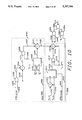
- FIG. 11 shows a detailed block diagram of the loop filter circuit of FIG. 8.
- FIG. 1 shows a block diagram of a typical environment of the invention.
- a computer system 100 contains a processing element 102 which communicates to other elements of the computer system 100 over a system bus 104.
- a keyboard 106 and a display 108 allow a user of the computer system 100 to communicate with the computer system 100.
- a memory 110 contains programs and data which cause the computer system 100 to perform operations desired by the user.
- a disk data storage system 112 is connected to the system bus 104 for storing data and programs within the computer system 100.
- a disk controller 114 within the disk device 112 communicates to the system bus 104 and controls the operations of a disk drive 118, possibly in conjunction with a local microprocessor (not shown) within the disk data storage system 112.
- the disk drive 118 performs the storage function, typically storing the data on magnetic media.
- a bus 116 connects the disk controller 114 to the disk drive 118, specifically connecting to a write channel 120 to write data onto the disk through write heads and amplifiers 128. When data is being read from the disk through the read head and amplifiers 128 the data comes back through the read channel 122 which contains the gain control circuit of the present invention.
- the read and write heads may be physically the same heads.
- the data first passes through the analog section 126 of the read channel 122 and then through the digital section 124 of the read channel 122 before being sent on the bus 116 to the disk controller 114. After being processed by the disk controller 114, the data is then sent over the system bus 104 to the memory 110 and/or the processing element 102.
- the disk controller 114 also connects to other circuits, not shown, within the disk drive 118, such as a circuit which moves the read/write heads over the surface of the data storage media.
- the gain control circuit of the present invention can be used for controlling the amplitude of pulses within data received from a transmission line, such as a telephone line or local area network, in a data communications receiver. It may also be used in any other device that must time and detect pulses within a signal.
- FIG. 2 shows a block diagram of the analog circuitry 126 of the read channel 122.
- a read head when a read head is passing over a track of the data storage medium, it picks up a signal which is amplified by a preamplifier, not shown. After this preamplification, the signal 201 is passed to a variable gain amplifier 202. The signal is further amplified by the variable gain amplifier 202 and passed through an analog multiplexer 203 and then to an analog equalizer circuit 204, which filters the signal as desired, for example, so as to remove unwanted high frequencies and shape the remaining spectrum. The output of the analog equalizer 204 is connected to an Analog to Digital converter 206.
- the A to D converter 206 converts the analog signal into a sequence of digital values, providing six bits of digital information per sample in the preferred embodiment, and then the data is passed to a register/de-multiplexer 207.
- the digital section 124 of the read channel 122 processes two samples in parallel.
- the register/de-multiplexer 207 stores every other sample taken by the A to D converter 206.
- the data from the two samples is passed to the data bus 230.
- the bus 230 is clocked by a single half-frequency clock signal.
- the timing necessary for converting the data, also called taking a sample, in the A to D converter 206 is supplied by a variable frequency oscillator 222 which is controlled by the output of a digital to analog converter (DAC) 220.
- the input to the DAC 220 comes from the digital section of the read channel 124 as timing feedback signal 234.
- the gain or attenuation of the variable gain amplifier 202 is controlled through a gain feedback signal 232 which originates in the digital portion 124 of the read channel 122.
- the gain feedback signal 232 is input to a summing junction 210 which has a coarse gain control value as its other input.
- the coarse gain control can be set by the disk controller 114, or a local microprocessor (not shown) within the disk drive, to provide a nominal gain level which is then adjusted up or down by the gain feedback signal 232.
- the feedback signal is sent to a digital to analog converter 212 and then to a filter 214.
- the coarse gain 208 and gain feedback 232 may each be converted to analog values by separate DACs and the summing 210 done on the analog signal output of the DACs. Because of the nature of many digital to analog converters, the output of the DAC 212 may contain glitches when it is changing values. Therefore, the filter 214 may be necessary to remove these glitches in the feedback signal. After being filtered, the signal is exponentiated by the exponential converter block 216 and then connected to the variable gain amplifier 202. This conversion makes the small-signal gain control dynamics independent of the input signal amplitude.
- FIG. 3 shows a block diagram of the digital section 124 of the read channel 122 (FIG. 1).
- the digital data signal 230 from FIG. 2 is input to a delay circuit 304 and a digital filter circuit 302.
- the outputs of these two circuits are connected to multiplexers 306 and 316, whose outputs are connected to multiplexers 310 and 318 respectively.
- Multiplexers 310 and 318 also receive signal 230.
- Multiplexers 306 and 316 may be selected independently, however, multiplexers 310 and 318 are always selected together. In this manner, either the digital data signal 230 or the filtered/delayed signals may be selected for input to both a pulse detector 312 and a gain control circuit 330.
- the filter signal is selected for either the pulse detector 312 or the gain control circuit 330, either the filter signal or the delay signal must be selected for input to the other of these circuits.
- the filter 302 inserts a delay into the digital data signal 230, so if one circuit selects the filtered signal, the other circuit input must be delay-compensated by selecting the delayed signal from circuit 304 or by also selecting the filter signal from filter 302.
- the output of the pulse detector 312 is connected to a gain control circuit 330 which provides the gain feedback signal 232 that connects to FIG. 2.
- the output of the pulse detector 312 is also connected to the timing recover circuit 328 whose output 234 connects to the digital to analog converter 220of FIG. 2.
- the output of the pulse detector 312 may also be connected to a sync mark detector 322 and an RLL decoder 320, as shown in FIG. 3, or a more sophisticated data detector (not shown) may be connected to the sync mark detector 322 and the RLL decoder 320.
- the output of the RLL decoder 320 and the sync mark detector 322 are connected to the disk controller 114 (FIG. 1) through the bus 116.
- the pulse detector 312, the timing recovery circuit 328, and the gain control circuit 330 are designed to process pulses using one of two types of sampling methods, selected by the user.
- the first sampling method is called center sampling wherein one of the samples taken will arrive at or near the center, or peak, of a pulse as shown in FIG. 4.
- the location of the sampling is controlled by the timing recovery block 328.
- the timing recovery block 328 will adjust the timing of the VFO 222 (FIG. 2) such that two consecutive samples are taken wherein one of the two samples appears on one side of the peak of the pulse and the other of the two samples appears on the other side of the peak as shown in FIG. 5.
- the user of the system determines whether center sampling or side sampling is used by setting a bit in a control register through the interface 116 (FIG. 1).
- sampling can occur during two different time segments within a data record being read from the disk media.
- acquisition mode because it occurs when the gain control and timing control are acquiring the gain and timing relationships of the pulses. This occurs when the read head is passing a preamble portion of the data record which always has a known data pattern to facilitate acquisition of the timing and gain.
- tracking mode a different mode is used for the pulse detector and timing recovery, called tracking mode, since data has an irregular and a priori unknown pattern of pulses.
- the pulse detector, timing recovery circuits, and gain control circuits are designed to process pulses under four separate conditions.
- the first condition is acquisition mode using side sampling
- the second is acquisition mode using center sampling
- third is tracking mode using side sampling
- fourth is tracking mode using center sampling.
- FIG. 4 shows a signal waveform of an isolated pulse and illustrates center sampling of the pulse.
- a signal waveform 402 is shown having four samples taken with the sample identified by reference 412, at time n, being the most recent sample.
- Sample 410, at time n-1 is the sample just prior to the most recent sample, sample 408 is the next previous sample and sample 406 is the oldest of the four samples shown.
- Negative pulses would appear as a mirror image of FIG. 4.
- the samples taken of the pulse are also identified as "a”, "b”, "1", and "c”.
- Sample “a” occurs at time n-3 of each pulse
- sample “b” occurs at time n-2 of each pulse
- sample "1” occurs at time n-1 of each pulse
- sample “c” occurs at time n of each pulse.
- the sample labeled “1” is so labeled because the gain control circuit adjusts the level of this sample to a nominal value of 1.
- FIG. 5 shows a signal waveform of an isolated pulse and illustrates side sampling of the pulse.
- a signal waveform 502 is shown as a positive level above a baseline 503.
- Four samples are shown, with the most recent sample being sample 510.
- Sample 508 is the sample previous to the most recent, 506 is the next previous sample and sample 504 is the oldest of the four samples shown. These samples are also identified by the time references n through n-3.
- FIGS. 6 and 7 show waveforms and sample times for a typical pulse for side and center sampling, respectively, and will be used to illustrate the equations shown in Table 1.
- a waveform 602 is shown with side sampling mode, with the four samples of the waveforms, "a”, “b”, “1”, and “c", being identified for the value of the waveform at sample times n-3, n-2, n-1, and n, respectively.
- pulses can never occur at two successive sampling times, thus pulses must be separated by at least two sample times. Therefore, the pulse illustrated by dashed line 604 is the closest a pulse could occur prior to the pulse 602 and the pulse identified by dashed line 606 is the earliest another pulse could occur after the pulse 602.
- the gain error for side sampled is determined by adding the samples y n-1 and y n-2 , multiplying by -1 if the pulse detected at time n is a positive pulse (as indicated by the sign of y n-1 ), and adding the gain set point g a for acquisition mode or g t for tracking mode. Since y n-2 is nominally equal to 1, the gain set point g a or g t should nominally be set to (1+b).
- pulse 604 Since pulse 604 might have occurred two sample times earlier than pulse 602, and pulse 606 might occur two sample times later, the effects of these pulses must be considered in the equations.
- the term "-(a+c)P n-2 " accounts for the ISI effects of the pulse 604 and the pulse 606.
- Sample "c" of pulse 604 occurs at the same time as sample "b" of pulse 602. Therefore, if there was a peak detected at time n-2, i.e. p n-2 is one, the gain is corrected by subtracting a constant value c to offset the "c" sample of pulse 604. This constant value is determined by calibration of the device and is input to the circuit through the interface 116 (FIG. 1).
- a pulse could occur two sample times after pulse 602, represented in FIG. 6 by pulse 606.
- the "a" sample occurs at the same time as the "1" sample of pulse 602. Therefore, the gain error is corrected by subtracting a constant a if there is a pulse at time n+2, i.e. if P 2+2 is one. Rather than wait two additional sample times to determine whether a pulse occurs at time n+2 before making a gain error measurement, subtraction of the constant is simply delayed two clock times. This is possible because of the small effect resulting from the pulse 606.
- This constant value, a is also determined by calibration of the device and input to the circuit through the interface 116 (FIG. 1).
- FIG. 7 shows waveforms when center sampling is being used.
- Table 1 shows the center sampling equations, and the center sampled equations are very similar to side sampled equations, except that in center sampling only the "1" sample of each pulse is used to determine gain error. Therefore, the center sampled equations remove the y n-2 term from the side sampled equations. Thus for center sampling the nominal value of the gain set point g a or g t is 1.
- the center sampled equations incorporate the same type of adjustment for ISI that was incorporated into the side sampled equations.
- pulses 704, 706, and 708 can overlap the pulse 702, and if this occurs, the "a" sample of pulse 706 overlaps the "1" sample of pulse 702. Therefore, the center sampled tracking equation adds the term "-a*P n-2 " to compensate for the pulse 706, where a is the same constant described for the side sampling equations.
- FIG. 8 shows a block diagram of the gain control circuit 330 of FIG. 3.
- a gain error detector circuit 802 receives the input digital values over the bus 320, and the output 314 of the pulse detector.
- the gain error detector 802 applies the equations of Table 1 to create an amplitude error signal 810 which is connected to a loop filter 804.
- the loop filter 804 divides the amplitude error by a programmable value and integrates the result before returning the VGAC signal 232 to the circuit of FIG. 2.
- FIGS. 9 and 10 show a detailed block diagram of the gain error detector of FIG. 8. Referring now to FIG. 9, the circuit surrounded by dashed line 901 partially solves the equations of table 1, to produce the result of:
- AND gate 902 inputs the "c” term to the adder 904 if side sampling is being used, and the adder 904 combines the "c” and “a” terms, or outputs only the "a” term if center sampling is being used.
- AND gate 906 passes the output of adder 904 to adder 910 if there was a pulse at time n-2.
- Multiplexer 908 selects the g a term or g t term, depending upon whether the system is in acquisition or tracking mode, and adder 910 subtracts this term from the output of AND gate 906 and sends an output 926 to an adder 918.
- Multiplexer 914 selects the sum of Y n-1 and Y n-2 if side sampling is being used, or just Y n-1 if center sampling is being used. This value is made negative by XOR gate 916 and the input 932 to adder 918 if the sign of Y n-1 is negative as indicated by bit 5 of Y n-1 (since 6-bit two's complement arithmetic is being used). Adder 918 completes the equation and sends the result to FIG. 10 as signal 930.
- FIG. 10 solves the same equations, however, it solves them for the previous sample.
- the circuit of dashed line 1001 performs the same function as the circuit in dashed line 901
- the circuit in dashed line 1000 performs the same function as the circuit in dashed line 900, however, both work with the previous sample.
- the difference between the circuits of FIGS. 9 and 10 is in the inputs 946 (1046), 942 (1042) and 944 (1044) where FIG. 9 uses the current sample and FIG. 10 uses the previous sample.
- NAND gates 1062, 1064, and 1066 combine the results of FIGS. 9 and 10, depending upon whether a pulse occurred in the previous or current sample. Because of the data encoding method used for recording data, two successive pulses cannot occur, so NAND gates 1062, 1064, and 1066 select one or the other, or neither in the case where no pulse occurred in either sample.
- the output of FIG. 10 is the amplitude error 810 discussed above, which is connected to the loop filter 804.
- FIG. 11 shows a block diagram of the loop filter 804.
- the circuit surrounded by dashed line 1100 multiplies the amplitude error 810 by a loop filter coefficient value, and the circuit surrounded by dashed line 1101 accumulates the adjusted amplitude error into a register without letting the value overflow or underflow.
- Multiplexer 1140 selects either the acquisition or tracking loop filter coefficient.
- Register 1102 stores the amplitude error signal 810.
- Divide by two circuit 1104 and adder 1106 multiply the amplitude error signal by 3/2, and multiplexer 1108 selects either the amplitude error or the 3/2 value, depending upon bit zero of the loop filter coefficient selected by multiplexer 1140.
- Multiplexer circuits 1110, 1112, 1114, 1116, 1118, 1120, and 1122 further multiply the output of multiplexer 1108 by 1/128, 1/64, 1/32, 1/16, 1/8, 1/4 or 1/2, based upon bits three, two, and one of the loop filter coefficient.
- one input to multiplexer 1116 allows the amplitude error to be set to zero, to allow the gain to remain constant.
- Register 1124 stores the adjusted amplitude error for an additional clock cycle before passing the value to adder 1126.
- Adder 1126 adjusts the value of register 1130 by the output of register 1124, and SAT circuit 1128 ensures that the output of adder 1126 does not overflow or underflow. Instead of overflowing or underflowing, the SAT circuit 1128 causes the adder 1126 output to saturate.
- the output of register 1130 is the gain feedback signal input to the adder 210 of FIG. 2.
Landscapes
- Engineering & Computer Science (AREA)
- Signal Processing (AREA)
- Signal Processing For Digital Recording And Reproducing (AREA)
Abstract
Description
-SGN(Y.sub.n-1)(Y.sub.n-1 +Y.sub.n-2) or -SGN(Y.sub.n-1)Y.sub.n-1
                                  TABLE 1
__________________________________________________________________________
Acquistion             Tracking
__________________________________________________________________________
Side --SGN(y.sub.n-1)*(y.sub.n-1 + y.sub.n-2) + g.sub.a
                       --SGN(y.sub.n-1)*(y.sub.n-1 + y.sub.n-2) + g.sub.t
                       -
Sampled
     (a + c)P.sub.n-2  (a + c)*P.sub.n-2
Center
     --SGN(y.sub.n-1)*(y.sub.n-1) +g.sub.a - a*P.sub.n-2
                       --SGN(y.sub.n-1)*(y.sub.n-1) + g.sub.t
                       - a*P.sub.n-2
Sampled
__________________________________________________________________________
Claims (17)
Priority Applications (5)
| Application Number | Priority Date | Filing Date | Title |
|---|---|---|---|
| US08/012,049 US5297184A (en) | 1993-02-01 | 1993-02-01 | Gain control circuit for synchronous waveform sampling |
| PCT/US1994/001008 WO1994018773A1 (en) | 1993-02-01 | 1994-01-27 | Gain control circuit for synchronous waveform sampling |
| JP6518110A JPH08506707A (en) | 1993-02-01 | 1994-01-27 | Gain control circuit for synchronous waveform sampling |
| EP94906719A EP0681771A4 (en) | 1993-02-01 | 1994-01-27 | Gain control circuit for synchronous waveform sampling. |
| SG1996004701A SG50549A1 (en) | 1993-02-01 | 1994-01-27 | Gain control circuit for synchronous wafeform sampling |
Applications Claiming Priority (1)
| Application Number | Priority Date | Filing Date | Title |
|---|---|---|---|
| US08/012,049 US5297184A (en) | 1993-02-01 | 1993-02-01 | Gain control circuit for synchronous waveform sampling |
Publications (1)
| Publication Number | Publication Date |
|---|---|
| US5297184A true US5297184A (en) | 1994-03-22 |
Family
ID=21753129
Family Applications (1)
| Application Number | Title | Priority Date | Filing Date |
|---|---|---|---|
| US08/012,049 Expired - Lifetime US5297184A (en) | 1993-02-01 | 1993-02-01 | Gain control circuit for synchronous waveform sampling |
Country Status (5)
| Country | Link |
|---|---|
| US (1) | US5297184A (en) |
| EP (1) | EP0681771A4 (en) |
| JP (1) | JPH08506707A (en) |
| SG (1) | SG50549A1 (en) |
| WO (1) | WO1994018773A1 (en) |
Cited By (28)
| Publication number | Priority date | Publication date | Assignee | Title |
|---|---|---|---|---|
| WO1994018670A1 (en) * | 1993-02-01 | 1994-08-18 | Cirrus Logic, Inc. | Synchronous read channel |
| US5459757A (en) * | 1994-09-21 | 1995-10-17 | Seagate Technology, Inc. | Timing and gain control circuit for a PRML read channel |
| US5585975A (en) * | 1994-11-17 | 1996-12-17 | Cirrus Logic, Inc. | Equalization for sample value estimation and sequence detection in a sampled amplitude read channel |
| EP0777211A2 (en) | 1995-12-05 | 1997-06-04 | Cirrus Logic, Inc. | A magnetic disk sampled amplitude read channel employing interpolated timing recovery for synchronous detection of embedded servo data |
| EP0771000A3 (en) * | 1995-10-27 | 1997-08-20 | Toshiba Kk | Optical disk reproducing apparatus equipped with variable gain amplifier capable of adjusting amplitude of reproduction signal |
| US5677962A (en) * | 1995-01-26 | 1997-10-14 | Sony Corporation | Hybrid analog and digital amplifier with a delayed step change in the digital gain |
| US5796535A (en) * | 1995-05-12 | 1998-08-18 | Cirrus Logic, Inc. | Sampled amplitude read channel employing a user data frequency synthesizer and a servo data frequency synthesizer |
| US5862157A (en) * | 1997-02-24 | 1999-01-19 | Texas Instruments Incorporated | Method and circuitry for monitoring a digital channel |
| US5986830A (en) * | 1997-07-30 | 1999-11-16 | Cirrus Logic, Inc. | Read/write channel write precompensation system and method using one or more delay clocks |
| US5987562A (en) * | 1996-03-08 | 1999-11-16 | Texas Instruments Incorporated | Waveform sampler and method for sampling a signal from a read channel |
| US5990814A (en) * | 1997-09-05 | 1999-11-23 | Cirrus Logic, Inc. | Method and circuit for calibration of flash analog to digital converters |
| US5990707A (en) * | 1997-09-05 | 1999-11-23 | Cirrus Logic, Inc. | Method and system for sliced integration of flash analog to digital converters in read channel circuits |
| US6009549A (en) * | 1997-05-15 | 1999-12-28 | Cirrus Logic, Inc. | Disk storage system employing error detection and correction of channel coded data, interpolated timing recovery, and retroactive/split-segment symbol synchronization |
| US6018554A (en) * | 1996-05-17 | 2000-01-25 | Texas Instruments Incorporated | Automatic gain control circuit and method for full gain restart |
| US6028727A (en) * | 1997-09-05 | 2000-02-22 | Cirrus Logic, Inc. | Method and system to improve single synthesizer setting times for small frequency steps in read channel circuits |
| US6069866A (en) * | 1997-10-23 | 2000-05-30 | Cirrus Logic, Inc. | System and method for coarse gain control of wide band amplifiers |
| US6078444A (en) * | 1995-05-12 | 2000-06-20 | Cirrus Logic, Inc. | Read channel auxiliary high precision data conversion |
| US6084538A (en) * | 1997-09-05 | 2000-07-04 | Cirrus Logic, Inc. | Offset calibration of a flash ADC array |
| US6091942A (en) * | 1996-12-02 | 2000-07-18 | Motorola, Inc. | Self gain aligning circuit and method |
| US6111712A (en) * | 1998-03-06 | 2000-08-29 | Cirrus Logic, Inc. | Method to improve the jitter of high frequency phase locked loops used in read channels |
| US6111710A (en) * | 1997-06-25 | 2000-08-29 | Cirrus Logic, Inc. | Asynchronous/synchronous gain control for interpolated timing recovery in a sampled amplitude read channel |
| US6141169A (en) * | 1997-10-23 | 2000-10-31 | Cirrus Logic, Inc. | System and method for control of low frequency input levels to an amplifier and compensation of input offsets of the amplifier |
| US6246723B1 (en) | 1998-05-04 | 2001-06-12 | Cirrus Logic, Inc. | Sampled amplitude read channel employing early-decisions from a trellis sequence detector for sampling value estimation |
| EP1126457A2 (en) * | 2000-02-14 | 2001-08-22 | STMicroelectronics, Inc. | A circuit and method for controlling the gain of an amplifier |
| EP1126456A2 (en) * | 2000-02-14 | 2001-08-22 | STMicroelectronics, Inc. | A circuit and method for controlling the gain of an amplifier based on the sum of samples of the amplified signal |
| US6417730B1 (en) | 2000-11-29 | 2002-07-09 | Harris Corporation | Automatic gain control system and related method |
| US6677823B2 (en) | 2001-02-28 | 2004-01-13 | Andrew Corporation | Gain compensation circuit using a variable offset voltage |
| CN100423120C (en) * | 2002-04-23 | 2008-10-01 | 皇家飞利浦电子股份有限公司 | Interference-free lms-based adaptive asynchronous receiver |
Citations (6)
| Publication number | Priority date | Publication date | Assignee | Title |
|---|---|---|---|---|
| US4625240A (en) * | 1984-07-25 | 1986-11-25 | Eeco, Inc. | Adaptive automatic gain control |
| US4634896A (en) * | 1984-11-30 | 1987-01-06 | Storage Technology Corporation | Method and apparatus for qualifying valid data peaks in a read/write channel |
| US4750058A (en) * | 1986-08-05 | 1988-06-07 | International Business Machines Corporation | Gain control circuitry for readback apparatus in a PRML magnetic recording system |
| US4829593A (en) * | 1986-03-18 | 1989-05-09 | Nec Corporation | Automatic gain control apparatus |
| US4864244A (en) * | 1987-09-21 | 1989-09-05 | Nec Corporation | Stepped square-QAM demodulator utilizing all signal points to generate control signals |
| US5184349A (en) * | 1991-01-16 | 1993-02-02 | Motorola, Inc. | Amplitude control of a burst signal in a receiver |
Family Cites Families (1)
| Publication number | Priority date | Publication date | Assignee | Title |
|---|---|---|---|---|
| US5068628A (en) * | 1990-11-13 | 1991-11-26 | Level One Communications, Inc. | Digitally controlled timing recovery loop |
-
1993
- 1993-02-01 US US08/012,049 patent/US5297184A/en not_active Expired - Lifetime
-
1994
- 1994-01-27 JP JP6518110A patent/JPH08506707A/en active Pending
- 1994-01-27 WO PCT/US1994/001008 patent/WO1994018773A1/en not_active Application Discontinuation
- 1994-01-27 SG SG1996004701A patent/SG50549A1/en unknown
- 1994-01-27 EP EP94906719A patent/EP0681771A4/en not_active Withdrawn
Patent Citations (6)
| Publication number | Priority date | Publication date | Assignee | Title |
|---|---|---|---|---|
| US4625240A (en) * | 1984-07-25 | 1986-11-25 | Eeco, Inc. | Adaptive automatic gain control |
| US4634896A (en) * | 1984-11-30 | 1987-01-06 | Storage Technology Corporation | Method and apparatus for qualifying valid data peaks in a read/write channel |
| US4829593A (en) * | 1986-03-18 | 1989-05-09 | Nec Corporation | Automatic gain control apparatus |
| US4750058A (en) * | 1986-08-05 | 1988-06-07 | International Business Machines Corporation | Gain control circuitry for readback apparatus in a PRML magnetic recording system |
| US4864244A (en) * | 1987-09-21 | 1989-09-05 | Nec Corporation | Stepped square-QAM demodulator utilizing all signal points to generate control signals |
| US5184349A (en) * | 1991-01-16 | 1993-02-02 | Motorola, Inc. | Amplitude control of a burst signal in a receiver |
Non-Patent Citations (12)
| Title |
|---|
| Cideciyan et al., "A PRML System for Digital Magnetic Recording", IEEE Journal on Selected Areas in Communications, vol. 10, No. 1, Jan. 1992. |
| Cideciyan et al., A PRML System for Digital Magnetic Recording , IEEE Journal on Selected Areas in Communications, vol. 10, No. 1, Jan. 1992. * |
| Coker et al., "Implementation of PRML in a Rigid Disk Drive", IEEE Trnasactions on Magnetics, vol. 27, No. 6, Nov. 1991. |
| Coker et al., Implementation of PRML in a Rigid Disk Drive , IEEE Trnasactions on Magnetics, vol. 27, No. 6, Nov. 1991. * |
| Hong et al., "An Experimental 180 Mb/sec PRML Channel for Magnetic Recording", IEEE Transactions on Magnetics, vol. 27, No. 6, Nov. 1991. |
| Hong et al., An Experimental 180 Mb/sec PRML Channel for Magnetic Recording , IEEE Transactions on Magnetics, vol. 27, No. 6, Nov. 1991. * |
| Howell et al., "Error Rate Performance of Experimental Gigabit per Square Inch Recording Components", IBM Research Report, Mar. 1990. |
| Howell et al., Error Rate Performance of Experimental Gigabit per Square Inch Recording Components , IBM Research Report, Mar. 1990. * |
| Kato et al., "An Adaptive Equalizer for R-DAT", IEEE Transactions on Consumer Electronics, vol. 35, No. 3, Aug. 1989. |
| Kato et al., An Adaptive Equalizer for R DAT , IEEE Transactions on Consumer Electronics, vol. 35, No. 3, Aug. 1989. * |
| Schmerbeck et al., "A 27MHz Mixed Analog/Digital Magnetic Recording Channel DSP Using Partial Response Signalling with maximum Likelihood Detection", IEEE International Solid State Circuits Conference, 1991. |
| Schmerbeck et al., A 27MHz Mixed Analog/Digital Magnetic Recording Channel DSP Using Partial Response Signalling with maximum Likelihood Detection , IEEE International Solid State Circuits Conference, 1991. * |
Cited By (36)
| Publication number | Priority date | Publication date | Assignee | Title |
|---|---|---|---|---|
| WO1994018670A1 (en) * | 1993-02-01 | 1994-08-18 | Cirrus Logic, Inc. | Synchronous read channel |
| US5459757A (en) * | 1994-09-21 | 1995-10-17 | Seagate Technology, Inc. | Timing and gain control circuit for a PRML read channel |
| US5585975A (en) * | 1994-11-17 | 1996-12-17 | Cirrus Logic, Inc. | Equalization for sample value estimation and sequence detection in a sampled amplitude read channel |
| US5677962A (en) * | 1995-01-26 | 1997-10-14 | Sony Corporation | Hybrid analog and digital amplifier with a delayed step change in the digital gain |
| US6078444A (en) * | 1995-05-12 | 2000-06-20 | Cirrus Logic, Inc. | Read channel auxiliary high precision data conversion |
| US5796535A (en) * | 1995-05-12 | 1998-08-18 | Cirrus Logic, Inc. | Sampled amplitude read channel employing a user data frequency synthesizer and a servo data frequency synthesizer |
| US5966258A (en) * | 1995-05-12 | 1999-10-12 | Cirrus Logic, Inc. | Asynchronous/synchronous digital gain control loop in a sampled amplitude read channel |
| US6646822B1 (en) | 1995-05-12 | 2003-11-11 | Cirrus Logic, Inc. | Sampled amplitude read channel employing pipelined reads to reduce the gap between sectors |
| US6108151A (en) * | 1995-05-12 | 2000-08-22 | Cirrus Logic, Inc. | Sampled amplitude read channel for reading user data and embedded servo data from a magnetic medium |
| US5784356A (en) * | 1995-10-27 | 1998-07-21 | Kabushiki Kaisha Toshiba | Optical disk reproducing apparatus equipped with variable gain amplifier capable of adjusting amplitude of reproduction signal |
| EP0771000A3 (en) * | 1995-10-27 | 1997-08-20 | Toshiba Kk | Optical disk reproducing apparatus equipped with variable gain amplifier capable of adjusting amplitude of reproduction signal |
| EP0777211A2 (en) | 1995-12-05 | 1997-06-04 | Cirrus Logic, Inc. | A magnetic disk sampled amplitude read channel employing interpolated timing recovery for synchronous detection of embedded servo data |
| US5987562A (en) * | 1996-03-08 | 1999-11-16 | Texas Instruments Incorporated | Waveform sampler and method for sampling a signal from a read channel |
| US6018554A (en) * | 1996-05-17 | 2000-01-25 | Texas Instruments Incorporated | Automatic gain control circuit and method for full gain restart |
| US6091942A (en) * | 1996-12-02 | 2000-07-18 | Motorola, Inc. | Self gain aligning circuit and method |
| US5862157A (en) * | 1997-02-24 | 1999-01-19 | Texas Instruments Incorporated | Method and circuitry for monitoring a digital channel |
| US6009549A (en) * | 1997-05-15 | 1999-12-28 | Cirrus Logic, Inc. | Disk storage system employing error detection and correction of channel coded data, interpolated timing recovery, and retroactive/split-segment symbol synchronization |
| US6111710A (en) * | 1997-06-25 | 2000-08-29 | Cirrus Logic, Inc. | Asynchronous/synchronous gain control for interpolated timing recovery in a sampled amplitude read channel |
| US5986830A (en) * | 1997-07-30 | 1999-11-16 | Cirrus Logic, Inc. | Read/write channel write precompensation system and method using one or more delay clocks |
| US6084538A (en) * | 1997-09-05 | 2000-07-04 | Cirrus Logic, Inc. | Offset calibration of a flash ADC array |
| US5990814A (en) * | 1997-09-05 | 1999-11-23 | Cirrus Logic, Inc. | Method and circuit for calibration of flash analog to digital converters |
| US6028727A (en) * | 1997-09-05 | 2000-02-22 | Cirrus Logic, Inc. | Method and system to improve single synthesizer setting times for small frequency steps in read channel circuits |
| US5990707A (en) * | 1997-09-05 | 1999-11-23 | Cirrus Logic, Inc. | Method and system for sliced integration of flash analog to digital converters in read channel circuits |
| US6141169A (en) * | 1997-10-23 | 2000-10-31 | Cirrus Logic, Inc. | System and method for control of low frequency input levels to an amplifier and compensation of input offsets of the amplifier |
| US6069866A (en) * | 1997-10-23 | 2000-05-30 | Cirrus Logic, Inc. | System and method for coarse gain control of wide band amplifiers |
| US6111712A (en) * | 1998-03-06 | 2000-08-29 | Cirrus Logic, Inc. | Method to improve the jitter of high frequency phase locked loops used in read channels |
| US6246723B1 (en) | 1998-05-04 | 2001-06-12 | Cirrus Logic, Inc. | Sampled amplitude read channel employing early-decisions from a trellis sequence detector for sampling value estimation |
| US6867941B1 (en) | 2000-02-14 | 2005-03-15 | Stmicroelectronics, Inc. | Circuit and method for controlling the gain of an amplifier based on the sum of samples of the amplified signal |
| EP1126456A2 (en) * | 2000-02-14 | 2001-08-22 | STMicroelectronics, Inc. | A circuit and method for controlling the gain of an amplifier based on the sum of samples of the amplified signal |
| US6778345B1 (en) * | 2000-02-14 | 2004-08-17 | Stmicroelectronics, Inc. | Circuit and method for controlling the gain of an amplifier |
| EP1126457A2 (en) * | 2000-02-14 | 2001-08-22 | STMicroelectronics, Inc. | A circuit and method for controlling the gain of an amplifier |
| EP1126456A3 (en) * | 2000-02-14 | 2005-08-24 | STMicroelectronics, Inc. | A circuit and method for controlling the gain of an amplifier based on the sum of samples of the amplified signal |
| EP1126457A3 (en) * | 2000-02-14 | 2005-08-24 | STMicroelectronics, Inc. | A circuit and method for controlling the gain of an amplifier |
| US6417730B1 (en) | 2000-11-29 | 2002-07-09 | Harris Corporation | Automatic gain control system and related method |
| US6677823B2 (en) | 2001-02-28 | 2004-01-13 | Andrew Corporation | Gain compensation circuit using a variable offset voltage |
| CN100423120C (en) * | 2002-04-23 | 2008-10-01 | 皇家飞利浦电子股份有限公司 | Interference-free lms-based adaptive asynchronous receiver |
Also Published As
| Publication number | Publication date |
|---|---|
| EP0681771A1 (en) | 1995-11-15 |
| JPH08506707A (en) | 1996-07-16 |
| WO1994018773A1 (en) | 1994-08-18 |
| SG50549A1 (en) | 1998-08-20 |
| EP0681771A4 (en) | 1997-12-10 |
Similar Documents
| Publication | Publication Date | Title |
|---|---|---|
| US5297184A (en) | Gain control circuit for synchronous waveform sampling | |
| US5359631A (en) | Timing recovery circuit for synchronous waveform sampling | |
| EP0109837B1 (en) | Digital data detecting apparatus | |
| US6430238B1 (en) | Digital servo channel for recording apparatus | |
| US5329554A (en) | Digital pulse detector | |
| EP0320022B1 (en) | DC Restoration circuit for restoring and compensating for low frequency component lost in digital signal transmission system | |
| US5970091A (en) | Equalizer having a processing unit for selecting a coefficient out of a coefficient table | |
| US5239423A (en) | Method and apparatus for recovering digital signals from recorded reproductions of digital signals | |
| US5163003A (en) | Apparatus and method for reading from and writing to a magnetic recording medium | |
| KR100243218B1 (en) | Data decoding apparatus and the method | |
| US4637006A (en) | Apparatus for producing digital information from a transmission medium | |
| US5892474A (en) | Clock phase acquisition/tracking device and phase acquisition method | |
| EP1098312B1 (en) | Waveform equalizer | |
| US6853509B2 (en) | Acquisition signal error estimator | |
| US6304400B1 (en) | Signal dropout compensation | |
| US5982310A (en) | Digital signal processing apparatus | |
| EP0700042A1 (en) | Signal processing device | |
| US6469851B1 (en) | Acquisition signal error estimator | |
| JP3917317B2 (en) | Equalization / phase control system and disk storage device including the same | |
| US6977875B1 (en) | Tracking system for recording/reading a data medium and recording medium | |
| JP2638219B2 (en) | Magnetic recording / reproducing circuit | |
| KR100300953B1 (en) | Digital data recording / playback apparatus and method | |
| KR19980014888A (en) | Digital magnetic recording and reproducing apparatus | |
| JP3225588B2 (en) | Digital signal regeneration circuit | |
| JPS63113982A (en) | Digital signal detecting circuit |
Legal Events
| Date | Code | Title | Description |
|---|---|---|---|
| AS | Assignment |
Owner name: CIRRUS LOGIC, INC., CALIFORNIA Free format text: ASSIGNMENT OF ASSIGNORS INTEREST;ASSIGNORS:BEHRENS, RICHARD T.;DUDLEY, TRENT;GLOVER, NEAL;REEL/FRAME:006535/0146 Effective date: 19930201 |
|
| STCF | Information on status: patent grant |
Free format text: PATENTED CASE |
|
| AS | Assignment |
Owner name: BANK OF AMERICA NATIONAL TRUST & SAVINGS ASSOCIATI Free format text: SECURITY INTEREST;ASSIGNOR:CIRRUS LOGIC, INC.;REEL/FRAME:007986/0917 Effective date: 19960430 |
|
| FPAY | Fee payment |
Year of fee payment: 4 |
|
| SULP | Surcharge for late payment | ||
| FEPP | Fee payment procedure |
Free format text: PAYOR NUMBER ASSIGNED (ORIGINAL EVENT CODE: ASPN); ENTITY STATUS OF PATENT OWNER: LARGE ENTITY |
|
| FPAY | Fee payment |
Year of fee payment: 8 |
|
| AS | Assignment |
Owner name: CIRRUS LOGIC INTERNATIONAL LTD., BERMUDA Free format text: DEED OF DISCHARGE;ASSIGNOR:BANK OF AMERICA NATIONAL TRUST SAVINGS ASSOCIATION;REEL/FRAME:013782/0435 Effective date: 19970630 |
|
| FPAY | Fee payment |
Year of fee payment: 12 |