US5255746A - Adjustable mandrel hanger assembly - Google Patents
Adjustable mandrel hanger assembly Download PDFInfo
- Publication number
- US5255746A US5255746A US07/927,025 US92702592A US5255746A US 5255746 A US5255746 A US 5255746A US 92702592 A US92702592 A US 92702592A US 5255746 A US5255746 A US 5255746A
- Authority
- US
- United States
- Prior art keywords
- load
- mandrel
- collet
- grooves
- ring
- Prior art date
- Legal status (The legal status is an assumption and is not a legal conclusion. Google has not performed a legal analysis and makes no representation as to the accuracy of the status listed.)
- Expired - Lifetime
Links
- 230000013011 mating Effects 0.000 claims abstract 4
- 239000012530 fluid Substances 0.000 claims description 4
- WYTGDNHDOZPMIW-RCBQFDQVSA-N alstonine Natural products C1=CC2=C3C=CC=CC3=NC2=C2N1C[C@H]1[C@H](C)OC=C(C(=O)OC)[C@H]1C2 WYTGDNHDOZPMIW-RCBQFDQVSA-N 0.000 claims 2
- 230000008602 contraction Effects 0.000 claims 2
- 230000002040 relaxant effect Effects 0.000 claims 1
- 238000005553 drilling Methods 0.000 description 4
- 238000009434 installation Methods 0.000 description 1
- 238000010008 shearing Methods 0.000 description 1
- 239000007787 solid Substances 0.000 description 1
Images


Classifications
-
- E—FIXED CONSTRUCTIONS
- E21—EARTH OR ROCK DRILLING; MINING
- E21B—EARTH OR ROCK DRILLING; OBTAINING OIL, GAS, WATER, SOLUBLE OR MELTABLE MATERIALS OR A SLURRY OF MINERALS FROM WELLS
- E21B33/00—Sealing or packing boreholes or wells
- E21B33/02—Surface sealing or packing
- E21B33/03—Well heads; Setting-up thereof
- E21B33/04—Casing heads; Suspending casings or tubings in well heads
- E21B33/043—Casing heads; Suspending casings or tubings in well heads specially adapted for underwater well heads
Definitions
- This invention relates in general to a system for tensioning a section of casing extending between a subsea housing and a surface wellhead located on an offshore platform, and in particular to a system utilizing an adjustable mandrel.
- a wellhead housing In one type of offshore drilling, particularly with jack-up drilling rigs, a wellhead housing will be located at the platform.
- the string of casing in the well will be supported by a mudline hanger located in a subsea housing at the sea floor.
- the sections of casing above the subsea housing need to be tensioned.
- U.S. Pat. Nos. 4,909,546 and 5,002,131 show systems for applying tension to the casing above a subsea housing.
- an adjustable mandrel hanger assembly for allowing tension to be pulled in the section of casing between the subsea housing and surface wellhead housing.
- the adjustable mandrel assembly includes a mandrel which has grooves on its exterior.
- a collet slides over the mandrel and has grooves which will ratchet and mate with the grooves on the mandrel.
- the collet has load flanks on its exterior.
- the collet locates in a load ring.
- the load ring lands on a load shoulder provided in the wellhead housing.
- a retainer ring will lock the load ring in the wellhead housing.
- a running tool will engage the mandrel and push the collet and load ring downward once the desired tension has been applied to the casing. Ratcheting occurs during movement between the collet and the mandrel. When the upward pull on the mandrel is relaxed, the grooves on the mandrel and the collet will transfer a load to the load ring, supporting the section of casing in tension.
- FIGS. 1a and 1b are a vertical sectional view illustrating an adjustable mandrel hanger assembly, including the running tool, constructed in accordance with this invention.
- FIG. 2 is a partial quarter sectional view of a portion of the adjustable mandrel hanger assembly of FIG. 1.
- FIG. 3 is an enlarged front elevational view, partially sectioned, of a collet employed with the assembly of FIGS. 1a and 1b.
- FIG. 4 is a partial quarter sectional view illustrating the mandrel hanger assembly of FIG. 1, and showing the running tool removed and a seal installed.
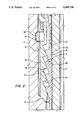
- FIG. 5 is a partial quarter sectional view illustrating an alternate embodiment of a portion of the mandrel hanger assembly of FIG. 1.
- wellhead housing 11 will be located at a surface platform, which will normally be supported on legs on the sea floor.
- Wellhead housing il has an axial bore 13 with an upward facing conical shoulder 15.
- a mandrel 17 has a lower end (not shown) that secures to an upper end of a string of casing.
- the string of casing will extend down to the sea floor and into the well.
- the string of casing will latch in a mudline hanger (not shown) in a subsea housing in a conventional manner.
- Mandrel 17 is a tubular member having a plurality of wickers 19 on its exterior. Wickers 19 are small circumferentially extending grooves. Wickers 19 are not threads, rather are located in planes perpendicular to the axis of mandrel 17. Wickers 19 are triangular in configuration, as illustrated in FIG. 3.
- each wicker 19 is contained in planes that incline relative to the axis of mandrel 17 at the same angular degree.
- Mandrel 17 also has a set of threads 21 on its upper end, as shown in FIG. 1b.
- Collet 23 will slide downward over mandrel 17.
- Collet 23, as illustrated also in FIG. 3, is a tubular member having a plurality of wickers 25 in its interior. Wickers 25 are identical to wickers 19.
- Collet 23 has expansion means for allowing it to expand and contract to allow wickers 25 to ratchet over wickers 19 when mandrel 17 moves upward relative to collet 23.
- the expansion means comprises alternating upper slots 27 and lower slots 29.
- the upper slots 27 extend downward from the upper edge of collet 23.
- the lower slots 29 extend upward from the lower edge of collet 23. This results in a generally serpentine configuration to the body of collet 23.
- Collet 23 has a plurality of load flanks 31 on its exterior.
- Load flanks 31 are large circumferential grooves relative to wickers 25. The pitch or distance between each load flank 31 will be many times as great as the pitch between the wickers 25.
- Each load flank 31 is formed helically, rather than parallel as wickers 25.
- Each load flank 31 is conical and inclines relative to the axis of mandrel 17 at approximately a 20 degree angle.
- Each load flank 31 faces downward and outward and is separated from adjacent load flanks 31 by upper flanks 32.
- Upper flanks 32 face upward and outward and incline relative to the axis of mandrel 17 at an angle of about 10 degrees.
- a plurality of fishing neck lugs 33 are located on the upper end of collet 23.
- Fishing neck lugs 33 are hooks, spaced circumferentially apart from each other, resulting in vertical slots 34 between each lug 33. Lugs 33 enable collet 23 to be released if necessary.
- collet 23 locates within a load ring 35.
- Load ring 35 is a solid ring, having no vertical slots, and being inexpansable.
- Load ring 35 has a lower end that lands on wellhead housing shoulder 15.
- Load ring 35 has a plurality of load flanks 37 in its interior. Load flanks 37 mate with load flanks 31. Each load flank 37 faces upward and inward.
- Load flanks 37 are identical in configuration to load flanks 31.
- Each load flank 37 is separated from adjacent load flanks 37 by a downward facing lower flank 38.
- Lower flank 38 is parallel to upper flank 32.
- a split retainer ring 39 is carried by load ring 35.
- Retainer ring 39 serves as means for locking load ring 35 into wellhead housing.
- Retainer ring 39 is biased outward for snapping into a recess 41 formed in bore 13 above shoulder 15.
- Running tool 43 secures to mandrel 17.
- Running tool 43 has an inner barrel 45 which has threads 47 on its lower end. Threads 47 engage threads 21 on the upper end of mandrel 17.
- Running tool 43 has an outer barrel 49 that extends slidingly over inner barrel 45.
- Outer barrel 49 has a lower end 51 that will bear against the upper end of load ring 35.
- Lower end 51 has a plurality of hooks 53 separated by vertical slots, each hook 53 extending inward from the lower end 51.
- the slots (not shown) in the lower end 51 enable the hooks 53 to pass through the slots 34 between the lugs 33 on collet 23.
- the width of each hook 53 is slightly less than the width of each slot 34, so as to allow the hooks 53 to be pulled upward with outer barrel 49 without engaging lugs 33.
- a pair of O-ring seals 55, 57 are located on inner barrel 45. Seals 55, 57 seal against the bore of outer barrel 49. As shown in FIG. 1a, a hydraulic chamber 59 is provided between the seals 55, 57. A hydraulic passage 61 leads through outer barrel 49 to communicate hydraulic fluid from a conduit 63 to chamber 59. Supplying hydraulic fluid to chamber 59 will cause outer barrel 49 to move downward relative to inner barrel 45.
- a subsea housing In operation, a subsea housing will be located at the sea floor. After the well has been drilled to a selected depth, casing will be lowered into and cemented in the well. The casing in the well will be suspended at a conventional mudline hanger at the subsea wellhead.
- tieback casing string from the mudline hanger t the wellhead housing 11 located on a production platform.
- the tieback string of casing will have a mudline hanger latch for latching into the mudline hanger at the subsea wellhead housing.
- Mandrel 17 will be secured to the upper end of the string of tieback casing.
- Collet 23 will be located in load ring 35 and placed on the mandrel 17 at the upper end of mandrel 17.
- the inner barrel 45 of running tool 43 will be secured to mandrel 17.
- the operator will pull upward by lifting the running tool 43 with a lifting means at the platform, such as drilling rig blocks.
- a lifting means at the platform, such as drilling rig blocks.
- the operator will supply hydraulic fluid pressure to chamber 59, while maintaining the upward force on mandrel 17.
- This causes outer barrel 49 to begin moving downward relative to inner barrel 45, which is held stationary.
- the lower end 51 of outer barrel 49 pushes down on the load ring 35, causing collet 23 to move downward.
- wickers 25 will ratchet on wickers 19.
- the load ring 35 lands on shoulder 15 of wellhead housing 11, and retainer ring 39 snaps into recess 41.
- the load flanks 31 will slide upward and downward on the load flanks 37.
- seal 65 may be installed on top of collet 23.
- Seal 65 may be of various types, such as one shown in U.S. Pat. No. 4,665,979, Carl F. Boehm, Jr., issued May 19, 1987. Seal 65 seals against mandrel wickers 19.
- the operator may utilize the running tool 43. Once in position as shown in FIG. 1b, and with the seal 65 removed, the operator rotates the outer barrel 49 slightly so that hooks 53 locate below and engage lugs 33. The operator then screws the running tool inner barrel 45 onto the mandrel threads 21. The operator will then pull the running tool inner barrel 45 upward with the drilling rig blocks to a tension sufficient to remove the compressive load passing through the collet 23 and load ring 35 to the shoulder 15.
- FIG. 5 illustrates an alternate embodiment, with mandrel 17' and collet 35' being the same as in the first embodiment.
- the load ring 35' differs in that it employs a different retainer ring 39'.
- Split retainer ring 39' has a sharp upward facing shoulder for engaging recess 41 (FIG. 4).
- Recess 41 will be configured with a sharper downward facing shoulder than shown in the first embodiment.
- Retainer ring 39' snaps into recess 41 when the load ring 35' moves downward adjacent recess 41.
- a cam ring 67 locates above the retainer ring 39' and engages a tapered surface on retainer ring 39'.
- Cam ring 67 is pinned to retainer ring 39' by a shear pin 69.
- Shear pin 69 does not shear during running of load ring 35', and cam ring 67 remains fixed to retainer ring 39' in a position to avoid interference with the outward movement of retainer ring 39' into recess 41.
Landscapes
- Life Sciences & Earth Sciences (AREA)
- Engineering & Computer Science (AREA)
- Geology (AREA)
- Mining & Mineral Resources (AREA)
- Physics & Mathematics (AREA)
- Environmental & Geological Engineering (AREA)
- Fluid Mechanics (AREA)
- General Life Sciences & Earth Sciences (AREA)
- Geochemistry & Mineralogy (AREA)
- Earth Drilling (AREA)
Abstract
Description
Claims (10)
Priority Applications (2)
| Application Number | Priority Date | Filing Date | Title |
|---|---|---|---|
| US07/927,025 US5255746A (en) | 1992-08-06 | 1992-08-06 | Adjustable mandrel hanger assembly |
| GB9316025A GB2269414B (en) | 1992-08-06 | 1993-08-03 | Adjustable mandrel hanger assembly |
Applications Claiming Priority (1)
| Application Number | Priority Date | Filing Date | Title |
|---|---|---|---|
| US07/927,025 US5255746A (en) | 1992-08-06 | 1992-08-06 | Adjustable mandrel hanger assembly |
Publications (1)
| Publication Number | Publication Date |
|---|---|
| US5255746A true US5255746A (en) | 1993-10-26 |
Family
ID=25454052
Family Applications (1)
| Application Number | Title | Priority Date | Filing Date |
|---|---|---|---|
| US07/927,025 Expired - Lifetime US5255746A (en) | 1992-08-06 | 1992-08-06 | Adjustable mandrel hanger assembly |
Country Status (2)
| Country | Link |
|---|---|
| US (1) | US5255746A (en) |
| GB (1) | GB2269414B (en) |
Cited By (29)
| Publication number | Priority date | Publication date | Assignee | Title |
|---|---|---|---|---|
| US5439061A (en) * | 1994-08-03 | 1995-08-08 | Abb Vetco Gray Inc. | Adjustable surface well head casing hanger |
| US5450904A (en) * | 1994-08-23 | 1995-09-19 | Abb Vetco Gray Inc. | Adjustable tieback sub |
| US5607019A (en) * | 1995-04-10 | 1997-03-04 | Abb Vetco Gray Inc. | Adjustable mandrel hanger for a jackup drilling rig |
| US5638903A (en) * | 1995-04-10 | 1997-06-17 | Abb Vetco Gray Inc. | Adjustable mandrel hanger system |
| US5655606A (en) * | 1996-01-29 | 1997-08-12 | Abb Vetco Gray Inc. | Running tool for installing a wellhead load shoulder |
| US5671812A (en) * | 1995-05-25 | 1997-09-30 | Abb Vetco Gray Inc. | Hydraulic pressure assisted casing tensioning system |
| US5839512A (en) * | 1995-12-14 | 1998-11-24 | Fmc Corporation | Adjustable casing hanger with contractible load shoulder and metal sealing ratch latch adjustment sub |
| US5873678A (en) * | 1996-12-23 | 1999-02-23 | Continental Emsco Company | Tension adjustment mechanism employing stepped or serrated ramps for adjusting tension of a tendon from a floating marine platform |
| EP0898048A3 (en) * | 1997-08-20 | 1999-08-18 | Halliburton Energy Services, Inc. | Slip for use in a subterranean well |
| GB2351104A (en) * | 2000-07-13 | 2000-12-20 | Fmc Corp | Tubing hanger lockdown mechanism |
| US6234252B1 (en) | 1998-03-26 | 2001-05-22 | Abb Vetco Gray Inc. | External tieback connector and method for tying back riser to subsea wellhead |
| US6516887B2 (en) * | 2001-01-26 | 2003-02-11 | Cooper Cameron Corporation | Method and apparatus for tensioning tubular members |
| US6540024B2 (en) * | 2000-05-26 | 2003-04-01 | Abb Vetco Gray Inc. | Small diameter external production riser tieback connector |
| US20040069493A1 (en) * | 2001-05-24 | 2004-04-15 | Borak Eugene A. | One-trip wellhead installation systems and methods |
| US20040188087A1 (en) * | 2002-09-30 | 2004-09-30 | Deberry Blake T. | Adjustable hanger system and method |
| US20050006107A1 (en) * | 2003-07-07 | 2005-01-13 | Cooper Cameron Corporation | One trip string tensioning and hanger securing method |
| US20080230233A1 (en) * | 2007-03-19 | 2008-09-25 | Fay Peter J | Coupler retained liner hanger mechanism and methods of setting a hanger inside a wellbore |
| US20080308278A1 (en) * | 2007-06-18 | 2008-12-18 | Vetco Gray Inc. | Adjustable threaded hanger and running tool |
| US20090200797A1 (en) * | 2006-10-17 | 2009-08-13 | Car-Ber Investments Inc. | Pipe fitting and pipe coupling assembly employing such fitting |
| US20100018716A1 (en) * | 2008-07-28 | 2010-01-28 | Vetco Gray Inc. | Adjustable Hanger for Inner Production Riser |
| US20100276162A1 (en) * | 2008-11-11 | 2010-11-04 | Vetco Gray Inc. | Metal Annulus Seal |
| US20100307767A1 (en) * | 2009-06-03 | 2010-12-09 | Fay Peter J | Coupler retained liner hanger mechanism with moveable cover and methods of setting a hanger inside a wellbore |
| US20110240307A1 (en) * | 2008-03-28 | 2011-10-06 | Cameron International Corporation | Wellhead Hanger Shoulder |
| US20130248196A1 (en) * | 2012-03-23 | 2013-09-26 | Vetco Gray Inc. | High-capacity single-trip lockdown bushing and a method to operate the same |
| US8863847B2 (en) * | 2010-12-13 | 2014-10-21 | Cameron International Corporation | Adjustable riser suspension and sealing system |
| US10081986B2 (en) * | 2016-01-07 | 2018-09-25 | Ensco International Incorporated | Subsea casing tieback |
| WO2019018496A1 (en) * | 2017-07-18 | 2019-01-24 | Ge Oil Gas Pressure Control Lp | Slip hanger assembly |
| WO2019209814A1 (en) * | 2018-04-24 | 2019-10-31 | Dril-Quip, Inc. | Releasable ratchet latch connector |
| US11713639B2 (en) * | 2020-01-21 | 2023-08-01 | Baker Hughes Oilfield Operations Llc | Pressure energized seal with groove profile |
Families Citing this family (1)
| Publication number | Priority date | Publication date | Assignee | Title |
|---|---|---|---|---|
| US8662185B2 (en) | 2010-12-27 | 2014-03-04 | Vetco Gray Inc. | Active casing hanger hook mechanism |
Citations (6)
| Publication number | Priority date | Publication date | Assignee | Title |
|---|---|---|---|---|
| US4456070A (en) * | 1982-07-26 | 1984-06-26 | Hughes Tool Company | Tieback connection method and apparatus |
| US4903992A (en) * | 1989-04-14 | 1990-02-27 | Vetco Gray Inc. | Locking ring for oil well tool |
| US4909546A (en) * | 1987-10-27 | 1990-03-20 | Vetco Gray Inc. | Tension lock multibowl wellhead |
| US4919454A (en) * | 1989-02-14 | 1990-04-24 | Vetco Gray Inc. | Tieback connector with protective landing sleeve |
| US4949786A (en) * | 1989-04-07 | 1990-08-21 | Vecto Gray Inc. | Emergency casing hanger |
| US5002131A (en) * | 1990-01-18 | 1991-03-26 | Vetco Gray Inc. | Casing tensioning mechanism for a casing hanger |
Family Cites Families (1)
| Publication number | Priority date | Publication date | Assignee | Title |
|---|---|---|---|---|
| US5176218A (en) * | 1991-05-31 | 1993-01-05 | Fmc Corporation | Adjustable mandrel well casing hanger |
-
1992
- 1992-08-06 US US07/927,025 patent/US5255746A/en not_active Expired - Lifetime
-
1993
- 1993-08-03 GB GB9316025A patent/GB2269414B/en not_active Expired - Fee Related
Patent Citations (6)
| Publication number | Priority date | Publication date | Assignee | Title |
|---|---|---|---|---|
| US4456070A (en) * | 1982-07-26 | 1984-06-26 | Hughes Tool Company | Tieback connection method and apparatus |
| US4909546A (en) * | 1987-10-27 | 1990-03-20 | Vetco Gray Inc. | Tension lock multibowl wellhead |
| US4919454A (en) * | 1989-02-14 | 1990-04-24 | Vetco Gray Inc. | Tieback connector with protective landing sleeve |
| US4949786A (en) * | 1989-04-07 | 1990-08-21 | Vecto Gray Inc. | Emergency casing hanger |
| US4903992A (en) * | 1989-04-14 | 1990-02-27 | Vetco Gray Inc. | Locking ring for oil well tool |
| US5002131A (en) * | 1990-01-18 | 1991-03-26 | Vetco Gray Inc. | Casing tensioning mechanism for a casing hanger |
Cited By (55)
| Publication number | Priority date | Publication date | Assignee | Title |
|---|---|---|---|---|
| US5439061A (en) * | 1994-08-03 | 1995-08-08 | Abb Vetco Gray Inc. | Adjustable surface well head casing hanger |
| US5450904A (en) * | 1994-08-23 | 1995-09-19 | Abb Vetco Gray Inc. | Adjustable tieback sub |
| US5607019A (en) * | 1995-04-10 | 1997-03-04 | Abb Vetco Gray Inc. | Adjustable mandrel hanger for a jackup drilling rig |
| US5638903A (en) * | 1995-04-10 | 1997-06-17 | Abb Vetco Gray Inc. | Adjustable mandrel hanger system |
| US5671812A (en) * | 1995-05-25 | 1997-09-30 | Abb Vetco Gray Inc. | Hydraulic pressure assisted casing tensioning system |
| US5839512A (en) * | 1995-12-14 | 1998-11-24 | Fmc Corporation | Adjustable casing hanger with contractible load shoulder and metal sealing ratch latch adjustment sub |
| US5655606A (en) * | 1996-01-29 | 1997-08-12 | Abb Vetco Gray Inc. | Running tool for installing a wellhead load shoulder |
| US5873678A (en) * | 1996-12-23 | 1999-02-23 | Continental Emsco Company | Tension adjustment mechanism employing stepped or serrated ramps for adjusting tension of a tendon from a floating marine platform |
| EP0898048A3 (en) * | 1997-08-20 | 1999-08-18 | Halliburton Energy Services, Inc. | Slip for use in a subterranean well |
| US6293343B1 (en) | 1998-03-26 | 2001-09-25 | Abb Vetco Gray, Inc. | External tieback connector and method for tying back riser to subsea wellhead |
| US6234252B1 (en) | 1998-03-26 | 2001-05-22 | Abb Vetco Gray Inc. | External tieback connector and method for tying back riser to subsea wellhead |
| US6540024B2 (en) * | 2000-05-26 | 2003-04-01 | Abb Vetco Gray Inc. | Small diameter external production riser tieback connector |
| SG92809A1 (en) * | 2000-07-13 | 2002-11-19 | Fmc Corp | Tubing hanger lockdown mechanism |
| GB2351104B (en) * | 2000-07-13 | 2001-05-09 | Fmc Corp | Tubing hanger lockdown mechanism |
| US6516875B2 (en) | 2000-07-13 | 2003-02-11 | Fmc Technologies, Inc. | Tubing hanger lockdown mechanism |
| GB2351104A (en) * | 2000-07-13 | 2000-12-20 | Fmc Corp | Tubing hanger lockdown mechanism |
| US6516887B2 (en) * | 2001-01-26 | 2003-02-11 | Cooper Cameron Corporation | Method and apparatus for tensioning tubular members |
| US20040069493A1 (en) * | 2001-05-24 | 2004-04-15 | Borak Eugene A. | One-trip wellhead installation systems and methods |
| US6918446B2 (en) | 2001-05-24 | 2005-07-19 | Vetco Gray Inc. | One-trip wellhead installation systems and methods |
| US20040188087A1 (en) * | 2002-09-30 | 2004-09-30 | Deberry Blake T. | Adjustable hanger system and method |
| US7040412B2 (en) * | 2002-09-30 | 2006-05-09 | Dril-Quip, Inc. | Adjustable hanger system and method |
| US20050006107A1 (en) * | 2003-07-07 | 2005-01-13 | Cooper Cameron Corporation | One trip string tensioning and hanger securing method |
| US7350583B2 (en) | 2003-07-07 | 2008-04-01 | Cameron International Corporation | One trip string tensioning and hanger securing method |
| US20090200797A1 (en) * | 2006-10-17 | 2009-08-13 | Car-Ber Investments Inc. | Pipe fitting and pipe coupling assembly employing such fitting |
| US20090159268A1 (en) * | 2007-03-19 | 2009-06-25 | Fay Peter J | Coupler retained liner hanger mechanism and methods of setting a hanger inside a wellbore |
| US7537060B2 (en) * | 2007-03-19 | 2009-05-26 | Baker Hughes Incorporated | Coupler retained liner hanger mechanism and methods of setting a hanger inside a wellbore |
| US20080230233A1 (en) * | 2007-03-19 | 2008-09-25 | Fay Peter J | Coupler retained liner hanger mechanism and methods of setting a hanger inside a wellbore |
| US7604061B2 (en) * | 2007-03-19 | 2009-10-20 | Baker Hughes Incorporated | Coupler retained liner hanger mechanism and methods of setting a hanger inside a wellbore |
| US8006764B2 (en) | 2007-06-18 | 2011-08-30 | Vetco Gray Inc. | Adjustable threaded hanger |
| US20080308278A1 (en) * | 2007-06-18 | 2008-12-18 | Vetco Gray Inc. | Adjustable threaded hanger and running tool |
| GB2450408B (en) * | 2007-06-18 | 2011-10-05 | Vetco Gray Inc | Adjustable threaded hanger and running tool |
| GB2450408A (en) * | 2007-06-18 | 2008-12-24 | Vetco Gray Inc | A casing hanger assembly allowing for the application of tension |
| US20110240307A1 (en) * | 2008-03-28 | 2011-10-06 | Cameron International Corporation | Wellhead Hanger Shoulder |
| US8851182B2 (en) * | 2008-03-28 | 2014-10-07 | Cameron International Corporation | Wellhead hanger shoulder |
| WO2010014382A3 (en) * | 2008-07-28 | 2010-04-01 | Vetco Gray, Inc. | Adjustable hanger for inner production riser |
| GB2476735B (en) * | 2008-07-28 | 2013-06-26 | Vetco Gray Inc | Adjustable hanger for inner production riser |
| US8261837B2 (en) | 2008-07-28 | 2012-09-11 | Vetco Gray Inc. | Adjustable hanger for inner production riser |
| US20100018716A1 (en) * | 2008-07-28 | 2010-01-28 | Vetco Gray Inc. | Adjustable Hanger for Inner Production Riser |
| US20100276162A1 (en) * | 2008-11-11 | 2010-11-04 | Vetco Gray Inc. | Metal Annulus Seal |
| US8205670B2 (en) * | 2008-11-11 | 2012-06-26 | Vetco Gray Inc. | Metal annulus seal |
| US8002044B2 (en) | 2009-06-03 | 2011-08-23 | Baker Hughes Incorporated | Coupler retained liner hanger mechanism with moveable cover and methods of setting a hanger inside a wellbore |
| US20100307767A1 (en) * | 2009-06-03 | 2010-12-09 | Fay Peter J | Coupler retained liner hanger mechanism with moveable cover and methods of setting a hanger inside a wellbore |
| US8863847B2 (en) * | 2010-12-13 | 2014-10-21 | Cameron International Corporation | Adjustable riser suspension and sealing system |
| US9347280B2 (en) | 2010-12-13 | 2016-05-24 | Cameron International Corporation | Adjustable riser suspension and sealing system |
| US20130248196A1 (en) * | 2012-03-23 | 2013-09-26 | Vetco Gray Inc. | High-capacity single-trip lockdown bushing and a method to operate the same |
| US9376881B2 (en) * | 2012-03-23 | 2016-06-28 | Vetco Gray Inc. | High-capacity single-trip lockdown bushing and a method to operate the same |
| US10081986B2 (en) * | 2016-01-07 | 2018-09-25 | Ensco International Incorporated | Subsea casing tieback |
| WO2019018496A1 (en) * | 2017-07-18 | 2019-01-24 | Ge Oil Gas Pressure Control Lp | Slip hanger assembly |
| GB2579496A (en) * | 2017-07-18 | 2020-06-24 | Ge Oil & Gas Pressure Control Lp | Slip hanger assembly |
| GB2579496B (en) * | 2017-07-18 | 2022-01-12 | Ge Oil & Gas Pressure Control Lp | Slip hanger assembly |
| WO2019209814A1 (en) * | 2018-04-24 | 2019-10-31 | Dril-Quip, Inc. | Releasable ratchet latch connector |
| GB2586386A (en) * | 2018-04-24 | 2021-02-17 | Dril Quip Inc | Releasable ratchet latch connector |
| GB2586386B (en) * | 2018-04-24 | 2022-06-08 | Dril Quip Inc | Releasable ratchet latch connector |
| US11371294B2 (en) | 2018-04-24 | 2022-06-28 | Dril-Quip, Inc. | Releasable ratchet latch connector |
| US11713639B2 (en) * | 2020-01-21 | 2023-08-01 | Baker Hughes Oilfield Operations Llc | Pressure energized seal with groove profile |
Also Published As
| Publication number | Publication date |
|---|---|
| GB2269414A (en) | 1994-02-09 |
| GB9316025D0 (en) | 1993-09-15 |
| GB2269414B (en) | 1995-12-06 |
Similar Documents
| Publication | Publication Date | Title |
|---|---|---|
| US5255746A (en) | Adjustable mandrel hanger assembly | |
| US5944111A (en) | Internal riser tensioning system | |
| US5607019A (en) | Adjustable mandrel hanger for a jackup drilling rig | |
| US5671812A (en) | Hydraulic pressure assisted casing tensioning system | |
| US4469172A (en) | Self-energizing locking mechanism | |
| US4641708A (en) | Casing hanger locking device | |
| US5638903A (en) | Adjustable mandrel hanger system | |
| US7896081B2 (en) | Internal tieback for subsea well | |
| US3543847A (en) | Casing hanger apparatus | |
| US5163514A (en) | Blowout preventer isolation test tool | |
| US3721292A (en) | Marine riser liner apparatus and methods of installing such apparatus | |
| US5002131A (en) | Casing tensioning mechanism for a casing hanger | |
| US5311947A (en) | Preselected casing tensioning system | |
| US6536527B2 (en) | Connection system for catenary riser | |
| US5653289A (en) | Adjustable jackup drilling system hanger | |
| US4928769A (en) | Casing hanger running tool using string weight | |
| US5450904A (en) | Adjustable tieback sub | |
| US5279369A (en) | Tieback receptacle with upward and downward facing funnel sections | |
| US7234528B2 (en) | Multi-purpose sleeve for tieback connector | |
| US4171018A (en) | Tubing hanger assembly and method of landing and locking | |
| US6003602A (en) | Tree bore protector | |
| US3521909A (en) | Remote underwater wellhead connector | |
| US5368335A (en) | Contingency tieback adapter | |
| US5222560A (en) | Full bore internal tieback system and method | |
| US5090737A (en) | Downhole energizable seal for telescoping joints |
Legal Events
| Date | Code | Title | Description |
|---|---|---|---|
| AS | Assignment |
Owner name: ABB VETCO GRAY INC., A CORPORATION OF DELAWARE, TE Free format text: ASSIGNMENT OF ASSIGNORS INTEREST.;ASSIGNOR:BRIDGES, CHARLES D.;REEL/FRAME:006235/0256 Effective date: 19920724 |
|
| STCF | Information on status: patent grant |
Free format text: PATENTED CASE |
|
| CC | Certificate of correction | ||
| FEPP | Fee payment procedure |
Free format text: PAYOR NUMBER ASSIGNED (ORIGINAL EVENT CODE: ASPN); ENTITY STATUS OF PATENT OWNER: LARGE ENTITY |
|
| FPAY | Fee payment |
Year of fee payment: 4 |
|
| FEPP | Fee payment procedure |
Free format text: PAYER NUMBER DE-ASSIGNED (ORIGINAL EVENT CODE: RMPN); ENTITY STATUS OF PATENT OWNER: LARGE ENTITY Free format text: PAYOR NUMBER ASSIGNED (ORIGINAL EVENT CODE: ASPN); ENTITY STATUS OF PATENT OWNER: LARGE ENTITY |
|
| REMI | Maintenance fee reminder mailed | ||
| FPAY | Fee payment |
Year of fee payment: 8 |
|
| SULP | Surcharge for late payment |
Year of fee payment: 7 |
|
| AS | Assignment |
Owner name: J.P. MORGAN EUROPE LIMITED, AS SECURITY AGENT, UNI Free format text: SECURITY AGREEMENT;ASSIGNOR:ABB VETCO GRAY INC.;REEL/FRAME:015215/0851 Effective date: 20040712 |
|
| FPAY | Fee payment |
Year of fee payment: 12 |