US5176206A - Laminate type heat exchanger - Google Patents
Laminate type heat exchanger Download PDFInfo
- Publication number
- US5176206A US5176206A US07/696,687 US69668791A US5176206A US 5176206 A US5176206 A US 5176206A US 69668791 A US69668791 A US 69668791A US 5176206 A US5176206 A US 5176206A
- Authority
- US
- United States
- Prior art keywords
- tubular elements
- stamped
- plates
- recess
- laminate structure
- Prior art date
- Legal status (The legal status is an assumption and is not a legal conclusion. Google has not performed a legal analysis and makes no representation as to the accuracy of the status listed.)
- Expired - Fee Related
Links
Images


Classifications
-
- F—MECHANICAL ENGINEERING; LIGHTING; HEATING; WEAPONS; BLASTING
- F28—HEAT EXCHANGE IN GENERAL
- F28D—HEAT-EXCHANGE APPARATUS, NOT PROVIDED FOR IN ANOTHER SUBCLASS, IN WHICH THE HEAT-EXCHANGE MEDIA DO NOT COME INTO DIRECT CONTACT
- F28D1/00—Heat-exchange apparatus having stationary conduit assemblies for one heat-exchange medium only, the media being in contact with different sides of the conduit wall, in which the other heat-exchange medium is a large body of fluid, e.g. domestic or motor car radiators
- F28D1/02—Heat-exchange apparatus having stationary conduit assemblies for one heat-exchange medium only, the media being in contact with different sides of the conduit wall, in which the other heat-exchange medium is a large body of fluid, e.g. domestic or motor car radiators with heat-exchange conduits immersed in the body of fluid
- F28D1/03—Heat-exchange apparatus having stationary conduit assemblies for one heat-exchange medium only, the media being in contact with different sides of the conduit wall, in which the other heat-exchange medium is a large body of fluid, e.g. domestic or motor car radiators with heat-exchange conduits immersed in the body of fluid with plate-like or laminated conduits
- F28D1/0308—Heat-exchange apparatus having stationary conduit assemblies for one heat-exchange medium only, the media being in contact with different sides of the conduit wall, in which the other heat-exchange medium is a large body of fluid, e.g. domestic or motor car radiators with heat-exchange conduits immersed in the body of fluid with plate-like or laminated conduits the conduits being formed by paired plates touching each other
- F28D1/0325—Heat-exchange apparatus having stationary conduit assemblies for one heat-exchange medium only, the media being in contact with different sides of the conduit wall, in which the other heat-exchange medium is a large body of fluid, e.g. domestic or motor car radiators with heat-exchange conduits immersed in the body of fluid with plate-like or laminated conduits the conduits being formed by paired plates touching each other the plates having lateral openings therein for circulation of the heat-exchange medium from one conduit to another
- F28D1/0333—Heat-exchange apparatus having stationary conduit assemblies for one heat-exchange medium only, the media being in contact with different sides of the conduit wall, in which the other heat-exchange medium is a large body of fluid, e.g. domestic or motor car radiators with heat-exchange conduits immersed in the body of fluid with plate-like or laminated conduits the conduits being formed by paired plates touching each other the plates having lateral openings therein for circulation of the heat-exchange medium from one conduit to another the plates having integrated connecting members
- F28D1/0341—Heat-exchange apparatus having stationary conduit assemblies for one heat-exchange medium only, the media being in contact with different sides of the conduit wall, in which the other heat-exchange medium is a large body of fluid, e.g. domestic or motor car radiators with heat-exchange conduits immersed in the body of fluid with plate-like or laminated conduits the conduits being formed by paired plates touching each other the plates having lateral openings therein for circulation of the heat-exchange medium from one conduit to another the plates having integrated connecting members with U-flow or serpentine-flow inside the conduits
-
- F—MECHANICAL ENGINEERING; LIGHTING; HEATING; WEAPONS; BLASTING
- F28—HEAT EXCHANGE IN GENERAL
- F28F—DETAILS OF HEAT-EXCHANGE AND HEAT-TRANSFER APPARATUS, OF GENERAL APPLICATION
- F28F17/00—Removing ice or water from heat-exchange apparatus
- F28F17/005—Means for draining condensates from heat exchangers, e.g. from evaporators
-
- F—MECHANICAL ENGINEERING; LIGHTING; HEATING; WEAPONS; BLASTING
- F28—HEAT EXCHANGE IN GENERAL
- F28F—DETAILS OF HEAT-EXCHANGE AND HEAT-TRANSFER APPARATUS, OF GENERAL APPLICATION
- F28F3/00—Plate-like or laminated elements; Assemblies of plate-like or laminated elements
- F28F3/02—Elements or assemblies thereof with means for increasing heat-transfer area, e.g. with fins, with recesses, with corrugations
- F28F3/04—Elements or assemblies thereof with means for increasing heat-transfer area, e.g. with fins, with recesses, with corrugations the means being integral with the element
Definitions
- This invention relates to a laminate type heat exchanger, and more particularly to a laminate type heat exchanger for use as an evaporator of an automotive air conditioning system or the like.
- a conventional laminate type heat exchanger of this type comprises a plurality of tubular elements each formed of a pair of generally flat stamped plates joined together in an abutting manner along angled outer peripheral edges thereof, the tubular elements each having tanks at one end thereof, a plurality of fins, typically corrugated, the tubular elements and the fins being superposed one upon another in an alternate manner to form a laminate structure, and a pair of end plates attached to outermost ones of the tubular elements at opposite ends of the laminate structure, as disclosed in Japanese Provisional Patent Publication (Kokai) No. 63-153397.
- This laminate type heat exchanger has a tank section at one end thereof, and each end plate and its associated stamped plate are joined together at one end of the tubular element remote from the tank section in a manner as shown in FIG. 1.
- the outermost stamped plate 100 has an inner side surface thereof formed with a generally flat refrigerant passage-forming recess 102 bordered by its angled outer peripheral edge 101.
- a multiplicity of projections or beads 103 are formed integrally over the surface of the refrigerant passage-forming recess 102.
- the end plate 110 which is attached to each outermost stamped plate 100 is so shaped or stamped as to have a joining peripheral portion (joining portion) 111 abutting against an outer side surface 102a of the stamped plate 100 at a location corresponding to at least two recessed portions of the recess 102, and a swelled main portion 112 defining therein a space accommodating a corrugated fin 120 together with the outer side surface 102a of the stamped plate 100.
- the joining portion 111 of the end plate 110 is brazed to the outer side surface 102a of the stamped plate 100.
- the joining portion 111 of the end plate 110 abuts against and brazed to the outer side surface 102a of the stamped plate 100 at a location corresponding to at least two recessed portions of the recess 102, as noted above.
- an enclosed space 130 is defined in the joined portions of the end plate 110 and the stamped plate 100.
- the joining portion 111 of the end plate 110 and the outer side surface 102a of the stamped plate 100 are joined together in a face-to-face manner by brazing so that usually gaps such as pinholes can be formed in the brazed surfaces.
- the present invention provides a laminate type heat exchanger including a plurality of tubular elements each formed of a pair of generally flat stamped plates joined together in an abutting manner, the tubular elements each having a tank section at one end thereof, a plurality of fins, the tubular elements and the fins being superposed one upon another in an alternate manner to form a laminate structure, and a pair of end plates attached to outermost ones of the tubular elements at opposite ends of the laminate structure, the end plates each having a joining section joined to an associated one of the outermost ones of the tubular elements, a swelled main portion, and a fin accommodated within the swelled main portion, the stamped plates each having one side surface thereof formed with a recess forming a thermal medium passage in cooperation with a recess formed in one side surface of an associated one of the stamped plates, the recess having a surface thereof formed with a multiplicity of projections arranged in a plurality of rows, outermost ones of the stamped plates at the opposite ends
- the laminate type heat exchanger according to the invention is characterized in that the joining section of each of the end plates includes a joining portion abutting against a portion of the another side surface of an associated one of the outermost ones of the stamped plates, said portion of the another side surface corresponding in location to the aforesaid portion of the recess, the joining portion being shaped and sized such that the at least one row of the depressions of the associated one of the outermost ones of the stamped plates communicates with one of the interior of the swelled main portion of the each of the end plates and the outside of the heat exchanger.
- FIG. 1 is a fragmentary sectional view of joined portions of an end plate and its associated stamped plate at one end of a conventional laminate type heat exchanger remote from a tank section thereof;
- FIG. 2 is a front view of a laminate type heat exchanger according to a first embodiment of the invention
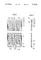
- FIG. 3 is a front view of an outermost stamped plate at an end of the heat exchanger
- FIG. 4 is a sectional view taken along line IV--IV in FIG. 3;
- FIG. 5 is a fragmentary view of joined portions of the end plate and the stamped plate at ends thereof remote from the tank section, as viewed from a side indicated by the arrow A in FIG. 2;
- FIG. 6 is a fragmentary sectional view taken along line VI--VI in FIG. 5;
- FIG. 7 is a fragmentary side view similar to FIG. 5, showing a second embodiment of the invention.
- FIG. 8 is a sectional view taken along line VIII--VIII in FIG. 7;
- FIG. 9 is a fragmentary side view similar to FIG. 5, showing a third embodiment of the invention.
- FIG. 10 is a sectional view taken along line X--X in FIG. 9.
- the laminate heat exchangers according to the invention are embodied as evaporators for use in automotive air conditioning systems.
- FIG. 2 there is illustrated a laminate type heat exchanger according to a first embodiment of the invention.
- reference numeral 1 designates the heat exchanger having a casing 2.
- the heat exchanger 1 comprises a plurality of tubular elements 3, and a plurality of corrugated fins 4, the tubular elements 3 and the fins 4 being superposed one upon another in an alternate manner to form a laminate structure, and a pair of end plates 5, 5 attached to outermost ones 3A, 3A of the tubular elements at opposite ends of the laminate structure.
- the illustrated heat exchanger 1 comprises 16 pairs of tubular elements and corrugated fins.
- Each tubular element 3 comprises a pair of generally flat stamped plates 3a, 3a joined together in an abutting manner.
- the joined stamped plates 3a, 3a cooperatively define a refrigerant passage, not shown, therebetween, a first tank 7a arranged on an upstream side in the direction of flow of heat-exchanging air flowing through the refrigerant passage, and a second tank 7b arranged on a downstream side in the same direction.
- the refrigerant passage has a U-shaped configuration divided by partitions formed on the stamped plates by partition-forming projections having the same configuration as a partition-forming projection 24 formed on an outermost stamped plate 3b at an end of the heat exchanger, appearing in FIG.
- a first tank section 7 1 is formed by the first tanks 7a of the stamped plates 100, while a second tank section 7 2 is formed by the second tanks of the stamped plates 100.
- the first and second tank sections 7 1 , 7 2 will be hereinafter generically called a tank section 7.
- First tanks 7a forming the first tank section 7 1 other than those at a central portion of the laminate structure are communicated with each other by means of communication holes, not shown, while all the second tanks 7b forming the second tank section 7 2 are communicated with each other by means of communication holes, not shown, over the whole length of the laminate structure.
- a refrigerant-inlet pipe 8 is connected to the laminate structure at a left side with respect to a central portion of the inlet side tank section 7 1 , while a refrigerant-outlet pipe 9 is connected to the laminate structure at a right side with respect to a central portion of the outlet side tank section 7 2 .
- Each end plate 5 is so shaped or stamped as to have a joining portion 5a at an end thereof remote from the tank section 7, a joining portion 5b at the other end provided with the tank section 7, and a swelled main portion 5c accommodating a corrugated fin 4, the joining portions 5a, 5b being brazed to the respective associated stamped plates at the opposite ends of the laminate structure.
- the manner of brazing the joining portion 5a at the end remote from the tank section 7 to its associated outermost tubular element 3 will be hereinafter described in detail.
- refrigerant flows through the refrigerant-inlet pipe 8 into the left-hand half of the first tank section 7 1 , wherefrom it further flows through the refrigerant passages defined within the tubular elements 3 on the left-hand side into the left-hand half of the second tank section 7 2 .
- the refrigerant flowing into the left-hand half of the second tank section 7 2 then flows into the right-hand half of the second tank section 7 2 , wherefrom it further flows through the refrigerant passages defined within the tubular elements 3 on the right-hand side into the right-hand half of the first tank section 7 1 , to be drained through the refrigerant-outlet pipe 9.
- the outermost stamped plates 3b at the opposite ends of the laminate structure are each in the form of a generally rectangular plate as shown in FIGS. 3 and 4, having its whole outer peripheral edge angled or bent toward the associated end plate 5 as an angled peripheral edge 21, and its inner side surface formed with a generally flat recess 22 bordered by the angled peripheral edge 21 and defining a refrigerant passage, not shown, in cooperation with a recess 22 formed in the counterpart stamped plate 3b.
- Each outermost stamped plate 3b has its lower end formed with a through hole 23a forming an end of the first tank section 7 1 , and a through hole 23b forming an end of the second tank section 7 2 .
- a partition-forming elongate projection 24 is formed integrally on the inner side surface of the stamped plate 3b, which vertically extends from a location between the through holes 23a, 23b and terminates at an intermediate point on the inner side surface. Projections, not shown, formed on the joining portion 5 b on the tank section side end of each end plate 5 are fitted into respective ones of the through holes 23a, 23b to close the opposite ends of the first and second tank sections 7 1 , 7 2 .
- each outermost stamped plate 3b is formed integrally with a multiplicity of projections or beads 25 over almost the entire surface thereof from an end 3b 1 remote from the tank section to the other end 3b 2 close to the tank section, the projections 25 being arranged in rows and in spaced relation to each other.
- each end plate 5 is configurated and sized such that the joining portion 5a at the end remote from the tank section abuts against the outer side surface of the outermost stamped plate 3b at a location corresponding to a portion 22a of the refrigerant passage-forming recess 22 between an angled peripheral edge portion 21a at the end 3b remote from the tank portion and projections 25a in the row closest to the angled peripheral edge portion 21a.
- the joining portion 5a is brazed to the outer side surface of the stamped plate 3b.
- each end plate 5 is joined to the outer side surface of the stamped plate 3b only at the location corresponding to the recess portion 22a, but not at a location corresponding to the projections 25a in the row closest to the angled peripheral edge portion 21a of the end plate 5 so that it does not cover depressions 25a' formed in the outer side surface of the stamped plate 3b at a location corresponding to the projections 25a in the closest row. Therefore, no enclosed space is formed between joined portions of the end plate 5 and the stamped plate 3b.
- the brazing surface portion has high strength and high surface flatness, thereby enabling positive brazing without the possibility of poor brazing.
- each end plate 5 is configurated such that its joining portion 5a at the end remote from the tank section abuts against and brazed to an outer side surface portion of the stamped plate 3b corresponding in location to a refrigerant passage-forming recess portion 22b close to the angled peripheral edge portion 21a in a manner covering depressions 25b' formed in the outer side surface at a location corresponding to projections 25b in at least one row close to the end of the stamped plate 3b remote from the tank section.
- the joining portion 5a has through holes 5d formed therein at locations corresponding to respective depressions 25b' such that the former face the latter.
- no enclosed space is formed in the joined portions of the end plate 5 and the stamped plate 3b so that even when condensed moisture enters the depressions 25b' through pinhole-like gaps formed in the brazed surfaces, the condensed moisture drains to the outside through the through holes 5d formed in the joining portion 5a, whereby no exfoliation of the brazed surfaces can occur due to the swelled frozen moisture.
- the joining portion 5a can be designed to have a larger vertical size than that in the first embodiment so that the swelled main portion 5c can be located at a lower level than that in the first embodiment, which enables to shape a corner portion 2a of the heat exchanger casing 2 so as to conform to the shape of the corresponding corner portion of the body of the heat exchanger 1, i.e. have a longer tapered surface, and hence make the casing 2 more compact in size.
- FIGS. 9 and 10 show a third embodiment of the invention.
- each end plate 5 is in the form of a plurality of projections 5e arranged in at least one row, which abut against the outer side surface of the stamped plate 3b at a location corresponding to the refrigerant passage-forming recess portion 22b and brazed thereto.
- portions of the joining portion 5a of the end plate 5 other than the joining projections 5e are kept out of contact with, i.e. spaced from the outer side surface portion of the stamped plate 3b corresponding in location to the refrigerant passage-forming recess portion 22b. Therefore, no enclosed space is formed in the joined portions of the end plate 5 and the stamped plate 3b so that even when condensed moisture enters a gap between the joining portion 5a and the outer side surface of the stamped plate 3b. the condensed moisture drops to the tank section through the heat exchanging air passage 10 to be drained to the outside, whereby no exfoliation of the brazed surfaces can occur due to swelled frozen moisture.
- the third embodiment has the advantage that the brazing can be efficiently and positively effected like fillet welding.
Landscapes
- Engineering & Computer Science (AREA)
- Physics & Mathematics (AREA)
- Thermal Sciences (AREA)
- Mechanical Engineering (AREA)
- General Engineering & Computer Science (AREA)
- Heat-Exchange Devices With Radiators And Conduit Assemblies (AREA)
Abstract
Description
Claims (3)
Priority Applications (1)
| Application Number | Priority Date | Filing Date | Title |
|---|---|---|---|
| US07/863,425 US5158135A (en) | 1990-06-05 | 1992-04-03 | Laminate type heat exchanger |
Applications Claiming Priority (2)
| Application Number | Priority Date | Filing Date | Title |
|---|---|---|---|
| JP2-147117 | 1990-06-05 | ||
| JP2147117A JPH0749914B2 (en) | 1990-06-05 | 1990-06-05 | Stacked heat exchanger |
Related Child Applications (1)
| Application Number | Title | Priority Date | Filing Date |
|---|---|---|---|
| US07/863,425 Division US5158135A (en) | 1990-06-05 | 1992-04-03 | Laminate type heat exchanger |
Publications (1)
| Publication Number | Publication Date |
|---|---|
| US5176206A true US5176206A (en) | 1993-01-05 |
Family
ID=15422916
Family Applications (1)
| Application Number | Title | Priority Date | Filing Date |
|---|---|---|---|
| US07/696,687 Expired - Fee Related US5176206A (en) | 1990-06-05 | 1991-04-23 | Laminate type heat exchanger |
Country Status (2)
| Country | Link |
|---|---|
| US (1) | US5176206A (en) |
| JP (1) | JPH0749914B2 (en) |
Cited By (9)
| Publication number | Priority date | Publication date | Assignee | Title |
|---|---|---|---|---|
| US5443116A (en) * | 1992-08-31 | 1995-08-22 | Mitsubishi Jukogyo Kabushiki Kaisha | Stacked heat exchanger |
| EP0726442A2 (en) * | 1995-02-07 | 1996-08-14 | Sanden Corporation | Heat exchanger and method for manufacturing heat exchangers |
| GB2298038A (en) * | 1995-02-17 | 1996-08-21 | Gen Motors Corp | Heat exchanger and coupling member |
| US5620046A (en) * | 1994-01-13 | 1997-04-15 | Behr Gmbh & Co. | Heat exchanger, particularly a refrigerant evaporator |
| EP0774636A2 (en) | 1995-11-18 | 1997-05-21 | Behr GmbH & Co. | Heat exchanger, more particularly evaporator |
| US5718284A (en) * | 1995-11-24 | 1998-02-17 | Zexel Corporation | Laminated heat exchanger |
| US20110024095A1 (en) * | 2009-07-30 | 2011-02-03 | Mark Kozdras | Heat Exchanger with End Plate Providing Mounting Flange |
| US9933215B2 (en) | 2012-04-26 | 2018-04-03 | Dana Canada Corporation | Heat exchanger with adapter module |
| US11274884B2 (en) | 2019-03-29 | 2022-03-15 | Dana Canada Corporation | Heat exchanger module with an adapter module for direct mounting to a vehicle component |
Citations (6)
| Publication number | Priority date | Publication date | Assignee | Title |
|---|---|---|---|---|
| US4487038A (en) * | 1982-04-12 | 1984-12-11 | Diesel Kiki Co., Ltd. | Laminate type evaporator |
| US4723601A (en) * | 1985-03-25 | 1988-02-09 | Nippondenso Co., Ltd. | Multi-layer type heat exchanger |
| JPS63153397A (en) * | 1986-12-18 | 1988-06-25 | Diesel Kiki Co Ltd | Lamination type heat exchanger |
| US4800954A (en) * | 1986-12-18 | 1989-01-31 | Diesel Kiki Co., Ltd. | Laminated heat exchanger |
| JPS6457095A (en) * | 1987-08-27 | 1989-03-03 | Diesel Kiki Co | Lamination type heat exchanger |
| US5058662A (en) * | 1990-09-26 | 1991-10-22 | General Motors Corporation | Multi tube heat exchanger with integral tube spacers and interlocks |
-
1990
- 1990-06-05 JP JP2147117A patent/JPH0749914B2/en not_active Expired - Lifetime
-
1991
- 1991-04-23 US US07/696,687 patent/US5176206A/en not_active Expired - Fee Related
Patent Citations (6)
| Publication number | Priority date | Publication date | Assignee | Title |
|---|---|---|---|---|
| US4487038A (en) * | 1982-04-12 | 1984-12-11 | Diesel Kiki Co., Ltd. | Laminate type evaporator |
| US4723601A (en) * | 1985-03-25 | 1988-02-09 | Nippondenso Co., Ltd. | Multi-layer type heat exchanger |
| JPS63153397A (en) * | 1986-12-18 | 1988-06-25 | Diesel Kiki Co Ltd | Lamination type heat exchanger |
| US4800954A (en) * | 1986-12-18 | 1989-01-31 | Diesel Kiki Co., Ltd. | Laminated heat exchanger |
| JPS6457095A (en) * | 1987-08-27 | 1989-03-03 | Diesel Kiki Co | Lamination type heat exchanger |
| US5058662A (en) * | 1990-09-26 | 1991-10-22 | General Motors Corporation | Multi tube heat exchanger with integral tube spacers and interlocks |
Cited By (17)
| Publication number | Priority date | Publication date | Assignee | Title |
|---|---|---|---|---|
| US5443116A (en) * | 1992-08-31 | 1995-08-22 | Mitsubishi Jukogyo Kabushiki Kaisha | Stacked heat exchanger |
| US5620046A (en) * | 1994-01-13 | 1997-04-15 | Behr Gmbh & Co. | Heat exchanger, particularly a refrigerant evaporator |
| US5718285A (en) * | 1995-02-07 | 1998-02-17 | Sanden Corporation | Heat exchanger and method for manufacturing heat exchangers |
| EP0726442A2 (en) * | 1995-02-07 | 1996-08-14 | Sanden Corporation | Heat exchanger and method for manufacturing heat exchangers |
| US5930894A (en) * | 1995-02-07 | 1999-08-03 | Sanden Corporation | Method for manufacturing heat exchangers |
| EP0726442A3 (en) * | 1995-02-07 | 1996-08-28 | Sanden Corp | |
| GB2298038A (en) * | 1995-02-17 | 1996-08-21 | Gen Motors Corp | Heat exchanger and coupling member |
| US5896916A (en) * | 1995-11-18 | 1999-04-27 | Behr Gmbh & Co. | Heat exchanger suitable for a refrigerant evaporator |
| DE19543149A1 (en) * | 1995-11-18 | 1997-05-22 | Behr Gmbh & Co | Heat exchangers, especially refrigerant evaporators |
| EP0774636A2 (en) | 1995-11-18 | 1997-05-21 | Behr GmbH & Co. | Heat exchanger, more particularly evaporator |
| DE19543149C2 (en) * | 1995-11-18 | 2000-09-14 | Behr Gmbh & Co | Heat exchangers, especially refrigerant evaporators |
| US5718284A (en) * | 1995-11-24 | 1998-02-17 | Zexel Corporation | Laminated heat exchanger |
| US20110024095A1 (en) * | 2009-07-30 | 2011-02-03 | Mark Kozdras | Heat Exchanger with End Plate Providing Mounting Flange |
| US9933215B2 (en) | 2012-04-26 | 2018-04-03 | Dana Canada Corporation | Heat exchanger with adapter module |
| US10222138B2 (en) | 2012-04-26 | 2019-03-05 | Dana Canada Corporation | Heat exchanger with adapter module |
| US10775114B2 (en) * | 2012-04-26 | 2020-09-15 | Dana Canada Corporation | Heat exchanger with adapter module |
| US11274884B2 (en) | 2019-03-29 | 2022-03-15 | Dana Canada Corporation | Heat exchanger module with an adapter module for direct mounting to a vehicle component |
Also Published As
| Publication number | Publication date |
|---|---|
| JPH0749914B2 (en) | 1995-05-31 |
| JPH0439600A (en) | 1992-02-10 |
Similar Documents
| Publication | Publication Date | Title |
|---|---|---|
| US5884696A (en) | Heat exchanger of reduced size for heat transfer between three fluids | |
| US6196306B1 (en) | Lamination type heat exchanger with pipe joint | |
| US5617914A (en) | Laminated heat exchanger | |
| US5979542A (en) | Laminated heat exchanger | |
| JPH08285407A (en) | Laminated type heat exchanger | |
| US5176206A (en) | Laminate type heat exchanger | |
| JPH0894285A (en) | Heat exchanger | |
| JP2980631B2 (en) | Stacked heat exchanger | |
| US5158135A (en) | Laminate type heat exchanger | |
| JPH07167578A (en) | Lamination type heat exchanger | |
| JPH0814702A (en) | Laminate type evaporator | |
| EP1564517B1 (en) | Tank for heat exchanger | |
| US5649592A (en) | Laminated heat exchanger | |
| US5893412A (en) | Laminated heat exchanger | |
| JPH07318288A (en) | Tank partition structure for heat exchanger | |
| US5667007A (en) | Laminated heat exchanger | |
| US5718284A (en) | Laminated heat exchanger | |
| JP3403544B2 (en) | Heat exchanger | |
| JPH07332890A (en) | Double type heat exchanger | |
| JPH0650675A (en) | Heat exchanger | |
| JPH11223486A (en) | Integrally juxtaposed heat exchanger and manufacture therefor | |
| JP2553617Y2 (en) | Heat exchanger | |
| JPH11294990A (en) | Juxtaposed integrated heat exchanger | |
| JPH07103683A (en) | Heat exchanger | |
| JPH11218396A (en) | Parallel installation integrated type heat exchanger and manufacture thereof |
Legal Events
| Date | Code | Title | Description |
|---|---|---|---|
| AS | Assignment |
Owner name: ZEXEL CORPORATION A CORPORATION OF JAPAN, JAPAN Free format text: ASSIGNMENT OF ASSIGNORS INTEREST.;ASSIGNORS:NAGASAKA, YOSHIKIYO;NOGUCHI, ICHIRO;REEL/FRAME:005705/0961 Effective date: 19910415 |
|
| FEPP | Fee payment procedure |
Free format text: PAYOR NUMBER ASSIGNED (ORIGINAL EVENT CODE: ASPN); ENTITY STATUS OF PATENT OWNER: LARGE ENTITY |
|
| FPAY | Fee payment |
Year of fee payment: 4 |
|
| FPAY | Fee payment |
Year of fee payment: 8 |
|
| AS | Assignment |
Owner name: BOSCH AUTOMOTIVE SYSTEMS CORPORATION, JAPAN Free format text: CHANGE OF NAME;ASSIGNOR:ZEXEL CORPORATION;REEL/FRAME:011874/0620 Effective date: 20000701 |
|
| AS | Assignment |
Owner name: ZEXEL VALEO CLIMATE CONTROL CORPORATION, JAPAN Free format text: ASSIGNMENT OF ASSIGNORS INTEREST;ASSIGNOR:BOSCH AUTOMOTIVE SYSTEMS CORPORATION;REEL/FRAME:011783/0312 Effective date: 20010115 |
|
| REMI | Maintenance fee reminder mailed | ||
| LAPS | Lapse for failure to pay maintenance fees | ||
| LAPS | Lapse for failure to pay maintenance fees |
Free format text: PATENT EXPIRED FOR FAILURE TO PAY MAINTENANCE FEES (ORIGINAL EVENT CODE: EXP.); ENTITY STATUS OF PATENT OWNER: LARGE ENTITY |
|
| STCH | Information on status: patent discontinuation |
Free format text: PATENT EXPIRED DUE TO NONPAYMENT OF MAINTENANCE FEES UNDER 37 CFR 1.362 |
|
| FP | Lapsed due to failure to pay maintenance fee |
Effective date: 20050105 |