US5166690A - Array beamformer using unequal power couplers for plural beams - Google Patents
Array beamformer using unequal power couplers for plural beams Download PDFInfo
- Publication number
- US5166690A US5166690A US07/813,248 US81324891A US5166690A US 5166690 A US5166690 A US 5166690A US 81324891 A US81324891 A US 81324891A US 5166690 A US5166690 A US 5166690A
- Authority
- US
- United States
- Prior art keywords
- power
- combiners
- accordance
- split
- couplers
- Prior art date
- Legal status (The legal status is an assumption and is not a legal conclusion. Google has not performed a legal analysis and makes no representation as to the accuracy of the status listed.)
- Expired - Lifetime
Links
Images


Classifications
-
- G—PHYSICS
- G01—MEASURING; TESTING
- G01S—RADIO DIRECTION-FINDING; RADIO NAVIGATION; DETERMINING DISTANCE OR VELOCITY BY USE OF RADIO WAVES; LOCATING OR PRESENCE-DETECTING BY USE OF THE REFLECTION OR RERADIATION OF RADIO WAVES; ANALOGOUS ARRANGEMENTS USING OTHER WAVES
- G01S7/00—Details of systems according to groups G01S13/00, G01S15/00, G01S17/00
- G01S7/02—Details of systems according to groups G01S13/00, G01S15/00, G01S17/00 of systems according to group G01S13/00
- G01S7/03—Details of HF subsystems specially adapted therefor, e.g. common to transmitter and receiver
- G01S7/034—Duplexers
-
- H—ELECTRICITY
- H01—ELECTRIC ELEMENTS
- H01Q—ANTENNAS, i.e. RADIO AERIALS
- H01Q21/00—Antenna arrays or systems
- H01Q21/0006—Particular feeding systems
- H01Q21/0025—Modular arrays
-
- H—ELECTRICITY
- H01—ELECTRIC ELEMENTS
- H01Q—ANTENNAS, i.e. RADIO AERIALS
- H01Q3/00—Arrangements for changing or varying the orientation or the shape of the directional pattern of the waves radiated from an antenna or antenna system
- H01Q3/26—Arrangements for changing or varying the orientation or the shape of the directional pattern of the waves radiated from an antenna or antenna system varying the relative phase or relative amplitude of energisation between two or more active radiating elements; varying the distribution of energy across a radiating aperture
- H01Q3/28—Arrangements for changing or varying the orientation or the shape of the directional pattern of the waves radiated from an antenna or antenna system varying the relative phase or relative amplitude of energisation between two or more active radiating elements; varying the distribution of energy across a radiating aperture varying the amplitude
Definitions
- This invention relates generally to phased array radar systems and, more particularly, to an array beamformer which supports the simultaneous formation of plural beams.
- phased array microwave radar systems it is often required to form two or more simultaneous beams on receive having different weightings. As an example, it may be required to form a sum beam having Taylor weighting and a difference beam having a Bayliss weighting, along a linear array of, illustratively, sixty-four radiating elements.
- the beamforming architecture described in this discussion of the prior art is typically used for a single column of a phased array to form two beams on receive. Similar architecture may be used to combine columns into a two dimensional array.
- One transmit/receive (T/R) module is used per element location.
- the T/R module typically contains high power amplifiers for transmit, low noise amplifiers for receive, a phase shifter for beam steering, and a level set attenuator. In order to simplify the module design and control functions, it is desirable to use only one phase shifter and one attenuator for both beams.
- each T/R module on receive is divided in the 1:2 output power coupler to provide equal power levels, which are applied to two distinct, N:1 unequal-split power combiners (beamformers), which form the individual beams.
- beamformers two distinct, N:1 unequal-split power combiners
- the use of the single phase shifter in the T/R module puts the requirement for phase tracking between the beams on the beamformers.
- the use of the single attenuator in the T/R module adds the requirement that the beamformers must provide the difference in weighting between the beams. It should be noted that the attenuator in the module provides one degree of amplitude control; the beamformer has only to supply the difference in amplitudes between the beams.
- a prior approach for achieving the weighted amplitude distribution required for the N:1 combiners/beamformers is the use of a series of unequal-split 2:1 planar Wilkinson power dividers.
- the design effort required to implement this approach is time consuming, highly iterative, complex and expensive.
- the outputs of unequal-split Wilkinson power dividers do not phase track across a frequency band, and, as such, phase compensation networks are required.
- accurate control of line width tolerances is needed to minimize amplitude errors
- accurate control of line length tolerances is needed to minimize phase errors.
- an apparatus for use in a phased array radar system comprising N radiating elements, N attenuators coupled individually to the N radiating elements, and N power couplers coupled individually to the N attenuators, each of the power couplers splitting the power received by the corresponding radiating element into first and second power components.
- First and second identical N:1 combiners are responsive, respectively, to the N first and second power components, the first and second combiners shaping first and second distinct beams simultaneously.
- a phased array radar system comprising an antenna including N radiating elements, N transmit/receive (T/R) modules coupled individually to the N radiating elements, each of the T/R modules including a phase shifter and an attenuator.
- the radar system also comprises N power couplers coupled individually to the N T/R modules, each of the power couplers splitting the power received by the corresponding radiating element into first and second components.
- the radar system comprises first and second identical N:1 combiners responsive, respectively, to the first and second power components, the first and second combiners shaping first and second distinct beam simultaneously.
- the N power couplers comprise overlay hybrid couplers, and at least one is an unequal-split power coupler.
- the first and second N:1 combiners comprise equal-split combiners.
- the N radiating elements are disposed in a linear configuration so as to form a single column of a phased array antenna.
- an array beamformer for plural beams is disclosed, which beamformer is far simpler in design and production than beamformers of the prior art which use N:1 unequal-split power combiners.
- the beamformer of the present invention also eliminates the need for phase compensation networks in the power combiners.
- FIG. 1 is a simplified sketch of a phased array antenna system which may include the present invention
- FIG. 2 illustrates an array beamformer in accordance with the present invention
- FIG. 3 illustrates the coupling arrangement within a typical combiner of the FIG. 2 embodiment
- FIG. 4 depicts the power coupling losses from a single beam signal through to an illustrative array element
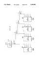
- FIG. 5 illustrates the power levels in an illustrative eight-element distribution network beamformer in accordance with the embodiment of FIG. 2;
- FIG. 6 illustrates an extension of the FIG. 2 embodiment to support formation of multiple beams.
- Apparatus for use in a phased array microwave antenna includes radiating elements, transmit/receive (T/R) modules, hybrid couplers with unequal coupling values, and identical, N:1 equal-amplitude-split combiners, where N is the number of radiating elements in a column of the phased array.
- a phased array antenna 150 includes a plurality of radiators 152 mounted on a surface 160, which surface 160 may conform to the curved outer surface of the skin of an aircraft (not shown).
- Each radiator 152 is fed by a corresponding T/R module 154 attached to the inner side opposite surface 160.
- T/R modules 154 are driven by an RF feed network of RF power dividers comprising elevation feeds 156a and azimuth feeds 156b, which provide RF signals to each of the T/R modules 154.
- Phase information is supplied to each T/R module 154 through the system controller 158.
- System controller 158 originates the RF feed signals to the RF power dividers in feeds 156a and 156b, as well as control signals and voltages to the plurality of T/R modules 154.
- the apparatus includes radiating element 10, T/R module 12, unequal-split power coupler 14, first and second N:1 equal-split combiners 16 and 18, and azimuth beamforming networks 20 and 22. Although only one radiating element 10, one T/R module 12, and one power coupler 14 are shown, it should be noted that each input of combiner 16 and the corresponding input of combiner 18 is coupled to a similar combination of radiating element 10, T/R module 12 and power coupler 14.
- the totality of radiating elements 10 are preferably arranged in a linear array, typically forming a single column along a two-dimensional array of elements of the type shown in FIG. 1, and the positioning of these elements 10 along the linear array corresponds, in the preferred configuration, to the input positions of combiners 16 and 18.
- radiating element 10 may comprise a patch radiator on a planar or curved surface which is formed by a multiplicity of such elements 10.
- T/R module 12 illustratively comprises a level set attenuator 40, a phase shifter 38, a T/R switch 36, a low noise amplifier 32 in the receive path, a high power amplifier 34 in the transmit path, and a circulator 30 for the appropriate steering of the transmit and receive signals.
- Attenuator 40 is preferably a programmable attenuator for which different levels of attenuation may be established for the transmit and receive modes.
- Attenuator 40 may comprise a first attenuator in the combined transmit/receive path, and a second attenuator in the receive path such that the attenuation on receive is the sum of these first and second attenuators.
- Phase shifter 38 is, by way of example, a 6-bit phase shifter.
- Unequal-split power coupler 14 is illustratively an overlay hybrid coupler. This device can provide a coupling value from 3 dB to in excess of 40 dB.
- Combiners 16 and 18 are illustratively 64:1 equal-split combiners.
- a preferred configuration of a 32:1 equal-split combiner, which may comprise half of the illustrative 64:1 combiner 16 or combiner 18, is shown in greater detail in FIG. 3.
- Azimuth beamforming networks 20 and 22 are beamformers for shaping in azimuth the beams formed by combiners 16 and 18, respectively.
- the inputs to beamformers 20 and 22 shown unconnected in FIG. 2 are, in the full implementation of a two-dimensional phased array antenna system, connected, respectively, to other N:1 combiners, not explicitly shown in FIG. 2, corresponding to other columns in the array.
- combiners 16 and 18 are described as equal-split combiners, this limitation is driven by the requirement that the beamformer of the present invention transmits a uniform taper. Absent this requirement, combiners 14 and 16 may be configured as identical N:1 combiners having a predetermined taper. Such combiners 16 and 18 would then form distinct beams on receive by virtue of the unequal power splits provided by the N power couplers 14.
- radiator 10 and T/R module 12 are combined into an "attennule" architecture, which may be plugged into a socket on a circuit board (not shown) underlying the array, thereby positioning radiator 10 in the plane of the array.
- the circuit board may comprise a multilayer structure including combiners 16 and 18 fabricated as stripline or microstrip conductors, and unequal-split couplers 14 fabricated as overlay hybrid couplers. It will be seen that by using this arrangement, the illumination taper may be altered by replacement of the overlay hybrid couplers and by adjustment of the attenuator in the T/R module.
- a power combiner 16' which may represent half of combiner 16 described in relation to FIG. 2.
- Combiner 16' comprises a corporate feed structure of equal-split power combiners.
- sixteen equal-split power combiners 24e feed eight equal-split power combiners 24d, which feed four equal-split power combiners 24c, which feed two equal-split power combiners 24b, which feed a single equal-split power combiner 24a.
- such configuration additionally provides an equal phase relationship of all signals through combiner 16'.
- loss elements in the set of paths between a radiating element 10 and a pair of combiners 16 and 18.
- Such loss elements include attenuator 40 (part of T/R module 12 as shown in FIG. 2) and coupler 14.
- A represents the dB loss through attenuator 40
- B represents the dB loss along the "through” path of coupler 14
- Attenuator 40 is set at 1.59 dB, and power coupler 14 provides an attenuation of 1.42 dB along the through path and 5.54 dB along the coupled path.
- the accumulated loss presented at a first input of combiner 16 is 3.01 dB, and the accumulated loss presented at the corresponding input of combiner 18 is 7.13 dB.
- FIG. 5 there is shown an illustrative eight-element distribution network beamformer including coupling values and attenuation levels for exemplary illumination tapers.
- This figure illustrates an 8:1 equal-split combiner 42 comprising four 2:1 equal-split power combiners 44c, two 2:1 equal-split power combiners 44b and one 2:1 equal-split power combiner 44a.
- Eight attenuators 48a-48h are electrically connected to eight power couplers 46a-46h, respectively, and the coupled outputs therefrom are individually connected to the eight inputs to combiner 42.
- FIG. 5 it will be understood from FIG. 2 and the accompanying text, that the through paths from couplers 46a-46h are connected to another 8:1 equal-split combiner, similar to combiner 42.
- the beamformer will provide on receive a portion of a Taylor weighting on the through paths of power couplers 46a-46h, and a portion of a Bayliss weighting on the coupled paths of power couplers 46a-46h. Furthermore, the beamformer will provide on transmit a uniform taper on the through paths of power couplers 46a-46h, and, therefore, a Bayliss ⁇ Taylor weighting on the coupled paths.
- the values of attenuators 48a-48h on transmit may be determined for either the uniform (through path) taper or the Bayliss ⁇ Taylor (coupled path) taper.
- the additional attenuations for the receive mode may be determined for either the Taylor (through path) taper or the Bayliss (coupled path) taper.
- the design of a dual beamforming system in accordance with the present invention entails three steps. First, the N power ratios of the first and second beams for all N individual elements along the linear array are determined, and power couplers 46a-46h and selected therefrom. Secondly, the power ratios among the elements of one of the linear arrays are determined on transmit and, in consideration of the attenuations through power couplers 46a-46h, the transmit mode levels in the corresponding attenuators 48a-48h are set.
- the power ratios among the elements of one of the linear arrays are determined on receive and, in consideration of the attenuations through power couplers 46a-46h and attenuators 48a-48h in the transmit mode, the additional attenuation levels in the corresponding attenuators 48a-48h on receive are set.
- the following paragraphs detail the method by which power coupler 46a and the transmit and receive levels of attenuator 48a are selected.
- the normalized power of the Bayliss taper at the element corresponding to attenuator 48a and power coupler 46a and is 0.00177
- the normalized power of the Taylor taper at this element is 0.00325.
- this device In order to realize the necessary power division through power coupler 46a, this device must provide an attenuation of 1.88 dB on the through path (Taylor weighting) and 4.53 dB on the coupled path (Bayliss weighting).
- the power divisions through power couplers 46b-46h are found, and the coupling values therethrough are determined.
- the values of attenuators 48a-48h are determined for the transmit mode. Considering the through paths of couplers 46a-46h (the uniform illumination taper on transmit), the maximum attenuation is 3.01 dB through coupler 46c. Accordingly, attenuator 48c is set to 0.00 dB on transmit, and each of the other attenuators 48a-48b and 48d-48h are set to values which, when added to the through path attenuation of their corresponding power couplers, provide 3.01 dB on transmit.
- Attenuator 48a is set to 1.12 dB on transmit for a total attenuation therethrough of 3.01 dB (neglecting rounding errors).
- the values of attenuators 48a-48h are determined for the receive mode. Considering the values of normalized power on receive, the maximum value is 1.00, associated with the Taylor weighting at the element corresponding to attenuator 48h and power coupler 46h. Accordingly, no additional attenuation is added to attenuator 48h on receive. Thus attenuator 48h has a value of 2.92 dB on both transmit and receive, and the through path attenuation on receive (Taylor taper) is 3.01 dB.
- FIG. 6 there is shown an additional embodiment wherein the concept of the present invention is extended to a phased array radar system forming more than two beams simultaneously on receive.
- Radiating element 10 is coupled to T/R module 12, in a manner similar to the FIG. 2 embodiment, and the output of T/R module 12 is applied to unequal-split power coupler 50a.
- the through signal from coupler 50a is applied to one of the N inputs of N:1 equal-split combiner 52a, and the coupled signal from coupler 50a is applied to a second unequal-split power coupler 50b.
- the through signal from coupler 50b is applied to an input of a second N:1 equal-split combiner 52b, corresponding to the above-mentioned input of combiner 52a, and the coupled signal from coupler 50b is applied to a third unequal-split power coupler 50c.
- any number of equal-split combiners 52a, 52b, 52c, . . . may be provided so as to form an expanded number of beams from a single radiating element 10 and T/R module 12.
- a similar configuration of radiating elements 10, T/R modules 12, and unequal-split power couplers 50a, 50b, 50c, 50d, . . . are applied to the N terminals of equal-split combiners 52a, 52b, 52c, 52d, . . . , to form multiple beams from a linear array of radiating elements 10.
Landscapes
- Engineering & Computer Science (AREA)
- Computer Networks & Wireless Communication (AREA)
- Physics & Mathematics (AREA)
- General Physics & Mathematics (AREA)
- Radar, Positioning & Navigation (AREA)
- Remote Sensing (AREA)
- Variable-Direction Aerials And Aerial Arrays (AREA)
Abstract
Description
Claims (16)
Priority Applications (1)
| Application Number | Priority Date | Filing Date | Title |
|---|---|---|---|
| US07/813,248 US5166690A (en) | 1991-12-23 | 1991-12-23 | Array beamformer using unequal power couplers for plural beams |
Applications Claiming Priority (1)
| Application Number | Priority Date | Filing Date | Title |
|---|---|---|---|
| US07/813,248 US5166690A (en) | 1991-12-23 | 1991-12-23 | Array beamformer using unequal power couplers for plural beams |
Publications (1)
| Publication Number | Publication Date |
|---|---|
| US5166690A true US5166690A (en) | 1992-11-24 |
Family
ID=25211872
Family Applications (1)
| Application Number | Title | Priority Date | Filing Date |
|---|---|---|---|
| US07/813,248 Expired - Lifetime US5166690A (en) | 1991-12-23 | 1991-12-23 | Array beamformer using unequal power couplers for plural beams |
Country Status (1)
| Country | Link |
|---|---|
| US (1) | US5166690A (en) |
Cited By (41)
| Publication number | Priority date | Publication date | Assignee | Title |
|---|---|---|---|---|
| US5276452A (en) * | 1992-06-24 | 1994-01-04 | Raytheon Company | Scan compensation for array antenna on a curved surface |
| US5327147A (en) * | 1991-07-26 | 1994-07-05 | Alcatel Espace | Microwave array antenna having sources of different widths |
| EP0624008A2 (en) * | 1993-05-07 | 1994-11-09 | Space Systems / Loral, Inc. | Mobile communication satellite payload |
| US5539415A (en) * | 1994-09-15 | 1996-07-23 | Space Systems/Loral, Inc. | Antenna feed and beamforming network |
| US5570098A (en) * | 1993-08-12 | 1996-10-29 | Northern Telecom Limited | Base station antenna arrangement |
| US5576717A (en) * | 1993-08-12 | 1996-11-19 | Northern Telecom Limited | Base station antenna arrangement |
| US5596329A (en) * | 1993-08-12 | 1997-01-21 | Northern Telecom Limited | Base station antenna arrangement |
| EP0790660A2 (en) * | 1996-02-15 | 1997-08-20 | Daimler-Benz Aerospace Aktiengesellschaft | Directional coupler for high frequency range |
| US5661489A (en) * | 1996-04-26 | 1997-08-26 | Questech, Inc. | Enhanced electronically steerable beam-forming system |
| US5714957A (en) * | 1993-08-12 | 1998-02-03 | Northern Telecom Limited | Base station antenna arrangement |
| US5771017A (en) * | 1993-08-12 | 1998-06-23 | Northern Telecom Limited | Base station antenna arrangement |
| US5959578A (en) * | 1998-01-09 | 1999-09-28 | Motorola, Inc. | Antenna architecture for dynamic beam-forming and beam reconfigurability with space feed |
| WO2000064007A1 (en) * | 1999-04-20 | 2000-10-26 | Sonetech Corporation | Determining and forming delayed waveforms |
| US6175331B1 (en) * | 1999-04-20 | 2001-01-16 | Sonetech Corporation | Method and apparatus for determining and forming delayed waveforms for forming radio frequency transmitting or receiving beams for an array of radio frequency transmitting or receiving elements |
| US6218985B1 (en) * | 1999-04-15 | 2001-04-17 | The United States Of America As Represented By The Secretary Of The Navy | Array synthesis method |
| US6429816B1 (en) | 2001-05-04 | 2002-08-06 | Harris Corporation | Spatially orthogonal signal distribution and support architecture for multi-beam phased array antenna |
| WO2003052449A2 (en) * | 2001-12-14 | 2003-06-26 | Raytheon Company | Back-up aid indicator |
| US6757267B1 (en) * | 1998-04-22 | 2004-06-29 | Koninklijke Philips Electronics N.V. | Antenna diversity system |
| US6975263B1 (en) * | 1998-06-24 | 2005-12-13 | Combitech Traffic Systems Ab | Device for position determination by means of radio waves |
| US20060055604A1 (en) * | 2004-09-14 | 2006-03-16 | Koenig Mary K | Multiple element patch antenna and electrical feed network |
| DE102007037252A1 (en) * | 2007-08-07 | 2009-02-12 | Forschungsgesellschaft für Angewandte Naturwissenschaften e.V.(FGAN) | Antenna element's amplitude adjusting method for radar, involves distributing amplitude adjustment between transmitter and/or receiver modules and supply network such that predefined portion of selected antenna element weight is taken |
| US20100214171A1 (en) * | 2009-02-24 | 2010-08-26 | Clifton Quan | Low cost multi-channel thinned tr module architecture |
| US20110248796A1 (en) * | 2010-04-09 | 2011-10-13 | Raytheon Company | Rf feed network for modular active aperture electronically steered arrays |
| CN103022698A (en) * | 2012-12-21 | 2013-04-03 | 四川九洲电器集团有限责任公司 | System allowing for phased-array amplitude weighting |
| US20130321206A1 (en) * | 2012-05-29 | 2013-12-05 | Chang Donald C D | Interference rejections of satellite ground terminal with orthogonal beams |
| CN103492900A (en) * | 2011-04-20 | 2014-01-01 | 飞思卡尔半导体公司 | Antenna device, amplifier and receiver circuit, and radar circuit |
| US9184498B2 (en) | 2013-03-15 | 2015-11-10 | Gigoptix, Inc. | Extending beamforming capability of a coupled voltage controlled oscillator (VCO) array during local oscillator (LO) signal generation through fine control of a tunable frequency of a tank circuit of a VCO thereof |
| WO2016014188A1 (en) * | 2014-07-25 | 2016-01-28 | Raytheon Company | Electronically reconfigurable, piecewise-linear, scalable analog monopulse feeding network |
| US9275690B2 (en) | 2012-05-30 | 2016-03-01 | Tahoe Rf Semiconductor, Inc. | Power management in an electronic system through reducing energy usage of a battery and/or controlling an output power of an amplifier thereof |
| US9509351B2 (en) | 2012-07-27 | 2016-11-29 | Tahoe Rf Semiconductor, Inc. | Simultaneous accommodation of a low power signal and an interfering signal in a radio frequency (RF) receiver |
| US9531070B2 (en) | 2013-03-15 | 2016-12-27 | Christopher T. Schiller | Extending beamforming capability of a coupled voltage controlled oscillator (VCO) array during local oscillator (LO) signal generation through accommodating differential coupling between VCOs thereof |
| US20170040710A1 (en) * | 2015-08-09 | 2017-02-09 | The United States Of America As Represented By The Secretary Of The Navy | System including a hybrid active array |
| US20170062927A1 (en) * | 2014-05-12 | 2017-03-02 | Huawei Technologies Co., Ltd. | Antenna system |
| US9666942B2 (en) | 2013-03-15 | 2017-05-30 | Gigpeak, Inc. | Adaptive transmit array for beam-steering |
| US9716315B2 (en) | 2013-03-15 | 2017-07-25 | Gigpeak, Inc. | Automatic high-resolution adaptive beam-steering |
| US9722310B2 (en) | 2013-03-15 | 2017-08-01 | Gigpeak, Inc. | Extending beamforming capability of a coupled voltage controlled oscillator (VCO) array during local oscillator (LO) signal generation through frequency multiplication |
| US9780449B2 (en) | 2013-03-15 | 2017-10-03 | Integrated Device Technology, Inc. | Phase shift based improved reference input frequency signal injection into a coupled voltage controlled oscillator (VCO) array during local oscillator (LO) signal generation to reduce a phase-steering requirement during beamforming |
| US9837714B2 (en) | 2013-03-15 | 2017-12-05 | Integrated Device Technology, Inc. | Extending beamforming capability of a coupled voltage controlled oscillator (VCO) array during local oscillator (LO) signal generation through a circular configuration thereof |
| CN109119765A (en) * | 2017-06-22 | 2019-01-01 | 康普技术有限责任公司 | Cellular communication system containing the aerial array with enhancing half-power beam width control |
| US20220342035A1 (en) * | 2021-04-23 | 2022-10-27 | Nuro, Inc. | Radar system for an autonomous vehicle |
| US20230246331A1 (en) * | 2018-07-02 | 2023-08-03 | Tubis Technology, Inc. | Adjustable unequal power combiner and switch |
Citations (1)
| Publication number | Priority date | Publication date | Assignee | Title |
|---|---|---|---|---|
| US4792805A (en) * | 1987-04-28 | 1988-12-20 | Hughes Aircraft Company | Multifunction active array |
-
1991
- 1991-12-23 US US07/813,248 patent/US5166690A/en not_active Expired - Lifetime
Patent Citations (1)
| Publication number | Priority date | Publication date | Assignee | Title |
|---|---|---|---|---|
| US4792805A (en) * | 1987-04-28 | 1988-12-20 | Hughes Aircraft Company | Multifunction active array |
Cited By (62)
| Publication number | Priority date | Publication date | Assignee | Title |
|---|---|---|---|---|
| US5327147A (en) * | 1991-07-26 | 1994-07-05 | Alcatel Espace | Microwave array antenna having sources of different widths |
| US5276452A (en) * | 1992-06-24 | 1994-01-04 | Raytheon Company | Scan compensation for array antenna on a curved surface |
| US5623269A (en) * | 1993-05-07 | 1997-04-22 | Space Systems/Loral, Inc. | Mobile communication satellite payload |
| EP0624008A2 (en) * | 1993-05-07 | 1994-11-09 | Space Systems / Loral, Inc. | Mobile communication satellite payload |
| EP0624008A3 (en) * | 1993-05-07 | 1995-01-18 | Loral Space Systems Inc | Mobile communication satellite payload. |
| US5422647A (en) * | 1993-05-07 | 1995-06-06 | Space Systems/Loral, Inc. | Mobile communication satellite payload |
| EP1133002A1 (en) * | 1993-05-07 | 2001-09-12 | Space Systems / Loral, Inc. | Mobile communication satellite payload |
| US5548292A (en) * | 1993-05-07 | 1996-08-20 | Space Systems/Loral | Mobile communication satellite payload |
| US5570098A (en) * | 1993-08-12 | 1996-10-29 | Northern Telecom Limited | Base station antenna arrangement |
| US5596329A (en) * | 1993-08-12 | 1997-01-21 | Northern Telecom Limited | Base station antenna arrangement |
| US5576717A (en) * | 1993-08-12 | 1996-11-19 | Northern Telecom Limited | Base station antenna arrangement |
| US5714957A (en) * | 1993-08-12 | 1998-02-03 | Northern Telecom Limited | Base station antenna arrangement |
| US5771017A (en) * | 1993-08-12 | 1998-06-23 | Northern Telecom Limited | Base station antenna arrangement |
| US5539415A (en) * | 1994-09-15 | 1996-07-23 | Space Systems/Loral, Inc. | Antenna feed and beamforming network |
| EP0790660A2 (en) * | 1996-02-15 | 1997-08-20 | Daimler-Benz Aerospace Aktiengesellschaft | Directional coupler for high frequency range |
| EP0790660A3 (en) * | 1996-02-15 | 1998-06-03 | Daimler-Benz Aerospace Aktiengesellschaft | Directional coupler for high frequency range |
| US5825260A (en) * | 1996-02-15 | 1998-10-20 | Daimler-Benz Aerospace Ag | Directional coupler for the high-frequency range |
| US5661489A (en) * | 1996-04-26 | 1997-08-26 | Questech, Inc. | Enhanced electronically steerable beam-forming system |
| US5959578A (en) * | 1998-01-09 | 1999-09-28 | Motorola, Inc. | Antenna architecture for dynamic beam-forming and beam reconfigurability with space feed |
| US6757267B1 (en) * | 1998-04-22 | 2004-06-29 | Koninklijke Philips Electronics N.V. | Antenna diversity system |
| US6975263B1 (en) * | 1998-06-24 | 2005-12-13 | Combitech Traffic Systems Ab | Device for position determination by means of radio waves |
| US6218985B1 (en) * | 1999-04-15 | 2001-04-17 | The United States Of America As Represented By The Secretary Of The Navy | Array synthesis method |
| US6175331B1 (en) * | 1999-04-20 | 2001-01-16 | Sonetech Corporation | Method and apparatus for determining and forming delayed waveforms for forming radio frequency transmitting or receiving beams for an array of radio frequency transmitting or receiving elements |
| WO2000064007A1 (en) * | 1999-04-20 | 2000-10-26 | Sonetech Corporation | Determining and forming delayed waveforms |
| US6429816B1 (en) | 2001-05-04 | 2002-08-06 | Harris Corporation | Spatially orthogonal signal distribution and support architecture for multi-beam phased array antenna |
| WO2003052449A2 (en) * | 2001-12-14 | 2003-06-26 | Raytheon Company | Back-up aid indicator |
| US20030146826A1 (en) * | 2001-12-14 | 2003-08-07 | Viana Luis M. | Back-up aid indicator |
| WO2003052449A3 (en) * | 2001-12-14 | 2003-11-27 | Raytheon Co | Back-up aid indicator |
| US6873250B2 (en) | 2001-12-14 | 2005-03-29 | Raytheon Company | Back-up aid indicator using FMCW chirp signal or a time domain pulse signal |
| US7064713B2 (en) | 2004-09-14 | 2006-06-20 | Lumera Corporation | Multiple element patch antenna and electrical feed network |
| US20060055604A1 (en) * | 2004-09-14 | 2006-03-16 | Koenig Mary K | Multiple element patch antenna and electrical feed network |
| DE102007037252A1 (en) * | 2007-08-07 | 2009-02-12 | Forschungsgesellschaft für Angewandte Naturwissenschaften e.V.(FGAN) | Antenna element's amplitude adjusting method for radar, involves distributing amplitude adjustment between transmitter and/or receiver modules and supply network such that predefined portion of selected antenna element weight is taken |
| DE102007037252B4 (en) * | 2007-08-07 | 2009-04-09 | Forschungsgesellschaft für Angewandte Naturwissenschaften e.V.(FGAN) | Method and device for amplitude adjustment for antenna elements of an active, electronically controlled antenna system |
| US20100214171A1 (en) * | 2009-02-24 | 2010-08-26 | Clifton Quan | Low cost multi-channel thinned tr module architecture |
| US7965235B2 (en) * | 2009-02-24 | 2011-06-21 | Raytheon Company | Multi-channel thinned TR module architecture |
| TWI460923B (en) * | 2010-04-09 | 2014-11-11 | Raytheon Co | Feed network for antenna subarray and antenna subarray thereof |
| US20110248796A1 (en) * | 2010-04-09 | 2011-10-13 | Raytheon Company | Rf feed network for modular active aperture electronically steered arrays |
| US8427371B2 (en) * | 2010-04-09 | 2013-04-23 | Raytheon Company | RF feed network for modular active aperture electronically steered arrays |
| CN103492900A (en) * | 2011-04-20 | 2014-01-01 | 飞思卡尔半导体公司 | Antenna device, amplifier and receiver circuit, and radar circuit |
| CN103492900B (en) * | 2011-04-20 | 2016-09-21 | 飞思卡尔半导体公司 | Antenna assembly, amplifier and acceptor circuit and radar circuit |
| US20130321206A1 (en) * | 2012-05-29 | 2013-12-05 | Chang Donald C D | Interference rejections of satellite ground terminal with orthogonal beams |
| US9275690B2 (en) | 2012-05-30 | 2016-03-01 | Tahoe Rf Semiconductor, Inc. | Power management in an electronic system through reducing energy usage of a battery and/or controlling an output power of an amplifier thereof |
| US9509351B2 (en) | 2012-07-27 | 2016-11-29 | Tahoe Rf Semiconductor, Inc. | Simultaneous accommodation of a low power signal and an interfering signal in a radio frequency (RF) receiver |
| CN103022698B (en) * | 2012-12-21 | 2016-01-27 | 四川九洲电器集团有限责任公司 | The system of phase array amplitude weighting can be realized |
| CN103022698A (en) * | 2012-12-21 | 2013-04-03 | 四川九洲电器集团有限责任公司 | System allowing for phased-array amplitude weighting |
| US9780449B2 (en) | 2013-03-15 | 2017-10-03 | Integrated Device Technology, Inc. | Phase shift based improved reference input frequency signal injection into a coupled voltage controlled oscillator (VCO) array during local oscillator (LO) signal generation to reduce a phase-steering requirement during beamforming |
| US9184498B2 (en) | 2013-03-15 | 2015-11-10 | Gigoptix, Inc. | Extending beamforming capability of a coupled voltage controlled oscillator (VCO) array during local oscillator (LO) signal generation through fine control of a tunable frequency of a tank circuit of a VCO thereof |
| US9531070B2 (en) | 2013-03-15 | 2016-12-27 | Christopher T. Schiller | Extending beamforming capability of a coupled voltage controlled oscillator (VCO) array during local oscillator (LO) signal generation through accommodating differential coupling between VCOs thereof |
| US9837714B2 (en) | 2013-03-15 | 2017-12-05 | Integrated Device Technology, Inc. | Extending beamforming capability of a coupled voltage controlled oscillator (VCO) array during local oscillator (LO) signal generation through a circular configuration thereof |
| US9666942B2 (en) | 2013-03-15 | 2017-05-30 | Gigpeak, Inc. | Adaptive transmit array for beam-steering |
| US9716315B2 (en) | 2013-03-15 | 2017-07-25 | Gigpeak, Inc. | Automatic high-resolution adaptive beam-steering |
| US9722310B2 (en) | 2013-03-15 | 2017-08-01 | Gigpeak, Inc. | Extending beamforming capability of a coupled voltage controlled oscillator (VCO) array during local oscillator (LO) signal generation through frequency multiplication |
| US10205236B2 (en) * | 2014-05-12 | 2019-02-12 | Huawei Technologies Co., Ltd. | Antenna system |
| US20170062927A1 (en) * | 2014-05-12 | 2017-03-02 | Huawei Technologies Co., Ltd. | Antenna system |
| US9502766B2 (en) | 2014-07-25 | 2016-11-22 | Raytheon Company | Electronically reconfigurable, piecewise-linear, scalable analog monopulse network |
| WO2016014188A1 (en) * | 2014-07-25 | 2016-01-28 | Raytheon Company | Electronically reconfigurable, piecewise-linear, scalable analog monopulse feeding network |
| US9742075B2 (en) * | 2015-08-09 | 2017-08-22 | The United States Of America As Represented By The Secretary Of The Navy | System including a hybrid active array |
| US20170040710A1 (en) * | 2015-08-09 | 2017-02-09 | The United States Of America As Represented By The Secretary Of The Navy | System including a hybrid active array |
| CN109119765A (en) * | 2017-06-22 | 2019-01-01 | 康普技术有限责任公司 | Cellular communication system containing the aerial array with enhancing half-power beam width control |
| US20230246331A1 (en) * | 2018-07-02 | 2023-08-03 | Tubis Technology, Inc. | Adjustable unequal power combiner and switch |
| US12113296B2 (en) * | 2018-07-02 | 2024-10-08 | Tubis Technology, Inc. | Adjustable unequal power combiner and switch |
| US20220342035A1 (en) * | 2021-04-23 | 2022-10-27 | Nuro, Inc. | Radar system for an autonomous vehicle |
Similar Documents
| Publication | Publication Date | Title |
|---|---|---|
| US5166690A (en) | Array beamformer using unequal power couplers for plural beams | |
| US4849763A (en) | Low sidelobe phased array antenna using identical solid state modules | |
| US4792805A (en) | Multifunction active array | |
| US5276452A (en) | Scan compensation for array antenna on a curved surface | |
| US9124361B2 (en) | Scalable, analog monopulse network | |
| US4316192A (en) | Beam forming network for butler matrix fed circular array | |
| US5151706A (en) | Apparatus for electronically controlling the radiation pattern of an antenna having one or more beams of variable width and/or direction | |
| US5162803A (en) | Beamforming structure for modular phased array antennas | |
| US4124852A (en) | Phased power switching system for scanning antenna array | |
| US5017927A (en) | Monopulse phased array antenna with plural transmit-receive module phase shifters | |
| DE69323281T2 (en) | Active phase controlled transmit group antenna | |
| EP1215751B1 (en) | Calibration method of an array antenna | |
| US5977910A (en) | Multibeam phased array antenna system | |
| US7791536B2 (en) | High power phased array antenna system and method with low power switching | |
| WO1999036992A3 (en) | Array antenna having multiple independently steered beams | |
| KR950024370A (en) | Active transmit phased array antenna with amplitude data. | |
| EP0468662B1 (en) | Plural frequency matrix multiplexer | |
| US5548295A (en) | Multishaped beam direct radiating array antenna | |
| USH1773H (en) | Ultra-wideband active electronically scanned antenna | |
| US6590531B2 (en) | Planar, fractal, time-delay beamformer | |
| US5302953A (en) | Secondary radar antenna operating in S mode | |
| EP2985838B1 (en) | Systems and methods for high power microwave combining and switching | |
| US11121462B2 (en) | Passive electronically scanned array (PESA) | |
| US3525995A (en) | Amplitude tapering,nonsymmetrical binary feed networks for highpower hf phased arrays | |
| US6255990B1 (en) | Processor for two-dimensional array antenna |
Legal Events
| Date | Code | Title | Description |
|---|---|---|---|
| AS | Assignment |
Owner name: RAYTHEON COMPANY, MASSACHUSETTS Free format text: ASSIGNMENT OF ASSIGNORS INTEREST.;ASSIGNORS:CARLSON, THOMAS F.;GLICKMAN, ALAN J.;REEL/FRAME:005976/0431 Effective date: 19911219 |
|
| STCF | Information on status: patent grant |
Free format text: PATENTED CASE |
|
| FEPP | Fee payment procedure |
Free format text: PAYOR NUMBER ASSIGNED (ORIGINAL EVENT CODE: ASPN); ENTITY STATUS OF PATENT OWNER: LARGE ENTITY |
|
| FPAY | Fee payment |
Year of fee payment: 4 |
|
| AS | Assignment |
Owner name: AIR FORCE, UNITED STATES, NEW YORK Free format text: CONFIRMATORY LICENSE;ASSIGNOR:RAYTHEON COMPANY;REEL/FRAME:009624/0390 Effective date: 19920129 |
|
| FEPP | Fee payment procedure |
Free format text: PAYER NUMBER DE-ASSIGNED (ORIGINAL EVENT CODE: RMPN); ENTITY STATUS OF PATENT OWNER: LARGE ENTITY Free format text: PAYOR NUMBER ASSIGNED (ORIGINAL EVENT CODE: ASPN); ENTITY STATUS OF PATENT OWNER: LARGE ENTITY |
|
| FPAY | Fee payment |
Year of fee payment: 8 |
|
| FEPP | Fee payment procedure |
Free format text: PAYER NUMBER DE-ASSIGNED (ORIGINAL EVENT CODE: RMPN); ENTITY STATUS OF PATENT OWNER: LARGE ENTITY Free format text: PAYOR NUMBER ASSIGNED (ORIGINAL EVENT CODE: ASPN); ENTITY STATUS OF PATENT OWNER: LARGE ENTITY |
|
| FPAY | Fee payment |
Year of fee payment: 12 |