US5123087A - Geometric inference engine - Google Patents
Geometric inference engine Download PDFInfo
- Publication number
- US5123087A US5123087A US07/516,004 US51600490A US5123087A US 5123087 A US5123087 A US 5123087A US 51600490 A US51600490 A US 51600490A US 5123087 A US5123087 A US 5123087A
- Authority
- US
- United States
- Prior art keywords
- point
- displaying
- cursor
- points
- user
- Prior art date
- Legal status (The legal status is an assumption and is not a legal conclusion. Google has not performed a legal analysis and makes no representation as to the accuracy of the status listed.)
- Expired - Fee Related
Links
Images


Classifications
-
- G—PHYSICS
- G06—COMPUTING; CALCULATING OR COUNTING
- G06F—ELECTRIC DIGITAL DATA PROCESSING
- G06F3/00—Input arrangements for transferring data to be processed into a form capable of being handled by the computer; Output arrangements for transferring data from processing unit to output unit, e.g. interface arrangements
- G06F3/01—Input arrangements or combined input and output arrangements for interaction between user and computer
- G06F3/048—Interaction techniques based on graphical user interfaces [GUI]
- G06F3/0484—Interaction techniques based on graphical user interfaces [GUI] for the control of specific functions or operations, e.g. selecting or manipulating an object, an image or a displayed text element, setting a parameter value or selecting a range
- G06F3/04845—Interaction techniques based on graphical user interfaces [GUI] for the control of specific functions or operations, e.g. selecting or manipulating an object, an image or a displayed text element, setting a parameter value or selecting a range for image manipulation, e.g. dragging, rotation, expansion or change of colour
-
- G—PHYSICS
- G06—COMPUTING; CALCULATING OR COUNTING
- G06F—ELECTRIC DIGITAL DATA PROCESSING
- G06F3/00—Input arrangements for transferring data to be processed into a form capable of being handled by the computer; Output arrangements for transferring data from processing unit to output unit, e.g. interface arrangements
- G06F3/01—Input arrangements or combined input and output arrangements for interaction between user and computer
- G06F3/048—Interaction techniques based on graphical user interfaces [GUI]
- G06F3/0481—Interaction techniques based on graphical user interfaces [GUI] based on specific properties of the displayed interaction object or a metaphor-based environment, e.g. interaction with desktop elements like windows or icons, or assisted by a cursor's changing behaviour or appearance
- G06F3/04812—Interaction techniques based on cursor appearance or behaviour, e.g. being affected by the presence of displayed objects
-
- G—PHYSICS
- G06—COMPUTING; CALCULATING OR COUNTING
- G06F—ELECTRIC DIGITAL DATA PROCESSING
- G06F3/00—Input arrangements for transferring data to be processed into a form capable of being handled by the computer; Output arrangements for transferring data from processing unit to output unit, e.g. interface arrangements
- G06F3/01—Input arrangements or combined input and output arrangements for interaction between user and computer
- G06F3/048—Interaction techniques based on graphical user interfaces [GUI]
- G06F3/0484—Interaction techniques based on graphical user interfaces [GUI] for the control of specific functions or operations, e.g. selecting or manipulating an object, an image or a displayed text element, setting a parameter value or selecting a range
- G06F3/04842—Selection of displayed objects or displayed text elements
-
- G—PHYSICS
- G06—COMPUTING; CALCULATING OR COUNTING
- G06T—IMAGE DATA PROCESSING OR GENERATION, IN GENERAL
- G06T11/00—2D [Two Dimensional] image generation
- G06T11/20—Drawing from basic elements, e.g. lines or circles
-
- G—PHYSICS
- G06—COMPUTING; CALCULATING OR COUNTING
- G06T—IMAGE DATA PROCESSING OR GENERATION, IN GENERAL
- G06T17/00—Three dimensional [3D] modelling, e.g. data description of 3D objects
-
- Y—GENERAL TAGGING OF NEW TECHNOLOGICAL DEVELOPMENTS; GENERAL TAGGING OF CROSS-SECTIONAL TECHNOLOGIES SPANNING OVER SEVERAL SECTIONS OF THE IPC; TECHNICAL SUBJECTS COVERED BY FORMER USPC CROSS-REFERENCE ART COLLECTIONS [XRACs] AND DIGESTS
- Y10—TECHNICAL SUBJECTS COVERED BY FORMER USPC
- Y10S—TECHNICAL SUBJECTS COVERED BY FORMER USPC CROSS-REFERENCE ART COLLECTIONS [XRACs] AND DIGESTS
- Y10S706/00—Data processing: artificial intelligence
- Y10S706/902—Application using ai with detail of the ai system
- Y10S706/919—Designing, planning, programming, CAD, CASE
-
- Y—GENERAL TAGGING OF NEW TECHNOLOGICAL DEVELOPMENTS; GENERAL TAGGING OF CROSS-SECTIONAL TECHNOLOGIES SPANNING OVER SEVERAL SECTIONS OF THE IPC; TECHNICAL SUBJECTS COVERED BY FORMER USPC CROSS-REFERENCE ART COLLECTIONS [XRACs] AND DIGESTS
- Y10—TECHNICAL SUBJECTS COVERED BY FORMER USPC
- Y10S—TECHNICAL SUBJECTS COVERED BY FORMER USPC CROSS-REFERENCE ART COLLECTIONS [XRACs] AND DIGESTS
- Y10S715/00—Data processing: presentation processing of document, operator interface processing, and screen saver display processing
- Y10S715/961—Operator interface with visual structure or function dictated by intended use
- Y10S715/964—CAD or CAM, e.g. interactive design tools
Definitions
- the present invention relates generally to drawing programs and computer-aided drafting (CAD) systems and, more particularly, to precise cursor positioning and screen feedback techniques for creating and manipulating graphic objects.
- CAD computer-aided drafting
- CAD computer graphics
- the use of computer graphics is particularly well suited for automating designing and drafting techniques.
- CAD is like a word processor for drawings. Instead of pen and paper, the CAD user employs a computer keyboard and a mouse, light pen, digitizer tablet, or some other pointing device to create an electronic description of a drawing in the computer's memory. This image is displayed on a monitor and stored on a disk. When the user is satisfied with a drawing, he or she obtains a "hardcopy" by sending the stored image to an output device such as a plotter.
- CAD CAD
- a precise mathematical definition facilitating storage in the computer.
- This also allows the computer to perform complex manipulations and test relations between objects. For example, when an object's dimensions are specified to the computer, the user can view any side of the object to see how it will look after construction.
- the user draws by entering, either by keyboard or pointing device, the location of an object's "control points.” For example, if the user wants to draw a line (line segment), he or she types in or points to the starting and ending points.
- the computer displays a line defined by these control points.
- the computer can infer control points from what the user enters. For example, the user may enter a starting point, length, and angle. From this input, the computer calculates the second control point before displaying the line.
- keyboard entry allows for the precise input of most geometric objects, it is usually not the most efficient means by which the user may communicate with a computer. For example, it would be a tedious task, at best, to draw the entire floor plan of a simple house by keyboard entry. Entering locations with a pointing device, while much faster, relies too much upon the skill of the user for accuracy. As a result, there is much interest in developing techniques by which CAD users may efficiently communicate with computers without sacrificing precision.
- Sutherland describes a positioning technique based upon the use of a light pen (Sutherland, Sketchpad: A Man-Machine Graphic Communication System, Proceedings-Spring Joint Computer Conference, 1963).
- the Sutherland Sketchpad system allows a user to communicate rapidly with a computer through the medium of line drawing.
- the Sketchpad system uses a light pen for the placement of a drawing cursor. To compensate for the inaccuracy created by freehand pointing, the exact location of the light pen is ignored in favor of a "pseudo-pen" location which is exactly on an object aimed at. In other words, object, the computer assumes that the user wants to point to that object. If no object is aimed at, the pseudopen location and actual pen location are identical. Thus, the Sketchpad system compensates for a user's imprecise cursor placement by constraining or snapping control points onto an existing object.
- This invention provides a computer-aided drafting system which includes precise cursor positioning and screen feedback techniques for creating and manipulating graphic objects.
- the techniques include: (1) the automatic recognition of interesting points; (2) the use of screen messages; (3) the addition of a secondary cursor; (4) the creation of temporary geometry; (5) the examination for interesting points which arise from actual geometry, temporary geometry, and/or the interaction of actual and temporary geometry; and (6) precise transformations accomplished with the assistance of interesting points.
- FIG. 1 is a simplified functional block diagram of a computer system in which the present invention may be embodied.
- FIGS. 2A-B illustrate a simple example of locating an interesting point, the endpoint for a line.
- FIGS. 3A-B illustrate the creation of new interesting points from the construction of temporary geometry.
- FIGS. 4A-B illustrate the use of temporary construction lines to maintain precise angular relations for normal creation angles.
- FIGS. 5A-B illustrate the use of temporary construction lines to maintain precise angular relations for additional creation angles.
- FIGS. 6A-C illustrate the use of temporary construction lines to find tangents.
- FIGS. 7A-B illustrate the use of temporary construction line to find perpendiculars.
- FIG. 7C illustrates the use of temporary construction lines to find angles in between a tangent and a perpendicular.
- FIGS. 8A-B illustrate the use of temporary construction lines to find offsets.
- FIG. 9 illustrates the use of a temporary construction line with a single vanishing point.
- FIGS. 10A-C illustrate the use of a temporary construction circle to maintain precise polar relationships.
- FIGS 11A-B illustrate the construction of temporary construction lines for tangents in conjunction with the maintenance of a set of active points.
- FIGS. 12A-B illustrate the determination of temporary construction lines for perpendiculars which depends upon the maintenance of a set of active points.
- FIG. 13 illustrates a simple grid point as an interesting point.
- FIG. 14 illustrates the interaction between a user-drawn line and a grid line.
- FIG. 15 illustrates the interaction between a temporary construct line and a grid line.
- FIGS. 16A-B illustrate a precise move transformation operation with the aid of interesting points.
- FIGS. 17A-B are flow diagrams for the ptSnap function.
- FIGS. 18A-B are flow diagrams for the snapTestObj function.
- FIG. 19 is a flow diagram for the snapAddObj function.
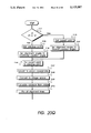
- FIG. 20A is a flow diagram for the null case arm in the ptSnap function.
- FIG. 20B is a flow diagram for the freepoint case arm in the ptSnap function.
- FIG. 20C is a flow diagram for the endpoints case arm in the ptSnap function.
- FIG. 20D is a flow diagram for the EVALPT macro.
- FIG. 20E is a flow diagram for the midpoints case arm in the ptSnap function.
- FIG. 20F is a flow diagram for the % (percent) points case arm in the ptSnap function.
- FIG. 20G is a flow diagram for the vertex points case arm in the ptSnap function.
- FIG. 20H is a flow diagram for the center points case arm in the ptSnap function.
- FIG. 20I is a flow diagram for the quadrant points case arm in the ptSnap function.
- FIG. 20J is a flow diagram for the intersections case arm in the ptSnap function.
- FIGS. 20K-L are flow diagrams for the tangents and perpendiculars case arm in the ptSnap function.
- FIGS. 20M-N are flow diagrams for part2 in the tangents and perpendiculars case arm in the ptSnap function.
- FIG. 20O is a flow diagram for the snap-onto-lines case arm in the ptSnap function.
- FIG. 20P is a flow diagram for the grid points case arm in the ptSnap function.
- FIGS. 20Q-R are flow diagrams for the align case arm in the ptSnap function.
- FIG. 20S is a flow diagram for the align t and p case arm in the ptSnap function.
- FIG. 20T is a flow diagram for the cleanup routine in the ptSnap function.
- the invention may be embodied on a computer system such as the system 100 of FIG. 1, which comprises a mouse 101, a keyboard 102, a fixed disk 103, a display monitor 104, an input/output controller 105, a central processor 106, and a main memory 107.
- the various components communicate through a system bus 108 or similar architecture.
- the user enters commands through the keyboard 102 and/or the mouse 101; the computer displays the image through the display monitor 104, such as a cathode ray tube or a printer.
- an appropriately programmed Macintosh personal computer (Apple Computers, Cupertino, Calif.) is used.
- the user constructs objects on the display monitor 104 with the mouse 101.
- the system emulates the drawing tools which are typically available to the draftsman, such as a compass, a ruler, a technical pen, a french curve, and a transfer screen.
- Each drawing is constructed from geometric objects which have precise mathematical definitions and, thus, are represented in the computer's memory 107.
- To draw a line for example, one need only specify its starting and ending points.
- a circle is constructed by specifying its center and a point on the circle. The accurate placement of these "control points" is crucial for the creation of geometric objects in CAD systems.
- the present invention recognizes that there are many types of interesting points which one needs for efficient designing and drafting and, therefore, provides a geometric inference engine which automatically locates these points.
- Interesting points are any geometric entity, parameter, or location which is of interest to the draftsman; types include midpoints, endpoints, intersections, vertices, tangents, perpendiculars, arc centers, and arc quadrant points.
- the system also indicates the exact nature of each and how it is found.
- the system locates nearby interesting point by examining all geometries close to the cursor. If there is a best interesting point nearby, the system displays it to the user by drawing an "X" (secondary cursor) over it with a message of how the point was found.
- X secondary cursor
- FIGS. 2A-B illustrate a simple case of locating an interesting point.
- the cursor 202 is not near any interesting points. However, once the cursor 202 moves sufficiently close to the end of the line 201, an interesting point is identified. As seen in FIG. 2B, the secondary cursor 203 snaps to the line's endpoint 205 and the message "endpoint" 204 is displayed. The system performs this detection automatically, i.e., without any additional user action.
- Prior systems provide minimal, if any, support for interesting points. For example, to interact with even the simplest type of interesting point, such as a midpoint, the user must enter a series of commands. Typically, the user must first select an object or group of objects. Then he or she must specify the type of the interesting point. Only after completing these steps, may the user interact with the point sought. Screen feedback is minimal. Moreover, the set of interesting points available in these systems is very limited--the user may select only those points which are intrinsic to the object or objects drawn.
- the locating of nearby interesting points is merely the initial inquiry of the geometric inference engine. If the system does not find an interesting point, it generates more geometry to see if this creates new interesting points. An example best demonstrates this feature.
- FIGS. 3A-B illustrate the construction of temporary geometry by the system to create new interesting points.
- cursor 302 moves no interesting points are encountered. Specifically, cursor 302 is not near any interesting points, such as endpoints or midpoint, which lie on the line 301.
- the system generates additional geometry by creating temporary construction lines 303, 313.
- These lines 303, 313 are termed "temporary geometry" to distinguish them from existing objects or actual geometry (e.g., line 306).
- the intersection 310 of these lines 303, 313 is near the location of the cursor 311.
- intersection 310 of temporary geometry As an interesting point. It indicates this to the user by snapping the secondary cursor 307 onto the intersection 310 and displaying the "intersect" message 308. As FIG. 3B indicates, this interesting point 310 is aligned vertically and horizontally with the endpoints 305, 312 of the existing line 306. Furthermore, the reason for the generation of the temporary construction lines is indicated by displaying "align" messages 304, 309 proximal to the endpoints 305, 312 which caused their creation.
- FIG. 4A illustrates the construction of a temporary construction line 404 at 0° relative to the endpoint 406 (interesting point) of an existing line 407.
- the "align" message 401 indicates to the user the reason for the creation of the temporary construction line 404.
- the "on” message 403 indicates that the secondary cursor 405 now lies on the temporary construction line 404.
- FIG. 4B illustrates the creation and display of a temporary construction line for 90°.
- the present invention provides a further refinement for the creation of temporary construction lines.
- the user may have many different alignment angles that he or she wishes to use; however, it is cumbersome, if not confusing, to display numerous alignment angles for a given point.
- the system solves this problem by providing two groups of alignment angles: 1) Normal creation angles and 2) Additional creation angles.
- the first group comprises the set of alignment angles which the user wants displayed automatically whenever the cursor traverses their path.
- the second group comprises the angles which are displayed automatically only under special circumstances.
- the user specifies a set of normal and additional creation angles or accepts the system's default values.
- FIGS. 5A-B illustrate the operation of additional creation angles.
- the endpoint 505 is the current point, i.e., the last point that the user entered.
- the geometric inference engine checks alignment of the cursor 501 with the current point 505 to see if it is near an additional creation angle.
- FIG. 5A an additional creation angle of 45° is set.
- the temporary construction line 506 is displayed along with the "align" message 504.
- the secondary cursor 503 moves onto the line 506 accompanied by the "on” message 502. Without this technique, the potential plethora of temporary construction lines would likely confuse the user and degrade the performance of the system.
- FIG. 5B illustrates the operation of an additional creation angle for 135°.
- Temporary construction lines are also useful for finding tangents, perpendiculars, and even angles in between tangents and perpendiculars.
- the user may wish to construct a line which lies tangent to an existing curve.
- FIGS. 6A-C illustrate this interaction.
- FIG. 6A represents the cursor 602 as it moves towards an interesting point of the arc 601.
- FIG. 6B As the cursor 609 passes by the arc 604, the geometric inference engine recognizes that the user may want to access the tangent from the arc's endpoint 603. In other words, the system recognizes that the cursor 609 is approaching an imaginary tangent from the endpoint 603. In response, the system creates the temporary construction line 607 and displays the "tangent" message 605. The secondary cursor 606 snaps onto the temporary construction line 607; juxtaposed is the "on" message 608 indicating that a control point, if placed now, would lie on the temporary construction line 607.
- FIG. 6C represents the completed illustration where the user draws a line to the arc's endpoint.
- FIG. 7A exemplifies locating a perpendicular 702 for an arc 701
- FIG. 7B shows a perpendicular 704 for a line 703.
- the geometric inference engine can locate any angle in between a tangent and a perpendicular.
- FIG. 7C for example, angles located between the tangent 705 and the perpendicular 706 are found.
- Offsets are temporary construction lines which parallel existing geometry.
- the degree of offset is user adjustable.
- FIGS. 8A-B illustrate offsets.
- the user moves the cursor 801 away from the line 802.
- the system displays the temporary construction line 803.
- the messages "on" 804 and "offset" 805 are displayed as feedback.
- FIG. 9 illustrates the interaction of actual geometry with a single vanishing point for line drawing.
- Temporary construction line 902 represents an imaginary axis which passes through the vanishing point 901 and the corner 903 of the box 904.
- the screen message "v.p.” 905 highlights the vanishing point 901
- "align” 906 indicates alignment with the corner 903
- "on” 907 signifies that the secondary cursor 908 has strayed away from the primary cursor 909 and onto the temporary construction line 902.
- FIGS. 10A-C illustrate the operation of temporary construction circles.
- the user wishes to extend the arc of the semicircle 1001.
- the temporary construction circle 1003 is displayed to aid the user in the placement of a new arc endpoint.
- the user need not concern himself with the arc radius which is held constant.
- FIG. 10C represents the completed drawing.
- FIG. 11A illustrates the locating of a tangent from any given point on a circle.
- This point 1102 becomes the current point.
- a temporary construction line 1104 is displayed along with the "tangent" message 1103.
- the secondary cursor 1106 migrates onto this line 1104; a confirmatory "on" message 1105 is displayed.
- FIG. 11B illustrates this concept for multiple objects.
- the user enters a point 1111 on the circle 1110.
- the point 1111 is now the current point.
- a temporary construction line 1115 is displayed along with "tangent" 1116.
- the cursor 1112 is also near the intersection 1118 of the line 1117 with the temporary construction line 1115.
- the geometric inference engine identifies this by placing the secondary cursor 1114 on the intersection 1118 and displaying the screen message "intersect" 1113.
- a temporary construction line once created, may interact with another existing object to create additional interesting points (e.g., intersection 1118).
- FIGS. 12A-B illustrate similar examples for perpendiculars.
- the geometric inference engine also identifies the interaction of grid lines with temporary or permanent geometry as interesting.
- FIG. 14 illustrates this interaction.
- the intersection of permanent geometry 1405 with grid line 1406 generates an interesting point 1403.
- the secondary cursor 1404 is attracted to this location 1403 and the "intersect" message 1402 is displayed as the cursor 1401 approaches.
- FIG. 15 illustrates the interaction of temporary geometry with grid lines.
- novel screen feedback techniques are provided to augment the utility of interesting points.
- Combining a secondary cursor with temporary geometries further increases drawing accuracy.
- the advantages are two-fold.
- the actual cursor need not be exactly at an "interesting location" to find interesting points. In other words, when the actual cursor is within the "hit radius" of an interesting location, the system may display interesting points without disrupting the position of the actual cursor.
- the secondary cursor is allowed to snap to the interesting point (or temporary geometry, if applicable) while the actual cursor maintains its current position. This allows even the novice user to interact precisely with interesting points.
- the secondary cursor gives the user a preview of where the actual cursor's position will map to when a control point is placed.
- transformation operations such as mirror, rotation, scale, and shear.
- transformations are accomplished by dragging images (XOR techniques) or by keyboard entry. Neither of these methods accomplish precise and efficient transformations.
- FIG. 16 illustrates a transformation operation with the aid of interesting points.
- the square 1601 is dragged (move transformation) to a new location with the aid of interesting points.
- the first interesting point 1605 the corner of the square 1601
- the second interesting point 1604 the intersection of the circle 1602 with the line 1603.
- ptSnap which is called whenever the mouse moves, is central to the operation of the geometric inference engine. For a given location on the screen, ptSnap locates the nearest geometry.
- ptSnap is passed p, a pointer structure variable of type snap -- record.
- the input values in p comprise the following:
- a) probe a variable of type Point which specifies the current screen location of the cursor.
- hitrad an integer variable which specifies the hit radius in pixels.
- c) method a character string which specifies the order in which different interesting points are tested by ptSnap; the string is initially defined globally but is changed locally within each individual function.
- nprev an integer variable which counts the number of points which are considered special.
- prevPt an array of points that the user wants alignment to, the last point (array member) being the location from where the alignment line is drawn.
- f) tangentV is an array of real numbers which is used to constrain operations, such as drawing or transformations, to lie within a particular tangent.
- the values ptSnap calculates and stores, i.e., the output variables, comprise the following:
- pt an array of three reals which specifies the actual point found.
- b) type an integer variable used to specify the ASCII value of the method used to find pt, for example, "i" (ASCII 105) for intersection or "t" (ASCII 116) for tangent.
- c) userch a character variable which allows the user to modify the method string.
- nobj an integer variable which specifies the number of objects used in a method. In freepoint, for example, nobj is equal to 0 since it is not related to any geometry. nobj is equal to 1 for endpoints and equal to 2 for intersections.
- obj an array of pointers to records of type gobject which specifies the objects used.
- objFlag an integer array used to specify whether an object is permanent or temporary geometry.
- g g niter: an integer variable used to count the number of iterations through the loop.
- objT an array which stores the t values for objects parametrically defined.
- tanvect tanvectsiz
- tanvectcnt store the tangent and perpendicular information for a given point.
- tanvect is a pointer variable to an array of reals where the tangent and perpendicular vectors are stored.
- tanvectsiz stores to size of the array, while tanvectcnt stores the number of such vectors.
- snap -- data a locally defined record. It comprises the following variables:
- bestpt, bestdist, and besttype store the best point found, its distance from the probe, and its type, respectively. These variables are collectively referred to as the best record.
- snapobj a pointer to snapobjs, an array which stores the objects found within the hit radius.
- FIGS. 17A-B illustrate the operation of ptSnap.
- the function sets up local copies of the snapdata and snapobjs records and initializes local variables.
- a hitbox is constructed by calculating the four corners of a box whose distance from the probe equals hitrad. In step 1703, these points are converted to world coordinates.
- the function snapTestObj is passed an object and the snap -- record pointer p. For each object within the hitbox, snapTestObj tests whether it is close enough to the user probe to be considered part of the active geometry.
- FIGS. 18A-B illustrate the steps of snapTestObj.
- the function checks whether the object passed is undetectable. For example, an object is undetectable while it is being created. For undetectable objects, the snapTestObj function returns; otherwise, it goes to step 1802 to check whether the object is unselectable. An object is unselectable if it is masked from the system. For example, the user may wish to mask out objects of certain colors, objects located in certain layers, or objects of a particular geometry. For unselectable objects, the function returns.
- the function tests whether a given object is capable of being displayed at the current view. If viewfail is set to true (non-zero), the function returns.
- Step 1804 confirms that the number of objects (nobj) does not exceed the object array, i.e., nobj is not equal to or greater than the maximum allowed objects.
- objHittest is called to make sure that the object passed to snapTestObj is within the hitbox. If it is not, then snapTestObj returns.
- snapTestObj checks whether the object is a container.
- An object which comprises a group of objects is a container.
- a box which comprises a group of lines, is a container.
- Primitive objects such as lines or arcs, are not containers. Since the geometric inference engine is only interested in snapping to primitive objects, containers are broken down into their primitive members. If at step 1806, an object is not a container, then at step 1807, snapTestObj checks whether the system is in copy mode. If so, then at step 1808, a copy is made. Otherwise, at step 1809, the function calls snapAddObj which adds the currently passed object to the object list.
- the function checks whether the container is a "clump," i.e., a container defined by four lines. If the container is a clump and copy mode is off, then at step 1814 the function enumerates all the objects in the clump by calling snapTestObj recursively.
- the copy flag is incremented before the objects of the container are enumerated at step 1812. This allows for a copy transformation, assuring that each object is properly placed.
- the copy flag is decremented and snapTestObj returns.
- FIG. 19 illustrates the snapAddObj function. It is called with an object, snap -- record, and a copy flag.
- the function checks whether the bounds of the object array are exceeded.
- the function gets the next object cell from p.
- the object field of the object cell is set equal to the object that is past in.
- the reference count of the object is incremented to facilitate freeing it later.
- snapAddObj returns to snapTestObj which returns to ptSnap.
- step 1704 in ptSnap all the actual geometry in the neighborhood of the probe is elucidated.
- ptSnap repeats this process for inference objects.
- ptSnap calls snapTestIObj, a function similar to snapTestObj except that the object types are not actual geometry.
- ptSnap seeks interesting points.
- a default method is defined globally, but the user may override this by pressing a key on the keyboard.
- ASCII 20 space character
- ptSnap checks the condition, defined by userch, first and returns if it exists. For example, if the global method is set to "miqp" (midpoints, intersections, quadrant points, and perpendiculars) and the user presses ⁇ t ⁇ (tangents), then ptSnap will change the method string to "t miqp.” In this case, tangents are sought and returned before all other interesting points.
- FIG. 17B illustrates the case statement which directs ptSnap's investigation for interesting points.
- ptSnap sequentially tests for different interesting point types, the order of search being specified by the character sequence in the method string. For each type of interesting point, the best point (bestpt), if any, is determined and returned to the geometric inference engine. However, for efficiency, ptSnap returns without any point when there is a timeout error, e.g., when the cursor moves to a new screen location before any best point is located.
- step 1711 The individual case arms for step 1711 will now be examined. For consistency, the C language convention of using single quotes for character values and double quotes for strings is adopted.
- step 2001 if the mouse button is not down and a valid point already exists, the function returns. Otherwise, if the best distance (bestdist) found is less than the hit radius (hitradSq) in step 2002, then at step 2004 the function returns the current point and object type as the bestpt and besttype.
- integers and squared values are favored to minimize slower floating point operations.
- bestdist is actually the square of the pixel distance from the probe to the bestpt.
- hitradSq the square of hitrad, is used to test the hit radius.
- the function After getting the best point and type at step 2004, the function goes to the cleanup routine in step 2006. However, if the best distance is not less than the hit radius in step 2002, then at step 2003 the function tests whether or not the character is null, i.e., ⁇ 0 ⁇ . If it is, the function falls through (continues y) to the next case arm--freepoint. Otherwise, it returns.
- FIG. 20B illustrates the steps of the freepoint case arm.
- type is set equal to ⁇ f ⁇
- number of objects is set equal to 0.
- the point is converted to world coordinates, and the function goes to cleanup at step 2013.
- step 1711 For the case of ch equal to ⁇ z ⁇ or ⁇ Z ⁇ , in step 1711, ptSnap goes to step 1714 which performs no operation (nops). No further steps are presently implemented for this case arm.
- FIG. 20C illustrates the steps for calculating endpoints.
- the function sets up a loop so that all objects are examined.
- the function loops. Otherwise, the function calculates the object's endpoints.
- ptSnap calculates endpoints by calling the EVALPT macro with the object index and a parametric value, t.
- FIG. 20D illustrates the steps of EVALPT.
- the function checks the parametric point, t, which is passed.
- the function returns. Otherwise, at step 2503, the point is converted to screen coordinates.
- the function returns. Otherwise, at step 2505, the best record (bestpt, bestdist, and besttype) is updated; the object's index is stored in the snapdata record; the number of objects is set equal to 1; and the function returns.
- ptSnap determines midpoints at step 1716.
- the process for midpoints is similar to that for endpoints.
- a loop is set up for all objects.
- Step 2032 checks whether the object is in the construction layer, while step 2033 checks whether the object is in the temporary layer. If either case is true, then the function loops to the next object. Otherwise, at step 2034, the index of the object and the t value of 0.5 are passed to EVALPT. The midpoint is returned.
- ptSnap determines the percent points at step 1717.
- Percent points allow the user to define intervals along an object as interesting points. For example, if the user wants the quarter intervals of a line to be interesting, he or she would enter 0.25 as the percent point.
- FIG. 20F illustrates, the computation for percent points is similar to the midpoint and endpoint processes.
- a loop is set up for all objects.
- the function loops to the next object. Otherwise, at step 2044, the object's index and percent point parameter is passed to EVALPT which returns any nearby percent point.
- ptSnap determines the vertex or visible points at step 1718.
- Vertex points are the handles or "hot points" for an object.
- FIG. 20G illustrates the operation for vertex points.
- a loop is established to examine all objects. If the object is in the temporary layer at step 2052, the function loops to the next object.
- the vertex points are determined in steps 2053-2057.
- a loop is established in step 2053 to examine vertex points computed from the point (pt) and snaprecord.
- the point is converted to screen coordinates.
- the distance from the probe to this point is tested against the bestdist. If the distance is not less than the bestdist, then the function returns. Since arc centers are preferably displayed as centers and not vertex points, at step 2056 the function filters out arc centers.
- the function stores the best record and object index, and sets the number of objects equal to 1 before returning.
- FIG. 20H illustrates the steps of this case arm.
- a loop is set up to test all control points (ctrPt).
- ctrPt comprises the center points of only those arcs which the user has recently "touched" with the cursor.
- the ctrPt is converted to screen coordinates. If the distance from the probe to the ctrPt is not less than the bestdist at step 2063, then the function returns. If this is not the case, then at step 2064 the best record is stored and the number of objects is set equal to 0 before returning.
- FIG. 20I illustrates the steps for determining quadrant points.
- a loop is set up for all objects of class "arc.”
- the extreme points (right, left, top, and bottom) for each arc are determined.
- EVALPT examines each of the extreme points and returns the quadrant point.
- step 1711 If at step 1711, ch is equal to ⁇ i ⁇ , then ptSnap determines intersections at step 1721.
- FIG. 20J illustrates the steps for determining intersections. To find intersections, the system tests one object against another; thus, two loops are required. To examine object pairs of class "curve,” step 2071 sets up the outer loop, and step 2074 sets up the inner loop. The curve class comprises circles, arcs, splines, and lines (degenerate arcs). To avoid repetitious testing, step 2072 checks the number of iterations (niter) against the index number in the object array. If at step 2072, niter is less than the index, then at step 2073 it is set equal to the index, skipping already tested pairs.
- niter the number of iterations
- step 2075 finds the intersection point, if any, and step 2076 converts this point to screen coordinates. If the distance from the probe to this point is not less than the bestdist at step 2077, the function loops to the next pair of curves or returns if none remain. Otherwise, at step 2078, the best record and the object indices for both curves are stored. The number of objects is set equal to 2. At step 2079, intersect done (INTERDONE) is called to appropriately dereference any objects used and test for any timeout errors. The function concludes by returning or looping, depending on the objects remaining.
- intersect done INTERDONE
- FIGS. 20K-L illustrate the determination of tangents and perpendiculars. It is apparent that there is much overlap between the two.
- the function checks if there is a previous point in step 2081; a previous point is required for the system to be tangent or perpendicular with. If a previous point is not found, the function goes to part2.
- the previous point is converted to screen coordinates.
- the function checks whether the probe is within five pixels of the previous point. If this is true, then the probe is too close for determination of tangents and perpendiculars and the function goes to part2. Otherwise, at step 2084, a loop is set up for all objects. At step 2085, if the object is an inference line, then the function loops to the next object.
- step 2086 if ch is equal to ⁇ p ⁇ , i.e., perpendicular, then the function proceeds to step 2087 to calculate perpendiculars.
- the routine objPerp is called with an object, probe point, and previous point. It returns a parametric value, t, at the point that is perpendicular. If ch is not equal to ⁇ p ⁇ in step 2086, the objTang routine is called (instead of objperp) to determine tangents.
- the point found is converted to screen coordinates.
- step 2091 if the distance from the point to the probe point is not less than the best distance, then the function loops. Otherwise, at step 2092 the best record, the t value, and object index are stored; the number of objects is set equal to one; and the function continues on to cleanup or loops.
- a line created which is tangent to a curve is an example of the former, while moving a line so that it is tangent to a curve is an example of the latter.
- part2 checks for line tangents.
- the function inspects tangentV, located in the snaprecord, to determine if its magnitude is zero. If it is, then the function returns.
- a loop is set up for all objects.
- the function loops to the next object.
- tangentV is stored in tempPt at step 2106. Otherwise, at step 2105 tangentV is crossed with normal, i.e., rotated 90°.
- the routine objFindPerp is called to find another point which would create a line perpendicular to the curve.
- the point is converted to screen coordinates, and at step 2111, if the distance from the point to the probe is not less than the best distance, the function returns. Otherwise, at step 2112, t he point, distance, and type are stored in the best record, the object index is stored, the number of objects is set to one, and the function returns.
- step 1711 If in step 1711, ch is equal to ⁇ o ⁇ , ptSnap tries to snap onto lines at step 1724.
- FIG. 200 illustrates this operation.
- a loop is established to test all objects.
- the function determines the t value on the object which is closest to the probe. If the distance is greater than the hit radius, then at step 2123, the function loops. Otherwise, at step 2124, a point is calculated from the t value, and at step 2125 it is converted to screen coordinates.
- step 2126 if the object is a construction object, then at step 2127 the distance is increased by a construction penalty. This step ensures that actual objects are preferred over construction objects.
- step 2128 if the distance found is not less than the best distance, then the function returns or loops. Otherwise, at step 2129, the function completes the best record; gets the object index; sets the number of objects equal to one; and returns or loops to the next object.
- FIG. 20P illustrates the operation for grid points.
- the function finds grid lines near the probe.
- snapAddIObj is called to add these grid lines as inference objects to the list before the function returns.
- FIG. 20Q illustrates this operation.
- the user desires normal creation angles.
- the function gets the current point (nprev-1) at step 2142 and sets the alignment angles equal to the normal creation angles in step 2143.
- ch is not equal to ⁇ a ⁇ at step 2141, then additional creation angles are preferred.
- the function gets the previous point (nprev) at step 2144 and sets the alignment angles equal to additional creation angles at step 2145.
- a loop is established at step 2146 to examine all previous points up to nprev.
- the point is converted to screen coordinates, and at step 2148 it is converted to integer space to increase performance.
- the distance from the point to the probe is calculated.
- Step 2150 a second loop is established to examine all alignment lines.
- Steps 2151 and 2152 calculate the absolute value of the distance from the probe point to the alignment line. If in step 2153, this distance is within the hit radius and the number of objects has not exceeded the maximum number of objects, then the function constructs a line from the current alignment points to the past point (where the probe is at) in step 2154. This line is added to the inference object list in step 2155 by calling snapAddIObj.
- step 2156 if ch is equal to ⁇ A ⁇ , then the function determines alignment for the active points array.
- This array includes points, such as endpoints, quarter points, vertex points, midpoints, and intersections, which the user touches.
- Step 2157 repeats the alignment-line determination for this array. The function concludes by returning or looping if additional points remain to be checked.
- step 2161 the function returns if there are no previous points since a single point cannot be a tangent or a perpendicular.
- step 2162 the local variable current point (curPt) is set equal to the previous point.
- step 2163 the current and the screen points are converted to screen coordinates.
- step 2164 a loop is established to check each tangent vector (tanvect).
- step 2165 checks to determine if the limit of the object array is exceeded.
- step 2166 if the distance to the tangent or perpendicular is within the hit radius, then that object is added to the inference object list by snapAddIObj at step 2167. The function concludes by returning or looping.
- step 1711 Once the case statement of step 1711 is finished, ptSnap goes to the cleanup routine. However, ptSnap may jump directly to cleanup from certain case arms, for example, null and freepoints.
- FIG. 20T illustrates the operation of cleanup.
- snapMessage looks up the appropriate screen message from a message table. By way of illustration and not limitation, one might construct a message table in C by the following declarations:
- step 2171 if there is an error at step 2171, such as a "timeout," the old message is erased at step 2172 without calling snapMessage.
- Steps 2174 through 2177 add interesting points to the active points array.
- the function finds nearby arcs and adds their centers to the list.
- the function adds well-defined points to the list.
- any intersections found are recalculated at a higher tolerance.
- the object array is reset and the function returns.
Landscapes
- Engineering & Computer Science (AREA)
- Theoretical Computer Science (AREA)
- General Engineering & Computer Science (AREA)
- Physics & Mathematics (AREA)
- General Physics & Mathematics (AREA)
- Human Computer Interaction (AREA)
- Computer Graphics (AREA)
- Geometry (AREA)
- Software Systems (AREA)
- Processing Or Creating Images (AREA)
Abstract
Description
______________________________________
struct snap.sub.-- record {
______________________________________
/* input values */
Point probe;   /* cursor point */
int hitrad;    /* hit radius in pixels */
char *method;  /* string describing auto method */
int nprev;     /* number of previous points */
POINT3D *prevPt;
               /* array of prev points */
REAL tangentV[3];
               /* tangent vector */
/* output values */
REAL pt[3];    /* result point */
int type;      /* method used to find pt */
char userch;   /* user char, overrides method
                 string */
int nobj;      /* # of objects used in method */
struct gobject *obj[2];
               /* the objects used */
int objFlag[2];
               /* object flags */
int flags;     /* flags */
int niter;     /* number of iterations */
EXTENDED objT[2];
               /* t values of objects */
UINT     tanvectcnt;
                   /* number of tangent vectors */
UINT     tanvectsiz;
                   /* array siz */
REAL     *tanvect; /* tangent vectors */
______________________________________
______________________________________
         static char *msgTbl[ ] = {
______________________________________
            "f",
            "ggrid",
            "iintersect",
            "eendpoint",
            "mmidpoint",
            "oon",
            "ttangent",
            "pperpendicular",
            "ccenter",
            "qquadrant",
            "vvertex",
            "aalign",
            "%%point",
            0,
         };
______________________________________
Claims (29)
Priority Applications (4)
| Application Number | Priority Date | Filing Date | Title |
|---|---|---|---|
| US07/516,004 US5123087A (en) | 1990-04-27 | 1990-04-27 | Geometric inference engine |
| JP91509003A JPH05507568A (en) | 1990-04-27 | 1991-04-23 | Graphical inference engine |
| PCT/US1991/002782 WO1991017512A1 (en) | 1990-04-27 | 1991-04-23 | Geometric inference engine |
| US07/773,171 US5371845A (en) | 1990-04-27 | 1991-10-08 | Technique for providing improved user feedback in an interactive drawing system |
Applications Claiming Priority (1)
| Application Number | Priority Date | Filing Date | Title |
|---|---|---|---|
| US07/516,004 US5123087A (en) | 1990-04-27 | 1990-04-27 | Geometric inference engine |
Related Child Applications (1)
| Application Number | Title | Priority Date | Filing Date |
|---|---|---|---|
| US07/773,171 Continuation-In-Part US5371845A (en) | 1990-04-27 | 1991-10-08 | Technique for providing improved user feedback in an interactive drawing system |
Publications (1)
| Publication Number | Publication Date |
|---|---|
| US5123087A true US5123087A (en) | 1992-06-16 |
Family
ID=24053710
Family Applications (1)
| Application Number | Title | Priority Date | Filing Date |
|---|---|---|---|
| US07/516,004 Expired - Fee Related US5123087A (en) | 1990-04-27 | 1990-04-27 | Geometric inference engine |
Country Status (3)
| Country | Link |
|---|---|
| US (1) | US5123087A (en) |
| JP (1) | JPH05507568A (en) |
| WO (1) | WO1991017512A1 (en) |
Cited By (76)
| Publication number | Priority date | Publication date | Assignee | Title |
|---|---|---|---|---|
| US5237657A (en) * | 1989-03-17 | 1993-08-17 | Sony Corporation | Apparatus for manipulating a picture represented by a video signal |
| US5371845A (en) * | 1990-04-27 | 1994-12-06 | Ashlar, Inc. | Technique for providing improved user feedback in an interactive drawing system |
| US5390294A (en) * | 1992-09-18 | 1995-02-14 | Fujitsu Limited | Graphic processing system for automatically reconstructing dimensional and geometric constraints of graphics |
| US5436637A (en) * | 1993-03-05 | 1995-07-25 | Borland International, Inc. | Graphical user interface system and methods for improved user feedback |
| US5437008A (en) * | 1992-06-23 | 1995-07-25 | Adobe Systems Incorporated | Method of establishing constraints and links in a distribution frame between graphical elements and resolving the constaints |
| US5465221A (en) * | 1993-12-30 | 1995-11-07 | The United States Of America As Represented By The Secretary Of The Air Force | Automated process planning for quality control inspection |
| US5465324A (en) * | 1992-01-10 | 1995-11-07 | Hewlett-Packard Company | Method and system for defining geometric relations in a computer aided design system |
| US5485618A (en) * | 1993-12-15 | 1996-01-16 | Borland International, Inc. | Methods and interface for building command expressions in a computer system |
| US5548707A (en) * | 1993-11-09 | 1996-08-20 | Adra Systems, Inc. | Method and system for design and drafting |
| US5572639A (en) * | 1995-05-08 | 1996-11-05 | Gantt; Brian D. | Method and apparatus for interactively manipulating and displaying presumptive relationships between graphic objects |
| WO1996037861A1 (en) * | 1995-05-22 | 1996-11-28 | Solberg Creations, Inc. | Computer automated system and method for converting source documents bearing alphanumeric text relating to survey measurements |
| US5603021A (en) * | 1994-09-02 | 1997-02-11 | Borland International, Inc. | Methods for composing formulas in an electronic spreadsheet system |
| US5655093A (en) * | 1992-03-06 | 1997-08-05 | Borland International, Inc. | Intelligent screen cursor |
| FR2744820A1 (en) * | 1996-02-12 | 1997-08-14 | Dassault Systemes | METHOD AND APPARATUS FOR DERIVATIVE GEOMETRY CONTROL ON COMPUTER DISPLAYS |
| US5774111A (en) * | 1996-02-12 | 1998-06-30 | Dassault Systemes | Method and apparatus for providing a dynamically oriented compass cursor on computer displays |
| US5774357A (en) * | 1991-12-23 | 1998-06-30 | Hoffberg; Steven M. | Human factored interface incorporating adaptive pattern recognition based controller apparatus |
| US5821941A (en) * | 1994-08-12 | 1998-10-13 | Dassault Systemes Of America, Corp. | Geometric constraints between related elements in different 2-dimensional views |
| US5859643A (en) * | 1991-08-20 | 1999-01-12 | Fujitsu Limited | Lowering geometric drawing resolution by filtering out data based on threshold values to increase retrieval speed |
| US5875108A (en) * | 1991-12-23 | 1999-02-23 | Hoffberg; Steven M. | Ergonomic man-machine interface incorporating adaptive pattern recognition based control system |
| EP0780799A3 (en) * | 1995-12-18 | 1999-06-23 | Intergraph Corporation | Cursor positioning method |
| US5949416A (en) * | 1991-05-28 | 1999-09-07 | Borland International, Inc. | Method for providing help information for nested functions |
| US6005570A (en) * | 1993-03-05 | 1999-12-21 | Inprise Corporation | Graphical user interface system and methods for improved user feedback |
| US6016147A (en) * | 1995-05-08 | 2000-01-18 | Autodesk, Inc. | Method and system for interactively determining and displaying geometric relationships between three dimensional objects based on predetermined geometric constraints and position of an input device |
| US6034684A (en) * | 1997-11-24 | 2000-03-07 | Sony Corporation | Identification of data items on a screen display using landmark and grid line graphical objects |
| US6081750A (en) * | 1991-12-23 | 2000-06-27 | Hoffberg; Steven Mark | Ergonomic man-machine interface incorporating adaptive pattern recognition based control system |
| WO2001031585A2 (en) * | 1999-10-22 | 2001-05-03 | Ido Systems, A/S | Three dimensional computer graphics drawing system |
| US6233351B1 (en) | 1994-08-12 | 2001-05-15 | Dassault Systemes Of America Corp. | Method and apparatus for processing a freehand sketch |
| US6292190B1 (en) | 1994-08-12 | 2001-09-18 | Dassault Systemes Of America Corp. | Automatic identification of geometric relationships between elements of a computer-generated drawing |
| US6369829B1 (en) | 1999-09-02 | 2002-04-09 | Autodesk, Inc. | Constructive systems for objects in a computer-implemented graphics system |
| US6400996B1 (en) | 1999-02-01 | 2002-06-04 | Steven M. Hoffberg | Adaptive pattern recognition based control system and method |
| US6418424B1 (en) | 1991-12-23 | 2002-07-09 | Steven M. Hoffberg | Ergonomic man-machine interface incorporating adaptive pattern recognition based control system |
| US6417865B1 (en) | 1999-03-09 | 2002-07-09 | Autodesk, Inc. | Affinitive placement by proximity in a computer-implemented graphics system |
| US6480813B1 (en) * | 1999-02-24 | 2002-11-12 | Autodesk, Inc. | Method and apparatus for defining a precision drawing in a drawing program |
| EP1067452A3 (en) * | 1999-07-08 | 2002-12-11 | Dassault Systèmes | Three-dimensional arrow |
| US20030043214A1 (en) * | 2001-09-05 | 2003-03-06 | Autodesk, Inc. | Method and apparatus for providing a presumptive drafting solution |
| US20030048268A1 (en) * | 2001-09-05 | 2003-03-13 | Autodesk, Inc., | Assembly patterns by feature association |
| US20030076356A1 (en) * | 2001-10-23 | 2003-04-24 | Autodesk, Inc. | Intelligent drag of assembly components |
| US6587103B1 (en) | 2000-03-29 | 2003-07-01 | Autodesk, Inc. | Method and apparatus for determining coincident lines |
| US20030179232A1 (en) * | 2002-03-25 | 2003-09-25 | Fousek Daniel P. | Custom drawing symbols |
| US6636217B1 (en) | 2000-05-11 | 2003-10-21 | Autodesk, Inc. | Regularized tangents in computer graphics |
| US6646641B1 (en) | 1999-12-08 | 2003-11-11 | Autodesk, Inc. | Extrapolation of behavioral constraints in a computer-implemented graphics system |
| US20040085311A1 (en) * | 1998-07-23 | 2004-05-06 | Curventa Softworks, Llc. | Computational geometry using control geometry having at least two dimensions |
| US20040205036A1 (en) * | 2001-04-30 | 2004-10-14 | Nagabhushana Prabhu | Optimization on lie manifolds |
| US6819342B2 (en) * | 1986-06-12 | 2004-11-16 | Keiji Kitagawa | Graphic data processing apparatus using displayed graphics for application program selection |
| US6907573B2 (en) | 2001-09-28 | 2005-06-14 | Autodesk, Inc. | Intelligent constraint definitions for assembly part mating |
| US6918087B1 (en) | 1999-12-16 | 2005-07-12 | Autodesk, Inc. | Visual clues to navigate three-dimensional space in a computer-implemented graphics system |
| US20050237300A1 (en) * | 2004-04-21 | 2005-10-27 | Microsoft Corporation | System and method for acquiring a target with intelligent pointer movement |
| US20050240877A1 (en) * | 2004-04-21 | 2005-10-27 | Microsoft Corporation | System and method for aligning objects using non-linear pointer movement |
| US7000197B1 (en) | 2000-06-01 | 2006-02-14 | Autodesk, Inc. | Method and apparatus for inferred selection of objects |
| US7098933B1 (en) * | 1999-02-24 | 2006-08-29 | Autodesk, Inc. | Acquiring and unacquiring alignment and extension points |
| US20060227130A1 (en) * | 2005-03-22 | 2006-10-12 | Vijayvardhan Elchuri | Graphical method and system for making drawings directly in three-dimensions on a computer monitor or other display device |
| US20060259872A1 (en) * | 1999-07-30 | 2006-11-16 | Microsoft Corporation | Establishing and displaying dynamic grids |
| US20070176923A1 (en) * | 1998-07-23 | 2007-08-02 | Freedesign, Inc. | Computational Geometry Using Control Geometry Having At Least Two Dimensions |
| US20080072234A1 (en) * | 2006-09-20 | 2008-03-20 | Gerald Myroup | Method and apparatus for executing commands from a drawing/graphics editor using task interaction pattern recognition |
| US20080172605A1 (en) * | 2007-01-11 | 2008-07-17 | Smith Toby S | Method and system for aligning and laying out drawing elements in cad drawings |
| US20090089715A1 (en) * | 2007-09-27 | 2009-04-02 | Dickey Roger F | Automatic Re-Positioning of Graphical Program Nodes during Node Placement or Node Movement |
| US7779362B1 (en) * | 2005-09-02 | 2010-08-17 | Adobe Systems Inc. | Methods and apparatus for selecting objects by state |
| US20110161864A1 (en) * | 2009-12-25 | 2011-06-30 | Aisin Aw Co., Ltd. | Map display system, map display method, and computer-readable storage medium |
| US7974714B2 (en) | 1999-10-05 | 2011-07-05 | Steven Mark Hoffberg | Intelligent electronic appliance system and method |
| US8369967B2 (en) | 1999-02-01 | 2013-02-05 | Hoffberg Steven M | Alarm system controller and a method for controlling an alarm system |
| US8836701B1 (en) | 1998-07-23 | 2014-09-16 | Freedesign, Inc. | Surface patch techniques for computational geometry |
| US8892495B2 (en) | 1991-12-23 | 2014-11-18 | Blanding Hovenweep, Llc | Adaptive pattern recognition based controller apparatus and method and human-interface therefore |
| US20140351727A1 (en) * | 2008-06-27 | 2014-11-27 | Microsoft Corporation | Using visual landmarks to organize diagrams |
| US20140359511A1 (en) * | 2012-01-20 | 2014-12-04 | Leica Geosystems Ag | Sketching functionality for a handheld field device |
| US9282201B2 (en) * | 2012-09-28 | 2016-03-08 | Interactive Memories Inc. | Methods for prioritizing activation of grid-based or object-based snap guides for snapping digital graphics to grids in a layout in an electronic interface |
| USRE46310E1 (en) | 1991-12-23 | 2017-02-14 | Blanding Hovenweep, Llc | Ergonomic man-machine interface incorporating adaptive pattern recognition based control system |
| US10078411B2 (en) | 2014-04-02 | 2018-09-18 | Microsoft Technology Licensing, Llc | Organization mode support mechanisms |
| US10361802B1 (en) | 1999-02-01 | 2019-07-23 | Blanding Hovenweep, Llc | Adaptive pattern recognition based control system and method |
| US20200013197A1 (en) * | 2018-07-03 | 2020-01-09 | Boe Technology Group Co., Ltd. | Method and apparatus for imitating original graphic, computing device, and storage medium |
| USRE47908E1 (en) | 1991-12-23 | 2020-03-17 | Blanding Hovenweep, Llc | Ergonomic man-machine interface incorporating adaptive pattern recognition based control system |
| WO2020086075A1 (en) * | 2018-10-23 | 2020-04-30 | Freeport-Mcmoran Inc. | Real-time correlation of sensed position data with terrestrial features |
| USRE48056E1 (en) | 1991-12-23 | 2020-06-16 | Blanding Hovenweep, Llc | Ergonomic man-machine interface incorporating adaptive pattern recognition based control system |
| CN112199756A (en) * | 2020-10-30 | 2021-01-08 | 久瓴(江苏)数字智能科技有限公司 | Method and device for automatically determining distance between straight lines |
| US20210033417A1 (en) * | 2018-01-25 | 2021-02-04 | Nokia Technologies Oy | Cursor location on a navigational map |
| US11907617B2 (en) | 2008-07-18 | 2024-02-20 | Cad-Sense Llc | Surface patch techniques for computational geometry |
| US20240412431A1 (en) * | 2023-06-09 | 2024-12-12 | Adobe Inc. | Creating and modifying circular arcs while maintaining arc qualities within a digital design document |
Families Citing this family (3)
| Publication number | Priority date | Publication date | Assignee | Title |
|---|---|---|---|---|
| US5384909A (en) * | 1991-12-19 | 1995-01-24 | International Business Machines Corporation | Precision automatic scrolling for an image display system |
| JP3282637B2 (en) | 1993-08-11 | 2002-05-20 | ソニー株式会社 | Handwritten input display device and method |
| US12069209B2 (en) | 2021-04-15 | 2024-08-20 | Canon Kabushiki Kaisha | Information processing apparatus, information processing method, and storage medium that determine whether a current value of a non-position attribute value on which an operation of changing is being performed is within a predefined range |
Citations (5)
| Publication number | Priority date | Publication date | Assignee | Title |
|---|---|---|---|---|
| US4663616A (en) * | 1985-06-25 | 1987-05-05 | International Business Machines Corp. | Attachment of lines to objects in interactive draw graphics |
| US4809347A (en) * | 1986-07-18 | 1989-02-28 | Hughes Aircraft Company | Computer vision architecture |
| US4809346A (en) * | 1986-07-18 | 1989-02-28 | Hughes Aircraft Company | Computer vision architecture for iconic to symbolic transformation |
| US4813013A (en) * | 1984-03-01 | 1989-03-14 | The Cadware Group, Ltd. | Schematic diagram generating system using library of general purpose interactively selectable graphic primitives to create special applications icons |
| US4852055A (en) * | 1987-09-04 | 1989-07-25 | The Laitram Corporation | Forming lines in computer aided pattern generating systems |
-
1990
- 1990-04-27 US US07/516,004 patent/US5123087A/en not_active Expired - Fee Related
-
1991
- 1991-04-23 JP JP91509003A patent/JPH05507568A/en active Pending
- 1991-04-23 WO PCT/US1991/002782 patent/WO1991017512A1/en unknown
Patent Citations (5)
| Publication number | Priority date | Publication date | Assignee | Title |
|---|---|---|---|---|
| US4813013A (en) * | 1984-03-01 | 1989-03-14 | The Cadware Group, Ltd. | Schematic diagram generating system using library of general purpose interactively selectable graphic primitives to create special applications icons |
| US4663616A (en) * | 1985-06-25 | 1987-05-05 | International Business Machines Corp. | Attachment of lines to objects in interactive draw graphics |
| US4809347A (en) * | 1986-07-18 | 1989-02-28 | Hughes Aircraft Company | Computer vision architecture |
| US4809346A (en) * | 1986-07-18 | 1989-02-28 | Hughes Aircraft Company | Computer vision architecture for iconic to symbolic transformation |
| US4852055A (en) * | 1987-09-04 | 1989-07-25 | The Laitram Corporation | Forming lines in computer aided pattern generating systems |
Non-Patent Citations (4)
| Title |
|---|
| Bier, E., "Snap-Dragging," Siggraph '86 Proceedings, vol. 20, No. 4, Aug. 18-22, 1986. |
| Bier, E., Snap Dragging, Siggraph 86 Proceedings, vol. 20, No. 4, Aug. 18 22, 1986. * |
| Sutherland, I., Sketchpad: "A Man-Machine Graphical Communication System," Proceedings--Joint Computer Conference, 1963. |
| Sutherland, I., Sketchpad: A Man Machine Graphical Communication System, Proceedings Joint Computer Conference, 1963. * |
Cited By (127)
| Publication number | Priority date | Publication date | Assignee | Title |
|---|---|---|---|---|
| US6819342B2 (en) * | 1986-06-12 | 2004-11-16 | Keiji Kitagawa | Graphic data processing apparatus using displayed graphics for application program selection |
| US5237657A (en) * | 1989-03-17 | 1993-08-17 | Sony Corporation | Apparatus for manipulating a picture represented by a video signal |
| US5371845A (en) * | 1990-04-27 | 1994-12-06 | Ashlar, Inc. | Technique for providing improved user feedback in an interactive drawing system |
| US5949416A (en) * | 1991-05-28 | 1999-09-07 | Borland International, Inc. | Method for providing help information for nested functions |
| US5859643A (en) * | 1991-08-20 | 1999-01-12 | Fujitsu Limited | Lowering geometric drawing resolution by filtering out data based on threshold values to increase retrieval speed |
| USRE49387E1 (en) | 1991-12-23 | 2023-01-24 | Blanding Hovenweep, Llc | Ergonomic man-machine interface incorporating adaptive pattern recognition based control system |
| US5875108A (en) * | 1991-12-23 | 1999-02-23 | Hoffberg; Steven M. | Ergonomic man-machine interface incorporating adaptive pattern recognition based control system |
| USRE46310E1 (en) | 1991-12-23 | 2017-02-14 | Blanding Hovenweep, Llc | Ergonomic man-machine interface incorporating adaptive pattern recognition based control system |
| US6081750A (en) * | 1991-12-23 | 2000-06-27 | Hoffberg; Steven Mark | Ergonomic man-machine interface incorporating adaptive pattern recognition based control system |
| US5774357A (en) * | 1991-12-23 | 1998-06-30 | Hoffberg; Steven M. | Human factored interface incorporating adaptive pattern recognition based controller apparatus |
| US6418424B1 (en) | 1991-12-23 | 2002-07-09 | Steven M. Hoffberg | Ergonomic man-machine interface incorporating adaptive pattern recognition based control system |
| US5903454A (en) * | 1991-12-23 | 1999-05-11 | Hoffberg; Linda Irene | Human-factored interface corporating adaptive pattern recognition based controller apparatus |
| US8046313B2 (en) | 1991-12-23 | 2011-10-25 | Hoffberg Steven M | Ergonomic man-machine interface incorporating adaptive pattern recognition based control system |
| USRE48056E1 (en) | 1991-12-23 | 2020-06-16 | Blanding Hovenweep, Llc | Ergonomic man-machine interface incorporating adaptive pattern recognition based control system |
| USRE47908E1 (en) | 1991-12-23 | 2020-03-17 | Blanding Hovenweep, Llc | Ergonomic man-machine interface incorporating adaptive pattern recognition based control system |
| US7136710B1 (en) | 1991-12-23 | 2006-11-14 | Hoffberg Steven M | Ergonomic man-machine interface incorporating adaptive pattern recognition based control system |
| US8892495B2 (en) | 1991-12-23 | 2014-11-18 | Blanding Hovenweep, Llc | Adaptive pattern recognition based controller apparatus and method and human-interface therefore |
| US5465324A (en) * | 1992-01-10 | 1995-11-07 | Hewlett-Packard Company | Method and system for defining geometric relations in a computer aided design system |
| US5655093A (en) * | 1992-03-06 | 1997-08-05 | Borland International, Inc. | Intelligent screen cursor |
| US5577189A (en) * | 1992-06-23 | 1996-11-19 | Adobe Systems Incorporated | Method of establishing constraints between graphical elements |
| US5745122A (en) * | 1992-06-23 | 1998-04-28 | Adobe Systems Incorporated | Method of establishing constraints between master and slave graphical elements |
| US5437008A (en) * | 1992-06-23 | 1995-07-25 | Adobe Systems Incorporated | Method of establishing constraints and links in a distribution frame between graphical elements and resolving the constaints |
| US5390294A (en) * | 1992-09-18 | 1995-02-14 | Fujitsu Limited | Graphic processing system for automatically reconstructing dimensional and geometric constraints of graphics |
| US5436637A (en) * | 1993-03-05 | 1995-07-25 | Borland International, Inc. | Graphical user interface system and methods for improved user feedback |
| US6005570A (en) * | 1993-03-05 | 1999-12-21 | Inprise Corporation | Graphical user interface system and methods for improved user feedback |
| US5548707A (en) * | 1993-11-09 | 1996-08-20 | Adra Systems, Inc. | Method and system for design and drafting |
| US5655095A (en) * | 1993-11-09 | 1997-08-05 | Adra Systems, Inc. | Method and sysetm for design and drafting |
| US5929856A (en) * | 1993-11-09 | 1999-07-27 | Softech, Inc. | Method and system for design and drafting |
| US5485618A (en) * | 1993-12-15 | 1996-01-16 | Borland International, Inc. | Methods and interface for building command expressions in a computer system |
| US5798757A (en) * | 1993-12-15 | 1998-08-25 | Borland International, Inc. | Methods and interface for building command expressions in a computer system |
| US5465221A (en) * | 1993-12-30 | 1995-11-07 | The United States Of America As Represented By The Secretary Of The Air Force | Automated process planning for quality control inspection |
| US6233351B1 (en) | 1994-08-12 | 2001-05-15 | Dassault Systemes Of America Corp. | Method and apparatus for processing a freehand sketch |
| US6292190B1 (en) | 1994-08-12 | 2001-09-18 | Dassault Systemes Of America Corp. | Automatic identification of geometric relationships between elements of a computer-generated drawing |
| US5821941A (en) * | 1994-08-12 | 1998-10-13 | Dassault Systemes Of America, Corp. | Geometric constraints between related elements in different 2-dimensional views |
| US5603021A (en) * | 1994-09-02 | 1997-02-11 | Borland International, Inc. | Methods for composing formulas in an electronic spreadsheet system |
| US5572639A (en) * | 1995-05-08 | 1996-11-05 | Gantt; Brian D. | Method and apparatus for interactively manipulating and displaying presumptive relationships between graphic objects |
| US6016147A (en) * | 1995-05-08 | 2000-01-18 | Autodesk, Inc. | Method and system for interactively determining and displaying geometric relationships between three dimensional objects based on predetermined geometric constraints and position of an input device |
| US10242469B2 (en) | 1995-05-08 | 2019-03-26 | Autodesk, Inc. | Method and apparatus for providing a presumptive drafting solution |
| US6573903B2 (en) | 1995-05-08 | 2003-06-03 | Autodesk, Inc. | Determining and displaying geometric relationships between objects in a computer-implemented graphics system |
| USRE39950E1 (en) | 1995-05-08 | 2007-12-25 | Autodesk, Inc. | Method and apparatus for interactively manipulating and displaying presumptive relationships between graphic objects |
| US6323859B1 (en) | 1995-05-08 | 2001-11-27 | Autodesk, Inc. | Method and system for interactively determining and displaying geometric relationship between three dimensional objects based on predetermined geometric constraints and position of an input device |
| US5761328A (en) * | 1995-05-22 | 1998-06-02 | Solberg Creations, Inc. | Computer automated system and method for converting source-documents bearing alphanumeric text relating to survey measurements |
| US6134338A (en) * | 1995-05-22 | 2000-10-17 | Solberg Creations, Inc. | Computer automated system and method for converting source documents bearing symbols and alphanumeric text relating to three dimensional objects |
| WO1996037861A1 (en) * | 1995-05-22 | 1996-11-28 | Solberg Creations, Inc. | Computer automated system and method for converting source documents bearing alphanumeric text relating to survey measurements |
| EP0780799A3 (en) * | 1995-12-18 | 1999-06-23 | Intergraph Corporation | Cursor positioning method |
| US6014127A (en) * | 1995-12-18 | 2000-01-11 | Intergraph Corporation | Cursor positioning method |
| FR2744820A1 (en) * | 1996-02-12 | 1997-08-14 | Dassault Systemes | METHOD AND APPARATUS FOR DERIVATIVE GEOMETRY CONTROL ON COMPUTER DISPLAYS |
| US5774111A (en) * | 1996-02-12 | 1998-06-30 | Dassault Systemes | Method and apparatus for providing a dynamically oriented compass cursor on computer displays |
| US5844566A (en) * | 1996-02-12 | 1998-12-01 | Dassault Systemes | Method and apparatus for controlling shadow geometry on computer displays |
| US6034684A (en) * | 1997-11-24 | 2000-03-07 | Sony Corporation | Identification of data items on a screen display using landmark and grid line graphical objects |
| US11403434B2 (en) | 1998-07-23 | 2022-08-02 | Cad-Sense Llc | Surface patch techniques for computational geometry |
| US7236167B2 (en) | 1998-07-23 | 2007-06-26 | Freedesign, Inc. | Computational geometry using control geometry having at least two dimensions |
| US7196702B1 (en) | 1998-07-23 | 2007-03-27 | Freedesign, Inc. | Geometric design and modeling system using control geometry |
| US20070176923A1 (en) * | 1998-07-23 | 2007-08-02 | Freedesign, Inc. | Computational Geometry Using Control Geometry Having At Least Two Dimensions |
| US7636091B2 (en) | 1998-07-23 | 2009-12-22 | Freedesign, Inc. | Computational geometry using control geometry having at least two dimensions |
| US20040085311A1 (en) * | 1998-07-23 | 2004-05-06 | Curventa Softworks, Llc. | Computational geometry using control geometry having at least two dimensions |
| US9262859B2 (en) | 1998-07-23 | 2016-02-16 | Freedesign, Inc. | Surface patch techniques for computational geometry |
| US20090033658A1 (en) * | 1998-07-23 | 2009-02-05 | Freedesign, Inc. | Computational geometry using control geometry having at least two dimensions |
| US7755623B2 (en) * | 1998-07-23 | 2010-07-13 | Freedesign, Inc. | Computational geometry using control geometry having at least two dimensions |
| US8836701B1 (en) | 1998-07-23 | 2014-09-16 | Freedesign, Inc. | Surface patch techniques for computational geometry |
| US20070152999A1 (en) * | 1998-07-23 | 2007-07-05 | Lee John N | Computational Geometry Using Control Geometry Having At Least Two Dimensions |
| US7417635B2 (en) | 1998-07-23 | 2008-08-26 | Freedesign, Inc. | Computational geometry using control geometry having at least two dimensions |
| US8583263B2 (en) | 1999-02-01 | 2013-11-12 | Steven M. Hoffberg | Internet appliance system and method |
| US8369967B2 (en) | 1999-02-01 | 2013-02-05 | Hoffberg Steven M | Alarm system controller and a method for controlling an alarm system |
| US6400996B1 (en) | 1999-02-01 | 2002-06-04 | Steven M. Hoffberg | Adaptive pattern recognition based control system and method |
| US6640145B2 (en) | 1999-02-01 | 2003-10-28 | Steven Hoffberg | Media recording device with packet data interface |
| US9535563B2 (en) | 1999-02-01 | 2017-01-03 | Blanding Hovenweep, Llc | Internet appliance system and method |
| US10361802B1 (en) | 1999-02-01 | 2019-07-23 | Blanding Hovenweep, Llc | Adaptive pattern recognition based control system and method |
| US7098933B1 (en) * | 1999-02-24 | 2006-08-29 | Autodesk, Inc. | Acquiring and unacquiring alignment and extension points |
| US6480813B1 (en) * | 1999-02-24 | 2002-11-12 | Autodesk, Inc. | Method and apparatus for defining a precision drawing in a drawing program |
| US6417865B1 (en) | 1999-03-09 | 2002-07-09 | Autodesk, Inc. | Affinitive placement by proximity in a computer-implemented graphics system |
| EP1067452A3 (en) * | 1999-07-08 | 2002-12-11 | Dassault Systèmes | Three-dimensional arrow |
| US20060259872A1 (en) * | 1999-07-30 | 2006-11-16 | Microsoft Corporation | Establishing and displaying dynamic grids |
| US9412186B2 (en) * | 1999-07-30 | 2016-08-09 | Microsoft Technology Licensing, Llc | Establishing and displaying dynamic grids |
| US6369829B1 (en) | 1999-09-02 | 2002-04-09 | Autodesk, Inc. | Constructive systems for objects in a computer-implemented graphics system |
| US7974714B2 (en) | 1999-10-05 | 2011-07-05 | Steven Mark Hoffberg | Intelligent electronic appliance system and method |
| WO2001031585A2 (en) * | 1999-10-22 | 2001-05-03 | Ido Systems, A/S | Three dimensional computer graphics drawing system |
| WO2001031585A3 (en) * | 1999-10-22 | 2002-06-27 | Ido Systems Inc | Three dimensional computer graphics drawing system |
| US6646641B1 (en) | 1999-12-08 | 2003-11-11 | Autodesk, Inc. | Extrapolation of behavioral constraints in a computer-implemented graphics system |
| US6918087B1 (en) | 1999-12-16 | 2005-07-12 | Autodesk, Inc. | Visual clues to navigate three-dimensional space in a computer-implemented graphics system |
| US6587103B1 (en) | 2000-03-29 | 2003-07-01 | Autodesk, Inc. | Method and apparatus for determining coincident lines |
| US6636217B1 (en) | 2000-05-11 | 2003-10-21 | Autodesk, Inc. | Regularized tangents in computer graphics |
| US7000197B1 (en) | 2000-06-01 | 2006-02-14 | Autodesk, Inc. | Method and apparatus for inferred selection of objects |
| US20040205036A1 (en) * | 2001-04-30 | 2004-10-14 | Nagabhushana Prabhu | Optimization on lie manifolds |
| US7401299B2 (en) | 2001-09-05 | 2008-07-15 | Autodesk, Inc. | Method and apparatus for providing a presumptive drafting solution |
| US20030043214A1 (en) * | 2001-09-05 | 2003-03-06 | Autodesk, Inc. | Method and apparatus for providing a presumptive drafting solution |
| US20030048268A1 (en) * | 2001-09-05 | 2003-03-13 | Autodesk, Inc., | Assembly patterns by feature association |
| US20080244463A1 (en) * | 2001-09-05 | 2008-10-02 | Autodesk, Inc. | Method and apparatus for providing a presumptive drafting solution |
| US7068271B2 (en) | 2001-09-05 | 2006-06-27 | Autodesk, Inc. | Assembly patterns by feature association |
| US6907573B2 (en) | 2001-09-28 | 2005-06-14 | Autodesk, Inc. | Intelligent constraint definitions for assembly part mating |
| US20030076356A1 (en) * | 2001-10-23 | 2003-04-24 | Autodesk, Inc. | Intelligent drag of assembly components |
| US6928618B2 (en) | 2001-10-23 | 2005-08-09 | Autodesk, Inc. | Intelligent drag of assembly components |
| US20030179232A1 (en) * | 2002-03-25 | 2003-09-25 | Fousek Daniel P. | Custom drawing symbols |
| US20080198130A1 (en) * | 2004-04-21 | 2008-08-21 | Microsoft Corporation | System and method for acquiring a target with intelligent pointer movement |
| US20050240877A1 (en) * | 2004-04-21 | 2005-10-27 | Microsoft Corporation | System and method for aligning objects using non-linear pointer movement |
| US8248365B2 (en) | 2004-04-21 | 2012-08-21 | Microsoft Corporation | System and method for acquiring a target with intelligent pointer movement |
| US20050237300A1 (en) * | 2004-04-21 | 2005-10-27 | Microsoft Corporation | System and method for acquiring a target with intelligent pointer movement |
| US7383517B2 (en) * | 2004-04-21 | 2008-06-03 | Microsoft Corporation | System and method for acquiring a target with intelligent pointer movement |
| US7293246B2 (en) * | 2004-04-21 | 2007-11-06 | Microsoft Corporation | System and method for aligning objects using non-linear pointer movement |
| US20060227130A1 (en) * | 2005-03-22 | 2006-10-12 | Vijayvardhan Elchuri | Graphical method and system for making drawings directly in three-dimensions on a computer monitor or other display device |
| US7880737B2 (en) | 2005-03-22 | 2011-02-01 | Vijayvardhan Elchuri | Graphical method and system for making drawings directly in three-dimensions on a computer monitor or other display device |
| US7779362B1 (en) * | 2005-09-02 | 2010-08-17 | Adobe Systems Inc. | Methods and apparatus for selecting objects by state |
| US20080072234A1 (en) * | 2006-09-20 | 2008-03-20 | Gerald Myroup | Method and apparatus for executing commands from a drawing/graphics editor using task interaction pattern recognition |
| WO2008086536A3 (en) * | 2007-01-11 | 2008-10-09 | Autodesk Inc | Method and system for aligning and laying out drawing elements in cad drawings |
| WO2008086536A2 (en) * | 2007-01-11 | 2008-07-17 | Autodesk, Inc. | Method and system for aligning and laying out drawing elements in cad drawings |
| US20080172605A1 (en) * | 2007-01-11 | 2008-07-17 | Smith Toby S | Method and system for aligning and laying out drawing elements in cad drawings |
| US7634324B2 (en) | 2007-01-11 | 2009-12-15 | Autodesk, Inc. | Method and system for aligning and laying out drawing elements in CAD drawings |
| US20090089715A1 (en) * | 2007-09-27 | 2009-04-02 | Dickey Roger F | Automatic Re-Positioning of Graphical Program Nodes during Node Placement or Node Movement |
| US8539367B2 (en) | 2007-09-27 | 2013-09-17 | National Instruments Corporation | Automatic re-positioning of graphical program nodes during node placement or node movement |
| US20140351727A1 (en) * | 2008-06-27 | 2014-11-27 | Microsoft Corporation | Using visual landmarks to organize diagrams |
| US9766787B2 (en) * | 2008-06-27 | 2017-09-19 | Microsoft Technology Licensing, Llc | Using visual landmarks to organize diagrams |
| US11907617B2 (en) | 2008-07-18 | 2024-02-20 | Cad-Sense Llc | Surface patch techniques for computational geometry |
| EP2348394A3 (en) * | 2009-12-25 | 2013-05-01 | Aisin Aw Co., Ltd. | Map display system, map display method, and computer-readable storage medium |
| US20110161864A1 (en) * | 2009-12-25 | 2011-06-30 | Aisin Aw Co., Ltd. | Map display system, map display method, and computer-readable storage medium |
| US9222796B2 (en) | 2009-12-25 | 2015-12-29 | Aisin Aw Co., Ltd. | Map display system, map display method, and computer-readable storage medium |
| EP2348394A2 (en) * | 2009-12-25 | 2011-07-27 | Aisin Aw Co., Ltd. | Map display system, map display method, and computer-readable storage medium |
| US20140359511A1 (en) * | 2012-01-20 | 2014-12-04 | Leica Geosystems Ag | Sketching functionality for a handheld field device |
| US9282201B2 (en) * | 2012-09-28 | 2016-03-08 | Interactive Memories Inc. | Methods for prioritizing activation of grid-based or object-based snap guides for snapping digital graphics to grids in a layout in an electronic interface |
| US10078411B2 (en) | 2014-04-02 | 2018-09-18 | Microsoft Technology Licensing, Llc | Organization mode support mechanisms |
| US20210033417A1 (en) * | 2018-01-25 | 2021-02-04 | Nokia Technologies Oy | Cursor location on a navigational map |
| US10930023B2 (en) * | 2018-07-03 | 2021-02-23 | Boe Technology Group Co., Ltd. | Method and apparatus for imitating original graphic, computing device, and storage medium |
| US20200013197A1 (en) * | 2018-07-03 | 2020-01-09 | Boe Technology Group Co., Ltd. | Method and apparatus for imitating original graphic, computing device, and storage medium |
| US10712448B2 (en) | 2018-10-23 | 2020-07-14 | Freeport-Mcmoran Inc. | Real-time correlation of sensed position data with terrestrial features |
| WO2020086075A1 (en) * | 2018-10-23 | 2020-04-30 | Freeport-Mcmoran Inc. | Real-time correlation of sensed position data with terrestrial features |
| US11656364B2 (en) | 2018-10-23 | 2023-05-23 | Freeport-Mcmoran Inc. | Real-time correlation of sensed position data with terrestrial features |
| CN112199756A (en) * | 2020-10-30 | 2021-01-08 | 久瓴(江苏)数字智能科技有限公司 | Method and device for automatically determining distance between straight lines |
| US20240412431A1 (en) * | 2023-06-09 | 2024-12-12 | Adobe Inc. | Creating and modifying circular arcs while maintaining arc qualities within a digital design document |
Also Published As
| Publication number | Publication date |
|---|---|
| JPH05507568A (en) | 1993-10-28 |
| WO1991017512A1 (en) | 1991-11-14 |
Similar Documents
| Publication | Publication Date | Title |
|---|---|---|
| US5123087A (en) | Geometric inference engine | |
| US5371845A (en) | Technique for providing improved user feedback in an interactive drawing system | |
| US5523775A (en) | Method for selecting objects on a computer display | |
| EP0532740B1 (en) | Computer apparatus and method for finite element identification in interactive modeling | |
| US5914715A (en) | Analytical data display method and apparatus | |
| Haber et al. | Discrete transfinite mappings for the description and meshing of three‐dimensional surfaces using interactive computer graphics | |
| US20100034485A1 (en) | Computer vision system and language | |
| US20060100722A1 (en) | Method and apparatus for spatially coordinating, storing and manipulating computer aided design drawings | |
| Trika et al. | Virtual reality interfaces for feature-based computer-aided design systems | |
| US7420556B2 (en) | Information processing method and information processing apparatus | |
| EP0640906B1 (en) | Display apparatus | |
| Kalay | Worldview: An integrated geometric-modeling/drafting system | |
| Smith | GPL/I: a PL/I extension for computer graphics | |
| US20020047845A1 (en) | Method, apparatus, and article of manufacture for displaying a line at an angle relative to an existing entity | |
| US6392648B1 (en) | Three dimensional graphical display generating system and method | |
| Albrecht | Virtual geographic information system (VGIS) | |
| JP2676440B2 (en) | Drawing management device | |
| Kochhar | Cooperative computer-aided design: A paradigm of automating the design and modeling of graphical objects | |
| Bailey | A sketch interface for understanding hand-drawn route maps | |
| Hegyi | GeoQuickView: Simplifying LiDAR-Derived Raster Visualization for Everyone | |
| JP3387561B2 (en) | Triangle creation method in figure editing system | |
| RU2132085C1 (en) | Method for dragging of object on computer screen using 2-d mouse-type manipulator | |
| CN118941747A (en) | Three-dimensional scene area rendering method, device, medium and electronic equipment | |
| Allison et al. | The three-dimensional graphical input method for architecture | |
| Lawton | SAAAA 00 SS 00000S 00S |
Legal Events
| Date | Code | Title | Description |
|---|---|---|---|
| AS | Assignment |
Owner name: ASHLAR, INCORPORATED, CALIFORNIA Free format text: ASSIGNMENT OF ASSIGNORS INTEREST.;ASSIGNORS:NEWELL, MARTIN E.;FITZPATRICK, DANIEL T.;REEL/FRAME:005297/0527 Effective date: 19900427 |
|
| AS | Assignment |
Owner name: FORUM SYSTEMS, INC. Free format text: SECURITY INTEREST;ASSIGNOR:ASHLAR INCORPORATED;REEL/FRAME:005697/0515 Effective date: 19910429 |
|
| AS | Assignment |
Owner name: ASHLAR INCORPORATED Free format text: ASSIGNMENT OF ASSIGNORS INTEREST.;ASSIGNOR:FORUM SYSTEMS, INC.;REEL/FRAME:006098/0010 Effective date: 19911017 |
|
| AS | Assignment |
Owner name: SILICON VALLEY BANK, CALIFORNIA Free format text: SECURITY INTEREST;ASSIGNOR:ASHLAR INCORPORATED;REEL/FRAME:007173/0650 Effective date: 19940610 |
|
| FPAY | Fee payment |
Year of fee payment: 4 |
|
| FEPP | Fee payment procedure |
Free format text: PAYOR NUMBER ASSIGNED (ORIGINAL EVENT CODE: ASPN); ENTITY STATUS OF PATENT OWNER: LARGE ENTITY Free format text: PAT HLDR NO LONGER CLAIMS SMALL ENT STAT AS SMALL BUSINESS (ORIGINAL EVENT CODE: LSM2); ENTITY STATUS OF PATENT OWNER: LARGE ENTITY |
|
| AS | Assignment |
Owner name: SILICON VALLEY BANK, CALIFORNIA Free format text: ADDENDUM TO COLLATERAL ASSIGNMENT PATENT MORTGAGE AND SECURITY AGREEMENT;ASSIGNOR:ASHLAR INCORPORATED;REEL/FRAME:009097/0372 Effective date: 19980127 |
|
| REMI | Maintenance fee reminder mailed | ||
| LAPS | Lapse for failure to pay maintenance fees | ||
| FP | Lapsed due to failure to pay maintenance fee |
Effective date: 20000616 |
|
| AS | Assignment |
Owner name: ASHLAR INCORPORATED, CALIFORNIA Free format text: RELEASE BY SECURED PARTY;ASSIGNOR:SILICON VALLEY BANK;REEL/FRAME:013158/0143 Effective date: 20020729 |
|
| STCH | Information on status: patent discontinuation |
Free format text: PATENT EXPIRED DUE TO NONPAYMENT OF MAINTENANCE FEES UNDER 37 CFR 1.362 |