US5035147A - Method and system for digital measurement of acoustic burst travel time in a fluid medium - Google Patents
Method and system for digital measurement of acoustic burst travel time in a fluid medium Download PDFInfo
- Publication number
- US5035147A US5035147A US07/478,101 US47810190A US5035147A US 5035147 A US5035147 A US 5035147A US 47810190 A US47810190 A US 47810190A US 5035147 A US5035147 A US 5035147A
- Authority
- US
- United States
- Prior art keywords
- phase
- transducer
- signals
- burst
- pair
- Prior art date
- Legal status (The legal status is an assumption and is not a legal conclusion. Google has not performed a legal analysis and makes no representation as to the accuracy of the status listed.)
- Expired - Lifetime
Links
- 239000012530 fluid Substances 0.000 title claims abstract description 40
- 238000000034 method Methods 0.000 title claims abstract description 11
- 238000005259 measurement Methods 0.000 title description 11
- 230000008878 coupling Effects 0.000 claims description 11
- 238000010168 coupling process Methods 0.000 claims description 11
- 238000005859 coupling reaction Methods 0.000 claims description 11
- 230000008859 change Effects 0.000 description 8
- 238000010586 diagram Methods 0.000 description 3
- 238000011144 upstream manufacturing Methods 0.000 description 3
- 239000002131 composite material Substances 0.000 description 2
- 239000000203 mixture Substances 0.000 description 2
- 230000004044 response Effects 0.000 description 2
- 230000005540 biological transmission Effects 0.000 description 1
- 238000010276 construction Methods 0.000 description 1
- 239000013078 crystal Substances 0.000 description 1
- 230000003247 decreasing effect Effects 0.000 description 1
- 230000009977 dual effect Effects 0.000 description 1
- 230000000694 effects Effects 0.000 description 1
- 230000010354 integration Effects 0.000 description 1
- 238000012986 modification Methods 0.000 description 1
- 230000004048 modification Effects 0.000 description 1
- 239000010453 quartz Substances 0.000 description 1
- VYPSYNLAJGMNEJ-UHFFFAOYSA-N silicon dioxide Inorganic materials O=[Si]=O VYPSYNLAJGMNEJ-UHFFFAOYSA-N 0.000 description 1
- 238000013125 spirometry Methods 0.000 description 1
Images

Classifications
-
- G—PHYSICS
- G01—MEASURING; TESTING
- G01F—MEASURING VOLUME, VOLUME FLOW, MASS FLOW OR LIQUID LEVEL; METERING BY VOLUME
- G01F1/00—Measuring the volume flow or mass flow of fluid or fluent solid material wherein the fluid passes through a meter in a continuous flow
- G01F1/66—Measuring the volume flow or mass flow of fluid or fluent solid material wherein the fluid passes through a meter in a continuous flow by measuring frequency, phase shift or propagation time of electromagnetic or other waves, e.g. using ultrasonic flowmeters
- G01F1/667—Arrangements of transducers for ultrasonic flowmeters; Circuits for operating ultrasonic flowmeters
-
- G—PHYSICS
- G01—MEASURING; TESTING
- G01S—RADIO DIRECTION-FINDING; RADIO NAVIGATION; DETERMINING DISTANCE OR VELOCITY BY USE OF RADIO WAVES; LOCATING OR PRESENCE-DETECTING BY USE OF THE REFLECTION OR RERADIATION OF RADIO WAVES; ANALOGOUS ARRANGEMENTS USING OTHER WAVES
- G01S15/00—Systems using the reflection or reradiation of acoustic waves, e.g. sonar systems
- G01S15/02—Systems using the reflection or reradiation of acoustic waves, e.g. sonar systems using reflection of acoustic waves
- G01S15/50—Systems of measurement, based on relative movement of the target
-
- G—PHYSICS
- G01—MEASURING; TESTING
- G01N—INVESTIGATING OR ANALYSING MATERIALS BY DETERMINING THEIR CHEMICAL OR PHYSICAL PROPERTIES
- G01N2291/00—Indexing codes associated with group G01N29/00
- G01N2291/02—Indexing codes associated with the analysed material
- G01N2291/028—Material parameters
- G01N2291/02836—Flow rate, liquid level
Definitions
- This invention relates to the field of fluid flow velocity measurement.
- Known devices of the above type suffer from several disadvantages. Firstly, many of the analog devices are highly susceptible to signal noise and drift, particularly in those applications in which the environment is quite noisy and subject to changing ambient conditions. Although digital devices tend to be less susceptible to noise, lack of stability is still a problem with such devices. In addition, most known devices suffer from a limited dynamic range which is not well suited to a wide variety of applications or to particular applications in which the flow velocities are subject to wide variation (e.g., in a spirometry application).
- known devices suffer from a limited measurement accuracy due to a variety of factors, including phase changes or frequency changes in the acoustic signal during transmission and reception, between sample changes of a magnitude greater than the ability of the measurement apparatus to unambiguously detect, and relatively low resolution capability.
- the invention comprises a method and apparatus for determining the intertransducer travel time of a pair of bursts of acoustic signals which is devoid of the above-referenced disadvantages and which is relatively inexpensive to implement and highly reliable in operation.
- the invention comprises a method of determining the travel time of an acoustic wave in a fluid including the steps of generating a pair of bursts of acoustic waves at two different locations in a fluid medium, establishing a phase reference, receiving each burst at a location different from the generation location for that burst, comparing portions of each received burst with the phase reference to determine the phase therebetween, selecting a phase value for each burst to be next generated in each location which reduces any phase difference between the previously received burst and the phase reference to a substantially zero value, and using the phase comparison result to determine the travel time.
- Each burst has a predetermined frequency, and the phase comparison is carried out on N successive cycles of a given burst, where N is an integer.
- phase references established according to the method are a pair of references in phase quadrature, and the phase comparison is conducted with respect to both references.
- the invention includes transducer means for generating successive pairs of bursts of acoustic waves at two different locations in a fluid medium and for receiving the bursts after travel through the fluid medium, means for establishing a phase reference, means for comparing portions of each received burst with the phase reference to determine the phase therebetween, means for selecting a phase value for each burst to be next generated by the transducer means which reduces any phase difference between the received burst portion and the phase reference to substantially zero value, and means for storing the phase determination result obtained by the comparing means.
- the phase reference establishing means preferably includes means for generating a pair of references in phase quadrature
- the comparing means preferably includes means for comparing portions of each received burst with each phase quadrature reference.
- the comparing means preferably includes phase detector means having a first input coupled to the phase reference establishing means, a second input coupled to the transducer means, and an output, and means coupled to the output of the phase detector means for generating an accumulated value representative of the phase difference.
- Each phase detector means includes a pair of phase detector circuits, and the second input of each of the pair of phase detector circuits receives a different one of the pair of bursts from the transducer means.
- the transducer means preferably includes a pair of transducers each positioned at a different one of the two different locations, and each of the pair of phase detector circuits is coupled to a different one of the pair of transducers.
- the phase reference establishing means further includes an oscillator means for generating a relatively high frequency clock signal, and programmable timer means coupled to the oscillator means for generating a phase reference signal.
- the programmable timer means preferably includes first and second programmable timer circuits for generating a pair of phase reference signals in phase quadrature.
- the programmable timer means also includes means for generating a transducer drive signal having a frequency matched to the acoustic waves, and the system further preferably includes means for periodically coupling the output of the programmable timer means to the transducer means to generate the pairs of bursts.
- the coupling means includes a pair of switch means each coupled between an associated one of the programmable timer circuits and an associated one of the pair of transducers for periodically supplying the transducer drive signal from the associated programmable timer circuit to the associated transducer.
- the invention includes first and second transducer means for transmitting and receiving acoustic bursts through a fluid along a fluid path, one of the transducer means being positioned adjacent a first location in the fluid path, the other one of the transducer means being positioned adjacent a second location in the fluid path spaced from the first location, each transducer means being arranged to receive the acoustic bursts transmitted by the other transducer means and travelling through the fluid path and to convert the received bursts to equivalent burst signals; means for generating a plurality of system signals including a pair of phase reference signals in phase quadrature and drive signals for the first and second transducer means; means for periodically coupling the drive signals to the first and second transducer means; means coupled to the transducer means and the generating means for comparing the equivalent burst signals from the first and second transducer means to the pair of phase reference signals to determine the phase difference therebetween; feedback means coupled to the comparing means and the generating means for
- the comparing means preferably includes four phase detectors arranged in pairs, with one pair dedicated to the received signals from one of the transducer means and the other pair dedicated to the received signals from the other transducer means.
- Each phase detector has a second phase reference input supplied by the system signal generating means and an output coupled to an associated digital accumulator which accumulates a count over several successive cycles of the received transducer signals, the count being representative of the phase difference between the received signals and the phase reference signal associated to that accumulator.
- the invention provides a travel time measurement system of extremely high accuracy, fine resolution, wide dynamic range and relatively low vulnerability to noise signals.
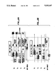
- FIG. 1 is a block diagram illustrating a preferred embodiment of a system fabricated according to the invention.
- FIGS. 2A and 2B are representative wave form diagrams illustrating the operation of the system of FIG. 1.
- FIG. 1 is a block diagram illustrating a preferred embodiment of a system incorporating the invention.
- a pair of transducers 10, 12 are arranged along a flow path and are separated by a constant distance L.
- Transducers 10, 12 may comprise any suitable transducer capable of generating a burst of acoustic waves of a predetermined frequency over a desired repetition rate range in a fluid medium. Since such transducers are well known to those skilled in the art, they will not be further described.
- acoustic waves generated by transducers 10, 12 comprise a burst of about 20 cycles of a 40 khz signal, with the repetition rate of each burst being in the range from around zero to 300 hz.
- any fluid flow along the flow path occurs at a velocity v, and one purpose of the invention is to measure this value.
- fluid flow v is measured by determining the travel time of each burst from transducer 10 to transducer 12 in the parallel direction (left to right in FIG. 1) and from transducer 12 to transducer 10 in the anti-parallel direction (from right to left in FIG. 1).
- the flow path may be any conduit such as a spirometer tube or the like through which fluid can flow at a velocity v.
- Each one of transducers 10, 12 is operated in both a transmit mode and a receive mode. Ideally, under zero flow conditions, each transducer 10, 12 will be operated in the transmit mode simultaneously to create an acoustic burst at each location simultaneously. When there is flow along a given direction (such as the parallel direction illustrated), the transducers 10, 12 are operated in the transmit mode at different times as part of the novel functioning of the invention.
- Each transducer is also operated in a receive mode for a sufficient period of time to detect the acoustic burst flowing along the flow path from the opposite transducer.
- the received acoustic bursts are converted to equivalent electrical signals having the same frequency and phase as the acoustic burst waves received.
- Each transducer 10, 12 is driven in the transmit mode by an associated programmable timer 13, 14 via an associated buffer amplifier 16, 17 and an associated transmit switch 19, 20 operated by a separate transmit enable signal supplied by a microprocessor unit 25.
- Each programmable timer 13, 14 is provided with a high frequency (8 mhz) frequency reference F supplied by a system oscillator 26, preferably a quartz crystal controlled oscillator.
- Each programmable timer 13, 14 is also provided with appropriate control signals from the microprocessor unit 25 via system bus 27.
- Each timer 13, 14 has a dual function: firstly, to generate the 40 khz transmit signals supplied to the associated transducer; and secondly to provide phase reference signals S i and S q used to establish the acoustic burst travel times along the flow path in a manner described below.
- the phase reference signals S i and S q are also 40 khz signals and are arranged in phase quadrature, i.e., reference signal S q is phase displaced from reference signal S i by 90°.
- the output signals generated by transducer 10, 12 in response to received acoustic bursts are coupled via dedicated amplifiers 31, 32 to associated zero crossing detectors 33, 34 in which the received equivalent signals are squared up to produce binary wave trains corresponding to the received signals.
- the output of each zero crossing detector 33, 34 is coupled to an associated pair of phase detectors in the following manner.
- the output signals from zero crossing detector 33, representing the received signals corresponding to the acoustic burst originally transmitted by transducer 12, are coupled as a first input to a pair of phase detectors 36, 37, which in the preferred embodiment are a pair of exclusive OR gates.
- phase detector 36 The other input to phase detector 36 is the zero phase reference signal S i supplied by programmable timer 13; the other input to phase detector 37 is the quadrature reference signal S q from programmable timer 14.
- the output of zero crossing detector 34 representing the received version of the acoustic burst originally generated by transducer 10 is coupled to a first input of a pair of associated phase detectors 38, 39.
- the other input to phase detector 38 is the phase reference signal S i ; while the other input to phase detector 39 is the quadrature phase reference signal S q .
- phase detector 36 is coupled to the gating input of a first digital integrator 41, which is a high speed incrementable counter in the preferred embodiment.
- the sample clock or count input to integrator 41 is the high frequency reference signal generated by oscillator 26.
- a digital integrator 42 has a clock input for receiving the high speed clock signal F and a gating input to receive the output of phase detector 37.
- Digital integrators 43 and 44 are similarly arranged to receive the high speed clock input F and the output from phase detectors 38, 39, respectively.
- Each digital integrator 41-44 is arranged to accumulate counts whenever a phase difference exists between the two inputs to the respective phase detector.
- digital integrator 41 accumulates counts over a comparison period which corresponds to the total phase difference between the phase reference signal S i and the signals received by transducer 10 from transducer 12;
- integrator 42 accumulates a count over a comparison period corresponding to the total phase difference between the quadrature phase reference signal S q and the signals received by transducer 10 from transducer 12;
- digital integrator 43 accumulates a count representative of the total phase difference between the phase reference signal S i and the signals received by transducer 12 from transducer 10;
- integrator 44 accumulates a count representative of the total phase difference between the quadrature phase reference signal S q and the signals received by transducer 12 from transducer 10.
- Integrators 41-44 are under the control of microprocessor unit 25 via bus 27.
- the accumulated results at the end of a comparison period are transferred over bus 27 to the microprocessor unit 25 for computational purposes, and the results are output via bus 27 through a suitable I/O device 29 to any suitable follow-on unit, such as a strip chart recorder, a printer or the like.
- the system of FIG. 1 is operated in such a manner that the travel time of an acoustic wave along the flow path between transducers 10 and 12 is measured in both directions to great accuracy (on the order of 4.0 nanoseconds for a 40 khz wave and a system frequency F of 8 mhz). These travel times in opposite directions are then used to compute values of interest, such as flow velocity, actual speed of sound, flow volume or the like.
- v flow velocity
- L the distance between transducers 10 and 12
- T p the wave travel time in the parallel direction between transducer 10 and transducer 12
- T a the wave travel time between transducer 12 and transducer 10 in the anti-parallel direction.
- speed of sound in the fluid can be calculated according to the following formula: ##EQU2## where c equals the speed of sound in the fluid and the remaining variables have the same significance as noted above.
- FIG. 2A illustrates representative system signals in the case of zero flow along the flow path.
- the signal labelled S a is the acoustic signal generated in the anti-parallel direction
- signal S p is the acoustic signal generated in the parallel flow path direction
- signal S i represents the output from programmable timer 13
- signal S q represents the signal output from programmable timer 14.
- the transmit enable signal which is active over the first half period of a sample period in the preferred embodiment. As can be seen in FIG.
- transducer 10 after the commencement of the sample period designated by the active level of the transmit enable signal, transducer 10 generates a 40 khz burst of acoustic waves S p over a period of time which is less than the duration of the transmit enable signal during the sample period.
- transducer 12 emits a burst of several cycles of acoustic waves Sa over essentially the same period.
- the burst is generated in response to the receipt from the associated programmable timer of the 40 khz drive signal. This signal is generated by the associated timer 13, 14 for a predetermined number of cycles, which in the preferred embodiment is 20 cycles.
- each transducer 10, 12 continues to ring down for a measurable period of time, after which each transducer 10, 12 is ready to receive the acoustic burst travelling through the fluid along the flow path from the opposite transducer.
- the pulses received by the transducers 10, 12 are shown in FIG. 2A to the right of the transmit pulses spaced by a distance equal to the flow path length L divided by the speed of sound c in the fluid.
- the transducers 10, 12 generate the electrical equivalent to the acoustic signals, which have the packet shape illustrated for signals S a and S p . These signals are coupled to the respective phase detectors 36-39 where the phase of each signal is compared with the quadrature phase reference signals S i and S q .
- the zero phase reference (the in-phase reference) is generated by timer 13, while the quadrature reference, (which differs in phase from the in-phase reference by +90°) is generated by timer 14.
- Each received burst packet is phase compared with both phase references over a predetermined number of 40 khz cycles.
- the number of cycles over which the phase comparison is conducted is 16 and these 16 cycles are selected by the microprocessor unit 25 to be centered about the expected central portion of the burst packet.
- the 16 cycles over which the phase comparison is made comprise the 3rd through 18th cycles in the burst packet.
- the in-phase and quadrature digital integrators accumulate counts whenever an out-of-phase condition exists between the two inputs to each phase detector.
- integrator 41 accumulates counts whenever the received burst is out of phase with respect to the in-phase reference signal S i
- integrator 42 accumulates counts whenever the received signal is out of phase with respect to the quadrature phase reference S q . Since the phase comparison is conducted over a predetermined number of cycles, time varying effects are averaged. Thus, for example, if the actual frequency of the 40 khz signal within the burst packet varies at all over the 16 cycle comparison period, such variations will be averaged in the integrators 41, 42. The same is true with respect to the integrators 43, 44 and the signals received by transducer 12.
- the contents of the integrators 41-44 are examined to determine the phase difference between the received signals and the reference signals. Since the received signals are compared with quadrature related phase reference signals, not only the magnitude of the phase difference but also the direction can be determined. Consequently, the result of the examination of the contents of the digital integrators 41-44 by the microprocessor system 25 is a direct measure of the difference in travel time in the parallel and anti-parallel directions. This difference is noted for each sample cycle and changes from cycle to cycle can be measured and accumulated. With the 40 khz drive signals and phase reference signals employed, and a 8 mhz system frequency F, the accuracy of the measurement over 16 cycles is 200 counts per cycle times 16 Or 3200 counts total. The smallest detectable phase change divided by the largest detectable phase change in this system is 1 divided by 3200, which is quite precise.
- One of the significant aspects of the signal processing according to the invention is the manner in which changes in the signal travel time between the transducers 10, 12 are tracked.
- the launch time of the next to be transmitted acoustic burst is changed to compensate for the measured change in phase.
- each sample cycle begins with the same initial conditions: viz., if there is no change in the velocity or speed parameters since the last sample cycle the phase difference between the received signals and the phase reference signals should be zero.
- FIG. 2B illustrates to an exaggerated scale the launch time adjustment after a phase comparison has resulted in a determination that the flow velocity v in the parallel direction has increased between samples.
- the transmit time of the burst from transducer 10 is retarded by an amount substantially equal to the phase difference between the signals received by transducer 12 and the phase references.
- the transmit time of the acoustic burst from transducer 12 is advanced by an amount equal to the phase difference between the signals received by transducer 10 (flowing in the upstream direction) and the phase reference signals. In this manner, the expected arrival time of each acoustic burst at each transducer relative to the phase reference signals and the integration interval is maintained constant.
- the invention provides highly accurate measurement of the travel time of acoustic pulses between two locations in a fluid flow path.
- a maximum of 200 counts per cycle can be accumulated in any of the digital integrators 41-44. Since 16 successive cycles are used as the phase measurement period, a total of 3200 counts is the maximum number which could be accumulated. Consequently, the ratio between the smallest detectable phase change and the largest detectable phase change is 1 divided by 3200.
- the corresponding period is 25 microseconds, and the time between successive 8 mhz clock pulses is 125 nanoseconds, which is the lower limit on resolution of the phase difference magnitude per cycle of drive signal.
- the programmable timers 13, 14, which are used to derive the drive signals from the relatively high frequency system clock 26, can also be used to generate the phase reference signals, which saves hardware costs. Also, since the entire system is under control of the microprocessor unit 25, computational changes and frequency changes can be relatively easy to implement.
- the first inequality covers the range of phase from -90° to +90°; the intermediate inequality covers the phase range from +90° to +180°; and the last inequality covers the range from -90° to -180°. It should be understood that this algorithm is by way of example only, and that other algorithms may be employed, as desired.
Landscapes
- Physics & Mathematics (AREA)
- General Physics & Mathematics (AREA)
- Engineering & Computer Science (AREA)
- Radar, Positioning & Navigation (AREA)
- Remote Sensing (AREA)
- Electromagnetism (AREA)
- Fluid Mechanics (AREA)
- Acoustics & Sound (AREA)
- Computer Networks & Wireless Communication (AREA)
- Measuring Volume Flow (AREA)
- Measurement Of Mechanical Vibrations Or Ultrasonic Waves (AREA)
Abstract
Description
Claims (24)
Priority Applications (5)
| Application Number | Priority Date | Filing Date | Title |
|---|---|---|---|
| US07/478,101 US5035147A (en) | 1990-02-09 | 1990-02-09 | Method and system for digital measurement of acoustic burst travel time in a fluid medium |
| DE69110697T DE69110697T2 (en) | 1990-02-09 | 1991-01-31 | Method and system for digital time measurement of acoustic impulses in a liquid medium. |
| EP91300755A EP0441531B1 (en) | 1990-02-09 | 1991-01-31 | Method and system for digital measurement of acoustic burst travel time in a fluid medium |
| CA002035773A CA2035773C (en) | 1990-02-09 | 1991-02-06 | Method and system for digital measurement of acoustic burst travel time in a fluid medium |
| JP3039060A JP3023569B2 (en) | 1990-02-09 | 1991-02-12 | Method and apparatus for digitally measuring acoustic burst transit time in a fluid medium |
Applications Claiming Priority (1)
| Application Number | Priority Date | Filing Date | Title |
|---|---|---|---|
| US07/478,101 US5035147A (en) | 1990-02-09 | 1990-02-09 | Method and system for digital measurement of acoustic burst travel time in a fluid medium |
Publications (1)
| Publication Number | Publication Date |
|---|---|
| US5035147A true US5035147A (en) | 1991-07-30 |
Family
ID=23898520
Family Applications (1)
| Application Number | Title | Priority Date | Filing Date |
|---|---|---|---|
| US07/478,101 Expired - Lifetime US5035147A (en) | 1990-02-09 | 1990-02-09 | Method and system for digital measurement of acoustic burst travel time in a fluid medium |
Country Status (5)
| Country | Link |
|---|---|
| US (1) | US5035147A (en) |
| EP (1) | EP0441531B1 (en) |
| JP (1) | JP3023569B2 (en) |
| CA (1) | CA2035773C (en) |
| DE (1) | DE69110697T2 (en) |
Cited By (30)
| Publication number | Priority date | Publication date | Assignee | Title |
|---|---|---|---|---|
| US5325726A (en) * | 1991-05-05 | 1994-07-05 | Prof. Dr. Ing. Gunther Krieg | Method and device for measuring volume flows in liquids and gases |
| US5373736A (en) * | 1992-03-11 | 1994-12-20 | Woods Hole Oceanographic Institute | Acoustic current meter |
| US5419326A (en) * | 1992-06-03 | 1995-05-30 | Ndd Medizintechnik Gmbh | Spirometer, more particularly an ultrasonic spirometer |
| US5461931A (en) * | 1991-09-16 | 1995-10-31 | British Gas Plc | Measurement system |
| US5464039A (en) * | 1993-04-27 | 1995-11-07 | Nuovopignone - Industrie Meccaniche E Fonderia S.P.A. | Fluid flowmeter-controller |
| US5583301A (en) * | 1994-11-09 | 1996-12-10 | National Environmental Products Ltd., Inc. | Ultrasound air velocity detector for HVAC ducts and method therefor |
| US5639971A (en) * | 1996-10-04 | 1997-06-17 | Dieterich Technology Holding Corp. | Method and apparatus for detecting a signal |
| US5748504A (en) * | 1996-06-12 | 1998-05-05 | Welch Allyn, Inc. | Calibration method for use with ultrasonic flowmeters |
| US5747749A (en) * | 1996-12-11 | 1998-05-05 | Mobil Oil Corporation | Acoustic logging to identify oil flow rate |
| US5753824A (en) * | 1996-06-12 | 1998-05-19 | Welch Allyn, Inc. | Sampling method and apparatus for use with ultrasonic flowmeters |
| US5777238A (en) * | 1996-06-12 | 1998-07-07 | Welch Allyn, Inc. | Driver-receiver apparatus for use with ultrasonic flowmeters |
| US5777278A (en) * | 1996-12-11 | 1998-07-07 | Mobil Oil Corporation | Multi-phase fluid flow measurement |
| US5804739A (en) * | 1995-06-22 | 1998-09-08 | Erwin Sick Gmbh Optik-Elektronik | Method and circuit arrangement for the measurement of flow speed by means of acoustical transit time differences |
| US5814737A (en) * | 1996-10-04 | 1998-09-29 | Dieterich Technology Holding Corp. | Apparatus and method of detecting an ultrasonic signal |
| US5831175A (en) * | 1996-06-12 | 1998-11-03 | Welch Allyn, Inc. | Method and apparatus for correcting temperature variations in ultrasonic flowmeters |
| US5905207A (en) * | 1996-04-04 | 1999-05-18 | Georg Fischer Rohrleitungssysteme Ag | Process for measuring the flow rate of a fluid |
| US5929342A (en) * | 1996-04-16 | 1999-07-27 | Mobil Oil Corporation | Method for monitoring three phrase fluid flow in tubulars |
| WO1999056135A1 (en) * | 1998-04-24 | 1999-11-04 | Commonwealth Scientific And Industrial Research Organisation | A liquid flow meter |
| US6094987A (en) * | 1998-06-10 | 2000-08-01 | Fuji Ultrasonic Engineering Co. Ltd. | Method and apparatus for ultrasonic wave measurement |
| US6119070A (en) * | 1995-09-25 | 2000-09-12 | Schlumberger Industries, S.A. | Method for acoustically measuring a fluid flow rate |
| US6202494B1 (en) * | 1997-05-28 | 2001-03-20 | Degussa-Huls Aktiengesellschaft | Process and apparatus for measuring density and mass flow |
| US6305233B1 (en) * | 1995-10-19 | 2001-10-23 | Commonwealth Scientific And Industrial Research Organisation | Digital speed determination in ultrasonic flow measurements |
| US6435037B1 (en) | 2000-01-06 | 2002-08-20 | Data Sciences International, Inc. | Multiplexed phase detector |
| WO2002086666A2 (en) * | 2001-04-20 | 2002-10-31 | Ads Corporation | Flow transport analysis method and system |
| US6539316B1 (en) | 2000-01-06 | 2003-03-25 | Data Sciences International, Inc. | Phase detector |
| US6595071B1 (en) | 2000-01-06 | 2003-07-22 | Transoma Medical, Inc. | Estimation of error angle in ultrasound flow measurement |
| DE19934212B4 (en) * | 1998-07-24 | 2004-09-02 | Institut Français du Pétrole, Rueil-Malmaison | Method and device for measuring the flow rate of a fluid stream |
| US20070186680A1 (en) * | 2004-05-22 | 2007-08-16 | Tobias Lang | Determination of a reception time of an ultrasonic signal by means of pulse shape detection |
| US9194787B2 (en) | 2012-11-05 | 2015-11-24 | Exxonmobil Upstream Research Company | Testing apparatus for simulating stratified or dispersed flow |
| US20160370214A1 (en) * | 2015-06-19 | 2016-12-22 | Accutron Instruments Inc. | Method and system for ultrasonic airflow measurements |
Families Citing this family (5)
| Publication number | Priority date | Publication date | Assignee | Title |
|---|---|---|---|---|
| GB2282223A (en) * | 1993-09-22 | 1995-03-29 | Cyril Ward Nugent | Flow measuring apparatus |
| WO1995018958A1 (en) * | 1994-01-10 | 1995-07-13 | Siemens Aktiengesellschaft | Process for finding the volume flow rate of a gas in a measuring tube |
| DE97610055T1 (en) * | 1996-12-05 | 2007-08-02 | Kamstrup A/S | Flow meter, method for measuring a flow and method for operating a flow meter |
| JP4886120B2 (en) * | 2001-05-16 | 2012-02-29 | 東京計器株式会社 | Ultrasonic current meter |
| DE10236563B4 (en) * | 2002-08-08 | 2006-07-20 | Hydrometer Gmbh | Transmitting and receiving circuit for an ultrasonic flowmeter |
Citations (6)
| Publication number | Priority date | Publication date | Assignee | Title |
|---|---|---|---|---|
| US3738169A (en) * | 1970-02-17 | 1973-06-12 | Thomson Csf | Ultrasonic flowmeters |
| US3901078A (en) * | 1973-09-07 | 1975-08-26 | Westinghouse Electric Corp | Ultrasonic system for fluid flow measurement |
| US4162630A (en) * | 1976-09-20 | 1979-07-31 | University Of Utah | Measurement and reconstruction of three-dimensional fluid flow |
| US4384491A (en) * | 1981-01-22 | 1983-05-24 | Bestobell Sparling Ltd. | Analog ultrasonic flowmeter |
| US4452090A (en) * | 1982-05-17 | 1984-06-05 | Airco, Inc. | Ultrasonic flowmeter |
| US4611496A (en) * | 1983-07-27 | 1986-09-16 | Tokyo Keiki Co., Ltd. | Ultrasonic flow meter |
Family Cites Families (1)
| Publication number | Priority date | Publication date | Assignee | Title |
|---|---|---|---|---|
| GB8430217D0 (en) * | 1984-11-30 | 1985-01-09 | Redding R J | Electronic gas meter |
-
1990
- 1990-02-09 US US07/478,101 patent/US5035147A/en not_active Expired - Lifetime
-
1991
- 1991-01-31 DE DE69110697T patent/DE69110697T2/en not_active Expired - Fee Related
- 1991-01-31 EP EP91300755A patent/EP0441531B1/en not_active Expired - Lifetime
- 1991-02-06 CA CA002035773A patent/CA2035773C/en not_active Expired - Fee Related
- 1991-02-12 JP JP3039060A patent/JP3023569B2/en not_active Expired - Fee Related
Patent Citations (6)
| Publication number | Priority date | Publication date | Assignee | Title |
|---|---|---|---|---|
| US3738169A (en) * | 1970-02-17 | 1973-06-12 | Thomson Csf | Ultrasonic flowmeters |
| US3901078A (en) * | 1973-09-07 | 1975-08-26 | Westinghouse Electric Corp | Ultrasonic system for fluid flow measurement |
| US4162630A (en) * | 1976-09-20 | 1979-07-31 | University Of Utah | Measurement and reconstruction of three-dimensional fluid flow |
| US4384491A (en) * | 1981-01-22 | 1983-05-24 | Bestobell Sparling Ltd. | Analog ultrasonic flowmeter |
| US4452090A (en) * | 1982-05-17 | 1984-06-05 | Airco, Inc. | Ultrasonic flowmeter |
| US4611496A (en) * | 1983-07-27 | 1986-09-16 | Tokyo Keiki Co., Ltd. | Ultrasonic flow meter |
Non-Patent Citations (2)
| Title |
|---|
| "Ultrasonic Measurements for Process Control", Theory, Techniques, Applications, Lynnworth, Academic Press, Inc. Harcourt Brace Jovanovich, Publishers, pp. 17 and 19. |
| Ultrasonic Measurements for Process Control , Theory, Techniques, Applications, Lynnworth, Academic Press, Inc. Harcourt Brace Jovanovich, Publishers, pp. 17 and 19. * |
Cited By (37)
| Publication number | Priority date | Publication date | Assignee | Title |
|---|---|---|---|---|
| US5325726A (en) * | 1991-05-05 | 1994-07-05 | Prof. Dr. Ing. Gunther Krieg | Method and device for measuring volume flows in liquids and gases |
| US5461931A (en) * | 1991-09-16 | 1995-10-31 | British Gas Plc | Measurement system |
| US5373736A (en) * | 1992-03-11 | 1994-12-20 | Woods Hole Oceanographic Institute | Acoustic current meter |
| US5419326A (en) * | 1992-06-03 | 1995-05-30 | Ndd Medizintechnik Gmbh | Spirometer, more particularly an ultrasonic spirometer |
| US5464039A (en) * | 1993-04-27 | 1995-11-07 | Nuovopignone - Industrie Meccaniche E Fonderia S.P.A. | Fluid flowmeter-controller |
| US5583301A (en) * | 1994-11-09 | 1996-12-10 | National Environmental Products Ltd., Inc. | Ultrasound air velocity detector for HVAC ducts and method therefor |
| US5804739A (en) * | 1995-06-22 | 1998-09-08 | Erwin Sick Gmbh Optik-Elektronik | Method and circuit arrangement for the measurement of flow speed by means of acoustical transit time differences |
| US6119070A (en) * | 1995-09-25 | 2000-09-12 | Schlumberger Industries, S.A. | Method for acoustically measuring a fluid flow rate |
| US6305233B1 (en) * | 1995-10-19 | 2001-10-23 | Commonwealth Scientific And Industrial Research Organisation | Digital speed determination in ultrasonic flow measurements |
| US5905207A (en) * | 1996-04-04 | 1999-05-18 | Georg Fischer Rohrleitungssysteme Ag | Process for measuring the flow rate of a fluid |
| US5929342A (en) * | 1996-04-16 | 1999-07-27 | Mobil Oil Corporation | Method for monitoring three phrase fluid flow in tubulars |
| US5777238A (en) * | 1996-06-12 | 1998-07-07 | Welch Allyn, Inc. | Driver-receiver apparatus for use with ultrasonic flowmeters |
| US5753824A (en) * | 1996-06-12 | 1998-05-19 | Welch Allyn, Inc. | Sampling method and apparatus for use with ultrasonic flowmeters |
| US5831175A (en) * | 1996-06-12 | 1998-11-03 | Welch Allyn, Inc. | Method and apparatus for correcting temperature variations in ultrasonic flowmeters |
| US5748504A (en) * | 1996-06-12 | 1998-05-05 | Welch Allyn, Inc. | Calibration method for use with ultrasonic flowmeters |
| US5814737A (en) * | 1996-10-04 | 1998-09-29 | Dieterich Technology Holding Corp. | Apparatus and method of detecting an ultrasonic signal |
| US5639971A (en) * | 1996-10-04 | 1997-06-17 | Dieterich Technology Holding Corp. | Method and apparatus for detecting a signal |
| US5777278A (en) * | 1996-12-11 | 1998-07-07 | Mobil Oil Corporation | Multi-phase fluid flow measurement |
| US5747749A (en) * | 1996-12-11 | 1998-05-05 | Mobil Oil Corporation | Acoustic logging to identify oil flow rate |
| US6202494B1 (en) * | 1997-05-28 | 2001-03-20 | Degussa-Huls Aktiengesellschaft | Process and apparatus for measuring density and mass flow |
| US6508135B1 (en) * | 1998-04-24 | 2003-01-21 | Commonwealth Scientific And Industrial Research Organisation | Liquid flow meter |
| WO1999056135A1 (en) * | 1998-04-24 | 1999-11-04 | Commonwealth Scientific And Industrial Research Organisation | A liquid flow meter |
| US6094987A (en) * | 1998-06-10 | 2000-08-01 | Fuji Ultrasonic Engineering Co. Ltd. | Method and apparatus for ultrasonic wave measurement |
| DE19934212B4 (en) * | 1998-07-24 | 2004-09-02 | Institut Français du Pétrole, Rueil-Malmaison | Method and device for measuring the flow rate of a fluid stream |
| US6595071B1 (en) | 2000-01-06 | 2003-07-22 | Transoma Medical, Inc. | Estimation of error angle in ultrasound flow measurement |
| US6539316B1 (en) | 2000-01-06 | 2003-03-25 | Data Sciences International, Inc. | Phase detector |
| US6435037B1 (en) | 2000-01-06 | 2002-08-20 | Data Sciences International, Inc. | Multiplexed phase detector |
| WO2002086666A2 (en) * | 2001-04-20 | 2002-10-31 | Ads Corporation | Flow transport analysis method and system |
| WO2002086666A3 (en) * | 2001-04-20 | 2003-11-06 | Ads Corp | Flow transport analysis method and system |
| US6757623B2 (en) * | 2001-04-20 | 2004-06-29 | Ads Corporation | Flow transport analysis method and system |
| US20060116829A1 (en) * | 2001-04-20 | 2006-06-01 | Schutzbach James S | Flow transport analysis method and system |
| US7424374B2 (en) | 2001-04-20 | 2008-09-09 | Ads, Llc | Flow transport analysis method and system |
| US20070186680A1 (en) * | 2004-05-22 | 2007-08-16 | Tobias Lang | Determination of a reception time of an ultrasonic signal by means of pulse shape detection |
| US8744785B2 (en) * | 2004-05-22 | 2014-06-03 | Robert Bosch Gmbh | Determination of a reception time of an ultrasonic signal by means of pulse shape detection |
| US9194787B2 (en) | 2012-11-05 | 2015-11-24 | Exxonmobil Upstream Research Company | Testing apparatus for simulating stratified or dispersed flow |
| US20160370214A1 (en) * | 2015-06-19 | 2016-12-22 | Accutron Instruments Inc. | Method and system for ultrasonic airflow measurements |
| US10041967B2 (en) * | 2015-06-19 | 2018-08-07 | Accutron Instruments Inc. | Method and system for ultrasonic airflow measurements |
Also Published As
| Publication number | Publication date |
|---|---|
| DE69110697T2 (en) | 1996-01-11 |
| CA2035773A1 (en) | 1991-08-10 |
| EP0441531A2 (en) | 1991-08-14 |
| EP0441531B1 (en) | 1995-06-28 |
| CA2035773C (en) | 2000-11-14 |
| EP0441531A3 (en) | 1992-04-15 |
| JPH06180324A (en) | 1994-06-28 |
| DE69110697D1 (en) | 1995-08-03 |
| JP3023569B2 (en) | 2000-03-21 |
Similar Documents
| Publication | Publication Date | Title |
|---|---|---|
| US5035147A (en) | Method and system for digital measurement of acoustic burst travel time in a fluid medium | |
| CA1157935A (en) | Ultrasonic flowmeter | |
| US4480485A (en) | Acoustic flowmeter with envelope midpoint tracking | |
| US4015470A (en) | Flow measuring method and apparatus | |
| US5796009A (en) | Method for measuring in a fluid with the aid of sing-around technique | |
| US4011755A (en) | Acoustic flowmeter | |
| US4019038A (en) | Correlators | |
| US4003256A (en) | Acoustic oscillator fluid velocity measuring device | |
| CA2233974A1 (en) | Digital speed determination in ultrasonic flow measurements | |
| US4265125A (en) | Flowmeter method and apparatus | |
| CA1216656A (en) | Method and apparatus for measuring fluid flow | |
| JPS5952367B2 (en) | flow measuring device | |
| US5818735A (en) | Method and system for high resolution time-of-flight measurements | |
| US4011753A (en) | Method and device for measuring the flow velocity of media by means of ultrasound | |
| US4616510A (en) | Fluid velocity measuring method and apparatus | |
| US6422094B1 (en) | Method for determining the flow rate and/or the molecular mass of liquid or gaseous media | |
| US3678731A (en) | Apparatus for measuring the flow velocity of fluids | |
| US4603589A (en) | Ultrasonic flowmeter | |
| US4391150A (en) | Electro-acoustic flowmeter | |
| US3623363A (en) | Ultrasonic flowmeter | |
| GB2046442A (en) | Ultrasonic flow meter | |
| US4203322A (en) | Apparatus for the ultrasonic measurement of the flow velocity of fluent media | |
| JPH11304559A (en) | Flow rate measuring apparatus | |
| JP3422100B2 (en) | Flow measurement device | |
| EP0250660B1 (en) | Fluid velocity measuring method and apparatus |
Legal Events
| Date | Code | Title | Description |
|---|---|---|---|
| AS | Assignment |
Owner name: CURTIN MATHESON SCIENTIFIC, INC, TEXAS Free format text: ASSIGNMENT OF ASSIGNORS INTEREST.;ASSIGNOR:WOODWARD, WILLIAM S.;REEL/FRAME:005229/0836 Effective date: 19900207 |
|
| STCF | Information on status: patent grant |
Free format text: PATENTED CASE |
|
| FEPP | Fee payment procedure |
Free format text: PAYOR NUMBER ASSIGNED (ORIGINAL EVENT CODE: ASPN); ENTITY STATUS OF PATENT OWNER: LARGE ENTITY |
|
| FPAY | Fee payment |
Year of fee payment: 4 |
|
| AS | Assignment |
Owner name: J&W SCIENTIFIC INCORPORATED, CALIFORNIA Free format text: ASSIGNMENT OF ASSIGNORS INTEREST;ASSIGNOR:FISIONS U.S. INC.;REEL/FRAME:007744/0445 Effective date: 19951013 Owner name: FISONS U.S. INC., TEXAS Free format text: ASSIGNMENT OF ASSIGNORS INTEREST;ASSIGNOR:CURTIN MATHESON SCIENTIFIC, INC.;REEL/FRAME:007744/0441 Effective date: 19951013 |
|
| FEPP | Fee payment procedure |
Free format text: PAT HOLDER CLAIMS SMALL ENTITY STATUS - SMALL BUSINESS (ORIGINAL EVENT CODE: SM02); ENTITY STATUS OF PATENT OWNER: LARGE ENTITY |
|
| FPAY | Fee payment |
Year of fee payment: 8 |
|
| AS | Assignment |
Owner name: IBJS, NEW YORK Free format text: SECURITY AGREEMENT;ASSIGNOR:J&W SCIENTIFIC INCORPORATED;REEL/FRAME:009479/0199 Effective date: 19980811 |
|
| AS | Assignment |
Owner name: AGILENT TECHNOLOGIES, INC., CALIFORNIA Free format text: ASSIGNMENT OF ASSIGNORS INTEREST;ASSIGNOR:J&W SCIENTIFIC INCORPORATED;REEL/FRAME:012036/0164 Effective date: 20010924 |
|
| FEPP | Fee payment procedure |
Free format text: PAT HOLDER NO LONGER CLAIMS SMALL ENTITY STATUS, ENTITY STATUS SET TO UNDISCOUNTED (ORIGINAL EVENT CODE: STOL); ENTITY STATUS OF PATENT OWNER: LARGE ENTITY |
|
| FPAY | Fee payment |
Year of fee payment: 12 |
|
| AS | Assignment |
Owner name: J&W SCIENTIFIC INCORPORATED, CALIFORNIA Free format text: RELEASE OF SECURITY AGREEMENT AND MORTGAGE IN US PATENTS;ASSIGNOR:IBJS;REEL/FRAME:014532/0113 Effective date: 20020717 |