US5033889A - Open loop carriage control for dot-matrix printer using tables - Google Patents
Open loop carriage control for dot-matrix printer using tables Download PDFInfo
- Publication number
- US5033889A US5033889A US07/326,142 US32614289A US5033889A US 5033889 A US5033889 A US 5033889A US 32614289 A US32614289 A US 32614289A US 5033889 A US5033889 A US 5033889A
- Authority
- US
- United States
- Prior art keywords
- printhead
- wires
- firing
- paper
- carriage
- Prior art date
- Legal status (The legal status is an assumption and is not a legal conclusion. Google has not performed a legal analysis and makes no representation as to the accuracy of the status listed.)
- Expired - Lifetime
Links
- 239000011159 matrix material Substances 0.000 title claims abstract description 16
- 238000010304 firing Methods 0.000 claims abstract description 38
- 238000000034 method Methods 0.000 claims abstract description 20
- 230000008859 change Effects 0.000 claims description 10
- 230000001133 acceleration Effects 0.000 claims description 9
- 230000004044 response Effects 0.000 claims description 8
- 230000003247 decreasing effect Effects 0.000 claims description 4
- 230000000694 effects Effects 0.000 claims 1
- 238000010586 diagram Methods 0.000 description 7
- 239000003086 colorant Substances 0.000 description 3
- 230000007246 mechanism Effects 0.000 description 3
- 230000008569 process Effects 0.000 description 3
- 210000005069 ears Anatomy 0.000 description 2
- 230000003287 optical effect Effects 0.000 description 2
- 238000004804 winding Methods 0.000 description 2
- 101001022148 Homo sapiens Furin Proteins 0.000 description 1
- 101000701936 Homo sapiens Signal peptidase complex subunit 1 Proteins 0.000 description 1
- 102100030313 Signal peptidase complex subunit 1 Human genes 0.000 description 1
- 238000000819 phase cycle Methods 0.000 description 1
- 230000000007 visual effect Effects 0.000 description 1
Images


Classifications
-
- B—PERFORMING OPERATIONS; TRANSPORTING
- B41—PRINTING; LINING MACHINES; TYPEWRITERS; STAMPS
- B41J—TYPEWRITERS; SELECTIVE PRINTING MECHANISMS, i.e. MECHANISMS PRINTING OTHERWISE THAN FROM A FORME; CORRECTION OF TYPOGRAPHICAL ERRORS
- B41J19/00—Character- or line-spacing mechanisms
- B41J19/18—Character-spacing or back-spacing mechanisms; Carriage return or release devices therefor
- B41J19/20—Positive-feed character-spacing mechanisms
- B41J19/202—Drive control means for carriage movement
-
- Y—GENERAL TAGGING OF NEW TECHNOLOGICAL DEVELOPMENTS; GENERAL TAGGING OF CROSS-SECTIONAL TECHNOLOGIES SPANNING OVER SEVERAL SECTIONS OF THE IPC; TECHNICAL SUBJECTS COVERED BY FORMER USPC CROSS-REFERENCE ART COLLECTIONS [XRACs] AND DIGESTS
- Y10—TECHNICAL SUBJECTS COVERED BY FORMER USPC
- Y10S—TECHNICAL SUBJECTS COVERED BY FORMER USPC CROSS-REFERENCE ART COLLECTIONS [XRACs] AND DIGESTS
- Y10S400/00—Typewriting machines
- Y10S400/903—Stepping-motor drive for carriage feed
Definitions
- the firing of the wires to register corresponding marks on paper is usually done on the fly, in other words, while the printhead is moving.
- the printhead therefore, can completely traverse the width of the paper and print the desired dot pattern at each of a plurality of evenly spaced positions as it traverses the paper without ever stopping.
- the printhead is usually subjected to selective energization at regular time intervals in order to fire the wires and thus register dots at the selected positions on the paper. It has been the practice to accelerate the carriage before printing is begun and to stop printing before the carriage is decelerated at the end of its travel. Such practices have been necessary in order not to introduce decreased spacing between consecutive printing positions in the accelerating or decelerating areas of the traverse.
- the width of the chart paper In industrial type recorders the width of the chart paper must be kept to a maximum in order to have a maximum resolution in the record. Since the width of the recorder case is limited to the standard rack dimensions typical for industrial mounting, the maximum chart width which is usable for recording is determined in part by the extent of the accelerating and decelerating regions at the beginning and end, respectively, of each traverse unless a means can be found to print in those regions.
- a method for operating a dot-matrix printer of the type which steps the printhead carriage continuously in traverse of the paper on which printing is desired which method includes the steps of: firing the wires for registration at the present position of the carriage and then stepping the carriage by energizing in the appropriate phase the stepper motor driving the carriage.
- the time period for energization is obtained from a table which lists times determined previously as those required to complete the particular step involved when the carriage is in the accelerating region of its traverse or those useful to brake the carriage when it is in the decelerating region of its traverse. These times decrease as the carriage accelerates from a stop to a fixed time during the remainder of the carriage traverse until deceleration is required at which point the times increase as the carriage is decelerated to a stop.
- FIG. 1 shows the manner in which FIGS. 1A and 1B can be juxtaposed in order to provide an example of a strip chart recorder to which the present invention can be applied.
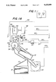
- FIG. 1A is a side view, partially in cross section, of a recorder which can be used in carrying out the invention.
- FIG. 1B is a block diagram of a circuit for the recorder of FIG. 1A which can be used to carry out the invention.
- FIG. 2 is a top elevation of a portion of the recorder of FIG. 1A, taken along line 2--2, showing the transport or drive system for the printhead carriage.
- FIG. 3 is a series of diagrams showing the polarity in which the stepper motor fields are energized for the various phases which may be used to drive the motor.
- FIG. 4 is a time vs. position characteristic for a typical stepper motor such as may be used to drive the printhead carriage in this invention.
- FIG. 5 is a graphical representation of the velocity vs. time characteristic of the carriage drive system as the carriage is driven in a complete traverse of the paper to be printed on.
- FIG. 6 shows how the time spacing between the wire firing signals changes as the carriage accelerates and decelerates during a single traverse.
- FIG. 7 is a timing diagram showing the duration of the first four phases of energization of the carriage drive motor as the carriage is accelerated from a stop.
- FIG. 8 is a timing diagram showing the timing of the pulses which fire the wires of the dot-matrix printhead as the carriage is accelerated from a stop by the timing of the different phases shown in FIG. 7.
- FIG. 9 is a logic diagram showing one series of steps for the process carried out by the invention.
- a recorder is shown having fanfold chart paper 10, of the type which has sprocket holes in its edges to accommodate driving sprockets.
- the chart 10 is shown being fed from a supply tray 12, located toward the back of the recorder, over a cylindrical paper drive roll or platen 14, located near the top front of the recorder.
- the drive roll is shown as having drive sprockets, such as 16, located around its periphery at each of its ends for engaging the sprocket holes.
- the chart is fed from the drive roll into a collection tray 18, located below the drive roll, as the drive roll is driven by the chart drive motor 20.
- This motor is preferably a stepping motor so that the chart is driven in discrete steps in order that it may be accurately positioned at certain times in the recording process so as to locate each individual recorded point along the length of the chart at a position indicative of the time when that point was sampled.
- the stepper motor drives the chart through a belt 22 which is desirably a reinforced rubber timing-tooth belt that has zero backlash in both directions in order to provide a precise positioning of the drive roll.
- a fixed shaft 24 supports the drive roll in a frame 30 through bearings in each end of the roll so that the roll may rotate on the shaft.
- a timing belt pulley 32 is fitted to the drive roll for driving by the belt 22.
- the other end of the drive belt is engaged by the timing belt drive pulley 34.
- Both the driven pulley 32 and the drive pulley 34 have teeth spaced to match the teeth of the timing belt 22 so that the desired positive positioning of the paper drive roll can be accomplished in steps of suitable size.
- the roller 36 is a V-grooved roller in that its periphery has a V-groove for receiving the drive sprockets, such as 16, in order that the edges of the roller 36 will maintain the paper in sprocket engagement.
- the record is impressed on the chart 10 by a printing mechanism 40, which consists of an impact type printhead such as dot-matrix printhead 42 and a carriage 44 for supporting the printhead and carrying it across the chart on a pair of horizontal rails 46 so that the printhead will traverse the full width of the chart 10 in response to the stepping of the carriage positioning motor 48.
- the motor 48 which is a stepping motor, is coupled to the carriage of the printing mechanism by a tensioned drive cable 51.
- the carriage drive is accomplished through a capstan 50 mounted on the shaft 52 of the carriage drive motor.
- the printhead is of the type utilized in dot matrix printers in that it uses a number of wires which are selectively fired in response to electrical signals to cause the wires to impact on the printer ribbon 56b to thereby impress a "dot" on the chart beneath the printer ribbon for each of the wires fired.
- the wires in the print head may be 8 in number and spaced along a line which runs along the length of the chart and is therefore along the time axis of the chart. This spacing can be such that the wires are 1/72 inch apart, which corresponds to one point of type.
- the carriage positioning motor may advantageously be a stepping motor arranged to selectively position the carriage 44 across the chart in steps of 1/72 inch in response to electrical carriage drive signals received from line 54. As shown in FIG. 1A, the wires contained in the print head are fired selectively by print drive signals received from line 62.
- the ribbon cartridge 56 which is suspended from a pivot such as 56a at each end, contains a supply of ribbon, which is recirculated over the chart by the rotation of ribbon motor 58 in response to signals received from line 60.
- the ribbon may be a multicolor ribbon so that it can print different types of data in different colors.
- there are four different color bands on the ribbon To access these bands the ribbon is shifted laterally by a stepping motor 55 which is mounted on the printhead carriage 44 and which positions the ribbon by positioning a guide through which the ribbon runs so that the guide is moved through four different positions as the cartridge pivots to accommodate the guide movement.
- the guide is moved by means of a lead screw drive (not shown) which is stepped by motor 55 in response to signals received on line 57.
- the printhead carriage is caused to traverse the chart four times, once for each position of the ribbon in order to record all of the data which is to be printed in any one color in a single traverse of the carriage so as to minimize the ribbon positioning movement required.
- the top front portion of the recorder contains a dot matrix graphic display 64 which receives its input from line 65. That input is such that the display can provide a scale with a pointer to indicate the value of certain inputs, which may or may not be recorded.
- the display spans the entire width of the chart to provide a visual indication of the values of certain points and to provide a calibration for interpreting the chart record from a distance.
- FIG. 1B shows a block diagram of the electrical circuits of the recorder of FIG. 1A.
- Those circuits include a digital computer circuit 69 for operating the recorder and means for providing inputs to the recorder.
- the heart of the digital computer circuit is, of course, the central processing unit (CPU) 70, which can be a 32016, 16 bit processor.
- CPU central processing unit
- This processor handles the measuring of the inputs which are obtained from the input bus 72 which, in turn, derives its input from the various primary measuring elements associated with the inputs to the input cards 74.
- Each input card may be designed to receive on its input terminals the signals representing a number of the points to be recorded. These signals may typically be voltages from thermocouples, the resistance of a resistance thermometer, pulse input signals, etc.
- the central processor also is coupled to the display drive circuit 76 which provides on line 65 the signals to drive the display 64.
- An operators keyboard 78 and a programmers keyboard 80 are also connected to the CPU by way of the keyboard interface circuits, shown as block 82, in order to provide manual input to the computer.
- the processing which is carried out by the CPU is done in conjunction with the system memory 84 which is coupled to the CPU by the address bus 86 and the system data bus 88. Also coupled to the CPU is another processor 90, a 64180 processor, which is the printer processor and serves to operate a ribbon driver 92 to control ribbon advance, a print driver 94 to control the firing of the print wires, a carriage driver 96 to control carriage position, a color changer 97 to control which color band on the ribbon is positioned under the printhead, and a chart driver 98 to control chart positioning, both forward and backward, in response to signal supplied on line 100.
- a 64180 processor which is the printer processor and serves to operate a ribbon driver 92 to control ribbon advance, a print driver 94 to control the firing of the print wires, a carriage driver 96 to control carriage position, a color changer 97 to control which color band on the ribbon is positioned under the printhead, and a chart driver 98 to control chart positioning, both forward and backward, in response to signal supplied on line 100.
- FIG. 2 shows a top view of the recorder, taken along line 2--2 of FIG. 1A, to illustrate the path of the cable 51, which is attached to carriage 44 to move it along the rails 46 one step at a time.
- the idler pulleys 49a-49c are used to determine the cable path in cooperation with the tensioning pulley 53 which is mounted on a pivoted lever 81.
- Lever 81 is mounted on pivot 83 which is attached to the frame 30 by bracket 85.
- the lever 81 is biased by spring 87 in a direction to tension the cable 51 in order to minimize any slack in the cable while the carriage 44 is driven by the capstan 50.
- An optical "home” sensor 89 detects when the tab 91 on carriage 44 is positioned between the extended ears 93 of the sensor so as to interrupt the light beam projected between those ears. When the light beam is interrupted the computer will know that the carriage 44 is in its home position.
- the stepper motor In order to drive the printhead carriage so it traverses the chart paper 10, the stepper motor is energized sequentially with different phases so that it repeatedly steps to its next position until the chart has been traversed.
- the stepper motor 48 is of a type illustrated in FIG. 3, where four field windings are illustrated with the associated field polarities produced by 8 different phases of energization shown as phases A-H.
- a rotating field will, of course, step the armature with its fixed magnetic poles in one direction or the other depending on the direction of the field rotation. Each change in phase will correspond to a single step of the motor and hence a step to the next printing position for the carriage.
- phase sequence for the motor 48 is B-D-F-H, which is known as “full drive” and gives the most torque.
- a sequence is A-C-E-G, which is known as “wave drive” and gives less power than does “full drive”.
- a third sequence is A-B-C-D-E-F-G, which is known as "half step” and gives twice the resolution of the other sequences.
- stepping motors of the type shown in FIG. 3 have a time vs. position characteristic of the shape shown in FIG. 4, which shows actual values for the position of the carriage at times up to 0.05 seconds.
- the carriage velocity increases with time until the carriage gets up to the desired stepping rate after which the carriage can be moved at a constant velocity. It will, of course, be evident from FIG. 4 that, if the printhead is fired at equal time intervals during acceleration of the carriage, the positions at which registration will be made on the chart will not be evenly spaced. Therefore, it is necessary to either wait until the printhead gets up to its desired speed or find another way of printing evenly spaced marks.
- the deceleration region at the end of the carriage traverse presents a similar problem, as is shown in FIG. 5, where velocity is plotted against time for a full traverse.
- the present invention varies the timing of the individual steps, that is, the time period during which the carriage drive motor is energized in the particular phase associated with each step.
- the time between the consecutive firings of the wires, at the end of each step will vary during the acceleration of the carriage.
- the wire firing signals on line 62 are provided at shorter and shorter intervals as the carriage accelerates until the carriage is at its desired speed, at which time the wires are fired at the same intervals until the carriage need to be decelerated. At that time, the time between consecutive firing signals is gradually increased until the carriage reaches the end of its travel.
- the "stepper time tables" at the end of the program listing supplied below show the time duration for each step in the accelerating and decelerating regions, that is, the time period for each of the consecutive phases of energization of motor 48 up to the point where the carriage is up to the desired speed and after the point where the speed must be decreased.
- FIG. 7 shows the duration of energization of phases B-D-F-H as the carriage begins to accelerate from a stop.
- the motor windings are energized in phase B, as shown in FIG. 3, for 3.404 milliseconds.
- a timer is used to time the firing pulses for a standard 400 microseconds, as shown in FIG. 8.
- the carriage motor remains connected to phase B energization until it is connected for a different phase, as at time t 4 .
- the time t 4 must occur after the carriage has reached the #1 position and before the carriage has had a chance to slow down by an amount which would prevent the carriage from reaching its next step position before the next wire firing.
- the duration of energization required for the carriage stepping motor in the next step is determined and the motor is energized to begin the next step at t 4 . This step is also for 3.404 milliseconds.
- the wires for position 2 are fired at t 6 by a 400 microsecond pulse.
- the motor is energized in the F phase for 2.612 milliseconds, to take the carriage to position #3.
- the wires which must be fired for the 3rd position are fired at t 9 and the timing for the next step (phase H) is determined from the stepper table. This time will be found to be 2.202 milliseconds.
- the carriage is then stepped by energizing the carriage drive motor for that period at t 10 . Subsequent steps are carried out in like manner for the number of steps required to get the carriage up to the desired speed, a total of 34 steps in the apparatus being presently described. After the carriage has reached the desired speed, the duration of each phase will be the same until it is desired to decelerate the carriage, typically the same number of steps, 34, from the end of the carriage traverse.
- the time period t 1 -t 3 is the time period found in the stepper tables. This is a software time period.
- the actual time period during which the motor is energized in its proper phase, phase B, is the period t 1 -t 4 .
- the time period t 3 -t 4 will be a constant value the actual duration of energization required by the motor to make the step can be predetermined by subtracting the period t 3 -t 4 from the required period t 1 -t 4 to obtain the software time period t 1 -t 3 for the stepper table.
- the software time periods, as found in the stepper tables, and the actual values for the duration of energization can be used interchangeably as the required or desired duration of energization of the motor, for they are both directly indicative of the actual duration values.
- the energization of the carriage motor when it is accelerating must be for at least the time required to get to the next position, but it cannot be for a time which will allow the carriage to lose any significant portion of its forward inertia such that it would not be able to complete its next step.
- the energization can be for any duration up to that maximum time beyond which the inertia of the system would take the carriage one step position beyond the position desired.
- FIG. 9 One procedure which can be followed in accordance with this invention is shown in block diagram form in FIG. 9. There, the first step after starting the program "PRNTIT" is shown as requiring the getting of the next byte of data which will indicate the wires of the printhead which are to be fired in the present position. That step is followed by the firing of the wires for the desired period by setting a separate timer to time out 400 microseconds, for example. Then it is necessary to get the value from the "stepper time table", as pointed to by the step counter, for the duration of the next phase which must be applied to the carriage drive motor to complete the next step, assuming more data is to be printed.
- the carriage is then stepped by energizing the carriage drive motor in the next phase and there is timed out a period corresponding to the value obtained from the "stepper time table".
- the position counter is then incremented in the appropriate direction and the position counter is looked at to see if it is at the total number of positions which make up a complete traverse. That number may, for example, be 924, which would indicate a complete traverse in the recorder being described. If the position reached is 924, then the program is exited, otherwise, a complete traverse has not been accomplished and the step counter must then be examined to see if it is less than the total number of steps in the acceleration region, 34 in this example.
- step counter is incremented so it will point to the next entry in the table for the acceleration region and the procedure is begun all over again for the next step. If it is not, the step counter is examined to see if it is greater than the total number of positions, 924, minus the total number of steps in the deceleration region, 34, in this example. If the answer is yes, then the step counter is incremented in the table for the deceleration region and the procedure is repeated, otherwise, the procedure is repeated without incrementing the step counter, which means the next step energize the motor for the same duration as for the previous step.
- the carriage is started from its home position as detected by the optical sensor 89. It is moved to the other side of the recorder with one color band of the ribbon in place and then after a full traverse the carriage is moved in the opposite direction with another color in place for printing. That return traverse is then followed by two more similar traverses with the remaining two colors printing to complete a cycle of recording in all colors.
Landscapes
- Character Spaces And Line Spaces In Printers (AREA)
Abstract
Description
Claims (5)
Priority Applications (1)
| Application Number | Priority Date | Filing Date | Title |
|---|---|---|---|
| US07/326,142 US5033889A (en) | 1989-03-20 | 1989-03-20 | Open loop carriage control for dot-matrix printer using tables |
Applications Claiming Priority (1)
| Application Number | Priority Date | Filing Date | Title |
|---|---|---|---|
| US07/326,142 US5033889A (en) | 1989-03-20 | 1989-03-20 | Open loop carriage control for dot-matrix printer using tables |
Publications (1)
| Publication Number | Publication Date |
|---|---|
| US5033889A true US5033889A (en) | 1991-07-23 |
Family
ID=23270973
Family Applications (1)
| Application Number | Title | Priority Date | Filing Date |
|---|---|---|---|
| US07/326,142 Expired - Lifetime US5033889A (en) | 1989-03-20 | 1989-03-20 | Open loop carriage control for dot-matrix printer using tables |
Country Status (1)
| Country | Link |
|---|---|
| US (1) | US5033889A (en) |
Cited By (6)
| Publication number | Priority date | Publication date | Assignee | Title |
|---|---|---|---|---|
| US5147143A (en) * | 1989-06-12 | 1992-09-15 | Brother Kogyo Kabushiki Kaisha | Printer carriage homing mechanism |
| EP0664221A2 (en) * | 1994-01-19 | 1995-07-26 | Canon Kabushiki Kaisha | A serial printing apparatus controlled by open loop control system |
| US5795086A (en) * | 1994-11-29 | 1998-08-18 | King Jim Co., Ltd. | Tape printing device |
| US5825946A (en) * | 1996-01-03 | 1998-10-20 | Ncr Corporation | Check-reading machine |
| US5997130A (en) * | 1997-05-12 | 1999-12-07 | Lexmark International, Inc. | Asymmetrical acceleration ramp area and method for print cartridge carrier of ink jet printer |
| US6089771A (en) * | 1994-11-29 | 2000-07-18 | King Jim Co., Ltd. | Tape printing method |
Citations (7)
| Publication number | Priority date | Publication date | Assignee | Title |
|---|---|---|---|---|
| US4044882A (en) * | 1974-09-20 | 1977-08-30 | Siemens Aktiengesellschaft | Apparatus for moving a printer carriage |
| US4203678A (en) * | 1978-08-17 | 1980-05-20 | Scope Data Incorporated | Electronic control circuit for a high speed bidirectional printer |
| US4468140A (en) * | 1982-07-16 | 1984-08-28 | Genicom Corporation | Method and apparatus for coordinated control of dot matrix printer head and carriage |
| JPS59155083A (en) * | 1984-01-17 | 1984-09-04 | Tokyo Electric Co Ltd | Controller for carrier-feeding stepping motor in printer |
| US4693618A (en) * | 1980-02-22 | 1987-09-15 | Canon Kabushiki Kaisha | Dot matrix printer providing multiple print pulses for one energization of a printing head stepping motor |
| US4733981A (en) * | 1985-08-08 | 1988-03-29 | Alps Electric Co., Ltd. | Motor control system of printer |
| US4869610A (en) * | 1986-03-07 | 1989-09-26 | Seiko Epson Corporation | Carriage control system for printer |
-
1989
- 1989-03-20 US US07/326,142 patent/US5033889A/en not_active Expired - Lifetime
Patent Citations (7)
| Publication number | Priority date | Publication date | Assignee | Title |
|---|---|---|---|---|
| US4044882A (en) * | 1974-09-20 | 1977-08-30 | Siemens Aktiengesellschaft | Apparatus for moving a printer carriage |
| US4203678A (en) * | 1978-08-17 | 1980-05-20 | Scope Data Incorporated | Electronic control circuit for a high speed bidirectional printer |
| US4693618A (en) * | 1980-02-22 | 1987-09-15 | Canon Kabushiki Kaisha | Dot matrix printer providing multiple print pulses for one energization of a printing head stepping motor |
| US4468140A (en) * | 1982-07-16 | 1984-08-28 | Genicom Corporation | Method and apparatus for coordinated control of dot matrix printer head and carriage |
| JPS59155083A (en) * | 1984-01-17 | 1984-09-04 | Tokyo Electric Co Ltd | Controller for carrier-feeding stepping motor in printer |
| US4733981A (en) * | 1985-08-08 | 1988-03-29 | Alps Electric Co., Ltd. | Motor control system of printer |
| US4869610A (en) * | 1986-03-07 | 1989-09-26 | Seiko Epson Corporation | Carriage control system for printer |
Cited By (13)
| Publication number | Priority date | Publication date | Assignee | Title |
|---|---|---|---|---|
| US5147143A (en) * | 1989-06-12 | 1992-09-15 | Brother Kogyo Kabushiki Kaisha | Printer carriage homing mechanism |
| US5936645A (en) * | 1994-01-19 | 1999-08-10 | Canon Kabushiki Kaisha | Serial printing apparatus controlled by open loop control system |
| EP0664221A2 (en) * | 1994-01-19 | 1995-07-26 | Canon Kabushiki Kaisha | A serial printing apparatus controlled by open loop control system |
| EP0664221A3 (en) * | 1994-01-19 | 1996-05-29 | Canon Kk | A serial printing apparatus controlled by open loop control system. |
| US5795086A (en) * | 1994-11-29 | 1998-08-18 | King Jim Co., Ltd. | Tape printing device |
| US5860752A (en) * | 1994-11-29 | 1999-01-19 | King Jim Co., Ltd. | Tape printing device |
| US6050734A (en) * | 1994-11-29 | 2000-04-18 | King Jim Co., Ltd. | Tape printing device with cutter and program to allow for printing on the tape during an acceleration of the tape |
| US6089771A (en) * | 1994-11-29 | 2000-07-18 | King Jim Co., Ltd. | Tape printing method |
| US6120200A (en) * | 1994-11-29 | 2000-09-19 | King Jim Co., Ltd. | Tape printing device |
| US6146034A (en) * | 1994-11-29 | 2000-11-14 | King Jim Co., Ltd. | Tape printing device with character enlargement and rotation logic |
| US6270269B1 (en) | 1994-11-29 | 2001-08-07 | King Jim Co., Ltd. | Tape printing device |
| US5825946A (en) * | 1996-01-03 | 1998-10-20 | Ncr Corporation | Check-reading machine |
| US5997130A (en) * | 1997-05-12 | 1999-12-07 | Lexmark International, Inc. | Asymmetrical acceleration ramp area and method for print cartridge carrier of ink jet printer |
Similar Documents
| Publication | Publication Date | Title |
|---|---|---|
| US4893951A (en) | Ink ribbon positioning system for color printing apparatus | |
| US4024941A (en) | Dot matrix type serial printer | |
| US4210404A (en) | Printhead compensation arrangement for printer | |
| US5033889A (en) | Open loop carriage control for dot-matrix printer using tables | |
| US4343012A (en) | Printer control circuit | |
| US3672297A (en) | Printing control device in high speed chain printer with hammers movable to plural print positions | |
| US4693618A (en) | Dot matrix printer providing multiple print pulses for one energization of a printing head stepping motor | |
| EP0105095A2 (en) | Printer with optimum printing velocity | |
| EP0393158B1 (en) | Apparatus for controlling ribbon feed | |
| GB1423721A (en) | Recording device | |
| US4737924A (en) | Dot matrix type serial printer | |
| JPS6134396B2 (en) | ||
| US4669897A (en) | Dot matrix printer capable of varying character size | |
| US4654672A (en) | Multiple color recording apparatus | |
| GB1090653A (en) | Digital plotter | |
| JP2002144653A (en) | Printing equipment | |
| EP0027561A1 (en) | Arrangement for monitoring and controlling the extent and direction of movement of a forms feed assembly in a printer sub-system cooperating with a data processing system | |
| US6601513B1 (en) | Motor control method and apparatus, time recorder having same and impact type printing apparatus | |
| US3665850A (en) | Selective belt printing apparatus for printing a line at a time | |
| US5059047A (en) | Apparatus for controlling reversing duration of hammer bank in shuttle printer | |
| US4235167A (en) | High speed dual pitch impact printer | |
| US4770551A (en) | Printing apparatus for enciphering/deciphering text | |
| JPS6398480A (en) | Thermal transfer recorder | |
| US3511353A (en) | Tape controlled apparatus | |
| US5025265A (en) | Method and apparatus for increasing visibility of trend lines on strip chart recorders |
Legal Events
| Date | Code | Title | Description |
|---|---|---|---|
| AS | Assignment |
Owner name: GENERAL SIGNAL CORPORATION, A CORP. OF NY, STATELE Free format text: ASSIGNMENT OF ASSIGNORS INTEREST.;ASSIGNOR:CARNEY, MICHAEL D.;REEL/FRAME:005055/0709 Effective date: 19890313 |
|
| STCF | Information on status: patent grant |
Free format text: PATENTED CASE |
|
| FEPP | Fee payment procedure |
Free format text: PAYOR NUMBER ASSIGNED (ORIGINAL EVENT CODE: ASPN); ENTITY STATUS OF PATENT OWNER: LARGE ENTITY |
|
| FPAY | Fee payment |
Year of fee payment: 4 |
|
| FEPP | Fee payment procedure |
Free format text: PAYER NUMBER DE-ASSIGNED (ORIGINAL EVENT CODE: RMPN); ENTITY STATUS OF PATENT OWNER: LARGE ENTITY Free format text: PAYOR NUMBER ASSIGNED (ORIGINAL EVENT CODE: ASPN); ENTITY STATUS OF PATENT OWNER: LARGE ENTITY |
|
| FEPP | Fee payment procedure |
Free format text: PAYER NUMBER DE-ASSIGNED (ORIGINAL EVENT CODE: RMPN); ENTITY STATUS OF PATENT OWNER: LARGE ENTITY Free format text: PAYOR NUMBER ASSIGNED (ORIGINAL EVENT CODE: ASPN); ENTITY STATUS OF PATENT OWNER: LARGE ENTITY |
|
| FPAY | Fee payment |
Year of fee payment: 8 |
|
| FPAY | Fee payment |
Year of fee payment: 12 |