US4988581A - Metal-air bipolar cell unit - Google Patents
Metal-air bipolar cell unit Download PDFInfo
- Publication number
- US4988581A US4988581A US07/382,533 US38253389A US4988581A US 4988581 A US4988581 A US 4988581A US 38253389 A US38253389 A US 38253389A US 4988581 A US4988581 A US 4988581A
- Authority
- US
- United States
- Prior art keywords
- cathode
- air
- anode
- cell unit
- bipolar cell
- Prior art date
- Legal status (The legal status is an assumption and is not a legal conclusion. Google has not performed a legal analysis and makes no representation as to the accuracy of the status listed.)
- Expired - Fee Related
Links
- 229910052751 metal Inorganic materials 0.000 claims abstract description 25
- 239000002184 metal Substances 0.000 claims abstract description 25
- 239000003792 electrolyte Substances 0.000 claims abstract description 23
- 239000006260 foam Substances 0.000 claims description 28
- 230000002209 hydrophobic effect Effects 0.000 claims description 12
- 239000006261 foam material Substances 0.000 claims description 8
- 238000007654 immersion Methods 0.000 claims description 2
- 239000012530 fluid Substances 0.000 claims 1
- 230000035515 penetration Effects 0.000 claims 1
- 229910052782 aluminium Inorganic materials 0.000 abstract description 4
- XAGFODPZIPBFFR-UHFFFAOYSA-N aluminium Chemical compound [Al] XAGFODPZIPBFFR-UHFFFAOYSA-N 0.000 abstract description 4
- QVGXLLKOCUKJST-UHFFFAOYSA-N atomic oxygen Chemical compound [O] QVGXLLKOCUKJST-UHFFFAOYSA-N 0.000 description 8
- 229910052760 oxygen Inorganic materials 0.000 description 8
- 239000001301 oxygen Substances 0.000 description 8
- 239000000853 adhesive Substances 0.000 description 7
- 230000001070 adhesive effect Effects 0.000 description 7
- OKTJSMMVPCPJKN-UHFFFAOYSA-N Carbon Chemical compound [C] OKTJSMMVPCPJKN-UHFFFAOYSA-N 0.000 description 6
- 229910052799 carbon Inorganic materials 0.000 description 6
- 238000004519 manufacturing process Methods 0.000 description 6
- 239000000463 material Substances 0.000 description 6
- 125000006850 spacer group Chemical group 0.000 description 6
- 239000010405 anode material Substances 0.000 description 4
- 238000000034 method Methods 0.000 description 4
- 239000003054 catalyst Substances 0.000 description 3
- 239000011248 coating agent Substances 0.000 description 3
- 238000000576 coating method Methods 0.000 description 3
- 239000011244 liquid electrolyte Substances 0.000 description 3
- 229910000838 Al alloy Inorganic materials 0.000 description 2
- 238000006243 chemical reaction Methods 0.000 description 2
- 239000004020 conductor Substances 0.000 description 2
- 238000001125 extrusion Methods 0.000 description 2
- 239000000203 mixture Substances 0.000 description 2
- 239000000123 paper Substances 0.000 description 2
- 150000003839 salts Chemical class 0.000 description 2
- XLYOFNOQVPJJNP-UHFFFAOYSA-N water Substances O XLYOFNOQVPJJNP-UHFFFAOYSA-N 0.000 description 2
- 238000003466 welding Methods 0.000 description 2
- 229920000049 Carbon (fiber) Polymers 0.000 description 1
- 229920000114 Corrugated plastic Polymers 0.000 description 1
- 229910000861 Mg alloy Inorganic materials 0.000 description 1
- FAPWRFPIFSIZLT-UHFFFAOYSA-M Sodium chloride Chemical compound [Na+].[Cl-] FAPWRFPIFSIZLT-UHFFFAOYSA-M 0.000 description 1
- 230000002745 absorbent Effects 0.000 description 1
- 239000002250 absorbent Substances 0.000 description 1
- 229910045601 alloy Inorganic materials 0.000 description 1
- 239000000956 alloy Substances 0.000 description 1
- 238000005452 bending Methods 0.000 description 1
- 239000011230 binding agent Substances 0.000 description 1
- 239000004917 carbon fiber Substances 0.000 description 1
- 238000005260 corrosion Methods 0.000 description 1
- 230000007797 corrosion Effects 0.000 description 1
- 230000008878 coupling Effects 0.000 description 1
- 238000010168 coupling process Methods 0.000 description 1
- 238000005859 coupling reaction Methods 0.000 description 1
- 238000002788 crimping Methods 0.000 description 1
- 238000005520 cutting process Methods 0.000 description 1
- 230000005611 electricity Effects 0.000 description 1
- 229920001600 hydrophobic polymer Polymers 0.000 description 1
- 238000003780 insertion Methods 0.000 description 1
- 230000037431 insertion Effects 0.000 description 1
- 238000011031 large-scale manufacturing process Methods 0.000 description 1
- 239000007788 liquid Substances 0.000 description 1
- 150000002739 metals Chemical class 0.000 description 1
- VNWKTOKETHGBQD-UHFFFAOYSA-N methane Chemical compound C VNWKTOKETHGBQD-UHFFFAOYSA-N 0.000 description 1
- 229920003023 plastic Polymers 0.000 description 1
- 239000004033 plastic Substances 0.000 description 1
- 239000011780 sodium chloride Substances 0.000 description 1
- 238000004804 winding Methods 0.000 description 1
Images


Classifications
-
- H—ELECTRICITY
- H01—ELECTRIC ELEMENTS
- H01M—PROCESSES OR MEANS, e.g. BATTERIES, FOR THE DIRECT CONVERSION OF CHEMICAL ENERGY INTO ELECTRICAL ENERGY
- H01M4/00—Electrodes
- H01M4/86—Inert electrodes with catalytic activity, e.g. for fuel cells
-
- H—ELECTRICITY
- H01—ELECTRIC ELEMENTS
- H01M—PROCESSES OR MEANS, e.g. BATTERIES, FOR THE DIRECT CONVERSION OF CHEMICAL ENERGY INTO ELECTRICAL ENERGY
- H01M12/00—Hybrid cells; Manufacture thereof
- H01M12/04—Hybrid cells; Manufacture thereof composed of a half-cell of the fuel-cell type and of a half-cell of the primary-cell type
- H01M12/06—Hybrid cells; Manufacture thereof composed of a half-cell of the fuel-cell type and of a half-cell of the primary-cell type with one metallic and one gaseous electrode
- H01M12/065—Hybrid cells; Manufacture thereof composed of a half-cell of the fuel-cell type and of a half-cell of the primary-cell type with one metallic and one gaseous electrode with plate-like electrodes or stacks of plate-like electrodes
-
- H—ELECTRICITY
- H01—ELECTRIC ELEMENTS
- H01M—PROCESSES OR MEANS, e.g. BATTERIES, FOR THE DIRECT CONVERSION OF CHEMICAL ENERGY INTO ELECTRICAL ENERGY
- H01M4/00—Electrodes
-
- H—ELECTRICITY
- H01—ELECTRIC ELEMENTS
- H01M—PROCESSES OR MEANS, e.g. BATTERIES, FOR THE DIRECT CONVERSION OF CHEMICAL ENERGY INTO ELECTRICAL ENERGY
- H01M50/00—Constructional details or processes of manufacture of the non-active parts of electrochemical cells other than fuel cells, e.g. hybrid cells
- H01M50/10—Primary casings; Jackets or wrappings
- H01M50/138—Primary casings; Jackets or wrappings adapted for specific cells, e.g. electrochemical cells operating at high temperature
- H01M50/1385—Hybrid cells
-
- H—ELECTRICITY
- H01—ELECTRIC ELEMENTS
- H01M—PROCESSES OR MEANS, e.g. BATTERIES, FOR THE DIRECT CONVERSION OF CHEMICAL ENERGY INTO ELECTRICAL ENERGY
- H01M6/00—Primary cells; Manufacture thereof
- H01M6/42—Grouping of primary cells into batteries
- H01M6/46—Grouping of primary cells into batteries of flat cells
- H01M6/48—Grouping of primary cells into batteries of flat cells with bipolar electrodes
Definitions
- This invention relates to a bipolar cell unit for use in a metal/air battery, in particular in an aluminum/air battery.
- Metal/air batteries produce electricity by the electrochemical coupling of a reactive metallic anode to an air cathode through a suitable electrolyte in a cell.
- an air cathode is a typically sheet-like member, having opposite surfaces respectively exposed to the atmosphere and to the aqueous electrolyte of the cell, in which during cell operation atmospheric oxygen dissociates while metal of the anode oxidizes, providing a usable electric current flow through external circuitry connected between the anode and cathode.
- the air cathode must be permeable to air but substantially hydrophobic so that aqueous electrolyte will not seep or leak through it, and must incorporate an electrically conductive element to which the external circuitry can be connected; for instance, in present-day commercial practice, the air cathode is commonly constituted of active carbon (with or without an added dissociation-promoting catalyst) containing a finely divided hydrophobic polymeric material and incorporating a metal screen as the conductive element.
- active carbon with or without an added dissociation-promoting catalyst
- a typical metal/air cell is shown in Hamlen et al., U.S. Pat. No. 4,626,482 issued Dec. 2, l986. It typically comprises a tank defining a reservoir for liquid electrolyte. An air cathode is provided having opposed vertical surfaces with means for supporting the cathode for simultaneous exposure of one of its surfaces to air and the other of its surfaces to electrolyte in the reservoir.
- a metal anode is provided in the form of a metal plate having opposed vertical major surfaces, disposed for immersion in the electrolyte in the reservoir with one plate major surface positioned in spaced juxtaposition to the other of the cathode surfaces to define therewith an anode-cathode gap for receiving the electrolyte, and with the other plate major surface exposed to electrolyte and facing a region of the reservoir external to the gap.
- Circuit means are provided for connecting the anode and cathode to an external load.
- the conventional air cathode is in the form of a rectangular sheetlike member having two opposed planar major surfaces, being constituted, for example, of two flat layers of an active carbon-hydrophobic polymer composition with a wire screen conductor pressed between them.
- the sheetlike member In order to provide strength to the cathode, the sheetlike member must be mounted in a plastic frame with the edges securely sealed to the frame in the form of a continuous liquid-tight joint. This cathode assembly is then mounted in a framework which holds it in spaced relationship with an anode.
- the present invention broadly contemplates a bipolar cell unit for a metal/air battery comprising (a) an air cathode having opposed major surfaces, one of the surfaces being exposed to air and the other of the surfaces being adapted for exposure to electrolyte, (b) a metal anode comprising a metal plate having opposed major surfaces with one plate major surface positioned in spaced juxtaposed relation to the cathode surface exposed to air thereby forming an air gap between the anode and cathode, (c) structural means for connecting the air cathode to the anode plate whereby the air cathode is supported by the anode plate such that air is permitted to move through the air gap while electrolyte is excluded and (d) an electrical connection between the anode and cathode.
- the electrical connection between the anode and cathode is an integral part of the manufacture of the unit such that no electrical connections with wires are necessary to connect the anode and cathode in a complete unit.
- the air gap of the invention may be a simple empty air space or it may be a type of foam material with sufficient porosity to allow passage of enough oxygen to sustain the cathode reaction. Typically, each air gap is open at the top to allow passage of air/oxygen.
- the object of providing an air gap between the anode and cathode while supporting the cathode primarily by the anode can be achieved in a number of ways as follows:
- One way of mounting a cathode to an anode according to the invention is to provide a hydrophobic, electrically conductive foam material as the air gap.
- the foam may be fixed to the anode by a conductive adhesive and the cathode may be formed directly on the opposite face of the foam or fastened to the foam such that oxygen flow may continue from the foam to the cathode.
- Such a system is clearly amenable to large scale manufacture where it can be produced in large sheets and simply cut to size for a given battery.
- a foam may be used which is hydrophobic but non-conducting.
- a current collector between the active carbon and the foam, e.g. metal mesh, metal screen, metal coated carbon paper, metal strips, etc.
- some form of connection between the current collector and the anode is necessary after the anode/unit has been cut to its final shape. The necessary electrical connections may be made by conductive edges applied to each unit after it is cut to shape or connections may be made through the foam during manufacture e.g. by a polka dot pattern.
- Non-metallic spacers e.g. corrugated plastic, corrugated cardboard, non-porous spacers at the perimeter of the unit, may be used to maintain the required air pocket.
- Such a system still uses the anode as the main structural member and there is no need for a rigid cathode frame.
- Support of the anode on the cathode by direct means while still creating an air pocket may be achieved by either deforming the anode material such that an air pocket will result or bending the air cathode in a suitable manner.
- the anode may be formed by conventional metal forming techniques such as extrusion or stretch forming of sheet material. Direct electrical connection of the air cathode to the anode material will occur by crimping or by ultrasonic welding.
- a series of bipolar cell units according to the invention are arranged in spaced, juxtaposed relationship in a tank for holding a body of liquid electrolyte.
- the top ends of the cell units remain above the level of the electrolyte such that the open ends of the air gaps are in contact with air/oxygen.
- Circuit means are provided for connecting the bipolar cell units to an external load.
- the spaces between the bipolar cell units of this invention may, if desired, be interspersed with open celled, absorbent sponge material which will retain electrolyte, e.g. salt water, upon squeezing, partial emersion and releasing.
- electrolyte e.g. salt water
- the stack With a given side of this stack appropriately coated, the stack may be squeezed and dipped into electrolyte such that the air gaps stay electrolyte free, while the active anode/cathode gaps absorb electrolyte. In this way no separate electrolyte container is necessary and shunt currents in a multicell unit would be reduced. Compact multicell batteries can be made in this manner.
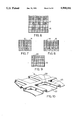
- FIG. 1 is a sectional view of one embodiment of the bipolar cell unit of the invention
- FIG. 2 is a further sectional view of the unit of FIG. 1;
- FIG. 3 is a sectional view of a further embodiment of a cell unit of the invention.
- FIG. 4 is a sectional view of the unit of FIG. 3;
- FIG. 5 is a sectional view along line V--V of FIG. 4;
- FIG. 6 is a sectional view of a non-conducting foam insert
- FIG. 7 is a sectional view of a foam portion with air vents
- FIG. 8 is a sectional view of a foam with a winding air path
- FIG. 9 is a sectional view of a foam member with a single air inlet
- FIG. 10 is a perspective view of a formed anode sheet
- FIG. 11 shows a sectional view of a formed anode sheet with a cathode in position to be attached thereto;
- FIG. 12 is a plan view of the anode sheet of FIG. 11;
- FIG. 13 is a sectional view of a further anode/cathode assembly of the invention.
- FIG. 14 is a detailed fragmentary sectional view of a portion of an anode
- FIG. 15 is a sectional view of a special form of anode
- FIG. 16 is a fragmentary perspective view of battery ends
- FIG. 17 is a sectional view of mounting brackets and an anode
- FIG. 18 is a fragmentary perspective view of a battery case
- FIG. 19 is a further fragmentary perspective view of a battery case.
- FIG. 20 is a fragmentary top plan view of a battery case holding cell units of the invention.
- the metal anode used in the cell unit of the invention can be any aluminum alloy typically used in an aluminum air battery system, with either a saline or alkaline electrolyte.
- the key feature of this invention is that the anode is the major structural member of the bipolar unit.
- the rigid anode causes both the foam/mesh layer or spacer and the anode surface to be both planar and stiff.
- An adhesive or coating may be applied to the cathode side of the anode to protect the anode from attack on that side in the event of leakage and to make electrical connections to the cathode if an electrically conductive adhesive is used.
- a similar adhesive or coating may be applied around the perimeter of the unit to seal the air pocket, protect the anode and/or provide electrical connection depending on the type of unit as described above.
- a typical adhesive for this purpose may be, for example, "Emerson and Cumings Eccobond 64C", an electrically conductive adhesive designed for use where corrosion and salt water is a problem.
- the cathode surface incorporates many of the features of existing air cathodes, e.g. the outer layer may be hydrophilic active carbon containing an appropriate oxygen reducing catalyst.
- the active layer may be applied directly to the outer surface of the foam, e.g. by applying a mixture of binder, active carbon and catalyst.
- An intermediate layer such as carbon fiber paper or metal grid may be added to support the active carbon cathode surface.
- any method of attachment of the active cathode surface to the foam layer may be used which does not block the flow of oxygen to the active layer.
- the foam or mesh layer must be sufficiently rigid to prevent collapse of the air pocket due to the pressure head caused by emersion of the cell unit in electrolyte.
- the foam or mesh layer can be any structure through which oxygen from the air can pass quickly enough to sustain the air cathode reaction at the desired current density.
- Open or closed cell foam, three dimensional grid, or a sponge material may be used.
- Even relatively dense material such as hydrophobic material used in air cathodes may be used for narrow units which operate at low current densities, since for this configuration the distance from the edge of the unit to the electrochemically active surface is short.
- Air channels may be drilled or otherwise machined to improve air flow in order to give the battery improved electrical current. Air may be forced into the channels using an air pump. If the air cathode is sufficiently stiff, then a non-foam material may be used as spacer to support the cathode at three edges or possibly with additional spacers toward the middle of the unit or with a corrugated spacer.
- FIGS. 1 and 2 show one of the simplest unit designs in which an aluminum alloy anode 10 is adhesively attached to a hydrophobic, conducting foam material 12 and an air cathode layer 11 is fixed to the opposite face of the foam by means of an adhesive which does not prevent passage of air from the foam into the cathode.
- FIGS. 3, 4 and 5 shows a design which can be used when a non-conducting foam material 13 is used between the anode 10 and the air cathode 11. Because the foam is non-conducting, an electrical connection must be made between the anode and cathode. If the foam is also non-hydrophobic, then it is necessary to seal the edges of the unit and this can be done by means of edge seals 14 and 15.
- the edge seal 15 is preferably a conductive material such that it provides both a liquid seal and an electrical connection.
- the electrical connection between the anode and cathode may be made by way of connectors 17 extending through the foam 16 as shown in FIG. 6.
- FIGS. 7, 8 and 9 Three forms of holes or channels are shown in FIGS. 7, 8 and 9, with FIG. 7 showing a series of parallel spaced holes 18, FIG. 8 showing an undulating channel 19 and FIG. 9 showing a single inlet hole 20.
- FIGS. 10-12 it will be seen that the anode sheet 22 is pressed into a grid of raised rib portions 23. Between the ribs are shallow three-sided pan-like areas having a pair of side edges 50 and a bottom edge 51, the top end remaining open. A conventional air cathode 21 is then connected to the anode 22 on the ribs 23 by means of ultrasonic welding 52. This can be created in a continuous large sheet and individual smaller units may be formed by cutting along lines 24. Each of these smaller cell units then comprises three sealed edges and one open edge with integral electric connection which is then ready for insertion into a battery container.
- the component 21 may be a metallic grid for an air cathode which is placed over the anode sheet on the ribs 23 and ultrasonically welded as described above.
- the air cathode can then be fabricated on the metallic grid in such a way that the unit edges are sealed as part of the cathode manufacture.
- the individual units are then cut from the larger sheet in the manner described above.
- anode material which would be exposed to electrolyte on the cathode side of the unit should also be so coated. Units should fit snuggly into a battery container in order to minimize shunt currents.
- FIG. 13 Yet another technique for supporting an air cathode 21 on an anode is shown in FIG. 13 where the anode 25 has side edges 26 and crimped edge portions 27 adapted to firmly hold a cathode 21.
- the free edge of the anode may be given a further bend as shown in FIG. 14 to provide both a slot 27 to receive the air cathode and a further slot 28 which can be used for retaining the cell unit in position within a battery case.
- the slots 28 slide along ribs 36 inside a battery case 35 as shown in FIG. 16.
- FIG. 15 Another method for achieving the above purpose is shown in FIG. 15 where the anode comprises an extrusion of a thick anode plate 29 with side edges 30 and a flange portion 31 extending out from each edge portion 30.
- Each flange 31 has integrally formed therewith a T-shaped portion 32 which forms an outward slot 33 and an inward slot 34.
- the two inward slots 34 support an air cathode while the outward slots 33 can again slide along the ribs 36 for mounting in a battery.
- FIG. 17 Another way of achieving the objective of FIG. 15 is shown in FIG. 17 where a pair of end flanges 38 are formed with slots 39 for receiving an anode plate 37, slots 42 for receiving an air cathode and slots 41 for mounting on ribs 36 of the battery.
- FIGS. 18-20 A battery case adapted for use with the present invention is shown in FIGS. 18-20.
- the battery case 43 has end walls 44 and side walls 45.
- the side walls 45 include inwardly projecting portions 46 and inner edges 47 adapted to receive grooves in the vertical edges of bipolar cell units of the invention.
Landscapes
- Chemical & Material Sciences (AREA)
- Chemical Kinetics & Catalysis (AREA)
- Electrochemistry (AREA)
- General Chemical & Material Sciences (AREA)
- Engineering & Computer Science (AREA)
- Manufacturing & Machinery (AREA)
- Hybrid Cells (AREA)
Abstract
A bipolar cell unit is described for use in a metal/air battery, e.g. an aluminum/air battery. Each bipolar cell unit comprises (a) an air cathode having opposed major surfaces, one of the surfaces being exposed to air and the other of the surfaces being adapted for exposure to electrolyte, (b) a metal anode comprising a metal plate having opposed major surfaces with one plate major surface positioned in spaced juxtaposed relation to the cathode surface exposed to air thereby forming an air gap between the anode and cathode, (c) structural means for connecting the air cathode to the anode plate whereby the air cathode is supported by the anode plate such that air is permitted to move through the air gap while electrolyte is excluded and (d) an electrical connection between the anode and cathode.
Description
This invention relates to a bipolar cell unit for use in a metal/air battery, in particular in an aluminum/air battery.
Metal/air batteries produce electricity by the electrochemical coupling of a reactive metallic anode to an air cathode through a suitable electrolyte in a cell. As is well known in the art, an air cathode is a typically sheet-like member, having opposite surfaces respectively exposed to the atmosphere and to the aqueous electrolyte of the cell, in which during cell operation atmospheric oxygen dissociates while metal of the anode oxidizes, providing a usable electric current flow through external circuitry connected between the anode and cathode. The air cathode must be permeable to air but substantially hydrophobic so that aqueous electrolyte will not seep or leak through it, and must incorporate an electrically conductive element to which the external circuitry can be connected; for instance, in present-day commercial practice, the air cathode is commonly constituted of active carbon (with or without an added dissociation-promoting catalyst) containing a finely divided hydrophobic polymeric material and incorporating a metal screen as the conductive element. A variety of anode metals have been used or proposed; among them, alloys of aluminum and alloys of magnesium are considered especially advantageous.
An example of a typical metal/air cell is shown in Hamlen et al., U.S. Pat. No. 4,626,482 issued Dec. 2, l986. It typically comprises a tank defining a reservoir for liquid electrolyte. An air cathode is provided having opposed vertical surfaces with means for supporting the cathode for simultaneous exposure of one of its surfaces to air and the other of its surfaces to electrolyte in the reservoir. A metal anode is provided in the form of a metal plate having opposed vertical major surfaces, disposed for immersion in the electrolyte in the reservoir with one plate major surface positioned in spaced juxtaposition to the other of the cathode surfaces to define therewith an anode-cathode gap for receiving the electrolyte, and with the other plate major surface exposed to electrolyte and facing a region of the reservoir external to the gap. Circuit means are provided for connecting the anode and cathode to an external load.
The conventional air cathode is in the form of a rectangular sheetlike member having two opposed planar major surfaces, being constituted, for example, of two flat layers of an active carbon-hydrophobic polymer composition with a wire screen conductor pressed between them. In order to provide strength to the cathode, the sheetlike member must be mounted in a plastic frame with the edges securely sealed to the frame in the form of a continuous liquid-tight joint. This cathode assembly is then mounted in a framework which holds it in spaced relationship with an anode.
Such a structure is expensive and time-consuming to manufacture and is not amenable to mass production. It is the object of the present invention to provide a greatly simplified form of metal/air bipolar cell unit which will be both much less expensive and simpler to manufacture than any of the prior systems.
The present invention broadly contemplates a bipolar cell unit for a metal/air battery comprising (a) an air cathode having opposed major surfaces, one of the surfaces being exposed to air and the other of the surfaces being adapted for exposure to electrolyte, (b) a metal anode comprising a metal plate having opposed major surfaces with one plate major surface positioned in spaced juxtaposed relation to the cathode surface exposed to air thereby forming an air gap between the anode and cathode, (c) structural means for connecting the air cathode to the anode plate whereby the air cathode is supported by the anode plate such that air is permitted to move through the air gap while electrolyte is excluded and (d) an electrical connection between the anode and cathode.
Preferably, the electrical connection between the anode and cathode is an integral part of the manufacture of the unit such that no electrical connections with wires are necessary to connect the anode and cathode in a complete unit.
The air gap of the invention may be a simple empty air space or it may be a type of foam material with sufficient porosity to allow passage of enough oxygen to sustain the cathode reaction. Typically, each air gap is open at the top to allow passage of air/oxygen.
The object of providing an air gap between the anode and cathode while supporting the cathode primarily by the anode can be achieved in a number of ways as follows:
One way of mounting a cathode to an anode according to the invention is to provide a hydrophobic, electrically conductive foam material as the air gap. The foam may be fixed to the anode by a conductive adhesive and the cathode may be formed directly on the opposite face of the foam or fastened to the foam such that oxygen flow may continue from the foam to the cathode. Such a system is clearly amenable to large scale manufacture where it can be produced in large sheets and simply cut to size for a given battery.
(a) In place of the conductive, hydrophobic foam of Type I, a foam may be used which is hydrophobic but non-conducting. Such a system requires a current collector between the active carbon and the foam, e.g. metal mesh, metal screen, metal coated carbon paper, metal strips, etc. In addition, some form of connection between the current collector and the anode is necessary after the anode/unit has been cut to its final shape. The necessary electrical connections may be made by conductive edges applied to each unit after it is cut to shape or connections may be made through the foam during manufacture e.g. by a polka dot pattern.
(b) It is also possible to use a non-hydrophobic, but electrically conductive foam as the air pocket. In that case the edges of each individual unit must be sealed after they have been cut.
Non-metallic spacers, e.g. corrugated plastic, corrugated cardboard, non-porous spacers at the perimeter of the unit, may be used to maintain the required air pocket. Such a system still uses the anode as the main structural member and there is no need for a rigid cathode frame.
Support of the anode on the cathode by direct means while still creating an air pocket may be achieved by either deforming the anode material such that an air pocket will result or bending the air cathode in a suitable manner. The anode may be formed by conventional metal forming techniques such as extrusion or stretch forming of sheet material. Direct electrical connection of the air cathode to the anode material will occur by crimping or by ultrasonic welding.
Typically, a series of bipolar cell units according to the invention are arranged in spaced, juxtaposed relationship in a tank for holding a body of liquid electrolyte. When liquid electrolyte is added to the tank, the top ends of the cell units remain above the level of the electrolyte such that the open ends of the air gaps are in contact with air/oxygen. Circuit means are provided for connecting the bipolar cell units to an external load.
According to an alternative embodiment, the spaces between the bipolar cell units of this invention may, if desired, be interspersed with open celled, absorbent sponge material which will retain electrolyte, e.g. salt water, upon squeezing, partial emersion and releasing. With a given side of this stack appropriately coated, the stack may be squeezed and dipped into electrolyte such that the air gaps stay electrolyte free, while the active anode/cathode gaps absorb electrolyte. In this way no separate electrolyte container is necessary and shunt currents in a multicell unit would be reduced. Compact multicell batteries can be made in this manner.
Further features and advantages of the invention will be apparent from the detailed description hereinbelow set forth, together with the accompanying drawings.
FIG. 1 is a sectional view of one embodiment of the bipolar cell unit of the invention;
FIG. 2 is a further sectional view of the unit of FIG. 1;
FIG. 3 is a sectional view of a further embodiment of a cell unit of the invention;
FIG. 4 is a sectional view of the unit of FIG. 3;
FIG. 5 is a sectional view along line V--V of FIG. 4;
FIG. 6 is a sectional view of a non-conducting foam insert;
FIG. 7 is a sectional view of a foam portion with air vents;
FIG. 8 is a sectional view of a foam with a winding air path;
FIG. 9 is a sectional view of a foam member with a single air inlet;
FIG. 10 is a perspective view of a formed anode sheet;
FIG. 11 shows a sectional view of a formed anode sheet with a cathode in position to be attached thereto;
FIG. 12 is a plan view of the anode sheet of FIG. 11;
FIG. 13 is a sectional view of a further anode/cathode assembly of the invention;
FIG. 14 is a detailed fragmentary sectional view of a portion of an anode;
FIG. 15 is a sectional view of a special form of anode;
FIG. 16 is a fragmentary perspective view of battery ends;
FIG. 17 is a sectional view of mounting brackets and an anode;
FIG. 18 is a fragmentary perspective view of a battery case;
FIG. 19 is a further fragmentary perspective view of a battery case; and
FIG. 20 is a fragmentary top plan view of a battery case holding cell units of the invention.
The metal anode used in the cell unit of the invention can be any aluminum alloy typically used in an aluminum air battery system, with either a saline or alkaline electrolyte. The key feature of this invention is that the anode is the major structural member of the bipolar unit. The rigid anode causes both the foam/mesh layer or spacer and the anode surface to be both planar and stiff. An adhesive or coating may be applied to the cathode side of the anode to protect the anode from attack on that side in the event of leakage and to make electrical connections to the cathode if an electrically conductive adhesive is used. A similar adhesive or coating may be applied around the perimeter of the unit to seal the air pocket, protect the anode and/or provide electrical connection depending on the type of unit as described above. A typical adhesive for this purpose may be, for example, "Emerson and Cumings Eccobond 64C", an electrically conductive adhesive designed for use where corrosion and salt water is a problem.
The cathode surface incorporates many of the features of existing air cathodes, e.g. the outer layer may be hydrophilic active carbon containing an appropriate oxygen reducing catalyst. The active layer may be applied directly to the outer surface of the foam, e.g. by applying a mixture of binder, active carbon and catalyst. An intermediate layer such as carbon fiber paper or metal grid may be added to support the active carbon cathode surface.
According to another embodiment, it is possible to attach a complete commercially available air cathode to the outer surface of the foam. Any method of attachment of the active cathode surface to the foam layer may be used which does not block the flow of oxygen to the active layer. The foam or mesh layer must be sufficiently rigid to prevent collapse of the air pocket due to the pressure head caused by emersion of the cell unit in electrolyte.
The foam or mesh layer can be any structure through which oxygen from the air can pass quickly enough to sustain the air cathode reaction at the desired current density. Open or closed cell foam, three dimensional grid, or a sponge material may be used. Even relatively dense material such as hydrophobic material used in air cathodes may be used for narrow units which operate at low current densities, since for this configuration the distance from the edge of the unit to the electrochemically active surface is short. Air channels may be drilled or otherwise machined to improve air flow in order to give the battery improved electrical current. Air may be forced into the channels using an air pump. If the air cathode is sufficiently stiff, then a non-foam material may be used as spacer to support the cathode at three edges or possibly with additional spacers toward the middle of the unit or with a corrugated spacer.
The drawings illustrate several preferred embodiments of the present invention and FIGS. 1 and 2 show one of the simplest unit designs in which an aluminum alloy anode 10 is adhesively attached to a hydrophobic, conducting foam material 12 and an air cathode layer 11 is fixed to the opposite face of the foam by means of an adhesive which does not prevent passage of air from the foam into the cathode.
FIGS. 3, 4 and 5 shows a design which can be used when a non-conducting foam material 13 is used between the anode 10 and the air cathode 11. Because the foam is non-conducting, an electrical connection must be made between the anode and cathode. If the foam is also non-hydrophobic, then it is necessary to seal the edges of the unit and this can be done by means of edge seals 14 and 15. The edge seal 15 is preferably a conductive material such that it provides both a liquid seal and an electrical connection. Alternatively, the electrical connection between the anode and cathode may be made by way of connectors 17 extending through the foam 16 as shown in FIG. 6.
It may be desirable to provide holes or channels in the foam to aid the movement of air. Three forms of holes or channels are shown in FIGS. 7, 8 and 9, with FIG. 7 showing a series of parallel spaced holes 18, FIG. 8 showing an undulating channel 19 and FIG. 9 showing a single inlet hole 20.
By altering the shape of the anode portion, it is possible to support the cathode on the anode by direct means. Looking at FIGS. 10-12, it will be seen that the anode sheet 22 is pressed into a grid of raised rib portions 23. Between the ribs are shallow three-sided pan-like areas having a pair of side edges 50 and a bottom edge 51, the top end remaining open. A conventional air cathode 21 is then connected to the anode 22 on the ribs 23 by means of ultrasonic welding 52. This can be created in a continuous large sheet and individual smaller units may be formed by cutting along lines 24. Each of these smaller cell units then comprises three sealed edges and one open edge with integral electric connection which is then ready for insertion into a battery container.
Alternatively, the component 21 may be a metallic grid for an air cathode which is placed over the anode sheet on the ribs 23 and ultrasonically welded as described above. The air cathode can then be fabricated on the metallic grid in such a way that the unit edges are sealed as part of the cathode manufacture. The individual units are then cut from the larger sheet in the manner described above.
To obtain maximum possible use of the above units, it is useful to coat the inside surface of the anode material with a coating to prevent leakage and flooding of the units when they are dissolved electrochemically. Anode material which would be exposed to electrolyte on the cathode side of the unit should also be so coated. Units should fit snuggly into a battery container in order to minimize shunt currents.
Yet another technique for supporting an air cathode 21 on an anode is shown in FIG. 13 where the anode 25 has side edges 26 and crimped edge portions 27 adapted to firmly hold a cathode 21. The free edge of the anode may be given a further bend as shown in FIG. 14 to provide both a slot 27 to receive the air cathode and a further slot 28 which can be used for retaining the cell unit in position within a battery case. Thus, the slots 28 slide along ribs 36 inside a battery case 35 as shown in FIG. 16.
Another method for achieving the above purpose is shown in FIG. 15 where the anode comprises an extrusion of a thick anode plate 29 with side edges 30 and a flange portion 31 extending out from each edge portion 30. Each flange 31 has integrally formed therewith a T-shaped portion 32 which forms an outward slot 33 and an inward slot 34. The two inward slots 34 support an air cathode while the outward slots 33 can again slide along the ribs 36 for mounting in a battery.
Another way of achieving the objective of FIG. 15 is shown in FIG. 17 where a pair of end flanges 38 are formed with slots 39 for receiving an anode plate 37, slots 42 for receiving an air cathode and slots 41 for mounting on ribs 36 of the battery.
A battery case adapted for use with the present invention is shown in FIGS. 18-20. Thus, the battery case 43 has end walls 44 and side walls 45. The side walls 45 include inwardly projecting portions 46 and inner edges 47 adapted to receive grooves in the vertical edges of bipolar cell units of the invention.
It is to be understood that the invention is not limited to the features and embodiments hereinabove specifically set forth but may be carried out in other ways without departure from its spirit.
Claims (8)
1. A bipolar cell unit for a metal/air battery comprising an (a) air cathode having opposed major surfaces, one of said surfaces being exposed to air and the other of said surfaces being adapted for exposure to electrolyte, (b) a metal anode comprising a metal plate having opposed major surfaces with one plate major surface positioned in spaced juxtaposed relation to said cathode surface exposed to air thereby forming an air gap between the anode and cathode, (c) an air permeable, hydrophobic, nonconducting foam material connecting said air cathode to said anode plate whereby the air cathode is supported by the anode plate such that air is permitted to move through said air gap while electrolyte is excluded and (d) an electrical connection between the anode and cathode.
2. A bipolar cell unit according to claim 1 wherein the structural means connecting the cathode to the anode comprises an air permeable hydrophobic, electrically conductive foam material.
3. A bipolar cell unit according to claim 1 wherein the electrical connection comprises electrically conductive edge seals which seal at least one edge of the cell unit.
4. A bipolar cell unit according to claim 1 wherein the electrical connection comprises connector pieces extending through the foam between the cathode and anode.
5. A bipolar cell unit according to claim 1 wherein the structural means connecting the cathode to the anode comprises an air permeable, non-hydrophobic, electrically conductive foam material, the edges of the foam adapted for immersion in electrolyte being sealed against fluid penetration.
6. A bipolar cell unit according to claim 1, wherein the structural means connecting the cathode to the anode comprises projecting portions of an anode plate, said projecting portions holding the air cathode.
7. A bipolar cell unit according to claim 1, wherein the structural means connecting the cathode to the anode comprises edge flanges with inwardly directed slots for holding both the anode and cathode.
8. A bipolar cell unit according to claim 7 wherein the edge flanges also have outwardly directed slots for engaging vertical ribs on inner battery walls.
Priority Applications (1)
| Application Number | Priority Date | Filing Date | Title |
|---|---|---|---|
| US07/382,533 US4988581A (en) | 1989-07-19 | 1989-07-19 | Metal-air bipolar cell unit |
Applications Claiming Priority (1)
| Application Number | Priority Date | Filing Date | Title |
|---|---|---|---|
| US07/382,533 US4988581A (en) | 1989-07-19 | 1989-07-19 | Metal-air bipolar cell unit |
Publications (1)
| Publication Number | Publication Date |
|---|---|
| US4988581A true US4988581A (en) | 1991-01-29 |
Family
ID=23509379
Family Applications (1)
| Application Number | Title | Priority Date | Filing Date |
|---|---|---|---|
| US07/382,533 Expired - Fee Related US4988581A (en) | 1989-07-19 | 1989-07-19 | Metal-air bipolar cell unit |
Country Status (1)
| Country | Link |
|---|---|
| US (1) | US4988581A (en) |
Cited By (23)
| Publication number | Priority date | Publication date | Assignee | Title |
|---|---|---|---|---|
| US5240785A (en) * | 1989-04-04 | 1993-08-31 | Koa Oil Company, Limited | Air cell |
| US5328778A (en) * | 1991-12-16 | 1994-07-12 | Matsi, Inc. | Metal-air cells comprising collapsible foam members and means for minimizing internal pressure buildup |
| US5441824A (en) * | 1994-12-23 | 1995-08-15 | Aerovironment, Inc. | Quasi-bipolar battery requiring no casing |
| US5458988A (en) * | 1993-08-10 | 1995-10-17 | Matsi, Inc. | Metal-air-cells having improved anode assemblies |
| WO2001028011A1 (en) * | 1999-10-08 | 2001-04-19 | Reveo, Inc. | Electrochemical electrode for fuel cell |
| EP1396899A2 (en) * | 2002-09-07 | 2004-03-10 | GCT Gas-Cell-Tec AG | Gas generating cell or battery and method for manufacturing the same |
| US20050026351A1 (en) * | 1999-08-25 | 2005-02-03 | Micron Technology, Inc. | Packaging of electronic chips with air-bridge structures |
| US20050029663A1 (en) * | 2000-02-22 | 2005-02-10 | Micron Technology, Inc. | Polynorbornene foam insulation for integrated circuits |
| EP1843418A1 (en) * | 2006-03-31 | 2007-10-10 | Neos International GmbH | Safety switching for battery cells of a battery |
| WO2007112912A1 (en) * | 2006-03-31 | 2007-10-11 | Neos International Gmbh | Safety circuit for battery cells of a battery |
| US20130115531A1 (en) * | 2010-07-21 | 2013-05-09 | Eos Energy Storage, Llc | Electrically rechargeable, metal-air battery systems and methods |
| US20140120429A1 (en) * | 2011-06-24 | 2014-05-01 | Commissariat A L'energie Atomique Et Aux Energies Alternatives | High capacity gaseous diffusion electrode |
| CN104067441A (en) * | 2012-01-25 | 2014-09-24 | 日产自动车株式会社 | Air battery and battery pack using same |
| US9680193B2 (en) | 2011-12-14 | 2017-06-13 | Eos Energy Storage, Llc | Electrically rechargeable, metal anode cell and battery systems and methods |
| US9879760B2 (en) | 2002-11-25 | 2018-01-30 | Delbert Tesar | Rotary actuator with shortest force path configuration |
| US9915319B2 (en) | 2014-09-29 | 2018-03-13 | Delbert Tesar | Compact parallel eccentric rotary actuator |
| US10414271B2 (en) | 2013-03-01 | 2019-09-17 | Delbert Tesar | Multi-speed hub drive wheels |
| US10422387B2 (en) | 2014-05-16 | 2019-09-24 | Delbert Tesar | Quick change interface for low complexity rotary actuator |
| US10464413B2 (en) | 2016-06-24 | 2019-11-05 | Delbert Tesar | Electric multi-speed hub drive wheels |
| US10964982B2 (en) | 2016-09-16 | 2021-03-30 | Agency For Science, Technology And Research | Rechargeable metal-air battery cell, a battery stack and method of manufacturing the same |
| US11014658B1 (en) | 2015-01-02 | 2021-05-25 | Delbert Tesar | Driveline architecture for rotorcraft featuring active response actuators |
| US11390956B1 (en) | 2021-06-01 | 2022-07-19 | Verdagy, Inc. | Anode and/or cathode pan assemblies in an electrochemical cell, and methods to use and manufacture thereof |
| FR3131095A1 (en) * | 2021-12-21 | 2023-06-23 | Centre National De La Recherche Scientifique | Air electrode and its method of manufacture |
Citations (9)
| Publication number | Priority date | Publication date | Assignee | Title |
|---|---|---|---|---|
| US3043898A (en) * | 1956-04-24 | 1962-07-10 | Aerojet General Co | Gas depolarized battery |
| US3316167A (en) * | 1961-09-01 | 1967-04-25 | Exxon Research Engineering Co | Multi-cell reactor in series |
| US3598655A (en) * | 1968-04-01 | 1971-08-10 | Gen Electric | Metal-air cell |
| US3682706A (en) * | 1970-06-18 | 1972-08-08 | Michel N Yardney | Gas depolarized cell |
| US4184008A (en) * | 1977-04-04 | 1980-01-15 | Yuichi Watakabe | Float type metal-air battery |
| US4463064A (en) * | 1982-05-15 | 1984-07-31 | Accumulatorenwerke Hoppecke Carl Zoellner & Sohn Gmbh & Co. Kg | Galvanic element, especially metal-air-cell |
| US4507367A (en) * | 1981-07-24 | 1985-03-26 | Accumulatorenwerke Hoppecke Carl Zoellner & Sohn Gmbh & Co. Kg | Galvanic element, particularly a metal-air cell |
| US4626482A (en) * | 1985-11-18 | 1986-12-02 | Alupower, Inc. | Metal/air batteries |
| US4693946A (en) * | 1986-03-11 | 1987-09-15 | Eltech Systems Corporation | Battery with modular air cathode and anode cage |
-
1989
- 1989-07-19 US US07/382,533 patent/US4988581A/en not_active Expired - Fee Related
Patent Citations (9)
| Publication number | Priority date | Publication date | Assignee | Title |
|---|---|---|---|---|
| US3043898A (en) * | 1956-04-24 | 1962-07-10 | Aerojet General Co | Gas depolarized battery |
| US3316167A (en) * | 1961-09-01 | 1967-04-25 | Exxon Research Engineering Co | Multi-cell reactor in series |
| US3598655A (en) * | 1968-04-01 | 1971-08-10 | Gen Electric | Metal-air cell |
| US3682706A (en) * | 1970-06-18 | 1972-08-08 | Michel N Yardney | Gas depolarized cell |
| US4184008A (en) * | 1977-04-04 | 1980-01-15 | Yuichi Watakabe | Float type metal-air battery |
| US4507367A (en) * | 1981-07-24 | 1985-03-26 | Accumulatorenwerke Hoppecke Carl Zoellner & Sohn Gmbh & Co. Kg | Galvanic element, particularly a metal-air cell |
| US4463064A (en) * | 1982-05-15 | 1984-07-31 | Accumulatorenwerke Hoppecke Carl Zoellner & Sohn Gmbh & Co. Kg | Galvanic element, especially metal-air-cell |
| US4626482A (en) * | 1985-11-18 | 1986-12-02 | Alupower, Inc. | Metal/air batteries |
| US4693946A (en) * | 1986-03-11 | 1987-09-15 | Eltech Systems Corporation | Battery with modular air cathode and anode cage |
Cited By (38)
| Publication number | Priority date | Publication date | Assignee | Title |
|---|---|---|---|---|
| US5240785A (en) * | 1989-04-04 | 1993-08-31 | Koa Oil Company, Limited | Air cell |
| US5328778A (en) * | 1991-12-16 | 1994-07-12 | Matsi, Inc. | Metal-air cells comprising collapsible foam members and means for minimizing internal pressure buildup |
| US5458988A (en) * | 1993-08-10 | 1995-10-17 | Matsi, Inc. | Metal-air-cells having improved anode assemblies |
| US5441824A (en) * | 1994-12-23 | 1995-08-15 | Aerovironment, Inc. | Quasi-bipolar battery requiring no casing |
| US20060244112A1 (en) * | 1999-08-25 | 2006-11-02 | Micron Technology, Inc. | Packaging of electronic chips with air-bridge structures |
| US7387912B2 (en) | 1999-08-25 | 2008-06-17 | Micron Technology, Inc. | Packaging of electronic chips with air-bridge structures |
| US7335965B2 (en) | 1999-08-25 | 2008-02-26 | Micron Technology, Inc. | Packaging of electronic chips with air-bridge structures |
| US20050026351A1 (en) * | 1999-08-25 | 2005-02-03 | Micron Technology, Inc. | Packaging of electronic chips with air-bridge structures |
| US20070042595A1 (en) * | 1999-08-25 | 2007-02-22 | Micron Technology, Inc. | Packaging of electronic chips with air-bridge structures |
| US20050285220A1 (en) * | 1999-08-25 | 2005-12-29 | Micron Technology, Inc. | Packaging of electronic chips with air-bridge structures |
| WO2001028011A1 (en) * | 1999-10-08 | 2001-04-19 | Reveo, Inc. | Electrochemical electrode for fuel cell |
| US6368751B1 (en) * | 1999-10-08 | 2002-04-09 | Reves, Inc. | Electrochemical electrode for fuel cell |
| US20050029663A1 (en) * | 2000-02-22 | 2005-02-10 | Micron Technology, Inc. | Polynorbornene foam insulation for integrated circuits |
| EP1396899A3 (en) * | 2002-09-07 | 2006-11-22 | GCT Gas-Cell-Tec AG | Gas generating cell or battery and method for manufacturing the same |
| EP1396899A2 (en) * | 2002-09-07 | 2004-03-10 | GCT Gas-Cell-Tec AG | Gas generating cell or battery and method for manufacturing the same |
| US9879760B2 (en) | 2002-11-25 | 2018-01-30 | Delbert Tesar | Rotary actuator with shortest force path configuration |
| EP1843418A1 (en) * | 2006-03-31 | 2007-10-10 | Neos International GmbH | Safety switching for battery cells of a battery |
| WO2007112912A1 (en) * | 2006-03-31 | 2007-10-11 | Neos International Gmbh | Safety circuit for battery cells of a battery |
| US20180366799A1 (en) * | 2010-07-21 | 2018-12-20 | Eos Energy Storage, Llc | Electrically rechargeable, metal-air battery systems and methods |
| US20130115531A1 (en) * | 2010-07-21 | 2013-05-09 | Eos Energy Storage, Llc | Electrically rechargeable, metal-air battery systems and methods |
| US9368802B2 (en) * | 2011-06-24 | 2016-06-14 | Commissariat à l'Energie Atomique et aux Energies Alternatives | High capacity gaseous diffusion electrode |
| US20140120429A1 (en) * | 2011-06-24 | 2014-05-01 | Commissariat A L'energie Atomique Et Aux Energies Alternatives | High capacity gaseous diffusion electrode |
| US9680193B2 (en) | 2011-12-14 | 2017-06-13 | Eos Energy Storage, Llc | Electrically rechargeable, metal anode cell and battery systems and methods |
| CN104067441B (en) * | 2012-01-25 | 2017-03-08 | 日产自动车株式会社 | Air cell and the battery pack using the air cell |
| US9502741B2 (en) | 2012-01-25 | 2016-11-22 | Nissan Motor Co., Ltd. | Air battery and battery pack using same |
| EP2808937A4 (en) * | 2012-01-25 | 2015-08-05 | Nissan Motor | AIR BATTERY AND BATTERY PACK USING THE LATTER |
| CN104067441A (en) * | 2012-01-25 | 2014-09-24 | 日产自动车株式会社 | Air battery and battery pack using same |
| US10414271B2 (en) | 2013-03-01 | 2019-09-17 | Delbert Tesar | Multi-speed hub drive wheels |
| US10422387B2 (en) | 2014-05-16 | 2019-09-24 | Delbert Tesar | Quick change interface for low complexity rotary actuator |
| US9915319B2 (en) | 2014-09-29 | 2018-03-13 | Delbert Tesar | Compact parallel eccentric rotary actuator |
| US11014658B1 (en) | 2015-01-02 | 2021-05-25 | Delbert Tesar | Driveline architecture for rotorcraft featuring active response actuators |
| US10464413B2 (en) | 2016-06-24 | 2019-11-05 | Delbert Tesar | Electric multi-speed hub drive wheels |
| US10964982B2 (en) | 2016-09-16 | 2021-03-30 | Agency For Science, Technology And Research | Rechargeable metal-air battery cell, a battery stack and method of manufacturing the same |
| US11390956B1 (en) | 2021-06-01 | 2022-07-19 | Verdagy, Inc. | Anode and/or cathode pan assemblies in an electrochemical cell, and methods to use and manufacture thereof |
| WO2022256043A1 (en) * | 2021-06-01 | 2022-12-08 | Verdagy, Inc. | Anode and/or cathode pan assemblies in an electrochemical cell, and methods to use and manufacture thereof |
| US12209319B2 (en) | 2021-06-01 | 2025-01-28 | Verdagy, Inc. | Anode and/or cathode pan assemblies in an electrochemical cell, and methods to use and manufacture thereof |
| FR3131095A1 (en) * | 2021-12-21 | 2023-06-23 | Centre National De La Recherche Scientifique | Air electrode and its method of manufacture |
| WO2023118155A1 (en) * | 2021-12-21 | 2023-06-29 | Centre National De La Recherche Scientifique | Air electrode and method for manufacturing same |
Similar Documents
| Publication | Publication Date | Title |
|---|---|---|
| US4988581A (en) | Metal-air bipolar cell unit | |
| US4246324A (en) | Consumable replaceable anodes for batteries | |
| US5458988A (en) | Metal-air-cells having improved anode assemblies | |
| US5190833A (en) | Electrodes for metal/air batteries and fuel cells and bipolar metal/air batteries incorporating the same | |
| US4693946A (en) | Battery with modular air cathode and anode cage | |
| US4927717A (en) | Bipolar metal/air battery | |
| US4828939A (en) | Bipolar metal/air battery | |
| US5328778A (en) | Metal-air cells comprising collapsible foam members and means for minimizing internal pressure buildup | |
| EP0188873B1 (en) | Lightweight bipolar metal-gas battery | |
| US5145752A (en) | Electrodes for metal/air batteries and bipolar metal/air batteries incorporating the same | |
| US4950561A (en) | Metal-air battery with easily removable anodes | |
| US5185218A (en) | Electrodes for metal/air batteries and fuel cells and metal/air batteries incorporating the same | |
| GB1176486A (en) | Improvements in or relating to Electrochemical Cells | |
| JPH0696786A (en) | Electrolytic tank and cellular structure for fuel cell | |
| WO2019203130A1 (en) | Air electrode, metal-air battery, and method for manufacturing metal-air battery | |
| US4296184A (en) | Electrochemical cell | |
| US4514474A (en) | Air cathode structure manufacture | |
| EP0417324B1 (en) | Air cell | |
| US4756980A (en) | Battery with modular air cathode and anode cage | |
| US4271003A (en) | Chemoelectric cell | |
| US5225292A (en) | Internally folded expanded metal electrode for battery construction | |
| EP0047792B1 (en) | Battery, gas depolarized electrochemical cell and bipolar element for the battery | |
| US4503132A (en) | Fuel cell electrode | |
| US3592695A (en) | Metal-air cell including a composite laminar gas diffusion cathode | |
| US4181776A (en) | Chemoelectric cell |
Legal Events
| Date | Code | Title | Description |
|---|---|---|---|
| AS | Assignment |
Owner name: ALCAN INTERNATIONAL LIMITED, CANADA Free format text: ASSIGNMENT OF ASSIGNORS INTEREST.;ASSIGNOR:WYCLIFFE, PAUL A.;REEL/FRAME:005116/0609 Effective date: 19890714 |
|
| REMI | Maintenance fee reminder mailed | ||
| LAPS | Lapse for failure to pay maintenance fees | ||
| FP | Lapsed due to failure to pay maintenance fee |
Effective date: 19950202 |
|
| STCH | Information on status: patent discontinuation |
Free format text: PATENT EXPIRED DUE TO NONPAYMENT OF MAINTENANCE FEES UNDER 37 CFR 1.362 |