US4902629A - Apparatus and processes for facilitating reaction between analyte and test reagent system - Google Patents
Apparatus and processes for facilitating reaction between analyte and test reagent system Download PDFInfo
- Publication number
- US4902629A US4902629A US07/106,573 US10657387A US4902629A US 4902629 A US4902629 A US 4902629A US 10657387 A US10657387 A US 10657387A US 4902629 A US4902629 A US 4902629A
- Authority
- US
- United States
- Prior art keywords
- capillary
- test reagent
- reagent system
- sample
- liquid
- Prior art date
- Legal status (The legal status is an assumption and is not a legal conclusion. Google has not performed a legal analysis and makes no representation as to the accuracy of the status listed.)
- Expired - Fee Related
Links
Images


Classifications
-
- B—PERFORMING OPERATIONS; TRANSPORTING
- B01—PHYSICAL OR CHEMICAL PROCESSES OR APPARATUS IN GENERAL
- B01L—CHEMICAL OR PHYSICAL LABORATORY APPARATUS FOR GENERAL USE
- B01L3/00—Containers or dishes for laboratory use, e.g. laboratory glassware; Droppers
- B01L3/50—Containers for the purpose of retaining a material to be analysed, e.g. test tubes
- B01L3/502—Containers for the purpose of retaining a material to be analysed, e.g. test tubes with fluid transport, e.g. in multi-compartment structures
- B01L3/5027—Containers for the purpose of retaining a material to be analysed, e.g. test tubes with fluid transport, e.g. in multi-compartment structures by integrated microfluidic structures, i.e. dimensions of channels and chambers are such that surface tension forces are important, e.g. lab-on-a-chip
- B01L3/502738—Containers for the purpose of retaining a material to be analysed, e.g. test tubes with fluid transport, e.g. in multi-compartment structures by integrated microfluidic structures, i.e. dimensions of channels and chambers are such that surface tension forces are important, e.g. lab-on-a-chip characterised by integrated valves
-
- G—PHYSICS
- G01—MEASURING; TESTING
- G01N—INVESTIGATING OR ANALYSING MATERIALS BY DETERMINING THEIR CHEMICAL OR PHYSICAL PROPERTIES
- G01N33/00—Investigating or analysing materials by specific methods not covered by groups G01N1/00 - G01N31/00
- G01N33/48—Biological material, e.g. blood, urine; Haemocytometers
- G01N33/50—Chemical analysis of biological material, e.g. blood, urine; Testing involving biospecific ligand binding methods; Immunological testing
- G01N33/53—Immunoassay; Biospecific binding assay; Materials therefor
- G01N33/5302—Apparatus specially adapted for immunological test procedures
-
- G—PHYSICS
- G01—MEASURING; TESTING
- G01N—INVESTIGATING OR ANALYSING MATERIALS BY DETERMINING THEIR CHEMICAL OR PHYSICAL PROPERTIES
- G01N33/00—Investigating or analysing materials by specific methods not covered by groups G01N1/00 - G01N31/00
- G01N33/48—Biological material, e.g. blood, urine; Haemocytometers
- G01N33/50—Chemical analysis of biological material, e.g. blood, urine; Testing involving biospecific ligand binding methods; Immunological testing
- G01N33/53—Immunoassay; Biospecific binding assay; Materials therefor
- G01N33/543—Immunoassay; Biospecific binding assay; Materials therefor with an insoluble carrier for immobilising immunochemicals
- G01N33/54366—Apparatus specially adapted for solid-phase testing
-
- B—PERFORMING OPERATIONS; TRANSPORTING
- B01—PHYSICAL OR CHEMICAL PROCESSES OR APPARATUS IN GENERAL
- B01L—CHEMICAL OR PHYSICAL LABORATORY APPARATUS FOR GENERAL USE
- B01L2300/00—Additional constructional details
- B01L2300/08—Geometry, shape and general structure
- B01L2300/0832—Geometry, shape and general structure cylindrical, tube shaped
- B01L2300/0838—Capillaries
-
- B—PERFORMING OPERATIONS; TRANSPORTING
- B01—PHYSICAL OR CHEMICAL PROCESSES OR APPARATUS IN GENERAL
- B01L—CHEMICAL OR PHYSICAL LABORATORY APPARATUS FOR GENERAL USE
- B01L2400/00—Moving or stopping fluids
- B01L2400/04—Moving fluids with specific forces or mechanical means
- B01L2400/0403—Moving fluids with specific forces or mechanical means specific forces
- B01L2400/0406—Moving fluids with specific forces or mechanical means specific forces capillary forces
-
- B—PERFORMING OPERATIONS; TRANSPORTING
- B01—PHYSICAL OR CHEMICAL PROCESSES OR APPARATUS IN GENERAL
- B01L—CHEMICAL OR PHYSICAL LABORATORY APPARATUS FOR GENERAL USE
- B01L2400/00—Moving or stopping fluids
- B01L2400/06—Valves, specific forms thereof
- B01L2400/0633—Valves, specific forms thereof with moving parts
- B01L2400/065—Valves, specific forms thereof with moving parts sliding valves
-
- Y—GENERAL TAGGING OF NEW TECHNOLOGICAL DEVELOPMENTS; GENERAL TAGGING OF CROSS-SECTIONAL TECHNOLOGIES SPANNING OVER SEVERAL SECTIONS OF THE IPC; TECHNICAL SUBJECTS COVERED BY FORMER USPC CROSS-REFERENCE ART COLLECTIONS [XRACs] AND DIGESTS
- Y10—TECHNICAL SUBJECTS COVERED BY FORMER USPC
- Y10S—TECHNICAL SUBJECTS COVERED BY FORMER USPC CROSS-REFERENCE ART COLLECTIONS [XRACs] AND DIGESTS
- Y10S435/00—Chemistry: molecular biology and microbiology
- Y10S435/805—Test papers
Definitions
- This invention relates generally to new and improved apparatus and processes for facilitating reaction between analyte contained in a sample and test reagent system, and more particularly relates to new and improved apparatus and processes for enhancing facilitation of reaction between analyte contained in a sample and test reagent system wherein flow produced by capillary attraction, particularly turbulent flow, is utilized to bring a liquid one of sample and test reagent system into contact, particularly turbulent contact, with the other of the sample and test regent system to enhance facilitation of the reaction.
- test reagent system as used in the specification and appended claims is used to define a system which has been adapted to react with the analyte upon its presence or presence to a significant extent.
- Analyte is typically contained in a sample, usually a liquid sample, for example the sample may be blood and the blood may be analyzed or a determination made with regard thereto as to whether or not antibodies to the human immunodeficiency virus (HIV) are present in the blood such antibodies being the analyte.
- the test reagent system may be latex beads coated with a certain human immunodeficiency virus (HIV) antigen, upon the antibodies being present and brought into contact with the antigen, an agglutination reaction occurs indicating a positive analysis or determination; thus it will be understood further that in the context of the present invention the analyte may be an antibody reagent and the test reagent system may be an antigen reagent, or vice versa.
- HIV human immunodeficiency virus
- the analyte may be glucose contained in blood or blood serum
- the test reagent system may be the Trinder reagent system, a colorimetric test reagent system, and upon the analyte being brought into contact with the Trinder test reagent system, and glucose analyte being present in the blood or blood serum sample, a change in color occurs to indicate, or provide the determination that, glucose is present in the sample.
- Other examples of analyte contained in a sample e.g. liquid sample, are penicillin contained in milk, amylase contained in saliva, sodium chloride contained in sweat, bacteria contained in carrot juice; in each of these instances, a suitable test reagent system, e.g. a liquid test reagent system, would be provided to react with the analyte upon the analyte being present at least to a significant extent.
- Analyte determination or analysis has been advanced by innumerable technological advances, yet many of the analyte determinations performed today require handling of sample containing the analyte and/or test reagent system; the use of ancillary equipment such as timers, test reagent system and/or sample containers or cuvettes; mixing devices (e.g. centrifuges, rotary mixers, mixing coils, pump, etc.) and reading devices (e.g. scanners, photometers, etc.). Additionally, the amounts of sample containing analyte/test reagent system required for testing may be large thereby increasing the cost per test to the point where they are at least undesirably high if not prohibitive for a large group of the present population.
- ancillary equipment such as timers, test reagent system and/or sample containers or cuvettes
- mixing devices e.g. centrifuges, rotary mixers, mixing coils, pump, etc.
- reading devices e.g. scanners, photometer
- Slide tests, and slide test apparatus are well known to those skilled in the analyte determination or analysis art, yet to perform a slide test requires the addition and mixing of the sample containing analyte and test reagent system for a prescribed time period whereafter the reaction, or test result, is then interpreted by direct visual observation or by an automatic optical reader.
- Typical slide test apparatus and processes are disclosed in U.S. Pat. No. 4,022,521 to Hall et al. patented May 10, 1977, U.S. Pat. No. 4,088,448 to Lilja et al. patented May 9, 1978, U.S. Pat. No. 4,171,866 to Tolles patented Oct. 28, 1979, and U.S. Pat. No.
- optical determination means determination of the presence or absence of a reaction between analyte and test reagent system, for example by the human eye, a beam of light such as used in a turbidimeter, and the like.
- apparatus and processes of the present invention utilize “capillary means” and that "capillary means” is used in the specification and the appended claims to include a capillary tube having a small bore, or other structure such as a relatively large body of material having a small bore, into which bore a liquid may be elevated or drawn by capillary attraction.
- liquid as used in the specification and the appended claims means a liquid or other medium capable of being elevated or drawn into capillary means by capillary attraction.
- turbulent flow as used in the specification and the appended claims is used to define fluid, e.g. liquid flow, in which the velocity at a given point changes constantly in magnitude and direction----contrasted with laminar flow; the term “turbulent flow” is further defined hereinbelow in the Description of the Invention and further contrasted with laminar flow.
- the primary object of the present invention is to satisfy the foregoing needs which are satisfied by apparatus and processes of the present invention wherein reaction between analyte contained in a sample and test reagent system, at least one of which is a liquid, is facilitated by placing the liquid one of the sample and test reagent system in a reservoir, placing the other of the sample and test reagent system in capillary means, e.g.
- a capillary tube dimensioned for entry into the reservoir, mounting the reservoir and capillary means for at least relative movement towards each other and entry of the capillary means into the reservoir, and providing relative movement towards each other and entry of the capillary means into the reservoir to draw by capillary attraction the liquid one of the sample and test reagent system from the reservoir into the capillary means and to bring the analyte and test reagent system into contact in the capillary means and facilitate the reaction.
- FIG. 1 is a top or plan view of apparatus embodying the present invention, which apparatus is particularly useful for practicing the process of the present invention
- FIG. 2 is a sectional view taken generally along the line 2--2 in FIG. 1 in the direction of the arrows;
- FIG. 3 is a cross-sectional view, enlarged, and taken generally along the line 3--3 in FIG. 1 in the direction of the arrows;
- FIG. 4 is another plan view of the apparatus of FIG. 1 but showing the capillary means containing one of test reagent system and analyte advanced toward and having entered the reservoir containing the other of the test reagent system and analyte;
- FIGS. 5, 6 and 7 are, respectively, enlarged cross-sectional views illustrating various embodiments of the bore configuration of capillary means embodying the present invention and particularly useful for providing turbulent flow to a liquid by capillary attraction;
- FIG. 8 is a diagrammatical illustration of laminar liquid flow
- FIG. 9 is a diagrammatical illustration of turbulent fluid flow
- FIG. 10 is a diagrammatic illustration of turbulent flow enhanced by particle agglutination formation
- FIG. 11 is a composite diagrammatical illustration of agglutinated particle distribution provided with a gradient produced by laminar capillary flow;
- FIG. 12 is a composite diagrammatical illustration of agglutinated particle distribution provided with a gradient produced by turbulent capillary flow
- FIGS. 13 and 14 are diagrammatical illustrations in connection with a longitudinal-sectional view of a capillary tube illustrating capillary attraction driven turbulence contact gradient;
- FIGS. 15, 16 and 17 are perspective views of apparatus embodying the present invention, particularly useful for practicing the processes of the present invention and illustrating the apparatus in three different stages of operation;
- FIG. 18 is a perspective view, in partial cross-section, illustrating a further embodiment of apparatus embodying the present invention.
- FIG. 19 is a cross-sectional view of a portion of the apparatus of FIG. 18 along the plane 19 in the direction of the arrows;
- FIG. 20 is a perspective view, partially in a cross-section, of a still further embodiment of apparatus embodying the present invention, particularly useful for practicing processes of the present invention.
- FIG. 21 is a perspective view, partially in cross-section, of yet another embodiment of apparatus embodying the present invention and particularly useful for practicing processes of the present invention.
- Apparatus 10 may include a base or mounting member 12, a capillary tube 14 mounted slidably on the mounting member 12, and a reservoir 16 provided stationarily on the mounting member.
- the capillary tube 14 is provided with a bore 18 and the bottom of the capillary tube 14 may be secured, such as by a suitable adhesive, to a slide member 20 received slidably within a groove 22 formed in the mounting member 12, as may be seen best in FIG.
- slide member 20 and groove 22 may be provided with complementary, cross-sectional shapes to assist maintaining the slide member in the groove.
- the reservoir 16 may be embodied as illustrated in FIGS. 1 and 2 as a capillary tube having a bore 24 and the reservoir 16 may be formed integrally with the mounting member 12 or formed separately and secured thereto in the position shown by a suitable adhesive. It will be understood that the capillary tube 14 is dimensioned, i.e. provided with a cross-sectional size and shape, permitting entry of the capillary tube 14 into the bore 24 of the reservoir 16.
- the capillary tube bore 18 has an axis 18A
- the reservoir bore 24 has an axis 24A
- the capillary tube 14 and reservoir 16 are mounted coaxially in opposed, spaced apart, end-to-end relationship
- the capillary tube 14 is mounted slidably on the mounting member 12 through slide member 20, for movement towards and entry of at least the forward end thereof into the bore 24 of the reservoir 16.
- liquid sample 26 (indicated by arrow 26) containing an analyte may be placed in the capillary tube 14 by pipetting
- liquid test reagent system 30 (indicated by arrow 30) may be placed in the reservoir or capillary tube 16 by pipetting; alternatively, the sample 26 and liquid test reagent system 30 may be placed in the capillary tube and reservoir by a dropper, or the like.
- the capillary tube 14 having the liquid sample 26 placed therein may be advanced by the fingers of an operator, in the direction of the arrow 34, towards the reservoir 16 sufficiently far to cause entry of the forward end of the capillary tube 14 into the reservoir 16 sufficiently far to cause the forward end of the capillary tube to engage at least the meniscus of the liquid test reagent system 30 residing in the bore 24 of the reservoir 16.
- the liquid test reagent system 30 is drawn by capillary attraction from the reservoir 16 into the bore 18 of the capillary tube 14 to bring the liquid test reagent system 30 into contact with the analyte contained in the sample 26 in the bore 18 of the capillary tube 14 and facilitate reaction therebetween.
- the capillary tube 14 may be glass and, in accordance with the further teachings of the present invention, may be provided with a non-circular, cross-section, particularly having a flat top portion, as illustrated in FIG. 3 whereby optical determination, especially visualization by the human eye, may be enhanced or facilitated.
- the bore 18 of the capillary tube 14, FIG. 3 may be provided with a non-circular, cross-section having mutually perpendicular major and minor axes 36 and 38 wherein, in the preferred embodiment, the major-to-minor axis ratio is approximately 10:1.
- such bore having a non-circular, cross-section provides turbulent flow by capillary attraction to the liquid test reagent system residing in the bore 24 of the reservoir 16 to draw the liquid test reagent system 30 from the reservoir 16 into the bore 18 of the capillary tube 14 with turbulent flow and to bring the liquid test reagent system 30 into turbulent contact with the analyte contained in the sample 26 residing in the bore 18 and enhance facilitation of reaction therebetween by, for example, increasing the number of reaction sites available between the analyte and test reagent system due to the turbulent contact therebetween.
- the bore 18 may be defined by opposed flat surfaces interconnected by opposed generally circular, outwardly extending surfaces as shown having major and minor axes 36 and 38 of the ratio noted above.
- the capillary tube 14A may be provided with an oval, cross-sectional shape providing a bore 18A of oval, cross-sectional shape having major and minor axes 36A and 38A of the ratio noted above.
- the capillary tube 14B may be provided with a bore 18B having a non-circular, cross-sectional shape which is generally lemniscate (i.e. in the shape of a figure eight ("8") and more particularly an open figure eight (“8")) as shown and also having major and minor axes 36B and 38B of the above-noted major-to-minor axis ratio.
- FIG. 9 there is illustrated a longitudinal section through circular tubing T2 showing a turbulent flow pattern
- A shows flow not always parallel to the tube axis
- ⁇ shows the shedding of an eddy, a type of turbulence, into the flow from behind a rough spot on the wall
- C shows the time-averaged velocity profile, which has been flattened compared to the laminar liquid flow profile shown in FIG. 8.
- Velocity at the wall of the tubing T2 is zero, as in laminar flow, but the parabolic velocity profile is flattened into a logarithmic one.
- Turbulent flow has more friction than laminar flow, and flow becomes turbulent when inertial forces (that perpetuate flow instabilities) dominate viscous forces (that dampen instabilities).
- the Reynolds number is a dimensionless ratio of these forces.
- R e represents the Reynolds number
- V represents average linear velocity in cm sec -1
- D represents diameter in cm
- Turbulence usually starts when the Reynolds number reaches the 2000 to 4000 range. Increasing any of the above three variables in the numerator promotes turbulence.
- this type of turbulent flow may be used to enhance reaction between analyte and test reagent system by bringing, for example with regard to FIGS. 1-7, the liquid test reagent system 30 into turbulent contact with the analyte contained in sample 26 by providing turbulent flow by capillary attraction to the liquid test reagent system 30 due to the non-circular, cross-section provided to the bore of the capillary tube 14 or 14A-14B illustrated in FIGS. 5-7. Further, and referring to FIG.
- analyte and test reagent system occurs at the interface of the reactants identified as A and B at their interface Z which interface moves through the bore C of the capillary tube T3 under the driving force of capillary attraction and in the direction of turbulent fluid flow indicated by arrow E in FIG. 13.
- the reactants at time T o (FIG. 13), as separate boluses at contact, become a single column undergoing capillary driven contact and exchange as the capillary tube bore C fills (FIG. 14).
- the fluid velocity at the center of the moving fluid column is maximum with velocity at the bore wall being essentially zero.
- reactant A streams into reactant B.
- a time interval later represents diagrammatically a formation of the intermixing gradient resulting from the capillary driven turbulent flow of reactant A into the capillary tube T 3 and mixing at the moving interface "Z" with reactant B.
- a long tapered stream S is characteristic of a gradient formation proportional to the concentrations found at points along the capillary bore C. As illustrated in FIG. 10, it is believed that the agglutinated particles P function similarly to B of FIG. 9 (rough spot in wall causing the eddy) and further enhance turbulent flow thereby further facilitating the reaction between the test reagent and the analyte.
- Apparatus embodying the present invention was utilized to determine the presence of AIDS antibody in blood serum.
- a latex test reagent system for AIDS antibody detection was used, the latex particles were 0.8 ⁇ in size and were coated with two glycoprotein fractions known to be detectable in the AIDS virus.
- Two ⁇ 1 of such latex liquid test reagent system were placed in the capillary tube 14 by capillary attraction.
- 20 ⁇ 1 of the analyte, i.e. blood serum known to contain antibodies to the AIDS virus (and thus antibodies to the two glycoproteins) were placed in the reservoir 16 by capillary attraction.
- the blood serum containing the AIDS antibody analyte was drawn into capillary tube 14 by capillary attraction with turbulent flow and brought into turbulent contact with the latex reagent system in the capillary tube 14; agglutination occurred very rapidly, in approximately 20 seconds, with the maximal or largest agglutinated particles being present at the distal end of the capillary tube 14 and with the agglutinated particles decreasing in size from the distal to the proximal end of the tube, evidencing that the analyte and test reagent system were brought into contact with capillary attraction driven turbulence generating a contact gradient therebetween increasing in the direction of turbulent flow as illustrated in FIG. 12. It will be understood that the sample 30 will be drawn into the bore 18 of the capillary tube 14 and the turbulence driven contact gradient between the analyte and test reagent system continued until the force of capillary attraction is exhausted.
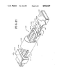
- FIGS. 15-17 A further embodiment of the apparatus and process of the present invention is illustrated in FIGS. 15-17 with this apparatus embodiment being identified by general numerical designation 110.
- the apparatus includes a base or mounting member 112 on which is slidably mounted a capillary tube 114 and on which base is provided a reservoir indicated by general numerical designation 116; in this embodiment the reservoir is comprised of opposed, spaced apart, and upwardly extending members 117 and 118 providing the reservoir or reservoir space 116A therebetween.
- the capillary tube 114 is non-circular in cross-section and is provided with a bore 118 having a non-circular, cross-sectional shape which may be any one of those shown in FIGS. 7-9.
- the capillary tube 114 is secured at its rearward end to a manually operable slide or slide member 136, such as by being secured thereto by a suitable adhesive, and resides slidably in a groove or slot 138 provided in the top surface of the mounting member 112. Further, in this embodiment, the mounting member 112 is provided with a cavity or open chamber 140 which cavity, upon the capillary tube 114 being in the rearward position shown in FIG. 14, resides intermediate the opposed forward end of the capillary tube 114 and the reservoir 116.
- the cavity 140 may receive either the sample containing an analyte of interest or test reagent system, both of which are liquids in this embodiment, and the reservoir 116 may receive the other of the sample and test reagent system; for the purposes of this description, it will be presumed that the liquid test reagent system is placed in the cavity 140, such as by pipetting, and that the sample 130 is placed in the reservoir or reservoir space 116 also by pipetting.
- the slide member 136 will be gripped by the fingers of the operator and moved or advanced forwardly in the direction of the arrow 142 of FIG. 16 to slidably advance the capillary 114 forwardly in the slot 138 until the forward end thereof, as illustrated in FIG.
- the capillary tube 114 may be made of glass, and the mounting member 112 may be made of a suitable plastic such as polystyrene and injection molded into the shape shown in FIGS. 15-17, the mounting member 112 may include a magnifying portion 146 enhancing optical determination of the reaction, it being understood that the turbulent flow provided by capillary attraction to the liquid test reagent system 126 and sample 130 advances them into the capillary tube 114 in the direction of the arrow 147 of FIG.
- the magnifying portion 146 is provided on the mounting member 112 to reside in actual practice substantially over the area or length of reaction between the analyte and test reagent system within the bore 118 of the capillary tube 114.
- FIGS. 18 and 19 a further embodiment of the present invention is illustrated which embodiment is substantially the same as that illustrated in FIGS. 15-17 except that in this embodiment the reservoir 216 is embodied as a capillary tube formed, such as by molding, integrally with the mounting member 212 and, except for the provision of the two cavities 260 and 270 shown disposed on either side of the cavity 240 for receiving either liquid sample containing an analyte of interest or liquid test reagent system.
- the cavity 260 upon the capillary tube 214 being in its rearward position as shown in FIG.
- the cavity 270 resides intermediate the cavity 240 and the reservoir 216 and provides a barrier for preventing either the liquid sample or liquid test reagent system residing in the cavity 240 from being drawn by capillary attraction into the reservoir 216.
- FIG. 20 The apparatus and process alternate embodiments of the present invention illustrated in FIG. 20 have been found to be particularly useful for facilitating reaction between an analyte contained in a liquid sample and a first liquid test reagent system and for facilitating reaction between an admixture of the liquid sample and first liquid test reagent system and a second liquid test reagent system.
- two cavities, 340 and 350 are provided on the mounting member 312 and, upon the capillary tube 314 being in its rearward position (not shown), the cavities 340 and 350 reside intermediate the forward end of the capillary tube 314 and the reservoir 316 and, as may be noted from FIG. 20, the capillary tube 314, cavities 340 and 350, and reservoir 316 are aligned linearly with the first cavity 340 adjacent the forward end of the capillary tube 314 and with the cavity 350 adjacent the reservoir 316.
- the capillary tube 314 is advanced through the cavities 340 and 350.
- the sample to be used is the fertile female's urine, and the analyte to be determined, whose presence usually indicates pregnancy and whose absence usually indicates non-pregnancy, will be hCG (human chorionic gonadotropin); hCG being, as is known, an antigen.
- hCG human chorionic gonadotropin
- the liquid urine sample may be placed in the cavity 340 by pipetting, a suitable liquid antibody reagent to hCG may be placed in the cavity 350 by pipetting, and a suitable liquid reagent containing latex beads coated with hCG antigen may be placed in the reservoir 316 by pipetting.
- the capillary tube 14 will be at its rearward position (not shown in FIG. 20) and will be advanced forwardly to first cause the capillary tube to engage the liquid urine sample contained in cavity 340 to draw such sample by capillary attraction into the bore 318 of the capillary tube.
- the capillary tube will be further advanced into the cavity 315 to cause the liquid antibody reagent to hCG contained therein to be drawn into the capillary tube bore 318 by capillary attraction and to bring the hCG antigen analyte contained in the urine sample into turbulent contact with the antibody to hCG facilitating the above-noted reaction therebetween provided by the present invention which reaction will complex the hCG antibody and the analyte of the urine sample.
- the capillary tube will be advanced farther into the reservoir 316 to cause the liquid test reagent residing containing the latex beads coated with hCG to be drawn into the capillary tube bore 318 and since the antibody reagent contained in cavity 350 was complexed to the hCG antigen contained in the urine sample resulting in no antibody availability, agglutination will not occur and such absence of agglutination will be understood to indicate that the female is pregnant.
- the antibody reagent to hCG contained in the cavity 350 would not be fully complexed upon entry into the capillary tube bore and contacting the urine and hence upon the liquid test reagent system containing latex beads with hCG antigen from the reservoir 316 being drawn into the capillary tube bore 318, the reaction facilitated by the present invention between such antibody and antigen will occur causing agglutination which presence will be understood to indicate that the female is not pregnant.
- FIG. 21 is particularly useful for contemporaneously facilitating an optically determinable reaction between an analyte of interest contained in a sample and an analytical or reaction test reagent system and a control test between the sample and a control or non-reactive test reagent system. It will be understood that the apparatus 410 of FIG. 21 is substantially similar, particularly, to that disclosed in FIGS.
- capillary tubes 414 and 414A are of the same length, disposed substantially parallel and secured to the slide member 436 for sliding advancement therewith and simultaneous entry of the forward ends of the capillary tubes 414 and 414A into the reservoir 416.
- the reservoir 416 will be filled, either by capillary attraction or pipetting as taught above, with a sample containing an analyte of interest (e.g. the above-noted blood serum believed to contain antibodies to the AIDS virus) and an analytical or reactive liquid test reagent system (e.g. the above-noted liquid latex reagent system including latex beads or particles coated with two glycoprotein fractions known to be detectable in the AIDS virus) will be placed in the cavity 440, such as by pipetting, and a control or non-reactive liquid test reagent system (e.g.
- an analyte of interest e.g. the above-noted blood serum believed to contain antibodies to the AIDS virus
- an analytical or reactive liquid test reagent system e.g. the above-noted liquid latex reagent system including latex beads or particles coated with two glycoprotein fractions known to be detectable in the AIDS virus
- a control or non-reactive liquid test reagent system e.g.
- the above-noted liquid latex reagent system including latex beads or particles not coated with the two glycoprotein fractions known to be detectable in the AIDS virus
- the capillary tubes 414 and 414A will be advanced to first engage, respectively, the analytical or reactive liquid test reagent system residing in cavity 440 and the control or non-reactive test reagent system residing in cavity 440A to cause such respective liquid test reagent systems to be drawn by capillary attraction into the capillary tubes 414 and 414A, whereafter upon continued advancement of the slide member 436 and the capillary tubes 414 and 414A the forward ends of the capillary tubes 414 and 414A will be advanced into the reservoir 416 to draw by capillary attraction respective portions of the sample contained therein into the respective capillary tubes.
- reaction between the analyte contained in the sample portion drawn into capillary tube 414 and the analytical or reactive liquid test reagent system will be facilitated, as taught hereinabove, and the sample portion drawn into capillary tube 414A will not react with the control or non-reactive liquid test reagent system.
- the actual agglutination reaction occurring in capillary tube 414 may be viewed, or optically determined, through the magnifying portion 446 of the apparatus 410 and the absence of a reaction in the capillary tube 414A also may be viewed or optically determined through the magnifying portion 446, and thus a visual or optical comparison may be made to establish the validity of the reaction present in capillary tube 414.
- capillary tubes 414 and 414A of apparatus 410 may each be provided with a bore having a non-circular, cross-section of the various embodiments taught hereinabove and disclosed in FIGS. 7-9 for the reasons and advantages also taught hereinabove and that the capillary tubes 414 and 414A may be made of glass facilitating optical determination of a reaction, or non-reaction, occurring therein.
- the slide member 436 may be provided with an inwardly extending groove 475 for receiving in sliding relationship the complementary shaped upwardly extending rib 477 formed on the mounting apparatus 412 to facilitate maintaining the slide member 436, and hence the capillary tubes 414 and 414A secured thereto, in coaxial alignment with the reservoir 416 particularly during advancement as described above.
- the capillary tubes 414 and 414A may be of the same length as shown and described above or, if it is desired to begin either the control test or analytical or reactive test earlier than the other, either of the forward ends of the capillary tubes may be shortened with respect to the other to provide this displacement in time and commencing of the respective tests or reactions.
- the reservoir 416 may be capillary means as shown in FIG. 21 or may be a reservoir provided, for example, by the upwardly extending members illustrated in FIGS. 15-17 providing the reservoir 116 or reservoir space 116A.
- the blood may be provided by a finger prick and the blood may be drawn off directly by capillary attraction by placing the rearward end of the reservoir 16 in contact with droplet of blood produced at the finger prick to a predetermined calibration mark which calibration mark may be provided on the reservoir 16.
- a white background or one of contrasting color to the reaction, may be provided on the top surface of the card or support to enhance optical determination, e.g. human visualization, of a colorimetric reaction test result, for example an enzyme reaction test or enzyme immunoassay reaction test including a chromophore.
- the apparatus and process of the present invention may be used in a variety of test reaction systems, for example the device is particularly useful for, but not limited to, reaction tests using particulate markers, agglutination or agglutination inhibition reaction tests, turbidimetric and nephelometric reaction tests, coagulation, colorimetric and enzyme or enzyme-mediated, luminescent, fluorometric, reaction tests.
- the apparatus and process of the present invention are particularly useful for facilitating analytical reaction tests which require only minimal amounts of the sample and test reagent system, facilitate rapid reactions, provide for easy optical determination, e.g. human visualization, of the reaction results or absence thereof, provide a disposable test apparatus that requires minimal handling and which may be made sufficiently inexpensively that it may be a disposable, provides a non-labor intensive apparatus capable of being employed by individuals not trained in the performance of analytical tests, and provides, as noted above, apparatus wherein a variety of tests may be performed, viz. agglutination or agglutination inhibition, colorimetric, turbidimetric, enzyme mediated and immunoassays, etc..
Landscapes
- Health & Medical Sciences (AREA)
- Immunology (AREA)
- Life Sciences & Earth Sciences (AREA)
- Chemical & Material Sciences (AREA)
- Engineering & Computer Science (AREA)
- Hematology (AREA)
- Biomedical Technology (AREA)
- Molecular Biology (AREA)
- Urology & Nephrology (AREA)
- General Health & Medical Sciences (AREA)
- Analytical Chemistry (AREA)
- Food Science & Technology (AREA)
- General Physics & Mathematics (AREA)
- Medicinal Chemistry (AREA)
- Physics & Mathematics (AREA)
- Cell Biology (AREA)
- Biochemistry (AREA)
- Biotechnology (AREA)
- Microbiology (AREA)
- Pathology (AREA)
- Dispersion Chemistry (AREA)
- Clinical Laboratory Science (AREA)
- Chemical Kinetics & Catalysis (AREA)
- Investigating Or Analysing Biological Materials (AREA)
- Sampling And Sample Adjustment (AREA)
Abstract
Description
R.sub.e = VD/μ=inertial/viscous
Claims (61)
Priority Applications (1)
| Application Number | Priority Date | Filing Date | Title |
|---|---|---|---|
| US07/106,573 US4902629A (en) | 1987-10-06 | 1987-10-06 | Apparatus and processes for facilitating reaction between analyte and test reagent system |
Applications Claiming Priority (1)
| Application Number | Priority Date | Filing Date | Title |
|---|---|---|---|
| US07/106,573 US4902629A (en) | 1987-10-06 | 1987-10-06 | Apparatus and processes for facilitating reaction between analyte and test reagent system |
Publications (1)
| Publication Number | Publication Date |
|---|---|
| US4902629A true US4902629A (en) | 1990-02-20 |
Family
ID=22312157
Family Applications (1)
| Application Number | Title | Priority Date | Filing Date |
|---|---|---|---|
| US07/106,573 Expired - Fee Related US4902629A (en) | 1987-10-06 | 1987-10-06 | Apparatus and processes for facilitating reaction between analyte and test reagent system |
Country Status (1)
| Country | Link |
|---|---|
| US (1) | US4902629A (en) |
Cited By (28)
| Publication number | Priority date | Publication date | Assignee | Title |
|---|---|---|---|---|
| WO1991013998A1 (en) * | 1990-03-12 | 1991-09-19 | Biosite Diagnostics, Inc. | Bioassay device with non-absorbent textured capillary surface |
| US5174162A (en) * | 1989-07-10 | 1992-12-29 | Hitachi, Ltd. | Pipetter, pipette tube, sample analyzing apparatus including them and method of mixing and pipetting liquids |
| US5188965A (en) * | 1991-03-18 | 1993-02-23 | Difco Laboratories | Reagent source for chemiluminescent reactions, test kit, and method for use |
| US5324413A (en) * | 1989-03-06 | 1994-06-28 | Hewlett-Packard Company | Electrophoresis capillary with dispersion-inhibiting cross-section |
| US5399316A (en) * | 1992-03-13 | 1995-03-21 | Olympus Optical Co., Ltd. | Reaction vessel for conducting an immunological assay |
| US5492674A (en) * | 1995-03-17 | 1996-02-20 | Boehringer Mannheim Corporation | Evanescent wave immunoassay system |
| US5609822A (en) * | 1995-07-07 | 1997-03-11 | Ciba Corning Diagnostics Corp. | Reagent handling system and reagent pack for use therein |
| US5620657A (en) * | 1989-11-27 | 1997-04-15 | Behringwerke Ag | Device and method for completing a fluidic circuit |
| US5877028A (en) | 1991-05-29 | 1999-03-02 | Smithkline Diagnostics, Inc. | Immunochromatographic assay device |
| US5879951A (en) | 1997-01-29 | 1999-03-09 | Smithkline Diagnostics, Inc. | Opposable-element assay device employing unidirectional flow |
| US5939252A (en) | 1997-05-09 | 1999-08-17 | Lennon; Donald J. | Detachable-element assay device |
| US5998220A (en) | 1991-05-29 | 1999-12-07 | Beckman Coulter, Inc. | Opposable-element assay devices, kits, and methods employing them |
| US6066300A (en) * | 1995-07-07 | 2000-05-23 | Bayer Corporation | Reagent handling system and configurable vial carrier for use therein |
| USD432244S (en) * | 1998-04-20 | 2000-10-17 | Adeza Biomedical Corporation | Device for encasing an assay test strip |
| USD434153S (en) * | 1998-04-20 | 2000-11-21 | Adeza Biomedical Corporation | Point of care analyte detector system |
| US6168956B1 (en) | 1991-05-29 | 2001-01-02 | Beckman Coulter, Inc. | Multiple component chromatographic assay device |
| US6267722B1 (en) | 1998-02-03 | 2001-07-31 | Adeza Biomedical Corporation | Point of care diagnostic systems |
| US6312888B1 (en) | 1998-06-10 | 2001-11-06 | Abbott Laboratories | Diagnostic assay for a sample of biological fluid |
| US6394952B1 (en) | 1998-02-03 | 2002-05-28 | Adeza Biomedical Corporation | Point of care diagnostic systems |
| US20030124509A1 (en) * | 1999-06-03 | 2003-07-03 | Kenis Paul J.A. | Laminar flow patterning and articles made thereby |
| US6653089B2 (en) | 2000-09-18 | 2003-11-25 | President And Fellows Of Harvard College | Differential treatment of selected parts of a single cell with different fluid components |
| US20040087631A1 (en) * | 2002-03-04 | 2004-05-06 | Bacopoulos Nicholas G. | Methods of treating cancer with HDAC inhibitors |
| US6740293B1 (en) | 2001-07-17 | 2004-05-25 | Biotech Atlantic, Inc. | Housing for test strip device and test strip therefor |
| JP2006300944A (en) * | 2005-04-15 | 2006-11-02 | Boehringer Ingelheim Microparts Gmbh | Device and method for operating liquid |
| US20070056384A1 (en) * | 2003-06-09 | 2007-03-15 | Exxon Mobil Upstream Resarch Company Cor-Urc-Sw348 | Method and apparatus for fluid flow testing |
| US20150238957A1 (en) * | 2011-03-15 | 2015-08-27 | Carclo Technical Plastics Limited | Capillary fluid flow control |
| US10258981B2 (en) * | 2012-12-05 | 2019-04-16 | Forward Biotech, Inc. | Dispensed liquid measurement device |
| US11389096B2 (en) * | 2016-09-10 | 2022-07-19 | Ecole Polytechnique Federale De Lausanne (Epfl) | Bio-fluid collection and sensing device, system and method |
Citations (4)
| Publication number | Priority date | Publication date | Assignee | Title |
|---|---|---|---|---|
| US4058146A (en) * | 1975-07-11 | 1977-11-15 | Dynatech Laboratories Incorporated | Method and apparatus for transferring liquid |
| US4088448A (en) * | 1975-09-29 | 1978-05-09 | Lilja Jan Evert | Apparatus for sampling, mixing the sample with a reagent and making particularly optical analyses |
| US4585623A (en) * | 1984-02-27 | 1986-04-29 | Allelix Inc. | Device for performing quantitative chemical and immunochemical assays |
| US4596695A (en) * | 1984-09-10 | 1986-06-24 | Cottingham Hugh V | Agglutinographic reaction chamber |
-
1987
- 1987-10-06 US US07/106,573 patent/US4902629A/en not_active Expired - Fee Related
Patent Citations (4)
| Publication number | Priority date | Publication date | Assignee | Title |
|---|---|---|---|---|
| US4058146A (en) * | 1975-07-11 | 1977-11-15 | Dynatech Laboratories Incorporated | Method and apparatus for transferring liquid |
| US4088448A (en) * | 1975-09-29 | 1978-05-09 | Lilja Jan Evert | Apparatus for sampling, mixing the sample with a reagent and making particularly optical analyses |
| US4585623A (en) * | 1984-02-27 | 1986-04-29 | Allelix Inc. | Device for performing quantitative chemical and immunochemical assays |
| US4596695A (en) * | 1984-09-10 | 1986-06-24 | Cottingham Hugh V | Agglutinographic reaction chamber |
Cited By (44)
| Publication number | Priority date | Publication date | Assignee | Title |
|---|---|---|---|---|
| US5324413A (en) * | 1989-03-06 | 1994-06-28 | Hewlett-Packard Company | Electrophoresis capillary with dispersion-inhibiting cross-section |
| US5174162A (en) * | 1989-07-10 | 1992-12-29 | Hitachi, Ltd. | Pipetter, pipette tube, sample analyzing apparatus including them and method of mixing and pipetting liquids |
| US5620657A (en) * | 1989-11-27 | 1997-04-15 | Behringwerke Ag | Device and method for completing a fluidic circuit |
| US5622870A (en) * | 1989-11-27 | 1997-04-22 | Behringwerke Ag | Device and method for completing a fluidic circuit |
| WO1991013998A1 (en) * | 1990-03-12 | 1991-09-19 | Biosite Diagnostics, Inc. | Bioassay device with non-absorbent textured capillary surface |
| US5188965A (en) * | 1991-03-18 | 1993-02-23 | Difco Laboratories | Reagent source for chemiluminescent reactions, test kit, and method for use |
| US5877028A (en) | 1991-05-29 | 1999-03-02 | Smithkline Diagnostics, Inc. | Immunochromatographic assay device |
| US6168956B1 (en) | 1991-05-29 | 2001-01-02 | Beckman Coulter, Inc. | Multiple component chromatographic assay device |
| US6017767A (en) | 1991-05-29 | 2000-01-25 | Beckman Coulter, Inc. | Assay device |
| US5998220A (en) | 1991-05-29 | 1999-12-07 | Beckman Coulter, Inc. | Opposable-element assay devices, kits, and methods employing them |
| US5399316A (en) * | 1992-03-13 | 1995-03-21 | Olympus Optical Co., Ltd. | Reaction vessel for conducting an immunological assay |
| WO1996029589A1 (en) * | 1995-03-17 | 1996-09-26 | Boehringer Mannheim Corporation | Evanescent wave immunoassay system |
| US5492674A (en) * | 1995-03-17 | 1996-02-20 | Boehringer Mannheim Corporation | Evanescent wave immunoassay system |
| US5788928A (en) * | 1995-07-07 | 1998-08-04 | Chiron Diagnostics Corporation | Reagent handling system and reagent pack for use therein |
| US5609822A (en) * | 1995-07-07 | 1997-03-11 | Ciba Corning Diagnostics Corp. | Reagent handling system and reagent pack for use therein |
| US6066300A (en) * | 1995-07-07 | 2000-05-23 | Bayer Corporation | Reagent handling system and configurable vial carrier for use therein |
| US5879951A (en) | 1997-01-29 | 1999-03-09 | Smithkline Diagnostics, Inc. | Opposable-element assay device employing unidirectional flow |
| US5939252A (en) | 1997-05-09 | 1999-08-17 | Lennon; Donald J. | Detachable-element assay device |
| US6394952B1 (en) | 1998-02-03 | 2002-05-28 | Adeza Biomedical Corporation | Point of care diagnostic systems |
| US20040241752A1 (en) * | 1998-02-03 | 2004-12-02 | Anderson Emory V. | Point of care diagnostic systems |
| US6267722B1 (en) | 1998-02-03 | 2001-07-31 | Adeza Biomedical Corporation | Point of care diagnostic systems |
| US20060014302A1 (en) * | 1998-02-03 | 2006-01-19 | Martinez Ricardo R | Point of care diagnostic systems |
| US7270970B2 (en) | 1998-02-03 | 2007-09-18 | Adeza Biomedical Corporation | Point of care diagnostic systems |
| US20060008923A1 (en) * | 1998-02-03 | 2006-01-12 | Anderson Emory V | Point of care diagnostic systems |
| US6936476B1 (en) | 1998-02-03 | 2005-08-30 | Adeza Biomedical Corporation | Point of care diagnostic systems |
| US6867051B1 (en) | 1998-02-03 | 2005-03-15 | Adeza Biomedical, Inc. | Point of care diagnostic systems |
| USD432244S (en) * | 1998-04-20 | 2000-10-17 | Adeza Biomedical Corporation | Device for encasing an assay test strip |
| USD434153S (en) * | 1998-04-20 | 2000-11-21 | Adeza Biomedical Corporation | Point of care analyte detector system |
| US6312888B1 (en) | 1998-06-10 | 2001-11-06 | Abbott Laboratories | Diagnostic assay for a sample of biological fluid |
| US20030124509A1 (en) * | 1999-06-03 | 2003-07-03 | Kenis Paul J.A. | Laminar flow patterning and articles made thereby |
| US6653089B2 (en) | 2000-09-18 | 2003-11-25 | President And Fellows Of Harvard College | Differential treatment of selected parts of a single cell with different fluid components |
| US6740293B1 (en) | 2001-07-17 | 2004-05-25 | Biotech Atlantic, Inc. | Housing for test strip device and test strip therefor |
| US20040087631A1 (en) * | 2002-03-04 | 2004-05-06 | Bacopoulos Nicholas G. | Methods of treating cancer with HDAC inhibitors |
| US20070056384A1 (en) * | 2003-06-09 | 2007-03-15 | Exxon Mobil Upstream Resarch Company Cor-Urc-Sw348 | Method and apparatus for fluid flow testing |
| US7540200B2 (en) * | 2003-06-09 | 2009-06-02 | Exxonmobil Upstream Research Company | Method and apparatus for fluid flow testing |
| US20060249387A1 (en) * | 2005-04-15 | 2006-11-09 | Boehringer Ingelheim Microparts Gmbh | Device and process for manipulation of a liquid |
| JP2006300944A (en) * | 2005-04-15 | 2006-11-02 | Boehringer Ingelheim Microparts Gmbh | Device and method for operating liquid |
| EP1714698A3 (en) * | 2005-04-15 | 2008-07-16 | Boehringer Ingelheim microParts GmbH | Device and method for handling liquids |
| US7655189B2 (en) | 2005-04-15 | 2010-02-02 | Boehringer Ingelheim Microparts Gmbh | Device and process for manipulation of a liquid |
| CN1865714B (en) * | 2005-04-15 | 2010-12-08 | 泊灵格英格尔海姆微部件有限责任公司 | Device and method for handling liquids |
| US20150238957A1 (en) * | 2011-03-15 | 2015-08-27 | Carclo Technical Plastics Limited | Capillary fluid flow control |
| US9352316B2 (en) * | 2011-03-15 | 2016-05-31 | Carclo Technical Plastics Limited | Capillary fluid flow control |
| US10258981B2 (en) * | 2012-12-05 | 2019-04-16 | Forward Biotech, Inc. | Dispensed liquid measurement device |
| US11389096B2 (en) * | 2016-09-10 | 2022-07-19 | Ecole Polytechnique Federale De Lausanne (Epfl) | Bio-fluid collection and sensing device, system and method |
Similar Documents
| Publication | Publication Date | Title |
|---|---|---|
| US4902629A (en) | Apparatus and processes for facilitating reaction between analyte and test reagent system | |
| US6277641B1 (en) | Methods for analyzing the presence and concentration of multiple analytes using a diffusion-based chemical sensor | |
| US5225163A (en) | Reaction apparatus employing gravitational flow | |
| CA1300497C (en) | Agglutinographic chamber | |
| US6468807B1 (en) | Mixing method | |
| DE3853457T2 (en) | DEVICE AND METHOD FOR ACCURACY, FAST AND SIMPLE PERFORMANCE OF A PROTHROMBIN TEST. | |
| CN1111732C (en) | Capillary microcuvette | |
| EP0607170B1 (en) | Method and device for metering of fluid samples | |
| US7271007B2 (en) | Microscale diffusion immunoassay | |
| US5500187A (en) | Disposable optical agglutination assay device and method for use | |
| US6488896B2 (en) | Microfluidic analysis cartridge | |
| US6297061B1 (en) | Simultaneous particle separation and chemical reaction | |
| CA2195875C (en) | Devices and methods utilizing arrays of structures for analyte capture | |
| US6454945B1 (en) | Microfabricated devices and methods | |
| EP0890094B1 (en) | Microfabricated diffusion-based chemical sensor | |
| US5788863A (en) | Apparatus and method for conducting an assay using reverse flow through a membrane | |
| KR101140439B1 (en) | Reducing working fluid dilution in liquid systems | |
| US5019351A (en) | Agglutination reaction slide | |
| US20020090644A1 (en) | Microscale diffusion immunoassay | |
| JP4471687B2 (en) | Biochemical analysis method and biochemical analyzer | |
| US20060079003A1 (en) | Apparatus and method for a precision flow assay | |
| US10473651B2 (en) | Method for determining agglutination | |
| Weigl et al. | Simultaneous Self-Referencing Analyte Determination in Complex Sample Solutions Using Microfabricated Flow Structures (T-Sensors™) | |
| WO2006042332A2 (en) | Apparatus and method for a precision flow assay |
Legal Events
| Date | Code | Title | Description |
|---|---|---|---|
| AS | Assignment |
Owner name: PERSONAL DIAGNOSTICS, INC.,NEW JERSEY Free format text: ASSIGNMENT OF ASSIGNORS INTEREST;ASSIGNORS:MESEROL, PETER M.;BERNSTEIN, PHILIP;PRODELL, RITA C.;AND OTHERS;REEL/FRAME:004774/0764 Effective date: 19871001 Owner name: PERSONAL DIAGNOSTICS, INC., 628 ROUTE 10, WHIPPANY Free format text: ASSIGNMENT OF ASSIGNORS INTEREST.;ASSIGNORS:MESEROL, PETER M.;BERNSTEIN, PHILIP;PRODELL, RITA C.;AND OTHERS;REEL/FRAME:004774/0764 Effective date: 19871001 |
|
| AS | Assignment |
Owner name: CORESTATES NEW JERSEY NATIONAL BANK, NEW JERSEY Free format text: SECURITY INTEREST;ASSIGNOR:PERSONAL DIAGNOSTICS, INCORPORATED;REEL/FRAME:006535/0292 Effective date: 19930317 |
|
| REMI | Maintenance fee reminder mailed | ||
| LAPS | Lapse for failure to pay maintenance fees | ||
| FP | Lapsed due to failure to pay maintenance fee |
Effective date: 19930220 |
|
| STCH | Information on status: patent discontinuation |
Free format text: PATENT EXPIRED DUE TO NONPAYMENT OF MAINTENANCE FEES UNDER 37 CFR 1.362 |