US4867346A - Dispenser for reactive chemicals - Google Patents
Dispenser for reactive chemicals Download PDFInfo
- Publication number
- US4867346A US4867346A US07/101,412 US10141287A US4867346A US 4867346 A US4867346 A US 4867346A US 10141287 A US10141287 A US 10141287A US 4867346 A US4867346 A US 4867346A
- Authority
- US
- United States
- Prior art keywords
- rod
- purging
- core
- mixing chamber
- bore
- Prior art date
- Legal status (The legal status is an assumption and is not a legal conclusion. Google has not performed a legal analysis and makes no representation as to the accuracy of the status listed.)
- Expired - Fee Related
Links
Images


Classifications
-
- B—PERFORMING OPERATIONS; TRANSPORTING
- B67—OPENING, CLOSING OR CLEANING BOTTLES, JARS OR SIMILAR CONTAINERS; LIQUID HANDLING
- B67D—DISPENSING, DELIVERING OR TRANSFERRING LIQUIDS, NOT OTHERWISE PROVIDED FOR
- B67D7/00—Apparatus or devices for transferring liquids from bulk storage containers or reservoirs into vehicles or into portable containers, e.g. for retail sale purposes
- B67D7/06—Details or accessories
- B67D7/74—Devices for mixing two or more different liquids to be transferred
-
- B—PERFORMING OPERATIONS; TRANSPORTING
- B29—WORKING OF PLASTICS; WORKING OF SUBSTANCES IN A PLASTIC STATE IN GENERAL
- B29B—PREPARATION OR PRETREATMENT OF THE MATERIAL TO BE SHAPED; MAKING GRANULES OR PREFORMS; RECOVERY OF PLASTICS OR OTHER CONSTITUENTS OF WASTE MATERIAL CONTAINING PLASTICS
- B29B7/00—Mixing; Kneading
- B29B7/74—Mixing; Kneading using other mixers or combinations of mixers, e.g. of dissimilar mixers ; Plant
- B29B7/76—Mixers with stream-impingement mixing head
- B29B7/7663—Mixers with stream-impingement mixing head the mixing head having an outlet tube with a reciprocating plunger, e.g. with the jets impinging in the tube
- B29B7/7678—Mixers with stream-impingement mixing head the mixing head having an outlet tube with a reciprocating plunger, e.g. with the jets impinging in the tube of the gun type, i.e. hand-held units
Definitions
- This invention relates generally to apparatus for mixing and dispensing a plurality of reactive chemicals, and in particular to an apparatus for mixing and dispensing polyurethane precursor chemicals used to make polyurethane foam and coatings.
- Polyurethane foam can be used in a variety of applications, including insulation and foam-in-place cushioned packaging material.
- the fast reaction and setting of the chemicals to form the polyurethane foam is highly desirable from the standpoint of high production rates of the foam, but reaction of the chemicals inside the dispensing equipment can clog and jam the internal parts of the dispensing equipment, rendering the equipment inoperative.
- a type of polyurethane foam dispensing equipment in wide use is exemplified in U.S. Pat. No. 3,263,928.
- the device disclosed in this patent includes a mixing chamber assembly having a polytetrafluoroethylene (available as "Teflon” from DuPont Corporation) core circumferentially and axially contained within a metallic housing.
- Teflon core has an axial bore therethrough with individual inlets therein for the injection of the reactive chemicals from respective sources of supply into the bore and a valving rod reciprocally movable within the bore.
- the Teflon core is maintained under a compressive force by a threaded nut disposed at the rear of the mixing chamber core to keep an interference fit between the valving rod and the Teflon core to maintain proper sealing of the valving rod with the inlets.
- the valving rod is connected to an air piston which is actuated by means of a trigger.
- the trigger When the trigger is depressed, the valving rod is reciprocated back to uncover the inlets, thereby allowing entry of the reactive chemicals into the bore for mixing and dispensing out the front of the bore.
- the rod After the desired quantity of the mixture has been dispensed, the rod is reciprocated forward to close off the ports to prevent further entry of the reactive chemicals into the bore.
- the valving rod is then moved still forward to the end of the bore so as purge any mixed chemicals which remain in the mixing chamber bore.
- the jamming may be so serious as to require removal and replacement of the Teflon core from the housing, which is a time consuming and laborious process requiring special equipment. During such repair or replacement, the apparatus is unusable. Furthermore, the solvent itself is toxic.
- U.S. Pat. Nos. 4,469,251 and 4,568,003 disclose a dispensing device having a detachable mixing chamber assembly.
- the mixing chamber assembly has a Teflon core having a bore and a valving rod in an interference fit in the bore, similar in function and operation to the device disclosed in U.S. Pat. No. 3,263,928.
- the Teflon core is axially and circumferentially retained in a nondeformable housing, which is also part of the detachable mixing chamber assembly. This housing axially and radially contains and compresses the Teflon core to maintain the interference fit.
- Belleville spring washers are also provided at one end of the housing to maintain the Teflon under a compressive force. This, it is said, maintains the interference fit between the valving rod and the bore so as to maintain an effective seal between the valve and the bore to prevent leakage.
- These patents further teach use of nondeformable inserts in the inlets to maintain the shape of the inlets during use. However, jamming may still occur, and in this event, the mixing chamber, and hence the device, becomes unusable.
- the devices disclosed in U.S. Pat. Nos. 4,469,251 and 4,568,003 have two separable portions.
- One portion includes a mixing chamber assembly, including the nondeformable housing, Teflon core, nondeformable inserts, valving rod and Belleville washers; and another portion includes means for reciprocating the valving rod.
- the mixing chamber assembly becomes jammed or otherwise fails to function, the entire mixing chamber assembly, including the nondeformable housing, Teflon core, nondeformable inserts, valving rod and Belleville washers, is removed from the other portion of the apparatus and replaced with a fresh assembly.
- the relatively high compression necessary to maintain sealing of the valving rod in the Teflon core increases the friction between the valving rod and the Teflon core, and thus the force required to reciprocate the valving rod in the bore.
- the compression on the core has a tendency to cause the nondeformable inserts in the inlets to back away from the rod to the extent permitted by the nondeformable housing. This can potentially allow the Teflon material of the core itself to extrude underneath the discharge end of the insert to occlude the inlets.
- Teflon is also a material which exhibits a tendency to "cold-flow". Thus, Tefon when placed under a compressive force will continue to deform over time.
- the tight compressive force necessary between the mixing chamber core and the associated valving rod has a tendency to compress the Teflon radially inwardly. In time and after a number of valve rod reciprocations, the inner surface of the core is shaved somewhat, destroying the integrity of the tight interference fit.
- the mixing chamber assembly with its non-deformable housing, Belleville washer assembly for maintaining the Teflon core under compression, Teflon core, nondeformable inserts and valving rod is relatively expensive. Discarding the entire mixing chamber assembly is undesirable because of the expense, particularly since the failure is usually confined to only the Teflon core itself and valving rod (which are themselves inexpensive). However, because the Teflon core is tightly contained within the circumferential housing, removal and replacement of the Teflon core and valving rod alone from the housing is difficult and requires special equipment. Still further, the mixing chamber has a limited life, and there is no means of determining when the mixing chamber has nearly reached the end of its useful life. The only way to determine when to replace the mixing chamber assembly is to wait until a failure of some kind, such as jamming or failure to produce acceptable foam, occurs. This is undesirable since failures of any kind occur as unpredictable times and can have costly results.
- a mixing and dispensing apparatus for mutually reactive chemicals which includes a mixing chamber having a core of inexpensive monolithic design with a reciprocal purging rod therethrough, which core and purging rod are readily detachable as a unit from the remainder of the apparatus.
- a still further object of the invention is to provide a mixing chamber and dispensing apparatus for use with reactive chemicals which does not require use of a solvent at all.
- a yet further object of the invention is to provide a visible indication of the amount of useful life remaining for the mixing chamber.
- an apparatus for mixing and dispensing first and second mutually reactive chemicals which has a first body portion and a second body portion.
- the first body portion includes a mixing chamber having a front end, a rear end, a longitudinal bore extending completely therethrough, first and second inlets extending into the bore and positioned between the front end and the rear end, each of which have an entrance end and a discharge end.
- the first body portion further includes a purging rod disposed within the bore. This rod has a front end and a rearward end and is reciprocal between an extended position wherein the front end of the purging rod extends substantially to the front end of the mixing chamber and a retracted position wherein the front end of the purging rod is retracted rearward of the first and second inlet openings.
- the second body portion of the apparatus includes first and second conduits for respectively conducting the first and second chemicals.
- Each of the first and second conduits has entrance means and exit means for its respective chemical.
- the entrance means of each conduit includes means for connection to its respective source of supply of the chemicals and the exit means includes means for sealably and readily detachably connecting the exit means to the entrance end of an inlet.
- First and second valve means are respectively disposed in the first and second conduit means.
- the second body portion of the apparatus also includes means responsive to the position of the purging rod for opening the first and second valve means upon retraction of the purging rod to a retracted position at a position where the front end of the purging rod is rearward of at least a portion of both of the first and second inlets, means responsive to the position of the purging rod for closing the first and second valve means to close the valves upon extension of the purging rod from the retracted position when the front end of the purging rod is still rearward of at least a portion of both of the first and second inlets, and means for maintaining the first and second valves in the closed condition when the front end of the purging rod is fully forward of the first and second inlets.
- the second body portion further includes suitable means for reciprocating the purging rod between the retracted position and the extended position.
- the apparatus further includes means which are accessible from the outside of the apparatus without disassembly of the apparatus for detachably connecting the purging rod to the reciprocating means and means accessible from the outside of the apparatus without disassembly for detachably connecting the mixing chamber to the second body portion are further provided so that, when the purging rod is disconnected from the reciprocating means, the entire first body portion including both the mixing chamber and the purging rod may be readily detached as a unit from the second body portion.
- the mixing chamber is constructed of a substantially monolithic piece of deformable material.
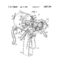
- FIG. 1 is an isometric view of a mixing and dispensing apparatus constructed in accordance with one embodiment of the invention
- FIG. 2 is a cross-sectional view taken along the line 2--2 of FIG. 1 showing the internal arrangement of the components of the mixing and dispensing apparatus;
- FIG. 3 is a detailed cross-sectional view taken along the line 3--3 of FIG. 1 showing the construction of a valve constructed in accordance with one embodiment of the invention
- FIG. 4 is a cross-sectional view taken along the line 4--4 of FIG. 2 showing the arrangement of the valves and mixing chamber;
- FIG. 5 is a cross-sectional view taken along the line 5--5 of FIG. 2 showing a portion of the conduits upstream of the valves;
- FIG. 6 is a cross-sectional view taken along the line 6--6 of FIG. 4 showing the arrangement of the valves with respect to the conduits and the mixing chamber;
- FIG. 7 is a cross-sectional view of one embodiment of the mixing and dispensing apparatus of the present invention, showing one means for removal of the mixing chamber and purging rod from the remainder of the apparatus;
- FIG. 8 is a cross-sectional view of one of the valves of the mixing and dispensing apparatus in the open position
- FIG. 9 is an isometric vie of a mixing chamber core and purging rod constructed in accordance with the present invention showing an alternate means of detachable connection of the purging rod to the piston rod of the apparatus;
- FIG. 10 is a partial sectional view of the alternate means of attachment of the purging rod to the reciprocating portion of the apparatus.
- FIG. 11 is a sectional view of the alternate means of connection of the purging rod to the reciprocating portion of the apparatus, taken along the line 11--11 of FIG. 10;
- FIG. 12 is a cross-sectional view of an embodiment of the present invention having a scraper ring behind the mixing chamber.
- FIGS. 1 and 6 a mixing and dispensing apparatus 10 constructed in accordance with one embodiment of the present invention is illustrated.
- the apparatus 10 includes a reciprocating driver portion 100, a chemical valving portion 500, and a mixing chamber portion 300.
- the reciprocating driver portion 100 includes a handle 101 which may be readily grasped by an operator.
- Handle 101 includes a connection 105 for ahose 110 leading to a source of compressed gas, such as air.
- a trigger 115 is hingeably attached to the handle by means of hinge pin 120.
- Trigger 115 presses on the exposed end of air valve 125, which controls motion of the air in a manner to be described further in this disclosure.
- Reciprocating driver portion 100 further includes an air cylinder 130 with a cylindrical bore 131.
- the cylinder 130 has a front cover 140 and a rear cover 145 both of which are maintained relatively airtight with respect to cylinder 130 by means of 0-ring seals 150.
- a piston rod 155 is connected to piston 135 and extends through front cover 140 towards the front of the apparatus. Piston rod 140 is sealed against air leakage where it passes through the front cover by means of an 0-ring seal160.
- a valve actuating yoke 165 is attached to the external end of the piston rod 155 and moves with it.
- compressed air supplied by means of hose 110 enters the rear of handle 101 and then to a sliding spool valve 170.
- valve 170 When trigger 115 is not depressed, the pressure of the air from hose 110 urges valve 170 forwardly so that seal 175 passes in front of passageway 180 and seal 185 passes in front of passageway 180 leading to the portion of the air cylinder rearward of air piston 135.
- the rear portion of spool valve 170 is hollow, permitting passage of compressed air through the hollow section and out into the front section of the valve through ports 190.
- compressed air then passes through passageway 180 rearwardly ofthe piston, forcing the piston forward, while simultaneously opening exhaust passageway 195 to permit exit of air from between the piston and the front cover.
- the mixing chamber portion of one embodiment of the present invention includes core 301, preferably formed of deformable material, with a longitudinal bore 302 through it from the front end to the rear end of thecore.
- Core 301 is preferably constructed of an essentially monolithic pieceof Teflon or similar material.
- core 301 is a parallelepiped, with a generally square cross-section.
- Core 301 includes two inlets 305 and 305' extending from the exterior surface of core 301 generally radially through the wall of the core into the longitudinal bore. Each of these inlets is oriented generally perpendicular with an exterior face of the Teflon core. Because the inletsare perpendicular to a flat face, forming the inlets in the core is very simple. And, because the core has a generally square cross-section, and the inlets are on adjacent faces, the inlets are offset from each other by90°. Offsetting the inlets by this amount is believed to assist in prevention of clogging of the inlets.
- inlets 305 and 305' to the mixing chamber are lined with non-deformable liners 310 and 310' to help retain their shape and size.
- a purging rod 315 is slidably received into bore 302 and reciprocal within it from an extended position where the front end of purging rod 315 extends to substantially the front end of the mixing chamber core 301 and a retracted position where the front end of the purging rod is rearward ofinlets 305 and 305'.
- a scraper ring 320 is provided in a rear scraper cavity 322 at the rear of the mixing chamber.
- Cavity 322 is preferably a longitudinal bore substantially larger than the diameter of the purging rod and substantially coaxial it.
- the scraper ring has a bore slightly smaller than the diameter of the purging rod so that there is an interference fit between them, and is preferably made from a sturdy material such as steel.
- the scraper ring has an outside diameter sized so that it fits closely in the longitudinal bore but can slide longitudinally back and forth in the bore.
- any solidified material which has adhered to the purging rod will be scraped off the rod by the scraper ringand deposited in the cavity 322 in front of the scraper ring into space 323, thus helping to prevent accumulation of material on the purging rod.
- the scraped-off material will begin to build up in space 323 in front of the scraper ring. This build-upof material causes a periodic cocking of the scraper ring and the back-up washer, gradually moving them rearwardly as the dispenser is used and the build-up continues.
- the position of the back-up washer provides a visible indication of the amountof build-up, and hence the condition of the mixing chamber.
- scraper ring 320 can be placed rearward of the mixing chamber.
- grooves 325 and 330 are provided, respectively, in the mixing chamber support surface 335 and a retainer 340 to hold the scraper ring.
- the rear end of the purging rod 315 is detachably connected to the piston rod 155.
- the rear end of the purging rod includes a mushroomed portion 345 which detachably fits into a slot 350 formed in theend of piston rod 155, as depicted in FIGS. 9 and 10.
- purging rod 315 can be readily removed generally non-axially to the piston rod by lifting the mushroomed end out of the slot 350 at the same time the mixing chambercore 301 is removed, without the need for prior removal of the purging rod from the mixing chamber core.
- the purging rod and mixing chamber core can be removed and replaced together as one replaceable unit.
- the purging rod is connected as depicted in FIGS. 1,2 and 7.
- piston rod 155 is hollow and extends through rear cover 145 of the air cylinder, where it is sealedagainst air leakage by seal 350, as well as through the front cover in the manner already described.
- the purging rod is of extended length, and has a flattened connection tongue 355 at its rear end.
- the rear of piston rod 155 includes a rotatable connection nut 360 with a slot 365.
- the purging rod extends through the hollow piston rod to the rear of the piston rod until the connection tongue 355 extends throughslot 365 in the connection nut. Rotating the nut 90° secures the connection tongue to the connection nut.
- the nut is rotated back 90°.
- the purging rod can be slid through the hollow piston rod in a generally forwardly direction until it is clear of the piston rod. Because the purging rod has an extended length, and is supported in the hollow piston rod, misalignments of the purging rod have a lesser tendency to rock or dislodge the mixing chamber. This helps to improve the life of the mixing chamber.
- the mixing chamber core itself may be removed from the remainder of the apparatus with the purging rod therein. Because the core is very inexpensive, repairor rebuilding is unnecessary. When the mixing chamber becomes unusable for any reason, the core, along with its purging rod is simply discarded, and replaced with a new core and purging rod.
- mixing chamber core 301 itself is preferably directly supported by support surfaces 335.
- the inlets of the core align with respective exit openings 370 and 370' of thechemical conduits of the chemical valving portion, and are sealed from the outside by means of seals 375 and 375', which are preferably made from Nylon, or other suitable material.
- Retainer 340 is attached to the remainder of the front of the apparatus by means of bolts 390, although other means of attachment, such as a hinge could be equally well employed.
- the retainer 340 includes two teeth 395 which enter the deformable core, thus preventing axial movement when the retainer is in place.
- the purging rod fits within the bore of the mixing chamber core with substantially no clearance. It is not necessary or desirable to have a significant interference fit between the purging rod and the mixing chamber core, because the purging rod does not need to form a pressure seal against the inlets, and an interference fit increases the force required to move the purging rod. In any event, because Teflon has a tendency to cold-flow, any interference fit which may unintentionally be present is readily dissipated. In addition, an unnecessarily tight interference fit would have a tendency to cause the Teflon to cold-flow.
- the chemical valving portion 500 of the apparatus includes connections 501 and 501' which receive the connecting end 505 and 505', respectively, of hoses 510 and 510', which are respectively connected to sources of supply of the chemicals to be mixed.
- valve means for controlling the flow of each of the chemicals into themixing chamber will be described. Only one of the respective valve means will be described, however, since the depicted valves for each of the respective chemicals are identical.
- Needle valve 520 has a stem 525 extending to the exterior of the conduit.
- the stem 525 has an exterior actuating end 530, and is sealed against leakage to the outside of the apparatus by means of a seal 535.
- the exterior actuating end 530 of the valve stem 525 passes through a hole 545in yoke 165, and includes a threaded portion 535 with a nut 540 thereon which is larger than the hole 545 in the yoke.
- the nut 540 can be screwed in or out to some degree.
- the nut 540 is adjusted so that both valves open approximately simultaneously.
- valves can be attached to each other by means of a collar.
- the piston rod would be connected to the collar by means of a lost motion linkage, such as a shaft having an enlarged end passing through a hole in the collar, with a space provided between the enlarged end and the collar so that the piston rod would have to be retracted for some distance before it met the collar.
- a lost motion linkage such as a shaft having an enlarged end passing through a hole in the collar, with a space provided between the enlarged end and the collar so that the piston rod would have to be retracted for some distance before it met the collar.
- the operation of this embodiment would be mechanically essentially the same as the depicted embodiment.
- Seal 535 is preferably made of Teflon, or other material which will not be chemically degraded by the chemical. Needle valve 520 has a conical portion 550 which fits into a seat 555.
- the seat 555 is preferably made of a material which will not be chemically degraded by the chemical being handled, and which will also effectively form a pressure tight seal, such as Teflon.
- the conduit On the downstream side of seat 555, the conduit includes a filter screen 560 through which the chemical must pass on its way towards the mixing chamber.
- the screen 560 is built into a screen retainer housing 565 which is threadably inserted into the front of the housing by means of threaded nut 570. After passing through the filter screen 560, chemical passes through the exit of the conduit in the support face 335.
- FIG. 2 depicts a mixing and dispensing apparatus constructed in accordancewith one embodiment of the invention with the purging rod in the fully forward position so that the front of the purging rod is substantially at the front end of the mixing chamber core, which is the position that the purging rod 315 would take when the trigger 115 is not depressed. In this position, the yoke is clear of nut 540.
- a spring 580 behind the conical nose 550 of the needle valve urges the cone of the needle valve into the seat 555 to form a pressure tight seal, prohibiting fluid flow through the conduit.
- the purging rod 315 is connected to the piston rod 155 and moves directly with it. Since both the purging rod and the yoke are mechanicallylinked to the piston rod 155, the purging rod and the yoke will reciprocateback and forth together.
- the air valve moves rearwardly, compressed air flows to the front of the piston 135, forcing it rearwardly, and in turn retracting the yoke and the purging rod.
- the valve 580 will remainin the closed position.
- the yoke 165 has been moved rearwardly by thepiston rod 155 a sufficient distance to use up the space between the yoke and nut 540, the yoke 165 will contact the nut 540.
- valve 580 Upon contact of the yoke with the nut 540, valve 580 will open. However, this does not occur until after the purging rod has moved sufficiently rearwardly to fully uncover the inlets 305 (and 305') into the bore of the mixing chamber core.
- valve 520 not begin to open until the front of thepurging rod 315 at least partially uncovers the inlets 305 (and 305') to ensure that the chemical in the inlet directly adjacent purging rod is notunder pressure when the rod fully covers the inlet. If this were to occur, the pressurized chemical would tend to seep around the rod to meet with chemical in the other inlet, causing premature reaction and clogging up the ports.
- the piston rod 155, yoke 165 and purging rod 315 continue rearwardly to the fully retracted position, depicted in FIG. 7, where the inlets are fully uncovered and the valves are fully opened, permitting fluid to flow through the conduits and, in turn, through the inlets of the mixing chamber and into the bore where the chemicals mix and react and are discharged out the front of the bore.
- the trigger 115 When the desired quantity of chemical mixture has been dispensed, the trigger 115 is released, causing the air valve 170 to move forwardly and allow exhausting of the air in front of the piston 135 and permitting entry of compressed air behind the piston, thus forcing the piston forward.
- the spring 580 within each valve forces the cone 550 of each valve towards its seat 555.
- the yoke continues forwardly, at approximately the position where the valve began to open during the retraction stoke, the conical portion of the valve will meet the valve seat, closing the valve. In this position, the front end of the purging rod 315 is still in a position where is does not fully cover the inlets.
- the yoke 165 and purging rod 315 continue forwardly to fully cover the inlet ports 305 (and305') and extend to substantially the end of the mixing chamber core 301. This action purges the bore of the mixing chamber of any mixture, which ifit was allowed to remain, would harden and clog the mixing chamber. Becausethe air piston 135 moves much faster than is possible for a human hand, andalways moves a complete stroke, problems of non-simultaneous and partial opening are eliminated.
- the function of the air piston 135 and cylinder 130 is to provide a motive reciprocating force to move the purging rod 315 and yoke 165 back and forth. If air or other compressed gas is unavailable, however, an electric driver such as a solenoid or a motor, may be substituted. Purely manual means of moving the purging rod and yoke back and forth may also be employed, but because the force required is large inrelation to the strength of an average hand, non-manual means are preferred.
Landscapes
- Engineering & Computer Science (AREA)
- Mechanical Engineering (AREA)
- Processing And Handling Of Plastics And Other Materials For Molding In General (AREA)
Abstract
Description
Claims (21)
Priority Applications (1)
| Application Number | Priority Date | Filing Date | Title |
|---|---|---|---|
| US07/101,412 US4867346A (en) | 1987-09-28 | 1987-09-28 | Dispenser for reactive chemicals |
Applications Claiming Priority (1)
| Application Number | Priority Date | Filing Date | Title |
|---|---|---|---|
| US07/101,412 US4867346A (en) | 1987-09-28 | 1987-09-28 | Dispenser for reactive chemicals |
Publications (1)
| Publication Number | Publication Date |
|---|---|
| US4867346A true US4867346A (en) | 1989-09-19 |
Family
ID=22284515
Family Applications (1)
| Application Number | Title | Priority Date | Filing Date |
|---|---|---|---|
| US07/101,412 Expired - Fee Related US4867346A (en) | 1987-09-28 | 1987-09-28 | Dispenser for reactive chemicals |
Country Status (1)
| Country | Link |
|---|---|
| US (1) | US4867346A (en) |
Cited By (33)
| Publication number | Priority date | Publication date | Assignee | Title |
|---|---|---|---|---|
| US5067515A (en) * | 1988-01-29 | 1991-11-26 | Graves Spray Supply, Inc. | Compact spray gun |
| US5085370A (en) * | 1988-01-29 | 1992-02-04 | Graves Spray Supply, Incorporated | Compact spray gun |
| US5086949A (en) * | 1990-09-25 | 1992-02-11 | Olin Corporation | Chemical flow stream separator |
| US5104006A (en) * | 1985-05-10 | 1992-04-14 | Insta Foam Products, Inc. | Mixing and dispensing gun with improved removal nozzle |
| WO1992018251A1 (en) * | 1991-04-22 | 1992-10-29 | Fomo Products, Inc. | Multi-component dispensing apparatus and mixing nozzle for use in said gun |
| US5211311A (en) * | 1989-06-23 | 1993-05-18 | E. R. Carpenter Company, Inc. | Cartridge for a dispenser of reactive chemicals |
| US5215226A (en) * | 1992-04-21 | 1993-06-01 | Sealed Air Corporation | Clamping system for fluid injection devices |
| US5246143A (en) * | 1992-04-22 | 1993-09-21 | Flexible Products Company | Thermal insulation grade foam dispensing system |
| US5270013A (en) * | 1992-05-06 | 1993-12-14 | Decker Herman W | Reactive fluid mixing head |
| US5299740A (en) * | 1992-03-17 | 1994-04-05 | Binks Manufacturing Company | Plural component airless spray gun with mechanical purge |
| US5348230A (en) * | 1993-02-08 | 1994-09-20 | Graco, Inc. | Planar foam nozzle |
| US5407106A (en) * | 1993-10-01 | 1995-04-18 | Graco Inc. | Automatic/manual sealant disperser with attachable handle and reversible valve seat |
| US5586724A (en) * | 1995-03-09 | 1996-12-24 | Lockheed Martin Corporation | Tapered plug foam spray apparatus |
| US5829679A (en) * | 1996-08-20 | 1998-11-03 | Binks Sames Corporation | Plural component airless spray gun with mechanical purge |
| US5964378A (en) * | 1997-07-30 | 1999-10-12 | Carpenter Co. | Dispensing system, components of a dispensing system, and method of manufacturing, operating and servicing a dispensing system and components thereof |
| US5996848A (en) * | 1997-07-30 | 1999-12-07 | Carpenter Co. | Dispensing system, components of a dispensing system, and method of manufacturing, operating and servicing a dispensing system and components thereof |
| WO1999050037A3 (en) * | 1998-03-31 | 2000-03-09 | Sealed Air Corp | Modular foam dispenser |
| US6328229B1 (en) * | 1998-12-18 | 2001-12-11 | Cohesion Technologies, Inc. | Low volume mixing spray head for mixing and dispensing of two reactive fluid components |
| US6375096B1 (en) | 2000-03-01 | 2002-04-23 | Cleveland State University | Two component spray gun and nozzle attachment |
| US20030150872A1 (en) * | 2002-02-08 | 2003-08-14 | Huber E. Richard | System and apparatus for foam dispensing with adjustable orifice flow regulating device and method of using same |
| US6691898B2 (en) | 2002-02-27 | 2004-02-17 | Fomo Products, Inc. | Push button foam dispensing device |
| US6796461B1 (en) * | 2003-10-28 | 2004-09-28 | Glas-Craft, Inc. | Air operable plural component dispensing apparatus |
| US20040222239A1 (en) * | 2003-05-09 | 2004-11-11 | Matthew Hayduk | Dispenser mixing module and method of assembling and using same |
| US20040222234A1 (en) * | 2003-05-09 | 2004-11-11 | Matthew Hayduk | Mixing module drive mechanism and dispensing system with same |
| US20050072802A1 (en) * | 2003-05-09 | 2005-04-07 | Todd Hanna | Dispensing system and method of manufacturing and using same with a dispenser tip management |
| US20050218155A1 (en) * | 2004-04-06 | 2005-10-06 | Didonato Sante | Urethane spray gun assembly |
| US20070131795A1 (en) * | 2003-11-07 | 2007-06-14 | Abbate Anthony J | Device and method for mixing and dispensing fluid components of a multicomponent composition |
| US7490737B2 (en) | 2003-05-09 | 2009-02-17 | Intellipack, Inc. | Dispensing system and chemical flow heating means for use therein |
| US7735685B2 (en) | 2003-05-09 | 2010-06-15 | Intellipack | Dispensing system with in line chemical pump system |
| CN102648057A (en) * | 2009-12-08 | 2012-08-22 | 格瑞克明尼苏达有限公司 | Tool-less quick-change valving rod |
| CN103203295A (en) * | 2013-04-19 | 2013-07-17 | 吴祎 | Manual-pneumatic bi-component spray gun |
| US20150041556A1 (en) * | 2013-04-11 | 2015-02-12 | Spray Tools | Apparatus for blending and dispensing materials, and related methods |
| US20150108254A1 (en) * | 2013-10-22 | 2015-04-23 | Polyurethane Machinery Corporation | Spray gun |
Citations (49)
| Publication number | Priority date | Publication date | Assignee | Title |
|---|---|---|---|---|
| US1281960A (en) * | 1918-02-19 | 1918-10-15 | Haydenville Company | Faucet. |
| US1319006A (en) * | 1919-10-14 | Pilot-valve | ||
| US1332544A (en) * | 1919-03-08 | 1920-03-02 | Spray Engineering Co | Means for applying coating |
| US1960724A (en) * | 1930-11-21 | 1934-05-29 | Binks Mfg Co | Pneumatically controlled spray appliance |
| US1969205A (en) * | 1932-09-06 | 1934-08-07 | Vilbiss Co | Material discharge gun |
| US2204310A (en) * | 1938-03-29 | 1940-06-11 | Sr Oscar B Holmquist | Valve packing gland |
| US2764995A (en) * | 1952-08-18 | 1956-10-02 | Gerber Prod | Sliding plug valve |
| US2890836A (en) * | 1956-02-01 | 1959-06-16 | Gusmer Inc A | Apparatus for applying a mixture of a plurality of liquids |
| US3092469A (en) * | 1959-04-27 | 1963-06-04 | Gen Motors Corp | Mixer |
| US3144210A (en) * | 1962-09-28 | 1964-08-11 | Levy Sidney | Spray gun |
| US3192941A (en) * | 1962-02-07 | 1965-07-06 | Polystructures Inc | Apparatus comprising a device for blending and applying resins to a surface with solvent cleaning means |
| US3221937A (en) * | 1963-06-03 | 1965-12-07 | Jacob S Kamborian | Cement extruding mechanism |
| US3236495A (en) * | 1963-03-25 | 1966-02-22 | Whitey Research Tool Co | Ball valve |
| US3246665A (en) * | 1963-04-24 | 1966-04-19 | Fessler Machine Company | Lubricated three way fluid valve |
| US3263928A (en) * | 1964-11-19 | 1966-08-02 | Frederick E Gusmer | Apparatus for ejecting a mixture of liquids |
| US3290003A (en) * | 1962-10-29 | 1966-12-06 | G & H Products Corp | Valve construction facilitating removal of parts |
| US3291396A (en) * | 1964-11-30 | 1966-12-13 | Walter John | Self-purging mixing and spraying apparatus |
| US3363337A (en) * | 1965-12-10 | 1968-01-16 | Meredith Publishing Company | Method and devices for teaching writing skills |
| US3379376A (en) * | 1966-10-03 | 1968-04-23 | Spraying Systems Co | Two fluid gun jet |
| US3417923A (en) * | 1966-11-04 | 1968-12-24 | Ronald E. Carlson | Spray gun for applying a two-component mixture |
| US3504855A (en) * | 1968-03-13 | 1970-04-07 | Herbert W Volker | Dispensing apparatus |
| US3557820A (en) * | 1968-08-28 | 1971-01-26 | Butler Manufacturing Co | Liquid distribution apparatus |
| US3633607A (en) * | 1970-07-06 | 1972-01-11 | Ladish Co | Aseptic valves |
| US3687370A (en) * | 1971-01-18 | 1972-08-29 | Instapak Corp | Liquid mixing and dispensing apparatus |
| US3690556A (en) * | 1970-12-07 | 1972-09-12 | Vertecs Corp Inc | Combined froth-pour spray system for resin foams |
| US3784110A (en) * | 1972-11-16 | 1974-01-08 | W Brooks | Mixing and dispensing gun having a replaceable nozzle |
| US3799199A (en) * | 1971-04-10 | 1974-03-26 | Krauss Maffei Ag | Device for mixing two components |
| US3908862A (en) * | 1974-08-29 | 1975-09-30 | Cincinnati Milacron Inc | Ratio controlled mixing of liquids |
| US3930619A (en) * | 1974-11-18 | 1976-01-06 | Gustave S. Levey | Adjustable orifice spray gun |
| US4023733A (en) * | 1974-10-25 | 1977-05-17 | Instapak Corporation | Foam dispensing apparatus |
| US4043486A (en) * | 1976-02-02 | 1977-08-23 | Cincinnati Milacron Inc. | Mixing apparatus |
| US4083474A (en) * | 1977-03-21 | 1978-04-11 | Weyerhaeuser Company | Applicator gun for multi-component resin systems |
| US4108606A (en) * | 1976-12-22 | 1978-08-22 | The Upjohn Company | Universal coupling for reaction injection molding machine |
| US4115299A (en) * | 1975-03-26 | 1978-09-19 | The Upjohn Company | Frothing method and an apparatus for carrying out the method |
| US4123007A (en) * | 1976-08-13 | 1978-10-31 | Gardner Charles R | Valve assembly and spraying apparatus therefor |
| US4189070A (en) * | 1978-02-03 | 1980-02-19 | The Regents Of The University Of Minnesota | Reaction injection molding machine |
| US4196160A (en) * | 1978-08-25 | 1980-04-01 | Sealed Air Corporation | Method and apparatus for forming foam cushions |
| US4224959A (en) * | 1979-07-27 | 1980-09-30 | Custom Systems Associates, Inc. | Clamp for liquid-dispensing valve |
| US4226543A (en) * | 1978-04-13 | 1980-10-07 | Krauss-Maffei Ag | Mixing head, especially for reactive components such as those in thermosetting synthetic resins |
| US4263166A (en) * | 1978-04-28 | 1981-04-21 | Entek Corporation | Spray foam insulation gun |
| US4302550A (en) * | 1977-10-14 | 1981-11-24 | Bayer Aktiengesellschaft | Process and apparatus for the mixing and application of reactive materials |
| US4311254A (en) * | 1980-06-16 | 1982-01-19 | Universal Foam Systems, Inc. | Foam dispensing gun |
| US4344919A (en) * | 1979-06-22 | 1982-08-17 | Elastogran Maschinenbau Gmbh & Co. | Process and apparatus for the counter-current injection-mixing of two or more fluid plastic components which react with one another |
| US4377256A (en) * | 1981-06-22 | 1983-03-22 | Gusmer Corporation | Apparatus for dispensing a mixture of mutually reactive liquids |
| US4426023A (en) * | 1981-03-06 | 1984-01-17 | Sealed Air Corporation | Cleaning assembly for a foam dispensing apparatus |
| US4471887A (en) * | 1982-04-26 | 1984-09-18 | Component Management Corp. | Dispensing device |
| US4523696A (en) * | 1984-04-13 | 1985-06-18 | Gusmer Corporation | Apparatus for dispensing a mixture of mutually reactive liquids |
| US4568003A (en) * | 1981-09-02 | 1986-02-04 | Sealed Air Corporation | Detachable mixing chamber for a fluid dispensing apparatus |
| WO1986006654A1 (en) * | 1985-05-10 | 1986-11-20 | Insta-Foam Products, Inc. | Mixing and dispensing gun with improved removable nozzle |
-
1987
- 1987-09-28 US US07/101,412 patent/US4867346A/en not_active Expired - Fee Related
Patent Citations (50)
| Publication number | Priority date | Publication date | Assignee | Title |
|---|---|---|---|---|
| US1319006A (en) * | 1919-10-14 | Pilot-valve | ||
| US1281960A (en) * | 1918-02-19 | 1918-10-15 | Haydenville Company | Faucet. |
| US1332544A (en) * | 1919-03-08 | 1920-03-02 | Spray Engineering Co | Means for applying coating |
| US1960724A (en) * | 1930-11-21 | 1934-05-29 | Binks Mfg Co | Pneumatically controlled spray appliance |
| US1969205A (en) * | 1932-09-06 | 1934-08-07 | Vilbiss Co | Material discharge gun |
| US2204310A (en) * | 1938-03-29 | 1940-06-11 | Sr Oscar B Holmquist | Valve packing gland |
| US2764995A (en) * | 1952-08-18 | 1956-10-02 | Gerber Prod | Sliding plug valve |
| US2890836A (en) * | 1956-02-01 | 1959-06-16 | Gusmer Inc A | Apparatus for applying a mixture of a plurality of liquids |
| US3092469A (en) * | 1959-04-27 | 1963-06-04 | Gen Motors Corp | Mixer |
| US3192941A (en) * | 1962-02-07 | 1965-07-06 | Polystructures Inc | Apparatus comprising a device for blending and applying resins to a surface with solvent cleaning means |
| US3144210A (en) * | 1962-09-28 | 1964-08-11 | Levy Sidney | Spray gun |
| US3290003A (en) * | 1962-10-29 | 1966-12-06 | G & H Products Corp | Valve construction facilitating removal of parts |
| US3236495A (en) * | 1963-03-25 | 1966-02-22 | Whitey Research Tool Co | Ball valve |
| US3246665A (en) * | 1963-04-24 | 1966-04-19 | Fessler Machine Company | Lubricated three way fluid valve |
| US3221937A (en) * | 1963-06-03 | 1965-12-07 | Jacob S Kamborian | Cement extruding mechanism |
| US3263928A (en) * | 1964-11-19 | 1966-08-02 | Frederick E Gusmer | Apparatus for ejecting a mixture of liquids |
| US3291396A (en) * | 1964-11-30 | 1966-12-13 | Walter John | Self-purging mixing and spraying apparatus |
| US3363337A (en) * | 1965-12-10 | 1968-01-16 | Meredith Publishing Company | Method and devices for teaching writing skills |
| US3379376A (en) * | 1966-10-03 | 1968-04-23 | Spraying Systems Co | Two fluid gun jet |
| US3417923A (en) * | 1966-11-04 | 1968-12-24 | Ronald E. Carlson | Spray gun for applying a two-component mixture |
| US3504855A (en) * | 1968-03-13 | 1970-04-07 | Herbert W Volker | Dispensing apparatus |
| US3557820A (en) * | 1968-08-28 | 1971-01-26 | Butler Manufacturing Co | Liquid distribution apparatus |
| US3633607A (en) * | 1970-07-06 | 1972-01-11 | Ladish Co | Aseptic valves |
| US3690556A (en) * | 1970-12-07 | 1972-09-12 | Vertecs Corp Inc | Combined froth-pour spray system for resin foams |
| US3687370A (en) * | 1971-01-18 | 1972-08-29 | Instapak Corp | Liquid mixing and dispensing apparatus |
| US3799199A (en) * | 1971-04-10 | 1974-03-26 | Krauss Maffei Ag | Device for mixing two components |
| US3784110A (en) * | 1972-11-16 | 1974-01-08 | W Brooks | Mixing and dispensing gun having a replaceable nozzle |
| US3784110B1 (en) * | 1972-11-16 | 1984-12-04 | ||
| US3908862A (en) * | 1974-08-29 | 1975-09-30 | Cincinnati Milacron Inc | Ratio controlled mixing of liquids |
| US4023733A (en) * | 1974-10-25 | 1977-05-17 | Instapak Corporation | Foam dispensing apparatus |
| US3930619A (en) * | 1974-11-18 | 1976-01-06 | Gustave S. Levey | Adjustable orifice spray gun |
| US4115299A (en) * | 1975-03-26 | 1978-09-19 | The Upjohn Company | Frothing method and an apparatus for carrying out the method |
| US4043486A (en) * | 1976-02-02 | 1977-08-23 | Cincinnati Milacron Inc. | Mixing apparatus |
| US4123007A (en) * | 1976-08-13 | 1978-10-31 | Gardner Charles R | Valve assembly and spraying apparatus therefor |
| US4108606A (en) * | 1976-12-22 | 1978-08-22 | The Upjohn Company | Universal coupling for reaction injection molding machine |
| US4083474A (en) * | 1977-03-21 | 1978-04-11 | Weyerhaeuser Company | Applicator gun for multi-component resin systems |
| US4302550A (en) * | 1977-10-14 | 1981-11-24 | Bayer Aktiengesellschaft | Process and apparatus for the mixing and application of reactive materials |
| US4189070A (en) * | 1978-02-03 | 1980-02-19 | The Regents Of The University Of Minnesota | Reaction injection molding machine |
| US4226543A (en) * | 1978-04-13 | 1980-10-07 | Krauss-Maffei Ag | Mixing head, especially for reactive components such as those in thermosetting synthetic resins |
| US4263166A (en) * | 1978-04-28 | 1981-04-21 | Entek Corporation | Spray foam insulation gun |
| US4196160A (en) * | 1978-08-25 | 1980-04-01 | Sealed Air Corporation | Method and apparatus for forming foam cushions |
| US4344919A (en) * | 1979-06-22 | 1982-08-17 | Elastogran Maschinenbau Gmbh & Co. | Process and apparatus for the counter-current injection-mixing of two or more fluid plastic components which react with one another |
| US4224959A (en) * | 1979-07-27 | 1980-09-30 | Custom Systems Associates, Inc. | Clamp for liquid-dispensing valve |
| US4311254A (en) * | 1980-06-16 | 1982-01-19 | Universal Foam Systems, Inc. | Foam dispensing gun |
| US4426023A (en) * | 1981-03-06 | 1984-01-17 | Sealed Air Corporation | Cleaning assembly for a foam dispensing apparatus |
| US4377256A (en) * | 1981-06-22 | 1983-03-22 | Gusmer Corporation | Apparatus for dispensing a mixture of mutually reactive liquids |
| US4568003A (en) * | 1981-09-02 | 1986-02-04 | Sealed Air Corporation | Detachable mixing chamber for a fluid dispensing apparatus |
| US4471887A (en) * | 1982-04-26 | 1984-09-18 | Component Management Corp. | Dispensing device |
| US4523696A (en) * | 1984-04-13 | 1985-06-18 | Gusmer Corporation | Apparatus for dispensing a mixture of mutually reactive liquids |
| WO1986006654A1 (en) * | 1985-05-10 | 1986-11-20 | Insta-Foam Products, Inc. | Mixing and dispensing gun with improved removable nozzle |
Cited By (47)
| Publication number | Priority date | Publication date | Assignee | Title |
|---|---|---|---|---|
| US5104006A (en) * | 1985-05-10 | 1992-04-14 | Insta Foam Products, Inc. | Mixing and dispensing gun with improved removal nozzle |
| US5085370A (en) * | 1988-01-29 | 1992-02-04 | Graves Spray Supply, Incorporated | Compact spray gun |
| US5067515A (en) * | 1988-01-29 | 1991-11-26 | Graves Spray Supply, Inc. | Compact spray gun |
| US5211311A (en) * | 1989-06-23 | 1993-05-18 | E. R. Carpenter Company, Inc. | Cartridge for a dispenser of reactive chemicals |
| US5086949A (en) * | 1990-09-25 | 1992-02-11 | Olin Corporation | Chemical flow stream separator |
| US5429308A (en) * | 1991-04-22 | 1995-07-04 | Fomo Products, Inc. | Apparatus for mixing and dispensing and mixing nozzle therefore |
| WO1992018251A1 (en) * | 1991-04-22 | 1992-10-29 | Fomo Products, Inc. | Multi-component dispensing apparatus and mixing nozzle for use in said gun |
| US5242115A (en) * | 1991-04-22 | 1993-09-07 | Fomo Products, Inc. | Apparatus and method for mixing and dispensing and mixing nozzle therefore |
| US5299740A (en) * | 1992-03-17 | 1994-04-05 | Binks Manufacturing Company | Plural component airless spray gun with mechanical purge |
| US5215226A (en) * | 1992-04-21 | 1993-06-01 | Sealed Air Corporation | Clamping system for fluid injection devices |
| US5246143A (en) * | 1992-04-22 | 1993-09-21 | Flexible Products Company | Thermal insulation grade foam dispensing system |
| US5270013A (en) * | 1992-05-06 | 1993-12-14 | Decker Herman W | Reactive fluid mixing head |
| US5348230A (en) * | 1993-02-08 | 1994-09-20 | Graco, Inc. | Planar foam nozzle |
| US5407106A (en) * | 1993-10-01 | 1995-04-18 | Graco Inc. | Automatic/manual sealant disperser with attachable handle and reversible valve seat |
| US5586724A (en) * | 1995-03-09 | 1996-12-24 | Lockheed Martin Corporation | Tapered plug foam spray apparatus |
| US5829679A (en) * | 1996-08-20 | 1998-11-03 | Binks Sames Corporation | Plural component airless spray gun with mechanical purge |
| US5964378A (en) * | 1997-07-30 | 1999-10-12 | Carpenter Co. | Dispensing system, components of a dispensing system, and method of manufacturing, operating and servicing a dispensing system and components thereof |
| US5996848A (en) * | 1997-07-30 | 1999-12-07 | Carpenter Co. | Dispensing system, components of a dispensing system, and method of manufacturing, operating and servicing a dispensing system and components thereof |
| WO1999050037A3 (en) * | 1998-03-31 | 2000-03-09 | Sealed Air Corp | Modular foam dispenser |
| US6328229B1 (en) * | 1998-12-18 | 2001-12-11 | Cohesion Technologies, Inc. | Low volume mixing spray head for mixing and dispensing of two reactive fluid components |
| US6375096B1 (en) | 2000-03-01 | 2002-04-23 | Cleveland State University | Two component spray gun and nozzle attachment |
| US20030150872A1 (en) * | 2002-02-08 | 2003-08-14 | Huber E. Richard | System and apparatus for foam dispensing with adjustable orifice flow regulating device and method of using same |
| US6793098B2 (en) | 2002-02-08 | 2004-09-21 | Polyfoam Products, Inc. | System and apparatus for foam dispensing with adjustable orifice flow regulating device and method of using same |
| US6691898B2 (en) | 2002-02-27 | 2004-02-17 | Fomo Products, Inc. | Push button foam dispensing device |
| US7735685B2 (en) | 2003-05-09 | 2010-06-15 | Intellipack | Dispensing system with in line chemical pump system |
| US7552847B2 (en) | 2003-05-09 | 2009-06-30 | Intellipack | Dispenser mixing module and method of assembling and using same |
| US20040222235A1 (en) * | 2003-05-09 | 2004-11-11 | Matthew Hayduk | Dispensing system with mixing module mount and method of using same |
| US20040222234A1 (en) * | 2003-05-09 | 2004-11-11 | Matthew Hayduk | Mixing module drive mechanism and dispensing system with same |
| US20050072802A1 (en) * | 2003-05-09 | 2005-04-07 | Todd Hanna | Dispensing system and method of manufacturing and using same with a dispenser tip management |
| US8875950B2 (en) | 2003-05-09 | 2014-11-04 | Pregis Intellipack Corp. | Dispenser mixing module and method of assembling and using same |
| US7222753B2 (en) | 2003-05-09 | 2007-05-29 | Intellipack | Dispensing system with mixing module mount and method of using same |
| US7490737B2 (en) | 2003-05-09 | 2009-02-17 | Intellipack, Inc. | Dispensing system and chemical flow heating means for use therein |
| US20090218366A1 (en) * | 2003-05-09 | 2009-09-03 | Intellipack Inc. | Dispenser mixing module and method of assembling and using same |
| US7182221B2 (en) | 2003-05-09 | 2007-02-27 | Intellipack | Dispensing system and method of manufacturing and using same with a dispenser tip management |
| US20040222239A1 (en) * | 2003-05-09 | 2004-11-11 | Matthew Hayduk | Dispenser mixing module and method of assembling and using same |
| US7156260B2 (en) | 2003-05-09 | 2007-01-02 | Intellipack | Mixing module drive mechanism and dispensing system with same |
| CN1997586B (en) * | 2003-10-28 | 2012-01-11 | 格拉斯克拉佛特公司 | Air operable plural component dispensing apparatus |
| US6796461B1 (en) * | 2003-10-28 | 2004-09-28 | Glas-Craft, Inc. | Air operable plural component dispensing apparatus |
| WO2005044718A1 (en) * | 2003-10-28 | 2005-05-19 | Glas-Craft, Inc. | Air operable plural component dispensing apparatus |
| US20070131795A1 (en) * | 2003-11-07 | 2007-06-14 | Abbate Anthony J | Device and method for mixing and dispensing fluid components of a multicomponent composition |
| US7021498B2 (en) * | 2004-04-06 | 2006-04-04 | Advanced Controls And Engineering | Urethane spray gun assembly |
| US20050218155A1 (en) * | 2004-04-06 | 2005-10-06 | Didonato Sante | Urethane spray gun assembly |
| CN102648057A (en) * | 2009-12-08 | 2012-08-22 | 格瑞克明尼苏达有限公司 | Tool-less quick-change valving rod |
| US20120279991A1 (en) * | 2009-12-08 | 2012-11-08 | Graco Minnesota Inc. | Tool-less quick-change valving rod |
| US20150041556A1 (en) * | 2013-04-11 | 2015-02-12 | Spray Tools | Apparatus for blending and dispensing materials, and related methods |
| CN103203295A (en) * | 2013-04-19 | 2013-07-17 | 吴祎 | Manual-pneumatic bi-component spray gun |
| US20150108254A1 (en) * | 2013-10-22 | 2015-04-23 | Polyurethane Machinery Corporation | Spray gun |
Similar Documents
| Publication | Publication Date | Title |
|---|---|---|
| US4867346A (en) | Dispenser for reactive chemicals | |
| US5090814A (en) | Dispenser for reactive chemicals | |
| US4023733A (en) | Foam dispensing apparatus | |
| TWI288661B (en) | Plural component spray gun for fast setting materials | |
| US5211311A (en) | Cartridge for a dispenser of reactive chemicals | |
| US4568003A (en) | Detachable mixing chamber for a fluid dispensing apparatus | |
| US4469251A (en) | Detachable mixing chamber for a fluid dispensing apparatus | |
| US4377256A (en) | Apparatus for dispensing a mixture of mutually reactive liquids | |
| US4133483A (en) | Plural component gun | |
| US8899501B2 (en) | Spray gun with paint cartridge | |
| USRE29665E (en) | Apparatus for ejecting a mixture of a plurality of liquids | |
| IL38569A (en) | An apparatus for mixing and dispensing liquids | |
| GB2052279A (en) | Mixing and dispensing apparatus | |
| US4159079A (en) | Dispenser | |
| CN111473112B (en) | Pump for liquid products comprising a sealing device and spraying device comprising such a pump | |
| EP0063707A1 (en) | Plural component spray gun | |
| US4252255A (en) | Mechanism for purging a plural component mixing and dispensing gun | |
| KR100578517B1 (en) | Discharge device operated by pressurized medium | |
| US9114441B2 (en) | Handheld nozzle cleaning apparatus | |
| US5040728A (en) | Composite valving rod scraper device and cartridge | |
| US4583691A (en) | Spray gun and solvent cleaning of same | |
| US5074470A (en) | Valving rod with scraper device for foam dispensing apparatus | |
| GB1577428A (en) | Fluid mixing device | |
| US4046358A (en) | Method and apparatus for mixing and dispensing material | |
| EP0052682B1 (en) | A device for purging a plural component mixing and dispensing gun and a gun incorporating it |
Legal Events
| Date | Code | Title | Description |
|---|---|---|---|
| AS | Assignment |
Owner name: INTERNATIONAL PACKAGING SYSTEMS INCORPORATED, 5016 Free format text: ASSIGNMENT OF ASSIGNORS INTEREST.;ASSIGNORS:FAYE, ROBERT;HENDERSON, DAVID E.;REEL/FRAME:004798/0382 Effective date: 19871123 Owner name: INTERNATIONAL PACKAGING SYSTEMS INCORPORATED, 5016 Free format text: ASSIGNMENT OF ASSIGNORS INTEREST;ASSIGNORS:FAYE, ROBERT;HENDERSON, DAVID E.;REEL/FRAME:004798/0382 Effective date: 19871123 |
|
| AS | Assignment |
Owner name: E. R. CARPENTER COMPANY, INCORPORATED, 5016 MONUME Free format text: ASSIGNMENT OF ASSIGNORS INTEREST.;ASSIGNOR:INTERNATIONAL PACKAGING SYSTEMS, INC.;REEL/FRAME:004991/0619 Effective date: 19881205 |
|
| FEPP | Fee payment procedure |
Free format text: PAYOR NUMBER ASSIGNED (ORIGINAL EVENT CODE: ASPN); ENTITY STATUS OF PATENT OWNER: LARGE ENTITY |
|
| REMI | Maintenance fee reminder mailed | ||
| FPAY | Fee payment |
Year of fee payment: 4 |
|
| SULP | Surcharge for late payment | ||
| AS | Assignment |
Owner name: CARPENTER CO., VIRGINIA Free format text: CHANGE OF NAME;ASSIGNOR:E.R. CARPENTER CO., INC.;REEL/FRAME:006801/0457 Effective date: 19931006 |
|
| FPAY | Fee payment |
Year of fee payment: 8 |
|
| REMI | Maintenance fee reminder mailed | ||
| LAPS | Lapse for failure to pay maintenance fees | ||
| FP | Lapsed due to failure to pay maintenance fee |
Effective date: 20010919 |
|
| STCH | Information on status: patent discontinuation |
Free format text: PATENT EXPIRED DUE TO NONPAYMENT OF MAINTENANCE FEES UNDER 37 CFR 1.362 |