US4850078A - Adjustable roller assembly for sliding doors - Google Patents
Adjustable roller assembly for sliding doors Download PDFInfo
- Publication number
- US4850078A US4850078A US07/260,871 US26087188A US4850078A US 4850078 A US4850078 A US 4850078A US 26087188 A US26087188 A US 26087188A US 4850078 A US4850078 A US 4850078A
- Authority
- US
- United States
- Prior art keywords
- roller
- housing
- adjustment
- carrier
- door frame
- Prior art date
- Legal status (The legal status is an assumption and is not a legal conclusion. Google has not performed a legal analysis and makes no representation as to the accuracy of the status listed.)
- Expired - Lifetime
Links
- 238000009434 installation Methods 0.000 claims description 4
- 241001131688 Coracias garrulus Species 0.000 description 43
Images

Classifications
-
- E—FIXED CONSTRUCTIONS
- E05—LOCKS; KEYS; WINDOW OR DOOR FITTINGS; SAFES
- E05D—HINGES OR SUSPENSION DEVICES FOR DOORS, WINDOWS OR WINGS
- E05D15/00—Suspension arrangements for wings
- E05D15/06—Suspension arrangements for wings for wings sliding horizontally more or less in their own plane
- E05D15/0621—Details, e.g. suspension or supporting guides
- E05D15/066—Details, e.g. suspension or supporting guides for wings supported at the bottom
- E05D15/0665—Details, e.g. suspension or supporting guides for wings supported at the bottom on wheels with fixed axis
- E05D15/0669—Details, e.g. suspension or supporting guides for wings supported at the bottom on wheels with fixed axis with height adjustment
-
- E—FIXED CONSTRUCTIONS
- E05—LOCKS; KEYS; WINDOW OR DOOR FITTINGS; SAFES
- E05Y—INDEXING SCHEME ASSOCIATED WITH SUBCLASSES E05D AND E05F, RELATING TO CONSTRUCTION ELEMENTS, ELECTRIC CONTROL, POWER SUPPLY, POWER SIGNAL OR TRANSMISSION, USER INTERFACES, MOUNTING OR COUPLING, DETAILS, ACCESSORIES, AUXILIARY OPERATIONS NOT OTHERWISE PROVIDED FOR, APPLICATION THEREOF
- E05Y2201/00—Constructional elements; Accessories therefor
- E05Y2201/60—Suspension or transmission members; Accessories therefor
- E05Y2201/622—Suspension or transmission members elements
- E05Y2201/638—Cams; Ramps
-
- E—FIXED CONSTRUCTIONS
- E05—LOCKS; KEYS; WINDOW OR DOOR FITTINGS; SAFES
- E05Y—INDEXING SCHEME ASSOCIATED WITH SUBCLASSES E05D AND E05F, RELATING TO CONSTRUCTION ELEMENTS, ELECTRIC CONTROL, POWER SUPPLY, POWER SIGNAL OR TRANSMISSION, USER INTERFACES, MOUNTING OR COUPLING, DETAILS, ACCESSORIES, AUXILIARY OPERATIONS NOT OTHERWISE PROVIDED FOR, APPLICATION THEREOF
- E05Y2201/00—Constructional elements; Accessories therefor
- E05Y2201/60—Suspension or transmission members; Accessories therefor
- E05Y2201/622—Suspension or transmission members elements
- E05Y2201/64—Carriers
-
- E—FIXED CONSTRUCTIONS
- E05—LOCKS; KEYS; WINDOW OR DOOR FITTINGS; SAFES
- E05Y—INDEXING SCHEME ASSOCIATED WITH SUBCLASSES E05D AND E05F, RELATING TO CONSTRUCTION ELEMENTS, ELECTRIC CONTROL, POWER SUPPLY, POWER SIGNAL OR TRANSMISSION, USER INTERFACES, MOUNTING OR COUPLING, DETAILS, ACCESSORIES, AUXILIARY OPERATIONS NOT OTHERWISE PROVIDED FOR, APPLICATION THEREOF
- E05Y2600/00—Mounting or coupling arrangements for elements provided for in this subclass
- E05Y2600/50—Mounting methods; Positioning
- E05Y2600/52—Toolless
- E05Y2600/53—Snapping
-
- E—FIXED CONSTRUCTIONS
- E05—LOCKS; KEYS; WINDOW OR DOOR FITTINGS; SAFES
- E05Y—INDEXING SCHEME ASSOCIATED WITH SUBCLASSES E05D AND E05F, RELATING TO CONSTRUCTION ELEMENTS, ELECTRIC CONTROL, POWER SUPPLY, POWER SIGNAL OR TRANSMISSION, USER INTERFACES, MOUNTING OR COUPLING, DETAILS, ACCESSORIES, AUXILIARY OPERATIONS NOT OTHERWISE PROVIDED FOR, APPLICATION THEREOF
- E05Y2900/00—Application of doors, windows, wings or fittings thereof
- E05Y2900/10—Application of doors, windows, wings or fittings thereof for buildings or parts thereof
- E05Y2900/13—Type of wing
- E05Y2900/132—Doors
Definitions
- the present invention provides an adjustable roller assembly for doors which slide on tracks.
- the adjustment mechanism can be used to take up slack after the door is installed on a track.
- Numerous arrangements of this general type are shown in U.S. Pat. Nos. 2,990,567, 3,237,238, 3,716,890, 4,134,178, 4,189,870 and 4,353,186. None of these patents discloses the features of the present invention.
- the present invention provides an adjustable roller assembly for sliding doors.
- the assembly includes a housing adapted to be mounted in a recess provided at the upper or lower edge of a sliding door.
- the housing may be snap-fit into the slot in the door edge.
- the housing defines a cavity therein which is open at the lower end thereof.
- a roller carrier is mounted in the cavity and is vertically adjustable with respect to the housing.
- the roller carrier defines circular flanges at its lower end.
- a roller having an integral hub is rotatably mounted in the carrier, the hub supported by the circular flanges.
- a camming element associated with the roller carrier is disposed at the upper end of the housing. The camming element is provided with gear teeth which engage and cooperate with a threaded stem extending through the top of the housing.
- One end of the threaded stem extends through the side of the door.
- a slot adapted to receive a screwdriver is provided in the end of the stem.
- Vertical adjustment of the roller with respect to the housing may be achieved by rotating the stem which rotates the camming element and effects vertical adjustment of the roller carrier and roller.
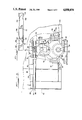
- FIG. 1 is a front view, partially broken away, of the roller assembly of the present invention installed in a door frame with the roller raised vertically with respect to the assembly housing.
- FIG. 2 is a cross-sectional side view taken along line 2--2 shown in FIG. 1.
- FIG. 3 is a front view, partially broken away, of the roller assembly shown in FIG. 1 with the roller lowered vertically with respect to the assembly housing.
- FIG. 4 is a bottom view of the slot in the door frame into which the roller assembly of the present invention is inserted.
- FIGS. 1-3 An adjustable roller assembly, generally designated by the numeral 10, is shown in FIGS. 1-3.
- the roller assembly 10 is adapted to be mounted in a recess or slot 12 provided in an upper or lower edge of a door frame 14 for sliding on a track 16 extending the width of the door frame.
- the roller assembly 10 in FIGS. 1-3 is shown installed in the lower edge of a door frame 14.
- the door frame edge defines a generally inverted U-shaped recess 18 having a flat bottom surface 18a, shown in FIG. 4, and a pair of side walls 18b, best shown in FIG. 2, depending downwardly therefrom.
- the slot 12 is defined in the flat surface 18a.
- each end of the slot 12 defines a pair of first shoulders 12a and a pair of second shoulders 12b.
- Defined between each pair of second shoulders 12b is a generally arcuate-shaped notch 19. The significance of the configuration of the slot 12 will become apparent below.
- the roller assembly 10 includes a housing 20 comprising a pair of opposing corresponding walls 22 joined together in any appropriate manner, as for example, by pins 21.
- a housing 20 comprising a pair of opposing corresponding walls 22 joined together in any appropriate manner, as for example, by pins 21.
- both side walls 22 are shown, but in FIGS. 1 and 3 the front side wall has been removed to show the inner components of the roller assembly.
- the upper end of the housing 20 is narrower than the lower end such that the edges diverge slightly from top to bottom.
- Each side wall 22 defines a generally arcuate-shaped slot 24 at the bottom thereof, the slot 24 being open at the bottom.
- the housing 20 defines a cavity 26 therein and has an opening 28 at the lower end thereof.
- each side wall 22 is provided with an outwardly laterally extending flange 30 which is disposed adjacent to and in contact with the outer lower surface 18a of the door 14 when the assembly is installed.
- Extending from each side wall 22 is a resilient locking member 32 which enables the housing 20 to be releasably locked into the recess 12.
- the locking members 32 are integral to the side walls 22 and have a free end provided with an abutment surface 34.
- a roller carrier 36 is mounted in the cavity 26 to be adjusted vertically with respect to the housing 20.
- the roller carrier 36 consists of a pair of opposing corresponding plates 38, each of which is disposed adjacent the inner side of a housing wall 22.
- a substantially U-shaped groove 40 is provided at the upper end of each plate 38, the groove 40 being open at the top.
- the lower end of each plate 38 is provided with a contoured portion 42, as best seen in FIG. 2, which defines an outwardly extending circular flange 44.
- the U-shaped grooves 40 and circular flanges 44 are vertically aligned with one another.
- Projections 46 defining cam followers, extend inwardly from plates 38 between the grooves 40 and the outwardly extending flanges 44.
- a camming element 48 is mounted within the housing 20 between the upper ends of the opposing plates 38.
- the camming element 48 defines an integral axle 50 which extends outwardly from each side of the camming element 48, as best seen in FIG. 2.
- the ends of the axle 50 are positioned within the U-shaped grooves 40 defined in the plates 38 and each end is rotatably supported in an aperture 54 defined through the upper end of each wall 22 of the housing 20, such that the axle end lies flush with the outer surface of the wall 22.
- the lower end of the camming element 48 includes a substantially arcuate slot 56, into which the cam followers 46 extend.
- the upper end of the camming element 48 defines a plurality of gear teeth 58.
- An adjustment stem 60 extends sideways from the upper end of the housing 20.
- the adjustment stem 60 is provided with a threaded portion 62 which is disposed within the housing 20 and is adapted to engage and cooperate with the gear teeth 58 on the camming element 48 to rotate the camming element 48 about its axle 50 to thereby raise or lower the roller carrier 36 with respect to the housing 20.
- a second portion 64 of the adjustment stem 60 extends laterally outwardly from the housing 20 and extends through an aperture 66 provided in the side of the door frame 14, such that the end 68 of the adjustment stem 60 lies generally flush with the outer surface of the door frame side 70.
- a slot 72 is provided in end 68 of the adjustment stem 60 to enable it to be easily rotated and adjusted from outside the door frame 14.
- a roller 74 defining an integral hub 76, is rotatably supported between the contoured portions 42 at the lower ends of the roller carrier plates 38.
- the hub 76 extends outwardly from each side of the roller 74 and is generally cylindrically-shaped so that it is supported in the circular flanges 44, as seen in FIG. 2.
- the outer periphery of the roller 74 defines a substantially U-shaped groove 78 which fits over the rail 80 provided on the track 16 on which the door frame 14 slides.
- the installation of the adjustable roller assembly is accomplished by inserting the housing 20 into the recess 12. Because of the diverging slant of the locking members 32, the upper portions of the locking members 32 contact the second shoulders 12b of the slot 12 and are biased inwardly toward the sides of the housing 20 as the roller assembly 10 is pushed upwardly through the slot 12 until the free ends of the locking members 32 pass therethrough. At that point, the locking members 32 spring outwardly trapping the flat surface 18a defined by the recess 18 between the locking members 32 and the flanges 30, such that the abutment surfaces 34 of the locking members 32 contact the upper surface 82 of surface 18a and the upper surfaces of the flanges 30 are disposed adjacent and in contact with the lower surface of the surface 18a.
- the sides of the housing 20 contact the first shoulders 12a and prevent lateral movement of the assembly 10 within the slot 12.
- the end 68 of the adjustment stem 60 is positioned to extend through the aperture 66 in the side of the door frame.
- the free ends of the locking members 32 are positioned approximately half-way across the respective notches 19. No tools are necessary for installation.
- an implement or tool is inserted through the open portions of the notches 19 and is used to press the locking members 32 inwardly to effect removal.
- the roller carrier 36 and consequently the roller 74, may be adjusted vertically with respect to the housing 20 and door frame 14 from the side edge of the door frame after installation.
- the end of a screwdriver or such is positioned in the slot 72 at the end 68 of the adjustment stem 60 and rotated one way or the other depending upon whether it is desired to raise or lower the roller carrier 36 and roller 74.
- the threaded portion 62 in engagement with the gear teeth 58 on the camming element 48 act to rotate the camming element 48 about its axis 50.
- the camming element 48 As the camming element 48 rotates, it has a camming effect on the cam followers 46 trapped in the arcuate slot 56 thereby causing the cam followers 46 to be pushed downwardly or raised upwardly depending on the direction of rotation of the adjustment stem 60. Since the cam followers 46 are integral with the plates 38, the roller carrier 36 and roller 74 are moved vertically downwardly or upwardly, respectively.
- the roller assembly 10 may be adjusted to take up the slack between the door frame 14 and the track 16 or to tighten the fit therebetween by lowering the roller 74. Conversely, the roller assembly 10 may be adjusted to increase the slack or loosen the fit therebetween by raising the roller 74.
- roller assembly which is installed in the lower edge of a door
- roller assembly may also be installed in the upper edge of a door.
- the present invention provides an easily adjustable roller assembly for sliding doors which may be installed without tools.
Landscapes
- Engineering & Computer Science (AREA)
- Mechanical Engineering (AREA)
- Support Devices For Sliding Doors (AREA)
Abstract
Description
Claims (4)
Priority Applications (1)
| Application Number | Priority Date | Filing Date | Title |
|---|---|---|---|
| US07/260,871 US4850078A (en) | 1988-10-21 | 1988-10-21 | Adjustable roller assembly for sliding doors |
Applications Claiming Priority (1)
| Application Number | Priority Date | Filing Date | Title |
|---|---|---|---|
| US07/260,871 US4850078A (en) | 1988-10-21 | 1988-10-21 | Adjustable roller assembly for sliding doors |
Publications (1)
| Publication Number | Publication Date |
|---|---|
| US4850078A true US4850078A (en) | 1989-07-25 |
Family
ID=22991000
Family Applications (1)
| Application Number | Title | Priority Date | Filing Date |
|---|---|---|---|
| US07/260,871 Expired - Lifetime US4850078A (en) | 1988-10-21 | 1988-10-21 | Adjustable roller assembly for sliding doors |
Country Status (1)
| Country | Link |
|---|---|
| US (1) | US4850078A (en) |
Cited By (15)
| Publication number | Priority date | Publication date | Assignee | Title |
|---|---|---|---|---|
| EP0801198A1 (en) * | 1996-04-10 | 1997-10-15 | FERCO INTERNATIONAL Ferrures et Serrures de Bâtiment, Société Anonyme | Rolling device for sliding doors, windows or the like |
| US5845363A (en) * | 1997-05-22 | 1998-12-08 | Quanex Corporation | Adjustable roller assembly |
| GB2346645A (en) * | 1999-02-10 | 2000-08-16 | Giltsecurity Limited | Roller assembly |
| EP0984126A3 (en) * | 1998-09-03 | 2001-02-21 | Eku Ag | Guiding device for a sliding door |
| US6321413B1 (en) * | 1999-06-10 | 2001-11-27 | Eku Ag | Running carriage for a sliding door |
| US6687954B2 (en) * | 2001-03-30 | 2004-02-10 | Eku Ag | Pulley, cradle arrangement for a sliding door |
| US20050011041A1 (en) * | 2003-06-18 | 2005-01-20 | Ness John T. | Precision machined roller wheel assembly |
| US20090145038A1 (en) * | 2004-07-24 | 2009-06-11 | Rytec Corporation | Door Assembly and Method of Making Same (Stainless Steel Sliding Door) |
| US8322076B2 (en) | 2010-07-09 | 2012-12-04 | Quanex Building Products Corporation | Adjustable glide apparatus for a sliding panel assembly |
| US20140150209A1 (en) * | 2012-12-04 | 2014-06-05 | Milgard Manufacturing Incorporated | Lift adjust sliding door roller |
| US20150026927A1 (en) * | 2013-07-26 | 2015-01-29 | Nueteq Technology, Inc. | Track beam structure |
| FR3020393A1 (en) * | 2014-04-24 | 2015-10-30 | I D Alu | WHEEL HOLDING DEVICE FOR SLIDING PANEL AND CLOSURE INSTALLATION COMPRISING SUCH A DEVICE |
| EP3075933A1 (en) * | 2015-04-03 | 2016-10-05 | Cinetto F.Lli S.R.L. | Unit for moving a sliding door of a furnishing element |
| US20180058122A1 (en) * | 2016-08-31 | 2018-03-01 | Mammoth Industries Pty Ltd | Sliding panel wheel assembly |
| WO2021087321A1 (en) * | 2019-10-30 | 2021-05-06 | Interlock Usa, Inc. | Sliding door roller and method of installation |
Citations (4)
| Publication number | Priority date | Publication date | Assignee | Title |
|---|---|---|---|---|
| US2990567A (en) * | 1959-06-29 | 1961-07-04 | Pearson Olaf | Worm operated door hanger |
| US3416183A (en) * | 1966-08-22 | 1968-12-17 | Truth Tool Company | Roller assembly for a sliding closure |
| US3698036A (en) * | 1970-10-14 | 1972-10-17 | Columbia Belford Inc | Sliding structure roller assembly |
| US4030160A (en) * | 1975-08-19 | 1977-06-21 | The Stanley Works | Corner bracket and roller assembly for sliding doors |
-
1988
- 1988-10-21 US US07/260,871 patent/US4850078A/en not_active Expired - Lifetime
Patent Citations (4)
| Publication number | Priority date | Publication date | Assignee | Title |
|---|---|---|---|---|
| US2990567A (en) * | 1959-06-29 | 1961-07-04 | Pearson Olaf | Worm operated door hanger |
| US3416183A (en) * | 1966-08-22 | 1968-12-17 | Truth Tool Company | Roller assembly for a sliding closure |
| US3698036A (en) * | 1970-10-14 | 1972-10-17 | Columbia Belford Inc | Sliding structure roller assembly |
| US4030160A (en) * | 1975-08-19 | 1977-06-21 | The Stanley Works | Corner bracket and roller assembly for sliding doors |
Cited By (24)
| Publication number | Priority date | Publication date | Assignee | Title |
|---|---|---|---|---|
| FR2747423A1 (en) * | 1996-04-10 | 1997-10-17 | Ferco Int Usine Ferrures | BEARING DEVICE FOR SLIDING DOOR, WINDOW OR THE LIKE |
| EP0801198A1 (en) * | 1996-04-10 | 1997-10-15 | FERCO INTERNATIONAL Ferrures et Serrures de Bâtiment, Société Anonyme | Rolling device for sliding doors, windows or the like |
| US5845363A (en) * | 1997-05-22 | 1998-12-08 | Quanex Corporation | Adjustable roller assembly |
| EP0984126A3 (en) * | 1998-09-03 | 2001-02-21 | Eku Ag | Guiding device for a sliding door |
| GB2346645B (en) * | 1999-02-10 | 2003-09-03 | Giltsecurity Ltd | Roller assembly |
| GB2346645A (en) * | 1999-02-10 | 2000-08-16 | Giltsecurity Limited | Roller assembly |
| US6321413B1 (en) * | 1999-06-10 | 2001-11-27 | Eku Ag | Running carriage for a sliding door |
| US6687954B2 (en) * | 2001-03-30 | 2004-02-10 | Eku Ag | Pulley, cradle arrangement for a sliding door |
| US20050011041A1 (en) * | 2003-06-18 | 2005-01-20 | Ness John T. | Precision machined roller wheel assembly |
| US8887444B2 (en) * | 2004-07-24 | 2014-11-18 | Rytec Corporation | Door assembly and method of making same (stainless steel sliding door) |
| US20090145038A1 (en) * | 2004-07-24 | 2009-06-11 | Rytec Corporation | Door Assembly and Method of Making Same (Stainless Steel Sliding Door) |
| US20090145068A1 (en) * | 2004-07-24 | 2009-06-11 | Rytec Corporation | Door Assembly and Method of Making Same (Stainless Steel Sliding Door) |
| US20090145062A1 (en) * | 2004-07-24 | 2009-06-11 | Rytec Corporation | Door Assembly and Method of Making Same (Stainless Steel Sliding Door) |
| US8322076B2 (en) | 2010-07-09 | 2012-12-04 | Quanex Building Products Corporation | Adjustable glide apparatus for a sliding panel assembly |
| US20140150209A1 (en) * | 2012-12-04 | 2014-06-05 | Milgard Manufacturing Incorporated | Lift adjust sliding door roller |
| US9085924B2 (en) * | 2012-12-04 | 2015-07-21 | Milgard Manufacturing Incorporated | Lift adjust sliding door roller |
| US20150026927A1 (en) * | 2013-07-26 | 2015-01-29 | Nueteq Technology, Inc. | Track beam structure |
| FR3020393A1 (en) * | 2014-04-24 | 2015-10-30 | I D Alu | WHEEL HOLDING DEVICE FOR SLIDING PANEL AND CLOSURE INSTALLATION COMPRISING SUCH A DEVICE |
| EP3075933A1 (en) * | 2015-04-03 | 2016-10-05 | Cinetto F.Lli S.R.L. | Unit for moving a sliding door of a furnishing element |
| US20180058122A1 (en) * | 2016-08-31 | 2018-03-01 | Mammoth Industries Pty Ltd | Sliding panel wheel assembly |
| US10711497B2 (en) * | 2016-08-31 | 2020-07-14 | Mammoth Industries Pty Ltd | Sliding panel wheel assembly |
| WO2021087321A1 (en) * | 2019-10-30 | 2021-05-06 | Interlock Usa, Inc. | Sliding door roller and method of installation |
| US11274480B2 (en) | 2019-10-30 | 2022-03-15 | Interlock Usa, Inc. | Sliding door roller and method of installation |
| US11629538B2 (en) | 2019-10-30 | 2023-04-18 | Interlock Usa, Inc. | Sliding door roller and method of installation |
Similar Documents
| Publication | Publication Date | Title |
|---|---|---|
| US4850078A (en) | Adjustable roller assembly for sliding doors | |
| US5845363A (en) | Adjustable roller assembly | |
| US5127192A (en) | Pivot shoe for removable sash | |
| CA2615240C (en) | Door roller system | |
| US6568723B2 (en) | Sash lock for a sash window | |
| US4165894A (en) | Spring loaded locking assemblies for sliding windows and the like | |
| CA1040933A (en) | Roller wheel assembly for sliding closure | |
| CA1070174A (en) | Adjustable roller assembly for sliding doors and the like | |
| US4998757A (en) | Bar enclosure for sheet metal cabinet doors | |
| US20040163209A1 (en) | Spring balance assembly | |
| US4112622A (en) | Roller assembly for sliding screen door, and the like | |
| US20010005995A1 (en) | Lockable sash assembly | |
| EP0563015B1 (en) | An adjustable trolley for sliding door and window fixtures | |
| US4805262A (en) | Sliding panel roller assembly | |
| US5008975A (en) | Hinge device | |
| EP0648908A1 (en) | Overhead mounted door holder assembly | |
| CA2147691C (en) | Sliding device for a sliding panel | |
| US2649612A (en) | Track and bracket | |
| US4253278A (en) | Roller device for a sliding closure | |
| US3011209A (en) | Hanger assembly for sliding doors | |
| US2940112A (en) | Sliding door hanger | |
| EP0684393B1 (en) | Vehicle door window regulator device and door featuring such a device | |
| US4674232A (en) | Trolley for sliding sashes in windows and door-windows | |
| JPS6133302A (en) | Double wheel caster with lock mechanism | |
| JPS6023419Y2 (en) | Shoji door roller |
Legal Events
| Date | Code | Title | Description |
|---|---|---|---|
| AS | Assignment |
Owner name: NICHOLS-HOMESHIELD, INC., A CORP. OF ILLINOIS Free format text: ASSIGNMENT OF ASSIGNORS INTEREST.;ASSIGNORS:LIBBY, SCOTT A.;PLIML, FRANK V., JR.;JOHNSON, WILLIAM M.;AND OTHERS;REEL/FRAME:004993/0208;SIGNING DATES FROM 19880815 TO 19881019 |
|
| STCF | Information on status: patent grant |
Free format text: PATENTED CASE |
|
| FEPP | Fee payment procedure |
Free format text: PAYOR NUMBER ASSIGNED (ORIGINAL EVENT CODE: ASPN); ENTITY STATUS OF PATENT OWNER: LARGE ENTITY |
|
| FPAY | Fee payment |
Year of fee payment: 4 |
|
| AS | Assignment |
Owner name: QUANEX CORPORATION Free format text: ASSIGNMENT OF ASSIGNORS INTEREST;ASSIGNOR:NICHOLS-HOMESHIELD, INC.;REEL/FRAME:007156/0082 Effective date: 19940929 |
|
| FPAY | Fee payment |
Year of fee payment: 8 |
|
| FPAY | Fee payment |
Year of fee payment: 12 |
|
| AS | Assignment |
Owner name: COMERICA BANK, AS AGENT, MICHIGAN Free format text: SECURITY INTEREST;ASSIGNOR:QUANEX CORPORATION;REEL/FRAME:013782/0001 Effective date: 20021126 |