US4838463A - Decanter with molded interlocking handle - Google Patents
Decanter with molded interlocking handle Download PDFInfo
- Publication number
- US4838463A US4838463A US07/038,642 US3864287A US4838463A US 4838463 A US4838463 A US 4838463A US 3864287 A US3864287 A US 3864287A US 4838463 A US4838463 A US 4838463A
- Authority
- US
- United States
- Prior art keywords
- neck portion
- cavity
- spout unit
- pouring spout
- receptacle
- Prior art date
- Legal status (The legal status is an assumption and is not a legal conclusion. Google has not performed a legal analysis and makes no representation as to the accuracy of the status listed.)
- Expired - Lifetime
Links
Images
Classifications
-
- A—HUMAN NECESSITIES
- A47—FURNITURE; DOMESTIC ARTICLES OR APPLIANCES; COFFEE MILLS; SPICE MILLS; SUCTION CLEANERS IN GENERAL
- A47J—KITCHEN EQUIPMENT; COFFEE MILLS; SPICE MILLS; APPARATUS FOR MAKING BEVERAGES
- A47J45/00—Devices for fastening or gripping kitchen utensils or crockery
- A47J45/06—Handles for hollow-ware articles
- A47J45/07—Handles for hollow-ware articles of detachable type
- A47J45/077—Collar handles
-
- A—HUMAN NECESSITIES
- A47—FURNITURE; DOMESTIC ARTICLES OR APPLIANCES; COFFEE MILLS; SPICE MILLS; SUCTION CLEANERS IN GENERAL
- A47G—HOUSEHOLD OR TABLE EQUIPMENT
- A47G19/00—Table service
- A47G19/12—Vessels or pots for table use
Definitions
- This invention relates to decanter vessels for containing and dispensing liquids, and more particularly to an improved decanter vessel formed of a unitary pouring spout bonded to a rigid glass or plastic receptacle. Such decanter is particularly useful for dispensing hot liquids, such as coffee.
- This invention comprises an improvement over that of my U.S. Pat. No. 4,090,648. It has been discovered that, at times, during the assembly of my decanter vessel, due to the nature of the cavity for the hot-melt material, material can inadvertently be extruded from the cavity into the bowl of the receptacle, producing an unacceptable product. Also, due to the shape of the cavity formed in the pouring spout unit, the decanter vessel is somewhat susceptible to twisting tensions which tend to loosen the pooring spout unit from the rigid receptacle. A large cavity which is spaced farther from the outlet in the pouring spout unit would tend to strengthen the pouring spout unit and also strengthen the mechanical bond between the pouring spout unit and the rigid receptacle.
- the improved decanter vessel comprises two basic components, a rigid receptacle having an integral neck portion formed thereon, and a pouring spout unit having formed therein a continuous cavity shaped to freely accommodate the neck portion without stress.
- the width of the cavity is greater than the thickness of the neck portion, forming a gap between the neck portion and the wall of the cavity.
- Flexible means joins the rigid receptacle and the pouring spout unit into the decanter vessel, forming a mechanical lock and also a fluid seal between the receptacle and the pouring spout unit.
- a trough extends coterminally with the cavity to form an overflow receptacle for the flexible means during formation of the decanter vessel.
- the trough includes means for enhancing the mechanical lock between the neck portion and the pouring spout unit.
- That enhancing means comprises one of the walls of the trough which extends at an angle into the trough. It has been found that the angle of extension of the wall is optimally approximately 7°, sufficient to increase the mechanical lock yet small enough to avoid interference with assembly of the decanter vessel.
- An edge portion is formed on the angled wall extending at a second angle away from the trough to deepen the trough yet avoid interference between the receptacle and the pouring spout unit during assembly.
- the neck portion is a generally annular protrusion extending from the receptacle, and the cavity is of annular configuration and is shaped to surround the neck portion when the decanter vessel is assembled.
- the cavity includes spaced inner and outer walls forming the cavity, with the inner wall being inclined into the the cavity.
- an annular protrusion is formed within the inner margin of the cavity to coact with the flexible means.
- the protrusion extends inwardly from the outer wall.
- the hot-melt materials available to form the flexible means joining the two components of the decanter vessel typically adhere rather poorly to either the rigid receptacle or the molded pouring spout unit.
- the pouring unit is formed of a molded plastic, the upstanding neck portion of the pouring spout unit is rather regular in its thickness and configuration, and if the flexible means does not adhere thereto, the pouring spout unit can become loosened sufficiently to rotate about the upstanding neck portion. Therefore, in accordance with one embodiment of the invention, the neck portion includes a plurality of spaced, radial notches which form an additional lock between the pouring spout unit and the rigid receptacle after the flexible means has solidified.
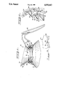
- FIG. 1 is a cross-sectional view of the upper portion of a decanter vessel according to the invention
- FIG. 2 is an enlarged fragmentary cross-sectional view of a portion of the pouring spout unit of the decanter vessel of FIG. 1, and
- FIG. 3 is an enlarged fragmentary top view of the neck portion of an embodiment of the rigid receptacle having a radial notch formed therein for enhancing the mechanical interlock between the pouring spout unit and the rigid receptacle.
- a decanter vessel 10 is composed of two basic components, a pouring spout or neckband unit 12, and a rigid receptacle 14.
- the receptacle 14 preferably formed of glass, plastic, or any other rigid, transparent material, has an integral upstanding neck portion or flange 16 formed thereon in a continuous and annular manner about the open top of dispensing aperture 18 of the receptacle 14.
- the neck portion 16 may have an enlarged integral annular bead portion 20 as illustrated, or may be formed with a generally constant thickness.
- the pouring spout unit 12 is a unitary body formed of semi-rigid material, such as polypropylene.
- a handle 22 is affixed to the pouring spout unit 12.
- the handle may be a separate element, but it is preferred that the handle 22 be formed as an integral portion of the pouring spout unit 12.
- an annular dispensing or pouring flange 24 is integrally formed in the pouring spout unit 12 with an extended pouring lip portion formed opposite the handle 22.
- the pouring spout unit 12 has formed therein an internal annular cavity 26 which, when the decanter vessel is assembled as illustrated in FIG. 1, receives and surrounds the neck portion 16 of the rigid receptacle 14.
- the cavity 26 includes an annular protrusion 28 which enhances the mechanical connection between the neck portion 16 and the pouring spout unit 12 as will be further described below.
- the annular cavity 26 of the pouring spout unit 12 is significantly wider than necessary to accommodate the neck portion 16 of the receptacle 14. This is to assure that varying diameter and varying thickness neck portions 16 can be accepted within the cavity 24.
- rigid receptacles 14 all may be formed to exactly the same specifications, due to the formulation of the material of such receptacles and conditions which exist as they are formed, a substantial variation in the size of the neck portion 16 can be expected, particularly when the receptacle is formed of glass.
- the annular cavity has spaced respective inner and outer walls 30 and 32.
- the protrusion 28 extends inwardly into the cavity 26 from the outer wall 32.
- the inner wall 30 is formed at an angle to the vertical, the angle being designated 34 in FIG. 2.
- the adjacent material 36 of the pouring spout unit 12 is thickened substantially from that if the wall 30 were vertical as set forth in my U.S. Pat. No. 4,090,648. Therefore, the adjacent portion 36 is substantially strengthened from that of my previous patent.
- a trough 38 is formed at the mouth of the cavity 26.
- the trough 38 includes a vertical outer wall 40 and an inclined inner wall 42 which extends at an angle 44 to the vertical.
- the inclination of the inner wall 42 serves several purposes, described below following the detailed description of the elements of my invention.
- a flexible bonding material 46 completely fills the void in the annular cavity 26 and surrounds the neck portion 16 to interlockingly join the rigid receptacle 16 and the pouring spout unit 12.
- the flexible material 46 is a polyamide-based material which has some degree of adherency to both the rigid receptacle 14 and the pouring spout unit 12, and yet is flexible enough to endure a wide variation of ambient temperatures.
- the flexible bonding material 46 provides a cushion to prevent the pouring spout unit 12 from breaking the neck portion 16 from the rigid receptacle 14 as the pouring spout unit 12 and the neck portion 16 expand and contract relative to one another with temperature variations.
- the flexible material 46 must allow ready assembly of the decanter vessel 10 in an expeditious and economical manner. While any flexible bonding material which can fill the cavity 26 can be employed so long as it does not impart any adverse taste or odor to the liquid dispensed from the decanter vessel 10, I have investigated a number of materials thus far and have found that only polyamide-based materials satisfy the fairly stringent requirements set forth above.
- One such material found particularly suitable is No. 6300 polyamide hot melt, manufactured by Henkel Adhesives Company.
- Another, as set forth in my U.S. Pat. No. 4,090,648, is the "Jet-Melt" hot-melt adhesive manufactured by the Minesota Mining & Manufacturing Company.
- An annular extending edge 48 extends downwardly from the inner wall 42 as best shown in FIG. 2.
- the extending edge 48 is oriented at a second angle from the trough 38 so as to avoid interference with the neck portion 16 during assembly of the decanter vessel 10, yet still form a wall for properly containing the flexible bonding material 46 within the cavity 26 and trough 38 during the forming procedure.
- Typical dimensions of the cavity 26 and trough 38 are set forth in the following table of dimensions:
- the annular bead portion 20 of a glass receptacle tends to have surface irregularities and variations in thickness which form a mechanical interlock with the bonding material 46.
- the bead portion 20 enhance mechanical lock because of its increased diameter in relation to the thickness of the neck portion 16, but also, because of the varying diameters and the surface irregularities and variations in thickness of the bead portion 20 a mechanical lock is formed to resist rotation of the pouring spout unit 12 on the neck portion 16 should any adhesive bond between the flexible bonding material 46 and the neck portion 16 be broken.
- the bead portion 20 is substantially regular in diameter and smooth, or if the rigid receptacle 14 is formed of a molded plastic material that typically has a very smooth and consistant diameter of the bead portion 20, it is ordinarily necessary to periodically notch the bead portion 20 to enhance the anti-rotational mechanical lock.
- the bead portion 20 in this instance is provided with a series of spaced, radial notches 50. During the assembly process, the flexible bonding material 46 will enter the notches 50, thus precluding the possibility of rotation of the pouring spout unit 12 on the rigid receptacle 14.
- the decanter vessel 10 is asembled in the inverted orientation from that shown in FIGS. 1 and 2.
- the internal annular cavity 26 of the pouring spout unit 12 is first filled with a liquified flexible bonding material 46.
- the neck portion 16 of the rigid receptacle 14 is inserted into the cavity 26.
- the bonding material 46 flows about the neck portion 16, being displaced as necessary to accommodate the volume of the inserted neck portion 16.
- the bonding material 46 typically extends beyond the mouth of the cavity 26 as defined by the inwardly extending protrusion 28.
- the decanter vessel 10 is maintained in the inverted orientation until the flexible bonding material 46 has solidified. At that time, the decanter vessel 10 is reinverted and is ready for use without any further manufacturing steps.
- the inwardly extending inner wall 42 tends to aid the trapping of any flexible bonding material 46 that has not solidified sufficiently when the decanter vessel 10 is reinverted during the forming process, preventing the bonding material 46 from dripping into the interior of the rigid receptacle 14.
- the neck portion 16 of the receptacle 14 is preferably provided with the enlarged bead 20.
- the internal annular cavity 26 is provided with the annular protrusion 28 so that when the flexible material 46 has solidified in the cavity 26, the enlarged bead 20 and the protrusion 28 cooperate to assure a strong mechanical lock between the rigid receptacle 14 and the pouring spout unit 12.
- the inward inclination of the inner wall 42 further enhances the mechanical lock.
- the present invention while broadly similar to that disclosed in my U.S. Pat. No. 4,090,648, includes several features which produce substantial advantages over those of my previous patent. Unlike my previous patent, I include no locking channel, but rather provide only the extended protrusion 28. I therefore can introduce more flexible bonding material 46 into the cavity 26, producing a stronger connection. The larger cavity 26 also accommodates the flexible bonding material 46 better during the forming process and provides a greater mass of bonding material, which tends to stiffen better because there is more material disposed about the upstanding neck portion 16 when the decanter vessel 10 has been assembled.
- the larger mass of the bonding material 46 creates a better mechanical bond between the pouring spout unit 12 and the rigid receptacle 14.
- the inner wall 30 is no longer vertical as that in my U.S. Pat. No. 4,090,648.
- the in-turn of the wall 30 thickens the adjacent material 36 from that in my U.S. Pat. No. 4,090,648, strengthening the pouring spout unit 12 at a critical location, reducing the flexibility of the adjacent material 36, and therefore enhancing the mechanical bond between the pouring spout unit 12 and the rigid material 14.
- the trough 38 permits more bonding material 46 to be introduced than that possible in my previous U.S. Pat. No. 4,090,648. Also, because the inner wall 42 is turned inwardly at a 7° angle to the vertical, not only does the wall 42 enhance the mechanical lock, but also the wall 42 prevents any still-flowing bonding material 46 from dripping into the interior of the decanter vessel 10 when it is reinverted during the forming process. Also, with the extension of the inner wall and its extending edge 48, any flexible bonding material 46 displaced during introduction of the rigid receptacle into the pouring spout unit will be contained and will not tend to be displaced over the edge of the cavity 26, as can occur during assembly of the decanter vessel of my previous U.S. Pat. No. 4,090,648.
Landscapes
- Engineering & Computer Science (AREA)
- Food Science & Technology (AREA)
- Details Of Rigid Or Semi-Rigid Containers (AREA)
Abstract
Description
______________________________________ Table Of Dimensions ______________________________________Angle 34 6°Angle 44 7° Depth ofcavity 36 .406" Maximum width ofcavity 26 .274" Extent ofprotrusion 28 .051" Depth oftrough 38 plusedge 48 .1875" ______________________________________
Claims (9)
Priority Applications (1)
| Application Number | Priority Date | Filing Date | Title |
|---|---|---|---|
| US07/038,642 US4838463A (en) | 1987-04-15 | 1987-04-15 | Decanter with molded interlocking handle |
Applications Claiming Priority (1)
| Application Number | Priority Date | Filing Date | Title |
|---|---|---|---|
| US07/038,642 US4838463A (en) | 1987-04-15 | 1987-04-15 | Decanter with molded interlocking handle |
Publications (1)
| Publication Number | Publication Date |
|---|---|
| US4838463A true US4838463A (en) | 1989-06-13 |
Family
ID=21901077
Family Applications (1)
| Application Number | Title | Priority Date | Filing Date |
|---|---|---|---|
| US07/038,642 Expired - Lifetime US4838463A (en) | 1987-04-15 | 1987-04-15 | Decanter with molded interlocking handle |
Country Status (1)
| Country | Link |
|---|---|
| US (1) | US4838463A (en) |
Cited By (11)
| Publication number | Priority date | Publication date | Assignee | Title |
|---|---|---|---|---|
| US4930687A (en) * | 1988-11-22 | 1990-06-05 | Melitta-Werke Bentz & Sohn | Decanter with attached spout-handle and method of making same |
| EP0426971A1 (en) * | 1989-11-10 | 1991-05-15 | Melitta Haushaltsprodukte GmbH & Co. Kommanditgesellschaft | Glass jug with a handle |
| US5110016A (en) * | 1989-08-12 | 1992-05-05 | Schott Glaswerke | Carafe and the method of making |
| US5129352A (en) * | 1990-06-15 | 1992-07-14 | Specialty Equipment Companies, Inc. | Beverage timing method and apparatus |
| US5224634A (en) * | 1991-05-20 | 1993-07-06 | Wilbur Curtis Company, Inc. | Decanter vessel and pouring spout |
| US5260914A (en) * | 1990-06-15 | 1993-11-09 | Specialty Equipment Companies, Inc. | Beverage timing method and apparatus |
| US6561390B2 (en) * | 2001-09-17 | 2003-05-13 | Sunbeam Products, Inc. | Coffee carafe with hidden handle support |
| FR2841878A1 (en) * | 2002-07-08 | 2004-01-09 | Seb Sa | Pouring handle and lid for glass container, e.g. microwaveable coffee pot, includes annular part connected to handle by a connection part having peripheral crown arranged around annular part of lid |
| US20040011799A1 (en) * | 2002-03-01 | 2004-01-22 | Roland Becker | Bonding of a plastic fixture to a glass container |
| WO2011020220A1 (en) * | 2009-08-20 | 2011-02-24 | Meyer Intellectual Properties Limited | Interlocking cookware vessel and lids |
| US8757453B1 (en) * | 2007-01-10 | 2014-06-24 | Sven O. Olsson | Pouring spout |
Citations (4)
| Publication number | Priority date | Publication date | Assignee | Title |
|---|---|---|---|---|
| US3491924A (en) * | 1968-01-08 | 1970-01-27 | Bloomfield Ind Inc | Pouring spouts for decanters |
| US3615045A (en) * | 1969-04-01 | 1971-10-26 | Corning Glass Works | Adapter top for glass decanters |
| US4090648A (en) * | 1976-04-09 | 1978-05-23 | Bloomfield Industries, A Division Of Beatrice Foods Co. | Decanter and molded interlocking handle |
| US4256333A (en) * | 1977-03-10 | 1981-03-17 | American Hospital Supply Corporation | Solvent-bonded joint |
-
1987
- 1987-04-15 US US07/038,642 patent/US4838463A/en not_active Expired - Lifetime
Patent Citations (4)
| Publication number | Priority date | Publication date | Assignee | Title |
|---|---|---|---|---|
| US3491924A (en) * | 1968-01-08 | 1970-01-27 | Bloomfield Ind Inc | Pouring spouts for decanters |
| US3615045A (en) * | 1969-04-01 | 1971-10-26 | Corning Glass Works | Adapter top for glass decanters |
| US4090648A (en) * | 1976-04-09 | 1978-05-23 | Bloomfield Industries, A Division Of Beatrice Foods Co. | Decanter and molded interlocking handle |
| US4256333A (en) * | 1977-03-10 | 1981-03-17 | American Hospital Supply Corporation | Solvent-bonded joint |
Cited By (14)
| Publication number | Priority date | Publication date | Assignee | Title |
|---|---|---|---|---|
| US4930687A (en) * | 1988-11-22 | 1990-06-05 | Melitta-Werke Bentz & Sohn | Decanter with attached spout-handle and method of making same |
| US5110016A (en) * | 1989-08-12 | 1992-05-05 | Schott Glaswerke | Carafe and the method of making |
| EP0426971A1 (en) * | 1989-11-10 | 1991-05-15 | Melitta Haushaltsprodukte GmbH & Co. Kommanditgesellschaft | Glass jug with a handle |
| US5129352A (en) * | 1990-06-15 | 1992-07-14 | Specialty Equipment Companies, Inc. | Beverage timing method and apparatus |
| US5260914A (en) * | 1990-06-15 | 1993-11-09 | Specialty Equipment Companies, Inc. | Beverage timing method and apparatus |
| US5224634A (en) * | 1991-05-20 | 1993-07-06 | Wilbur Curtis Company, Inc. | Decanter vessel and pouring spout |
| US6561390B2 (en) * | 2001-09-17 | 2003-05-13 | Sunbeam Products, Inc. | Coffee carafe with hidden handle support |
| US20040011799A1 (en) * | 2002-03-01 | 2004-01-22 | Roland Becker | Bonding of a plastic fixture to a glass container |
| US7163131B2 (en) * | 2002-03-01 | 2007-01-16 | Schott Ag | Bonding of a plastic fixture to a glass container |
| FR2841878A1 (en) * | 2002-07-08 | 2004-01-09 | Seb Sa | Pouring handle and lid for glass container, e.g. microwaveable coffee pot, includes annular part connected to handle by a connection part having peripheral crown arranged around annular part of lid |
| EP1380241A1 (en) * | 2002-07-08 | 2004-01-14 | Seb S.A. | Pouring handle for a glass container |
| CN100562274C (en) * | 2002-07-08 | 2009-11-25 | Seb公司 | The cover of toppling over kettle with glass container |
| US8757453B1 (en) * | 2007-01-10 | 2014-06-24 | Sven O. Olsson | Pouring spout |
| WO2011020220A1 (en) * | 2009-08-20 | 2011-02-24 | Meyer Intellectual Properties Limited | Interlocking cookware vessel and lids |
Similar Documents
| Publication | Publication Date | Title |
|---|---|---|
| US4838463A (en) | Decanter with molded interlocking handle | |
| US5960992A (en) | Aseptic brick package spout | |
| EP0173547A2 (en) | Container for accommodating two kinds of liquids | |
| JP4623830B2 (en) | Container assembly and bottom cap therefor | |
| US3915296A (en) | Container for mixing liquid with a material | |
| US3467269A (en) | Compartmented glass bottles | |
| US5101993A (en) | Closure seal | |
| US5664705A (en) | Sealed container for liquids particularly beverages | |
| US6439429B1 (en) | Tamper-evident closure and spout fitment for a pouch | |
| SI9600251A (en) | Shaker and blender | |
| US20100315897A1 (en) | Disposable shaker | |
| JPH0219258A (en) | Improved dispensing cover | |
| US4090648A (en) | Decanter and molded interlocking handle | |
| AU7519094A (en) | Aseptic brick package | |
| MXPA02004403A (en) | Improved pourer and incorporated pourer cap. | |
| US20150305527A1 (en) | Cup | |
| WO2008144707A2 (en) | Container lid with cutting mechanism for allowing easy-open access to products in sealed containers and beverage container including container lid | |
| JP5070195B2 (en) | Packaging containers, especially cans | |
| US4934585A (en) | Packaging container for foodstuffs | |
| JPH0813291B2 (en) | Pot and how to make it | |
| US6692780B1 (en) | Beverage infusion device | |
| US4624384A (en) | Lid for drinking containers | |
| JP2002520232A (en) | Outlet assembly for liquid filled container | |
| CZ292073B6 (en) | Container | |
| EP0024801A1 (en) | One-piece dispensing closure |
Legal Events
| Date | Code | Title | Description |
|---|---|---|---|
| AS | Assignment |
Owner name: BLOOMFIELD INDUSTRIES, INC., 4546 WEST 47TH STREET Free format text: ASSIGNMENT OF ASSIGNORS INTEREST.;ASSIGNOR:ROBERTS, MELVIN F.;REEL/FRAME:004693/0075 Effective date: 19870330 |
|
| STCF | Information on status: patent grant |
Free format text: PATENTED CASE |
|
| CC | Certificate of correction | ||
| FEPP | Fee payment procedure |
Free format text: PAYOR NUMBER ASSIGNED (ORIGINAL EVENT CODE: ASPN); ENTITY STATUS OF PATENT OWNER: LARGE ENTITY |
|
| FPAY | Fee payment |
Year of fee payment: 4 |
|
| AS | Assignment |
Owner name: BARCLAYS BUSINESS CREDIT, INC., AS AGENT, ILLINOIS Free format text: PATENT, TRADEMARK AND LICENSE MORTGAGE;ASSIGNOR:SPECIALTY EQUIPMENT COMPANIES, INC.;REEL/FRAME:006796/0132 Effective date: 19931201 Owner name: BARCLAYS BUSINESS CREDIT, INC., AS AGENT, ILLINOIS Free format text: PATENT, TRADEMARK AND LICENSE MORTGAGE;ASSIGNOR:SPECIALTY EQUIPMENT COMPANIES, INC.;REEL/FRAME:006934/0001 Effective date: 19931201 |
|
| AS | Assignment |
Owner name: SHAWMUT CAPITAL CORPORATION, WISCONSIN Free format text: ASSIGNMENT OF ASSIGNORS INTEREST;ASSIGNOR:BARCLAYS BUSINESS CREDIT, INC.;REEL/FRAME:007526/0559 Effective date: 19950131 |
|
| FPAY | Fee payment |
Year of fee payment: 8 |
|
| AS | Assignment |
Owner name: SPECIALTY EQUIPMENT COMPANIES, INC., ILLINOIS Free format text: RELEASE OF PATENT, TRADEMARK AND LICENSE MORTGAGE;ASSIGNOR:FLEET CAPITAL CORPORATION F/K/A SHAWMUT CAPITAL CORPORATION;REEL/FRAME:008321/0102 Effective date: 19961204 |
|
| FEPP | Fee payment procedure |
Free format text: PAYER NUMBER DE-ASSIGNED (ORIGINAL EVENT CODE: RMPN); ENTITY STATUS OF PATENT OWNER: LARGE ENTITY |
|
| FPAY | Fee payment |
Year of fee payment: 12 |