US4759465A - Tear strip closure for a container with a security ring - Google Patents
Tear strip closure for a container with a security ring Download PDFInfo
- Publication number
- US4759465A US4759465A US07/092,480 US9248087A US4759465A US 4759465 A US4759465 A US 4759465A US 9248087 A US9248087 A US 9248087A US 4759465 A US4759465 A US 4759465A
- Authority
- US
- United States
- Prior art keywords
- skirt
- tab
- closure
- tear strip
- lift tab
- Prior art date
- Legal status (The legal status is an assumption and is not a legal conclusion. Google has not performed a legal analysis and makes no representation as to the accuracy of the status listed.)
- Expired - Lifetime
Links
Images


Classifications
-
- B—PERFORMING OPERATIONS; TRANSPORTING
- B65—CONVEYING; PACKING; STORING; HANDLING THIN OR FILAMENTARY MATERIAL
- B65D—CONTAINERS FOR STORAGE OR TRANSPORT OF ARTICLES OR MATERIALS, e.g. BAGS, BARRELS, BOTTLES, BOXES, CANS, CARTONS, CRATES, DRUMS, JARS, TANKS, HOPPERS, FORWARDING CONTAINERS; ACCESSORIES, CLOSURES, OR FITTINGS THEREFOR; PACKAGING ELEMENTS; PACKAGES
- B65D43/00—Lids or covers for rigid or semi-rigid containers
- B65D43/02—Removable lids or covers
- B65D43/0235—Removable lids or covers with integral tamper element
- B65D43/0237—Removable lids or covers with integral tamper element secured by snapping over beads or projections before removal of the tamper element
- B65D43/0239—Removable lids or covers with integral tamper element secured by snapping over beads or projections before removal of the tamper element inside a peripheral U-shaped channel in the mouth of the container
- B65D43/0243—Removable lids or covers with integral tamper element secured by snapping over beads or projections before removal of the tamper element inside a peripheral U-shaped channel in the mouth of the container leaving friction on both the inside and the outside after removal of the tamper element
-
- B—PERFORMING OPERATIONS; TRANSPORTING
- B65—CONVEYING; PACKING; STORING; HANDLING THIN OR FILAMENTARY MATERIAL
- B65D—CONTAINERS FOR STORAGE OR TRANSPORT OF ARTICLES OR MATERIALS, e.g. BAGS, BARRELS, BOTTLES, BOXES, CANS, CARTONS, CRATES, DRUMS, JARS, TANKS, HOPPERS, FORWARDING CONTAINERS; ACCESSORIES, CLOSURES, OR FITTINGS THEREFOR; PACKAGING ELEMENTS; PACKAGES
- B65D43/00—Lids or covers for rigid or semi-rigid containers
- B65D43/02—Removable lids or covers
- B65D43/0235—Removable lids or covers with integral tamper element
- B65D43/0237—Removable lids or covers with integral tamper element secured by snapping over beads or projections before removal of the tamper element
- B65D43/0256—Removable lids or covers with integral tamper element secured by snapping over beads or projections before removal of the tamper element only on the outside, or a part turned to the outside, of the mouth of the container
- B65D43/0258—Removable lids or covers with integral tamper element secured by snapping over beads or projections before removal of the tamper element only on the outside, or a part turned to the outside, of the mouth of the container leaving friction on both the inside and the outside after removal of the tamper element
-
- B—PERFORMING OPERATIONS; TRANSPORTING
- B65—CONVEYING; PACKING; STORING; HANDLING THIN OR FILAMENTARY MATERIAL
- B65D—CONTAINERS FOR STORAGE OR TRANSPORT OF ARTICLES OR MATERIALS, e.g. BAGS, BARRELS, BOTTLES, BOXES, CANS, CARTONS, CRATES, DRUMS, JARS, TANKS, HOPPERS, FORWARDING CONTAINERS; ACCESSORIES, CLOSURES, OR FITTINGS THEREFOR; PACKAGING ELEMENTS; PACKAGES
- B65D2401/00—Tamper-indicating means
- B65D2401/15—Tearable part of the closure
- B65D2401/25—Non-metallic tear-off strips
-
- B—PERFORMING OPERATIONS; TRANSPORTING
- B65—CONVEYING; PACKING; STORING; HANDLING THIN OR FILAMENTARY MATERIAL
- B65D—CONTAINERS FOR STORAGE OR TRANSPORT OF ARTICLES OR MATERIALS, e.g. BAGS, BARRELS, BOTTLES, BOXES, CANS, CARTONS, CRATES, DRUMS, JARS, TANKS, HOPPERS, FORWARDING CONTAINERS; ACCESSORIES, CLOSURES, OR FITTINGS THEREFOR; PACKAGING ELEMENTS; PACKAGES
- B65D2543/00—Lids or covers essentially for box-like containers
- B65D2543/00009—Details of lids or covers for rigid or semi-rigid containers
- B65D2543/00018—Overall construction of the lid
- B65D2543/00027—Stackable lids or covers
-
- B—PERFORMING OPERATIONS; TRANSPORTING
- B65—CONVEYING; PACKING; STORING; HANDLING THIN OR FILAMENTARY MATERIAL
- B65D—CONTAINERS FOR STORAGE OR TRANSPORT OF ARTICLES OR MATERIALS, e.g. BAGS, BARRELS, BOTTLES, BOXES, CANS, CARTONS, CRATES, DRUMS, JARS, TANKS, HOPPERS, FORWARDING CONTAINERS; ACCESSORIES, CLOSURES, OR FITTINGS THEREFOR; PACKAGING ELEMENTS; PACKAGES
- B65D2543/00—Lids or covers essentially for box-like containers
- B65D2543/00009—Details of lids or covers for rigid or semi-rigid containers
- B65D2543/00018—Overall construction of the lid
- B65D2543/00064—Shape of the outer periphery
- B65D2543/00074—Shape of the outer periphery curved
- B65D2543/00092—Shape of the outer periphery curved circular
-
- B—PERFORMING OPERATIONS; TRANSPORTING
- B65—CONVEYING; PACKING; STORING; HANDLING THIN OR FILAMENTARY MATERIAL
- B65D—CONTAINERS FOR STORAGE OR TRANSPORT OF ARTICLES OR MATERIALS, e.g. BAGS, BARRELS, BOTTLES, BOXES, CANS, CARTONS, CRATES, DRUMS, JARS, TANKS, HOPPERS, FORWARDING CONTAINERS; ACCESSORIES, CLOSURES, OR FITTINGS THEREFOR; PACKAGING ELEMENTS; PACKAGES
- B65D2543/00—Lids or covers essentially for box-like containers
- B65D2543/00009—Details of lids or covers for rigid or semi-rigid containers
- B65D2543/00018—Overall construction of the lid
- B65D2543/00259—Materials used
- B65D2543/00296—Plastic
-
- B—PERFORMING OPERATIONS; TRANSPORTING
- B65—CONVEYING; PACKING; STORING; HANDLING THIN OR FILAMENTARY MATERIAL
- B65D—CONTAINERS FOR STORAGE OR TRANSPORT OF ARTICLES OR MATERIALS, e.g. BAGS, BARRELS, BOTTLES, BOXES, CANS, CARTONS, CRATES, DRUMS, JARS, TANKS, HOPPERS, FORWARDING CONTAINERS; ACCESSORIES, CLOSURES, OR FITTINGS THEREFOR; PACKAGING ELEMENTS; PACKAGES
- B65D2543/00—Lids or covers essentially for box-like containers
- B65D2543/00009—Details of lids or covers for rigid or semi-rigid containers
- B65D2543/00444—Contact between the container and the lid
- B65D2543/00481—Contact between the container and the lid on the inside or the outside of the container
- B65D2543/0049—Contact between the container and the lid on the inside or the outside of the container on the inside, or a part turned to the inside of the mouth of the container
- B65D2543/00509—Cup
-
- B—PERFORMING OPERATIONS; TRANSPORTING
- B65—CONVEYING; PACKING; STORING; HANDLING THIN OR FILAMENTARY MATERIAL
- B65D—CONTAINERS FOR STORAGE OR TRANSPORT OF ARTICLES OR MATERIALS, e.g. BAGS, BARRELS, BOTTLES, BOXES, CANS, CARTONS, CRATES, DRUMS, JARS, TANKS, HOPPERS, FORWARDING CONTAINERS; ACCESSORIES, CLOSURES, OR FITTINGS THEREFOR; PACKAGING ELEMENTS; PACKAGES
- B65D2543/00—Lids or covers essentially for box-like containers
- B65D2543/00009—Details of lids or covers for rigid or semi-rigid containers
- B65D2543/00444—Contact between the container and the lid
- B65D2543/00481—Contact between the container and the lid on the inside or the outside of the container
- B65D2543/00537—Contact between the container and the lid on the inside or the outside of the container on the outside, or a part turned to the outside of the mouth of the container
-
- B—PERFORMING OPERATIONS; TRANSPORTING
- B65—CONVEYING; PACKING; STORING; HANDLING THIN OR FILAMENTARY MATERIAL
- B65D—CONTAINERS FOR STORAGE OR TRANSPORT OF ARTICLES OR MATERIALS, e.g. BAGS, BARRELS, BOTTLES, BOXES, CANS, CARTONS, CRATES, DRUMS, JARS, TANKS, HOPPERS, FORWARDING CONTAINERS; ACCESSORIES, CLOSURES, OR FITTINGS THEREFOR; PACKAGING ELEMENTS; PACKAGES
- B65D2543/00—Lids or covers essentially for box-like containers
- B65D2543/00009—Details of lids or covers for rigid or semi-rigid containers
- B65D2543/00444—Contact between the container and the lid
- B65D2543/00481—Contact between the container and the lid on the inside or the outside of the container
- B65D2543/00555—Contact between the container and the lid on the inside or the outside of the container on both the inside and the outside
-
- B—PERFORMING OPERATIONS; TRANSPORTING
- B65—CONVEYING; PACKING; STORING; HANDLING THIN OR FILAMENTARY MATERIAL
- B65D—CONTAINERS FOR STORAGE OR TRANSPORT OF ARTICLES OR MATERIALS, e.g. BAGS, BARRELS, BOTTLES, BOXES, CANS, CARTONS, CRATES, DRUMS, JARS, TANKS, HOPPERS, FORWARDING CONTAINERS; ACCESSORIES, CLOSURES, OR FITTINGS THEREFOR; PACKAGING ELEMENTS; PACKAGES
- B65D2543/00—Lids or covers essentially for box-like containers
- B65D2543/00009—Details of lids or covers for rigid or semi-rigid containers
- B65D2543/00444—Contact between the container and the lid
- B65D2543/00592—Snapping means
- B65D2543/00601—Snapping means on the container
- B65D2543/00611—Profiles
- B65D2543/00629—Massive bead
-
- B—PERFORMING OPERATIONS; TRANSPORTING
- B65—CONVEYING; PACKING; STORING; HANDLING THIN OR FILAMENTARY MATERIAL
- B65D—CONTAINERS FOR STORAGE OR TRANSPORT OF ARTICLES OR MATERIALS, e.g. BAGS, BARRELS, BOTTLES, BOXES, CANS, CARTONS, CRATES, DRUMS, JARS, TANKS, HOPPERS, FORWARDING CONTAINERS; ACCESSORIES, CLOSURES, OR FITTINGS THEREFOR; PACKAGING ELEMENTS; PACKAGES
- B65D2543/00—Lids or covers essentially for box-like containers
- B65D2543/00009—Details of lids or covers for rigid or semi-rigid containers
- B65D2543/00444—Contact between the container and the lid
- B65D2543/00592—Snapping means
- B65D2543/00601—Snapping means on the container
- B65D2543/00675—Periphery concerned
- B65D2543/00685—Totality
-
- B—PERFORMING OPERATIONS; TRANSPORTING
- B65—CONVEYING; PACKING; STORING; HANDLING THIN OR FILAMENTARY MATERIAL
- B65D—CONTAINERS FOR STORAGE OR TRANSPORT OF ARTICLES OR MATERIALS, e.g. BAGS, BARRELS, BOTTLES, BOXES, CANS, CARTONS, CRATES, DRUMS, JARS, TANKS, HOPPERS, FORWARDING CONTAINERS; ACCESSORIES, CLOSURES, OR FITTINGS THEREFOR; PACKAGING ELEMENTS; PACKAGES
- B65D2543/00—Lids or covers essentially for box-like containers
- B65D2543/00009—Details of lids or covers for rigid or semi-rigid containers
- B65D2543/00444—Contact between the container and the lid
- B65D2543/00592—Snapping means
- B65D2543/00712—Snapping means on the lid
- B65D2543/00722—Profiles
- B65D2543/0074—Massive bead
-
- B—PERFORMING OPERATIONS; TRANSPORTING
- B65—CONVEYING; PACKING; STORING; HANDLING THIN OR FILAMENTARY MATERIAL
- B65D—CONTAINERS FOR STORAGE OR TRANSPORT OF ARTICLES OR MATERIALS, e.g. BAGS, BARRELS, BOTTLES, BOXES, CANS, CARTONS, CRATES, DRUMS, JARS, TANKS, HOPPERS, FORWARDING CONTAINERS; ACCESSORIES, CLOSURES, OR FITTINGS THEREFOR; PACKAGING ELEMENTS; PACKAGES
- B65D2543/00—Lids or covers essentially for box-like containers
- B65D2543/00009—Details of lids or covers for rigid or semi-rigid containers
- B65D2543/00444—Contact between the container and the lid
- B65D2543/00592—Snapping means
- B65D2543/00712—Snapping means on the lid
- B65D2543/00787—Periphery concerned
- B65D2543/00796—Totality
Definitions
- This invention relates to a plastic closure which is made inexpensively with injection molding equipment, and more particularly, to such a closure which has a tamper-evident band or tear-off strip which is removed the first time the closure is open to provide a tamper-evident feature for the container and closure and which has a lift-off tab for ease in removing the closure after removal of the tear-off strip.
- the present invention is particularly useful with a container which has a security or saturn ring or ledge on the container side wall projecting outwardly of the container side wall at a location immediately below the skirt of the closure to limit access to the lower edge of a tear strip.
- the container security ring projects radially outwardly from the wall of the container and has a larger outer diameter than that of the closure skirt, it is relatively difficult to obtain direct access to the tear-off strip and to remove the closure unless a lift tab remains after removal of the tear-off strip.
- the security ring protects the strip against accidentally being caught or torn during handling and shipping of the assembled closure and container.
- the now lower edge of the remaining skirt is at the location spaced above but still close to the security ring. If one inserts a fingernail under the lower edge of the remaining skirt, the nail hits the container bead and makes removal of the closure difficult. Thus, when a security ring is located slightly below this lower edge of the skirt, it is almost impossible to insert a fingernail under the lower edge of the skirt and to remove the closure with a simple lifting motion.
- the present invention provides a lifting tab which is accessible after removal of the tear-off strip and which is plainly visible and apparent to the customer that the tab is to be used to lift off the closure.
- the lift-off tab is formed by grasping an end of a pull tab and breaking a first bridge or connection between the pull tab and the skirt and pulling the pull tab to cause a second bridge to become effective to pull a first end of the lift tab outwardly from the skirt wall.
- the skirt wall tears at the thin cross section of the groove and pivots outwardly to form an outer lift tab portion, and the skirt wall stops tearing at a thicker portion of the tab on the lower part of the skirt. A continued pull of the pulling tab removes all of the tear-off strip.
- the present invention uses a fracturable bridge between the pull strip and the lift tab to pull the lift tab radially outwardly so that it is very visible and accessible particularly where the closure has a security ring.
- the fracturable bridge pivots the lift tab outwardly about a vertical hinge axis with the skirt wall prior to the bridge fracturing.
- closure and container of the present invention are inexpensively molded in one piece at high speeds and at a relatively low cost.
- the container may be a one-piece molded container of plastic made at high speeds and at low cost.
- the invention is directed to a commercially feasible closure and container which can be used for a wide variety of products can be manufactured easily and at high rates to provide an inexpensive closure and/or container.
- a general object of the present invention is to provide a new and improved closure with a new and improved pull tab and lift tab which separate from each other consistently when the pull tab is pulled to form the lift tab.
- FIG. 1 is a perspective view of a container and closure constructed in accordance with one embodiment of the invention.
- FIG. 2 is an enlarged fragmentary side elevational view of the closure and the top marginal portion of the container.
- FIG. 3 is a plan view of the closure shown in FIG. 2.
- FIG. 4 is a fragmentary view showing the stacking of closures of the invention.
- FIG. 4A is an enlarged cross sectional fragmentary view of closure interlocked to a container rim.
- FIG. 5 is a perspective view of the closure having a tear strip and a pull tab constructed in accordance with one embodiment of the invention.
- FIG. 6 is a perspective view similar to FIG. 5 but with the pull tab and tear strip partially removed.
- FIG. 7 is a view similar to FIG. 6 but of another embodiment of the invention.
- FIG. 8 is an enlarged fragmentary view of the pull tab prior to its detachment.
- FIG. 9 is a view similar to FIG. 8 with the pull tab detached.
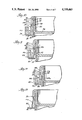
- FIG. 10 is an enlarged cross-sectional view taken substantially along the line 10--10 of FIG. 8.
- FIG. 11 is an enlarged cross-sectional view taken along the line 11--11 of FIG. 8.
- FIG. 12 is cross sectional view taken substantially along the line of 12--12 of FIG. 8.
- FIG. 13 is an enlarged cross-sectional view taken substantially along the line 13--13 of FIG. 8.
- FIG. 14 illustrates a closure constructed in accordance with a still further embodiment of the invention.
- FIG. 15 illustrates a preferred embodiment of the invention.
- FIG. 16 illustrates an enlarged elevational view of the pull tab and lift-off tab of FIG. 15.
- FIG. 17 is a perspective view of a portion of the tear strip, the pull tab and lift-off tab of FIG. 15 prior to closure removal.
- FIG. 18 is a view similar to FIG. 17 with the pull tab partially separated by the lift-off tab.
- FIG. 19 is a cross sectional view taken along the line 19--19 of FIG. 17.
- FIG. 20 is a cross sectional view taken along the line 20--20 of FIG. 17.
- the invention is embodied in a container 10 having a closure 11 which is press-fitted and snap-fitted on the container, and in sealing engagement to cover the open mouth of the container.
- the illustrated and preferred container 10 is formed with an integral security ring 12, sometimes called a "Saturn" ring which is an integral projecting ring or flange which projects radially outwardly from a cylindrical wall 14 (FIG. 10) of the container.
- the security ring extends generally horizontally from its inner edge which is connected to an inner container wall 14 to an outer peripheral circular edge 15.
- the closure 11 has a skirt wall 18 which projects downwardly and encircles the rim 20 of the container, as best seen in FIGS. 4A and 10.
- the rim 20 of the container wall 14 projects upwardly into a generally inverted "U" shaped portion of the closure defined between the skirt 18 and an inverted depending inner leg or wall 22 of the closure.
- the leg 22 extends downwardly and is integral with a top circular panel 24.
- the skirt 18 and the inner leg 22 are spaced from each other as shown by the space or gap 26 in FIGS. 9-12.
- the space 26 is narrower than the distance between the skirt 18 and inner leg 22 such that the closure is frictionally retained on the container when the rim is forced between the skirt and the inner leg.
- interlocking means 28 comprises an integral outwardly projecting bead 32 on the container which has an upper, inclined surface 33, which slopes downwardly, for example, at 45° which will cam against the skirt wall as will be described in greater detail hereinafter until a recess or groove 36 (FIG. 12) on the skirt 18 is aligned and has received the bead 32, therein.
- the container rim and bead 32 have been broken away in FIG. 12 to provide a better view of the groove 36.
- a lower shoulder 38 on the skirt at the recess 36 abuts a lower generally horizontally extending, lower shoulder 39 on the bead 32 to prevent upward lifting movement of the closure from the container.
- a lower edge 40 of the skirt 18 is disposed immediately above and may be in engagement with a top surface 42 of the security ring 12 when the closure is interlocked with the bead on the container.
- the security ring 12 will most likely be used in instances where, e.g., where the closure is very flexible, and there is concern that someone could remove the closure by pushing up on the lower edge 40 of the tamper-evident band and push the closure upwardly from the container without tearing off the tamper-evident band 50.
- the person buying the containers may not desire a security ring 12 and rely on the snap-fit engagement of closure to container to hold the closure against someone trying to push against the lower edge 40 of the tamper-evident band 50 and to push the closure off without first removing the tamper-evident band.
- the present invention is directed to containers with or without the security ring 12 and to alleviating the problem of removal of the closure, after the tamper-evident band has been removed leaving a lower edge 40a of the skirt 18 (FIGS. 6 and 7) located adjacent the container bead 50 such that a fingernail inserted below this skirt edge 40a hits the container bead 32 thereby making it difficult to lift the closure from the container without the use of a lift tab.
- the tear-off or tamper indicating band or strip 50 along a lower portion 51 of the skirt 18 which detaches along the line of weakness 52, which is a thin web 89, from the upper portion 53 of the skirt 18.
- the line of weakness 52 may be at any place brt herein it is located at the thinnest cross section in the skirt and formed at a wall 54 (FIG. 12), which is at the outer, bottom portion of the recess 36.
- the preferred tear strip 50 has a pull-off tab 60 which the user will grasp and pull on to remove the tear strip 50.
- a new and improved one-piece closure having a pull tab 60 to tear off the tear strip 50 and which exposes and makes accessible a lift tab 67 for grasping by the user to lift the closure upwardly from the container.
- the lift-off tab 67 is initially hidden behind the pull tab 60 and is pulled outwardly to be exposed and accessible after the pull tab is grasped and pulled by the user.
- the user will insert a fingernail, or tool, into a slot 63, as best seen in FIG. 8 and will pry outwardly on an enlarged knob or free end 64 of the pull tab to break a frangible bridge 65 (FIG.
- a second frangible bridge 66 which is located more closely adjacent a hinge portion 68 which hinges the pull tab to the tear strip.
- the bridge 66 breaks and tears from the pull tab leaving a large lift portion or lift tab 67 for lifting the closure from the container.
- the pull tab swings radially outwardly as shown in FIGS. 6, 7 and 9, it pulls the lift tab radially outwardly and also upwardly so that the lift tab remains spaced above the security ring 12 and projecting outwardly of the skirt for easy noticeability and ease of grasping by the person desiring to lift-off the closure and to have access to the contents of the container.
- the pull tab 60 generally covers and hides the lift tab as seen in FIG. 5, and as the pull tab is pulled outwardly it breaks the bridge 65, as seen in FIG. 6 and also breaks the bridge 66; and, during the pulling of the bridge 66 to its breaking point, the bridge pulls the lift tab upwardly and outwardly to insure its exposure or visibility.
- the lift tab 67 is integrally connected at a hinge line or portion to the bottom of the skirt wall 40a this hinge line at the web 89 at the bead recess 36 in the skirt.
- the lift tab 67 shown in FIGS. 6, 7 and 12 includes a tip or portion 66b which was part of the bridge 66 and longer body 67a which was disposed downwardly in alignment with tamper-evident band 50.
- the first frangible bridge 65 is preferably located on the lower edge of the removable tear strip 50 and extends radially outwardly therefrom to an inner vertical wall 70 on the pull tab 60, as best seen in FIG. 8.
- the frangible bridge 65 usually tears with a small portion 65aremaining on the pull tab 60 (FIG. 9) and a small portion 65b of the bridge 65 remains on the tear strip 50.
- the bridges 65 and 66 span a slot 72 (FIG. 8) located between the inner vertical wall 70 of the tear strip and a facing vertical wall 73 of the pull tab.
- the slot 72 is a thin narrow space extending arcuately, as best seen in FIG. 7, between the bridges 65 and 66.
- the pull tab is spaced outwardly of the tear strip 50 by the bridges 65 and 66 and the hinge portion 68.
- the illustrated pull tab 60 is preferably provided with some outer vertical ribs or corrugations 80 along its outer surface.
- the ribs 80 provide a better gripping surface to prevent sliding of the fingers off of the tab.
- the preferred hinge is generally bowed with a generally arcuately shape section 84 adjacent the second bridge 66 which spaces the attached end of the tab radially outwardly from the lower portion of the skirt 18 and causes formation of the slot 72.
- the preferred second bridge 66 preferably breaks into small portion 66a which remains attached to the pull tab 60, as best seen in FIG. 8, and with a much larger portion 66b which forms an end of the lift tab 67 and is attached to the body 67a of the lift tab 67.
- the lift tab 67 of FIGS. 8 and 9 is integrally attached to the tear strip 50 and in alignment therewith and is formed when the tear strip band is separated therefrom at V-shaped notches 86 when the tear strip is removed. More specifically, as shown in FIG. 9, the initial separation of the pull tab 60 and the initial tearing of tear strip along the line of weakness 52 also results in the fracturing a small web 86a (FIG. 8) at the bottom of the notch 86. The web 86a had joined the right side of the lift tab body 67a to adjacent portion of the tear strip 50. The removal of the tear strip is completed when the tear strip is pulled along the line of weakness 52 to the left hand notch 86 at which is a small fracturable web 86b of plastic joining the tear strip to the left side of the lift tab 67.
- the outer side of the lift tab has been formed to come straight downwardly along a surface 88 resulting a thicker web 89 of plastic between the bottom wall 54 of the recess and the outer surface 88.
- the web 89 between the bottom wall 54 and outer surface 90 is much thinner as shown in FIG. 11 which shows a cross section located not at the lift tab.
- the surface 90 extends substantially more vertically than inclined surface 88.
- This increased thickness at the web 89 for the lift tab also provides a thicker hinge web 89 so that the lift tab will not break when a strong lift force is being applied thereto.
- the web 89 in FIG. 11 may be about 0.005 inch thick and the web 89 in FIG. 12 may be about twice as thick.
- the illustrated closures may be readily stacked, as shown in FIG. 4, for automatic feeding and delivering to a capping device which merely pushes the closure down onto the container rim to snap the recess over the container bead to interlock the closure to the container.
- a lower and inner edge or corner 100 of the skirt 18 abuts and rests on an upper, rounded corner 101 of the closure next below in the stack.
- a lower corner 105 formed between the inner leg 22 and the central panel 24 rests on the upper circular corner 107 which joins the skirt leg to the inner annular leg 22.
- a pull tab 160 is detached by pulling the end 164 to break a first bridge 165 for connecting the pull tab to the lower end of the skirt.
- the pull tab 160 is pulled to remove the tamper-evident band 150 and to form the lift tab 167.
- a frangible second bridge 166 extends between the lift tab 167 and the pull tab 160.
- the lift tab is hinged along a vertical hinge line 115 to a portion 116 located inwardly of the pull tab.
- Notches similar to the notches 86 previously described are formed to provide frangible, thin webs which break to form trailing edge 118 of the tear-off strip 150 and to form an adjacent vertical side edge 119 for the lift tab.
- the web 89 located at the bottom wall of the recess may be made thinner at the location of the lift tab so as fracture and leave a top end wall 121 on the lift tab. Because the bridge 166 is stronger than the webs at locations of the tab edges 119 and 121, a pull on the pull tab 160 breaks these webs and forms the lift tab.
- the portion 116 may be thickened in cross section so that the web 89 is thicker at the portion 116 and therefor will not tear.
- a continued pull on the pull tab forms the lift tab and then fractures second bridge 166 before tearing away at the line of weakness 152 at the thin web at the bottom of the groove in the skirt wall to allow removal of the tear strip.
- the lift tab is hingedly connected at hinge line 115, which defines a vertical hinge axis, to the portion 116 and projects outwardly therefrom to be noticed by user who will know to grasp and lift the closure by the lift-off tab.
- the lift tab is formed at the end of the tear strip during its removal from the closure. More specifically, the tear strip (which is shown in phantom) has a pull tab 260 connected by a bridge 265 which tears and leaves a piece 265a. Continued tearing the tear strip 250 from the closure forms the lift tab 267. A notched web 201 formed between and end 202 for the tear strip and an adjacent vertical outer end 203 of the lift tab. The web 201 is thicker and stronger than the web 89 at the bottom of the bead groove at the area of the lift tab so that the web 89 first fractures to form top edge 205 for the lift tab.
- the preferred and illustrated closure comprises a top panel 324 and the encircling outer skirt 318 which integrally attached thereto.
- a locking means 328 such as the groove and the bead on the container lock the closure to the container.
- the illustrated pull-tab 360 has a first bridge 365 (FIG. 17) which is connected at one end to the skirt 318.
- the first bridge fractures upon pulling the pull tab 360 radially outwardly, and then a second frangible means in the form of a second frangible bridge 366 pulls the lift tab 367 radially outwardly into view and to be accessible for grasping.
- the upper portion of the lift tab has an upper top end wall 321 which separates from the skirt wall.
- the thickened portion 316 appears as a thickened block having an outer vertical surface 316a defined between vertical edges 316b and 316c.
- the thickened portion extends vertically from the lower tear-off strip 350 area into the upper portion of the skirt 318. That is, the increased thickness and widths still did not overcome the problem of an occasional failure of separation between the pull tab and the lift tab thereby leaving no pull tab on the closure to aid in the closure removal from the container.
- the additional cross sectional material 379 has been added into the groove 336 so that the web 389 (FIG. 20) is substantially thicker, for example, an additional 0.010 inch thicker than the web 389 (FIG. 19) for the remainder of the groove 336.
- the circumferential extent of the thickened portion 379 is very limited, for example, about 1/16th of an inch so that it is barely noticeable to the eye and does not form a very long discontinuity in the groove 336.
- the additional plastic material 379 in the groove 336 begins at the vertical side 316b of the thickened porton and extends for 1/16th of an inch to the right as viewed in FIGS. 17 and 18.
- the person desiring to remove the closure will grasp the knob or free end 364 and pull on the pull tab 360 to fracture the first frangible bridge 365 leaving a small portion 365a attached to the ring and another small portion 365b attached to the outer knob or free-end 364.
- the first or removed portion of the pull tab is spaced by the space 372 from the skirt 318 and is joined to the skirt at the second bridge 366 which is about mid-way in the length of the pull tab.
- the bridge 366 extends from the inner vertical sidewall of the pull tab to the outer facing side of the lift tab 367 at what will be the outer free end of the lift tab.
- the continued pull of the pull tab 360 causes an immediate tearing on the lift tab 367 with the separation being at the first reduced notch thickness area 386 as best seen in FIG. 17 to form a vertical free end wall 367a (FIG. 15).
- the tearing of the lift-off tab is at the line of weakness 352 with the thin cross sectional web 389 being torn easily and forming the top wall 321 on the lift tab as best seen in FIG. 15. Because the lift tab is being swung outwardly by the pull tab, it assumes a position where it can be easily seen and understood to be a lift tab for removal of the closure from the container.
- a continued severing along the line of weakness 352 at the thin web 389 continues until the tear reaches the thickened cross material 379 (FIG.
- the thickened web 389 is at the vertical hinge line located at the vertical wall 316b between the lift tab and the thickened portion 319 thereby providing a good strong connection for the lift tab so that the same may be used repetitively without breaking off for a number of removals of the closure from the container.
- the closure may be molded in one piece at a high production rate and may be stacked in stacks for automatic handling by a capping machine.
- the containers are preferably one piece, molded plastic containers with the bead molded thereon. Manifestly, the shape of the bead may be changed from that illustrated.
- the preferred pull tabs are connected by a small frangible bridge to the closure skirt to prevent interlocking of the pull tabs one with another which can occur when conventional closures are formed with unconnected pull tabs and are packed in bulk containers in a helter-skelter manner.
Landscapes
- Engineering & Computer Science (AREA)
- Mechanical Engineering (AREA)
- Closures For Containers (AREA)
Abstract
Description
Claims (9)
Priority Applications (1)
| Application Number | Priority Date | Filing Date | Title |
|---|---|---|---|
| US07/092,480 US4759465A (en) | 1986-11-05 | 1987-09-03 | Tear strip closure for a container with a security ring |
Applications Claiming Priority (2)
| Application Number | Priority Date | Filing Date | Title |
|---|---|---|---|
| US06/927,337 US4732293A (en) | 1986-11-05 | 1986-11-05 | Tear strip closure for a container with a security ring |
| US07/092,480 US4759465A (en) | 1986-11-05 | 1987-09-03 | Tear strip closure for a container with a security ring |
Related Parent Applications (1)
| Application Number | Title | Priority Date | Filing Date |
|---|---|---|---|
| US06/927,337 Continuation-In-Part US4732293A (en) | 1986-11-05 | 1986-11-05 | Tear strip closure for a container with a security ring |
Publications (1)
| Publication Number | Publication Date |
|---|---|
| US4759465A true US4759465A (en) | 1988-07-26 |
Family
ID=26785726
Family Applications (1)
| Application Number | Title | Priority Date | Filing Date |
|---|---|---|---|
| US07/092,480 Expired - Lifetime US4759465A (en) | 1986-11-05 | 1987-09-03 | Tear strip closure for a container with a security ring |
Country Status (1)
| Country | Link |
|---|---|
| US (1) | US4759465A (en) |
Cited By (18)
| Publication number | Priority date | Publication date | Assignee | Title |
|---|---|---|---|---|
| US5052574A (en) * | 1990-02-16 | 1991-10-01 | Cardinal Packaging Inc. | Tamper-proof and tamper-evident container closure system |
| US5642825A (en) * | 1995-08-21 | 1997-07-01 | Superseal Corporation | Container closure having peripheral tamper-indicator |
| USD381906S (en) * | 1995-12-15 | 1997-08-05 | The Procter & Gamble Company | Bottle cap |
| US5860545A (en) * | 1997-04-17 | 1999-01-19 | The Procter & Gamble Company | Plastic bottle closure with single relief recess proximate to the lower peripheral edge of said closure |
| US5971183A (en) * | 1995-12-15 | 1999-10-26 | The Procter & Gamble Company | Tamper-evident leak-tight closure for containers |
| US6039199A (en) * | 1996-05-06 | 2000-03-21 | Neopac Ag | Screw cap |
| US6196408B1 (en) | 1996-03-04 | 2001-03-06 | Sonoco Products Company | Release strip for tubular containers and methods and apparatus of applying same |
| US6422411B1 (en) | 1999-07-09 | 2002-07-23 | J. L. Clark, Inc. | Tamper resistant closure overcap for metal spice can |
| US20050040168A1 (en) * | 2003-08-19 | 2005-02-24 | J.L. Clark, Inc. | Tamper evident multiple door closure |
| US20060118556A1 (en) * | 2003-08-19 | 2006-06-08 | J.L. Clark, Inc. | Tamper evident multiple door closure |
| US20060175334A1 (en) * | 2005-02-08 | 2006-08-10 | Letica Corporation | Tamper-evident container with tear band |
| US20070056972A1 (en) * | 2003-08-19 | 2007-03-15 | J.L. Clark, Inc. | Tamper evident multiple door closure |
| US20070062948A1 (en) * | 2005-09-15 | 2007-03-22 | Wells Dairy, Inc. | Container |
| US20070108210A1 (en) * | 2003-07-24 | 2007-05-17 | Brasilata S/A Embalagnes Metalicas | Can plastic lid having a tamper evident portion |
| US20090021026A1 (en) * | 2007-07-17 | 2009-01-22 | Gregory Brian Collier | Tamper evident band for a food container |
| US20100270301A1 (en) * | 2009-04-22 | 2010-10-28 | J.L. Clark, Inc. | Plastic spice container and methods of manufacturing same |
| US20160318668A1 (en) * | 2014-01-21 | 2016-11-03 | Hoffmann Neopac Ag | Container with closure cap and tamperproof ring |
| US20170096261A1 (en) * | 2015-10-05 | 2017-04-06 | United States Gypsum Company | Dry joint compound in a graduated container for accurate water addition |
Citations (6)
| Publication number | Priority date | Publication date | Assignee | Title |
|---|---|---|---|---|
| US4190175A (en) * | 1976-03-25 | 1980-02-26 | Buckeye Molding Company | Container and closure construction for resisting tampering |
| US4660735A (en) * | 1985-04-22 | 1987-04-28 | Thy Plast I/S | Re-closable container having frangible portion |
| US4669630A (en) * | 1986-05-14 | 1987-06-02 | General Foods Corporation | Container and cap assembly |
| US4682706A (en) * | 1986-06-20 | 1987-07-28 | Tri Plas, Inc. | Tamper indicator for use with a reclosable container assembly |
| US4691834A (en) * | 1982-07-12 | 1987-09-08 | Bankers Trust Company | Cap and neck structure for a wide mouth jar |
| US4711364A (en) * | 1986-06-21 | 1987-12-08 | Letica Corporation | Tamper-evident container and closure |
-
1987
- 1987-09-03 US US07/092,480 patent/US4759465A/en not_active Expired - Lifetime
Patent Citations (6)
| Publication number | Priority date | Publication date | Assignee | Title |
|---|---|---|---|---|
| US4190175A (en) * | 1976-03-25 | 1980-02-26 | Buckeye Molding Company | Container and closure construction for resisting tampering |
| US4691834A (en) * | 1982-07-12 | 1987-09-08 | Bankers Trust Company | Cap and neck structure for a wide mouth jar |
| US4660735A (en) * | 1985-04-22 | 1987-04-28 | Thy Plast I/S | Re-closable container having frangible portion |
| US4669630A (en) * | 1986-05-14 | 1987-06-02 | General Foods Corporation | Container and cap assembly |
| US4682706A (en) * | 1986-06-20 | 1987-07-28 | Tri Plas, Inc. | Tamper indicator for use with a reclosable container assembly |
| US4711364A (en) * | 1986-06-21 | 1987-12-08 | Letica Corporation | Tamper-evident container and closure |
Cited By (31)
| Publication number | Priority date | Publication date | Assignee | Title |
|---|---|---|---|---|
| US5052574A (en) * | 1990-02-16 | 1991-10-01 | Cardinal Packaging Inc. | Tamper-proof and tamper-evident container closure system |
| US5642825A (en) * | 1995-08-21 | 1997-07-01 | Superseal Corporation | Container closure having peripheral tamper-indicator |
| USD381906S (en) * | 1995-12-15 | 1997-08-05 | The Procter & Gamble Company | Bottle cap |
| US5971183A (en) * | 1995-12-15 | 1999-10-26 | The Procter & Gamble Company | Tamper-evident leak-tight closure for containers |
| US6196408B1 (en) | 1996-03-04 | 2001-03-06 | Sonoco Products Company | Release strip for tubular containers and methods and apparatus of applying same |
| US6039199A (en) * | 1996-05-06 | 2000-03-21 | Neopac Ag | Screw cap |
| US5860545A (en) * | 1997-04-17 | 1999-01-19 | The Procter & Gamble Company | Plastic bottle closure with single relief recess proximate to the lower peripheral edge of said closure |
| US6422411B1 (en) | 1999-07-09 | 2002-07-23 | J. L. Clark, Inc. | Tamper resistant closure overcap for metal spice can |
| US20070108210A1 (en) * | 2003-07-24 | 2007-05-17 | Brasilata S/A Embalagnes Metalicas | Can plastic lid having a tamper evident portion |
| US20070056972A1 (en) * | 2003-08-19 | 2007-03-15 | J.L. Clark, Inc. | Tamper evident multiple door closure |
| US20050040168A1 (en) * | 2003-08-19 | 2005-02-24 | J.L. Clark, Inc. | Tamper evident multiple door closure |
| US20060144874A1 (en) * | 2003-08-19 | 2006-07-06 | J.L. Clark, Inc. | Tamper evident multiple door closure |
| US8317054B2 (en) | 2003-08-19 | 2012-11-27 | J.L. Clark, Inc. | Tamper strip for multiple door closure |
| US7114627B2 (en) | 2003-08-19 | 2006-10-03 | J. L. Clark, Inc. | Tamper evident multiple door closure |
| US7021482B2 (en) | 2003-08-19 | 2006-04-04 | J.L. Clark, Inc. | Tamper evident multiple door closure |
| US8113377B2 (en) | 2003-08-19 | 2012-02-14 | J.L. Clark, Inc. | Tamper evident multiple door closure |
| US20060118556A1 (en) * | 2003-08-19 | 2006-06-08 | J.L. Clark, Inc. | Tamper evident multiple door closure |
| US7261217B2 (en) | 2003-08-19 | 2007-08-28 | J.L. Clark, Inc. | Tamper evident multiple door closure |
| US20070215619A1 (en) * | 2003-08-19 | 2007-09-20 | J.L. Clark, Inc. | Tamper Strip For Multiple Door Closure |
| US7475788B2 (en) | 2005-02-08 | 2009-01-13 | Letica Corporation | Tamper-evident container with tear band |
| US20060175334A1 (en) * | 2005-02-08 | 2006-08-10 | Letica Corporation | Tamper-evident container with tear band |
| US8528770B2 (en) | 2005-09-15 | 2013-09-10 | Wells Enterprises, Inc. | Self-venting food container |
| US10450111B2 (en) | 2005-09-15 | 2019-10-22 | Wells Enterprises, Inc. | Container |
| US20070062948A1 (en) * | 2005-09-15 | 2007-03-22 | Wells Dairy, Inc. | Container |
| US20090021026A1 (en) * | 2007-07-17 | 2009-01-22 | Gregory Brian Collier | Tamper evident band for a food container |
| US8793968B2 (en) | 2009-04-22 | 2014-08-05 | J.L. Clark, Inc. | Methods of manufacturing a plastic spice container |
| US20100270301A1 (en) * | 2009-04-22 | 2010-10-28 | J.L. Clark, Inc. | Plastic spice container and methods of manufacturing same |
| US20160318668A1 (en) * | 2014-01-21 | 2016-11-03 | Hoffmann Neopac Ag | Container with closure cap and tamperproof ring |
| US9802737B2 (en) * | 2014-01-21 | 2017-10-31 | Hoffmann Neopac Ag | Container with closure cap and tamperproof ring |
| US20170096261A1 (en) * | 2015-10-05 | 2017-04-06 | United States Gypsum Company | Dry joint compound in a graduated container for accurate water addition |
| WO2017062172A1 (en) * | 2015-10-05 | 2017-04-13 | United States Gypsum Company | Dry joint compound in a graduated container for accurate water addition |
Similar Documents
| Publication | Publication Date | Title |
|---|---|---|
| US4732293A (en) | Tear strip closure for a container with a security ring | |
| US4759465A (en) | Tear strip closure for a container with a security ring | |
| US5437386A (en) | Container with tamper-evident lid removal means | |
| US5050754A (en) | Cap for a neck finish on a wide mouth container | |
| US5002198A (en) | Tamper evident closure for container | |
| US4657153A (en) | Tamper-evident closure | |
| US4103803A (en) | Tamperproof container and cap assembly | |
| US4627550A (en) | Container with tamper-evident lid | |
| US4534481A (en) | Snap-on, tamper-evident container closure | |
| US4362253A (en) | Tamper proof closure | |
| EP0243551A2 (en) | Cap and neck structure for a wide mouth jar | |
| US5398836A (en) | Container with tamper-evident band having inward bent retainer projection to retain a lid and method of bending said projection | |
| EP0421621A1 (en) | Tamper indicating packages | |
| US4522307A (en) | Child-resistant tamper-evident closure | |
| US4570825A (en) | Tamper-evident cap construction | |
| US4739891A (en) | Plastic bottle cap having foil neck seal | |
| US4796771A (en) | Security closure lid and container provided with such lid | |
| US4819825A (en) | Tear strip closure with improved tamper indication | |
| US3974932A (en) | Cap with tear strip for container necks | |
| US4519516A (en) | Tamper indicating package | |
| US4759456A (en) | Tamper-indicating package and plastic closure therefore | |
| US4678094A (en) | Tamper-resistant container cap | |
| JP3492007B2 (en) | cap | |
| US4817807A (en) | Tamper-evident container | |
| JP4076258B2 (en) | Plastic cap with excellent separation and disposal |
Legal Events
| Date | Code | Title | Description |
|---|---|---|---|
| AS | Assignment |
Owner name: LANDIS PLASTICS, INC., 10800 SOUTH CENTRAL AVE., P Free format text: ASSIGNMENT OF ASSIGNORS INTEREST.;ASSIGNOR:LANDIS, H. RICHARD;REEL/FRAME:004772/0095 Effective date: 19870902 Owner name: LANDIS PLASTICS, INC.,ILLINOIS Free format text: ASSIGNMENT OF ASSIGNORS INTEREST;ASSIGNOR:LANDIS, H. RICHARD;REEL/FRAME:004772/0095 Effective date: 19870902 |
|
| STCF | Information on status: patent grant |
Free format text: PATENTED CASE |
|
| FEPP | Fee payment procedure |
Free format text: PAT HOLDER CLAIMS SMALL ENTITY STATUS - SMALL BUSINESS (ORIGINAL EVENT CODE: SM02); ENTITY STATUS OF PATENT OWNER: LARGE ENTITY |
|
| REFU | Refund |
Free format text: REFUND OF EXCESS PAYMENTS PROCESSED (ORIGINAL EVENT CODE: R169); ENTITY STATUS OF PATENT OWNER: LARGE ENTITY |
|
| FEPP | Fee payment procedure |
Free format text: PAYOR NUMBER ASSIGNED (ORIGINAL EVENT CODE: ASPN); ENTITY STATUS OF PATENT OWNER: LARGE ENTITY |
|
| FPAY | Fee payment |
Year of fee payment: 4 |
|
| REFU | Refund |
Free format text: REFUND OF EXCESS PAYMENTS PROCESSED (ORIGINAL EVENT CODE: R169); ENTITY STATUS OF PATENT OWNER: LARGE ENTITY Free format text: REFUND PROCESSED. MAINTENANCE FEE HAS ALREADY BEEN PAID (ORIGINAL EVENT CODE: R160); ENTITY STATUS OF PATENT OWNER: LARGE ENTITY |
|
| FPAY | Fee payment |
Year of fee payment: 8 |
|
| SULP | Surcharge for late payment | ||
| FPAY | Fee payment |
Year of fee payment: 12 |
|
| AS | Assignment |
Owner name: FLEET NATIONAL BANK, AS COLLATERAL AGENT, MASSACHU Free format text: SECURITY AGREEMENT;ASSIGNOR:LANDIS PLASTICS, INC.;REEL/FRAME:016087/0454 Effective date: 20031120 |
|
| AS | Assignment |
Owner name: DEUTSCHE BANK TRUST COMPANY AMERICAS, ILLINOIS Free format text: ASSIGNMENT OF SECURITY INTEREST;ASSIGNOR:FLEET NATIONAL BANK;REEL/FRAME:016164/0272 Effective date: 20050603 |
|
| AS | Assignment |
Owner name: CREDIT SUISSE, AS ADMINISTRATIVE AGENT, NEW YORK Free format text: SECURITY AGREEMENT;ASSIGNOR:LANDIS PLASTICS, INC.;REEL/FRAME:018291/0437 Effective date: 20060920 |
|
| AS | Assignment |
Owner name: WELLS FARGO BANK, N.A., AS COLLATERAL AGENT,CONNEC Free format text: SECOND LIEN PATENT SECURITY AGREEMENT;ASSIGNORS:BERRY PLASTICS CORPORATION;BERRY STERLING CORPORATION;KERR GROUP, INC.;AND OTHERS;REEL/FRAME:018407/0074 Effective date: 20060920 Owner name: WELLS FARGO BANK, N.A., AS COLLATERAL AGENT, CONNE Free format text: SECOND LIEN PATENT SECURITY AGREEMENT;ASSIGNORS:BERRY PLASTICS CORPORATION;BERRY STERLING CORPORATION;KERR GROUP, INC.;AND OTHERS;REEL/FRAME:018407/0074 Effective date: 20060920 |
|
| AS | Assignment |
Owner name: BERRY PLASTICS CORPORATION, INDIANA Free format text: RELEASE OF SECURITY INTEREST RECORDED AT REEL 016164 FRAME 0272;ASSIGNOR:DEUTSCHE BANK TRUST COMPANY AMERICAS;REEL/FRAME:020866/0464 Effective date: 20060910 |