US4735548A - Carrier system for clean room - Google Patents
Carrier system for clean room Download PDFInfo
- Publication number
- US4735548A US4735548A US07/039,862 US3986287A US4735548A US 4735548 A US4735548 A US 4735548A US 3986287 A US3986287 A US 3986287A US 4735548 A US4735548 A US 4735548A
- Authority
- US
- United States
- Prior art keywords
- carriage
- horizontal moving
- arm
- moving member
- clean room
- Prior art date
- Legal status (The legal status is an assumption and is not a legal conclusion. Google has not performed a legal analysis and makes no representation as to the accuracy of the status listed.)
- Expired - Lifetime
Links
Images


Classifications
-
- H—ELECTRICITY
- H01—ELECTRIC ELEMENTS
- H01L—SEMICONDUCTOR DEVICES NOT COVERED BY CLASS H10
- H01L21/00—Processes or apparatus adapted for the manufacture or treatment of semiconductor or solid state devices or of parts thereof
- H01L21/67—Apparatus specially adapted for handling semiconductor or electric solid state devices during manufacture or treatment thereof; Apparatus specially adapted for handling wafers during manufacture or treatment of semiconductor or electric solid state devices or components ; Apparatus not specifically provided for elsewhere
- H01L21/677—Apparatus specially adapted for handling semiconductor or electric solid state devices during manufacture or treatment thereof; Apparatus specially adapted for handling wafers during manufacture or treatment of semiconductor or electric solid state devices or components ; Apparatus not specifically provided for elsewhere for conveying, e.g. between different workstations
- H01L21/67763—Apparatus specially adapted for handling semiconductor or electric solid state devices during manufacture or treatment thereof; Apparatus specially adapted for handling wafers during manufacture or treatment of semiconductor or electric solid state devices or components ; Apparatus not specifically provided for elsewhere for conveying, e.g. between different workstations the wafers being stored in a carrier, involving loading and unloading
- H01L21/67766—Mechanical parts of transfer devices
-
- Y—GENERAL TAGGING OF NEW TECHNOLOGICAL DEVELOPMENTS; GENERAL TAGGING OF CROSS-SECTIONAL TECHNOLOGIES SPANNING OVER SEVERAL SECTIONS OF THE IPC; TECHNICAL SUBJECTS COVERED BY FORMER USPC CROSS-REFERENCE ART COLLECTIONS [XRACs] AND DIGESTS
- Y10—TECHNICAL SUBJECTS COVERED BY FORMER USPC
- Y10S—TECHNICAL SUBJECTS COVERED BY FORMER USPC CROSS-REFERENCE ART COLLECTIONS [XRACs] AND DIGESTS
- Y10S414/00—Material or article handling
- Y10S414/135—Associated with semiconductor wafer handling
- Y10S414/137—Associated with semiconductor wafer handling including means for charging or discharging wafer cassette
Definitions
- the present invention is concerned with a carrier system for carrying electronic parts such as a silicon wafer, surface glass for an LCD, a photomask for an IC or the like in or out of a variety of processing devices and measuring devices within a clean room.
- a belt conveyor type device As a conventional carrier system of this type, a belt conveyor type device has already been put into practical use. However, since such a device is incapable of moving vertically or laterally, a lifting/lowering device needs to be provided in the cassette accomodating the wafers. In addition, a process in which the wafers are taken in and out is confined to one direction, and the placement of the cassette and of the processing device is likewise limited, thereby unfavourably restricting an installation space in the clean room.
- a carrier system for carrying electronic parts to arbitrary positions by loading an arm with them with in a clean room comprises: a screw shaft rotatably and perpendicularly provided between a bottom plate and an upper plate which are linked to each other with the aid of a plurality of guide bars; a movable plate disposed between the upper plate and the bottom plate so that the movable plate is guided by the guide bars in a vertically slidable manner and makes an up-and-down motion by dint of rotation of the screw shaft; a cylindrical member vertically and rotatably provided on the movable plate, this cylindrical member protruding upwards such as to penetrate the upper plate; a horizontal moving member fixed to an upper end of the cylindrical member; a carriage disposed on the horizontal moving member in a horizontally movable manner, this carriage being equipped with an arm; and a driving wire spanned between pulleys which are axially supported within the horizontal moving member, this wire being secured to the carriage.
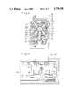
- FIG. 1 is a front view showing a state in which an outer cover of a carrier system is removed;
- FIG. 2 is a plan view thereof
- FIG. 3 is a right side view thereof
- FIG. 4 is a sectional view taken substantially along the line IV--IV of FIG. 1;
- FIG. 5 is a cross-sectional view of a central portion of FIG. 1;
- FIG. 6 is an enlarged horizontal sectional view of a horizontal moving member
- FIG. 7 is an enlarged cross-sectional view of the horizontal moving member
- FIG. 8 is a plan view showing placement of the carrier system
- FIG. 9 is front view showing the placement of the carrier system
- FIG. 10 is a front view of the carrier system equipped with a handling sensor
- FIG. 11 is a right side view showing the upper portion of the carrier system
- FIG. 12 is a cross-sectional view showing the upper portion of the carrier system in another embodiment
- FIG. 13 is a scale-down longitudinal sectional view thereof.
- FIG. 14 is a sectional view taken substantially along the line XIV--XIV of FIG. 12.
- FIG. 1 is a front view of a carrier system for carrying silicon wafers within a clean room;
- FIG. 2 is a plan view thereof; and
- FIG. 3 is a right side view thereof.
- a body of the carrier system in a state where a cover of the body 1 is taken off.
- a bottom plate 2 and an upper plate 3 are linked to each other with the aid of three pieces of guide bars 4.
- a movable plate 5 is disposed in a vertically movable manner and is at the same time guided by the three guide bars 4.
- the movable plate 5 horizontally fluctuates by dint of action of ball screws.
- a cylindrical member 7 is, as illustrated in FIG.
- a screw shaft 8 of the ball screw is rotatably and perpendicularly provided between the bottom plate 2 and the upper plate 3.
- the screw shaft 8 is inserted through the intermediary of the rigid balls into an internal thread 9 formed in a part of the movable plate 5.
- the screw shaft 8 is rotationally driven by a vertical movement motor 10 mounted on the bottom plate 2 through pulleys 11, 12 and through a belt 13, whereby the movable plate 5 moves up and down.
- the cylindrical member 7 perpendicularly provided on the movable plate 5 protrudes upwards from a hole formed in the central portion of the upper plate 3.
- a horizontal moving member 14 is horizontally fixed to the upper end of the cylindrical member 7.
- a gear 16 is attached to the lower end of the cylindrical member 7.
- This gear is, as illustrated in FIG. 3, further linked through a plurality of gearwheels 18 to a turning motor 17 fixed to an under surface of the movable plate 5.
- the cylindrical member 7 and the horizontal moving member 14 are rotated through approximately 360° by dint of the rotation of the turning motor 17.
- a shaft 19 is provided within the cylindrical member 7, and bearings 20, 21 are interposed therebetween.
- the upper end of the shaft 19 enters the horizontal moving member 14, in which position a driving pulley 22 is axially installed.
- the lower end of this driving pulley 22 is fitted in a recessed portion formed in the gear 16, in which position a pinion 23 is axially attached.
- a horizontal moving motor 24 by which the shaft 19 is driven through the pinion 23 is fixed to an under surface of the gear 16 provided at the lower end of the cylindrical member 7. Owing to this arrangement, the driving pulley 22 within the horizontal moving member 14 is rotationally driven. A space formed in the cylindrical member 7 communicates with the inside of the horizontal moving member 14, and a wire for a sensor or the like is distributed therethrough.
- the horizontal moving member 14 is, as shown in FIGS. 6 and 7, so formed as to assume a configuration like a long thin box.
- a slit-like opening is formed in the upper surface of the horizontal moving member 14 in the longitudinal direction thereof.
- Two pieces of guide shafts 26 are disposed at a given spacing in the horizontal moving member 14 in its longitudinal direction.
- a carriage 27 is so supported on the guide shafts 26 as to be horizontally movable.
- Fourteen rollers 30 are axially supported in lateral and vertical directions between the carriage 27, the upper plate 28 and the lower plate 29. Each individual roller 30 impinges upon the guide shaft 26, and the carriage 27 is allowed to travel in the longitudinal direction of the horizontal moving member 14.
- An arm installation member 31 is so provided on the upper plate 28 of the carriage 27 as to project upwards from the opening formed in the upper portion of the horizontal moving member 14.
- a handling plate-like arm 32 is horizontally fitted to the arm installation member 31 which juts out upwards.
- a sensor for detecting the silicon wafers which is illustrated in FIGS. 10, 11 may be so provided that it faces the arm 32 of the arm installation member 31.
- This kind of sensor is composed by two strings of optical fibers 36, a light projecting element and a light receiving element which are fitted to terminals of the optical fibers 36.
- the tips of the two optical fibers 36 are arranged in the direction parallel to the surface of the arm 32, standing on the side of the arm of the arm installation member 31.
- the terminals of the optical fibers 36 are led to the carriage or into the body 1.
- the light is project from the light projecting optical fiber 36 in the direction parallel to the surface of the arm 32. If the silicon wafer remains on the arm 32, the light reflected by the edge thereof enters the light receiving optical fiber 36. The reflected light is detected in the light receiving element 8, thus detecting the fact that the silicon wafer exists on the arm 32.
- the senor is disposed upwards within the arm 32.
- the silicon wafer includes an orientation flat (a notched portion), and if this portion be situated above the sensor, it will become unfeasible to detect the silicon wafer. It is, however, possible to invariably detect the edge of the loaded silicon wafer by placing the sensor in the above-described manner. The wafer on the arm 32 can be detected regardless of the position of the orientation flat of the silicon wafer.
- pulleys 33 are axially supported on both ends of the bottom within the horizontal moving member 14, and a wire 34 coated with synthetic resin is spanned with proper tension between the aforementioned driving pulley 22 disposed at the central portion and the bilaterally disposed pulleys 33.
- the driving pulley 22 is wound with a turn of the wire 34, and similarly a hook 35 projecting downwards from the lower plate 29 of the carriage 27 positioned upwards is wound with a turn of the wire 34.
- the carriage 27 travels within the horizontal moving member 14 by dint of the rotational movement of the wire 34.
- gear, gearwheel and pinion are composed of the synthetic resin in order to prevent creation of the metallic powder which is caused by the metallic abrasion.
- the thus constructed carrier system which is utilised in such a way that the silicon wafers are carried from the shelf type cassette onto the stage of the processing device, and the silicon wafers are made to revert to the predetermined positions of the cassette.
- the arm 32 loaded with the silicon wafer is capable of making the up-and-down motion, turning motion and horizontal to-and-fro motion.
- the carrier system is, as shown in FIGS. 8 and 9, installed in front of a unit of processing device 40, and a plurality of cassettes 41 each having multistage shelf are so arranged as to stand vis-a-vis with the processing device 40. With this arrangement, it is feasible to effectively utilise the space formed within the clean room.
- the arm 32 is placed in such a position as shown in FIGS. 8, 9, and when taking the silicon wafers out of the upper end of the cassette 41 disposed just behind the arm, the cylindrical member 7 and the horizontal moving member 14 are made to rotate through approximately 180° by driving the turning motor 17. Then the arm 32 is made to face the cassette 41, and the same instant the vertical movement motor 10 is actuated, whereby the movable plate 5, the cylindrical member 7 and the horizontal moving member 14 are raised up to a desired level of the shelf. In the wake of this step, a horizontal movement motor 24 is actuated, and the carriage 27 moves on the horizontal moving member 14 towards the cassette 41 by dint of the rotational movement of the driving pulley 22 and the wire 34, whereby the arm 32 is inserted beneath the desired shelf.
- the arm 32 (the entire horizontal moving member) is a little bit raised, and the silicon wafer is loaded on the arm 32.
- the horizontal movement motor 24 resumes its operation, and then the carriage 27--the arm 32--reverts to the central portion while being loaded with the wafer.
- the arm 32 returns to the initial position opposite to the stage of the processing device 40.
- the horizontal movement motor 24 is operated once again, whereby the arm moves forwards.
- the vertical movement motor 10 is slightly actuated in order to lower the arm 32 a little bit while the wafer is brought close to the stage. Subsequently, the wafer is placed on the stage of the processing device 40. Thereafter, the carriage 27 and the arm 32 return to their initial positions.
- the arm 32 of the carrier system is operated in the reversed order of the above-described steps.
- the arm 32 advances onto the stage to raise the wafer and carry this wafer up to the very shelf of the cassette 41 from which the the wafer is taken, thus returning the wafer to the shelf.
- Such operations are repeated with respect to the individual wafers which are put on the shelves of each cassette.
- the processes indispensable for the transfer of the silicon wafers are thus executed.
- the arm for carrying the electronic parts while being loaded with them is capable of making the horizontal, up-and-down and turning motions, it is possible to carry the electronic parts in three dimensions.
- a conventionally required lift/lowering device of the cassette which accomodates the electronic parts becomes unnecessary.
- the cassette can be installed in the arbitrary position within the clean room, the installation space inclusive of the cassette or the like can be diminished.
- the operations of the foregoing carrier system can manually be performed by the use of control panel equipped with switches or may be done under full-automatic program control with the help of a sequence controller which employs a microcomputer.
- the controller is invested with a teaching function so as to store coordinates of the respective shelves of each individual cassette. With this arrangement, the usability is expanded to such an extent that the position of the cassette and the level of the shelf are freely determined.
- the arm 32 carries the silicon wafer by placing it thereon.
- a still safer transport is possible due to such a structure that adsoptive holes through which the air is sucked thereinto are formed in the upper surface of the arm 32.
- FIGS. 12 to 14 in combination show another embodiment of the carriage.
- This carriage is arranged to travel on a single rail 52; and within the horizontal moving member 51 the rail 52 is laid in the longitudinal direction thereof.
- the rail 52 is constituted by fixing a rod member 52b which assumes circularity in section to a tabular member 52a.
- the carriage 53 is disposed astride the rail 52.
- the carriage 53 is formed with recessed portions (a cylindrical recessed portion 58 and a tabular recessed portion communicating with the former recessed portion 58) through which the rail 52 passes.
- wheel insertion grooves 60 inclined at an angle of approximately 45° to the cylindrical recessed portion 58 are formed in the carriage 53. To be specific, these grooves 60 are, as illustrated in a sectional view of FIG.
- a groove 61 used for insertion of a spindle of every wheel is so formed as to intersect each of eight stripes of the grooves 60.
- Wheels 54 composed by fitting spindles 54a into inner rings of antifriction bearings are respectively inserted in the eight grooves 60 which are formed in front and in rear of the carriage 53. From the front and rear sides of the carriage 53, fixing members are fitted in the grooves 61 in which the spindles 54a are inserted, and front and back plates are fixed in front and in rear of the carriage 53, thus installing the wheels in the predetermined positions.
- An opening is formed in the upper portion of the horizontal moving member 51 in the longitudinal direction thereof.
- An installation member 56 is fixed to the upper portion of the carriage 53 in such a way that this installation member 56 protrudes upwards from the aforementioned opening; and an arm 57 is horizontally provided in front of the installation member 56.
- a driving wire 62 for driving the carriage 53 is spanned between pulleys 63, 64 at the bottom of the horizontal moving member 51.
- a driving pulley 65 provided at the center in the horizontal moving member 51 is wound with one end of a driving wire 62, while at the same time the other end of the wire 62 is fixedly hung on a tension adjusting member 66 attached to the side portion of the carriage 53.
- the horizontal moving member 51 is fixed to a cylindrical member 67 which is linked to an unillustrated vertical movement mechanism and to a turning mechanism.
- a rotary driving shaft (not illustrated) perpendicularly passes through the cylindrical member 67. The tip of the rotary driving shaft protrudes and is further connected to the driving pulley 65.
- the thus constructed carrier system behaves such that: the driving pulley 65 rotates by dint of the unillustrated rotary driving shaft, thereby rotating the driving wire 62 wound thereon; the carriage 53 travels on the rail 52 laid in the horizontal moving member 51 with the aid of the driving wire 62; and the arm 57 is loaded with the silicon wafer so as to carry it to a predetermined position.
- eight pieces of the wheels 54 and four pieces wheels 55 engage with the rail 52 in a highly accurate manner with no play, which enables the carriage 53 to stably travel thereon without rattling.
- the wheels 54, 55 are composed by the antifriction bearings, and internal rigid balls are hermetically sealed with almost no gap.
Landscapes
- Engineering & Computer Science (AREA)
- Robotics (AREA)
- Physics & Mathematics (AREA)
- Condensed Matter Physics & Semiconductors (AREA)
- General Physics & Mathematics (AREA)
- Manufacturing & Machinery (AREA)
- Computer Hardware Design (AREA)
- Microelectronics & Electronic Packaging (AREA)
- Power Engineering (AREA)
- Container, Conveyance, Adherence, Positioning, Of Wafer (AREA)
Abstract
Description
Claims (3)
Priority Applications (1)
| Application Number | Priority Date | Filing Date | Title |
|---|---|---|---|
| US07/039,862 US4735548A (en) | 1987-04-20 | 1987-04-20 | Carrier system for clean room |
Applications Claiming Priority (1)
| Application Number | Priority Date | Filing Date | Title |
|---|---|---|---|
| US07/039,862 US4735548A (en) | 1987-04-20 | 1987-04-20 | Carrier system for clean room |
Publications (1)
| Publication Number | Publication Date |
|---|---|
| US4735548A true US4735548A (en) | 1988-04-05 |
Family
ID=21907722
Family Applications (1)
| Application Number | Title | Priority Date | Filing Date |
|---|---|---|---|
| US07/039,862 Expired - Lifetime US4735548A (en) | 1987-04-20 | 1987-04-20 | Carrier system for clean room |
Country Status (1)
| Country | Link |
|---|---|
| US (1) | US4735548A (en) |
Cited By (12)
| Publication number | Priority date | Publication date | Assignee | Title |
|---|---|---|---|---|
| US4952299A (en) * | 1988-10-31 | 1990-08-28 | Eaton Corporation | Wafer handling apparatus |
| US5135349A (en) * | 1990-05-17 | 1992-08-04 | Cybeq Systems, Inc. | Robotic handling system |
| US5407314A (en) * | 1992-10-01 | 1995-04-18 | Leybold Aktiengesellschaft | Apparatus for synchronizing loading and unloading of substrates with turntable movement in a coating chamber |
| US5810549A (en) * | 1996-04-17 | 1998-09-22 | Applied Materials, Inc. | Independent linear dual-blade robot and method for transferring wafers |
| US5881603A (en) * | 1994-11-02 | 1999-03-16 | Nawaseikiseisakushi Corporation | Transfer unit |
| US6116841A (en) * | 1997-07-30 | 2000-09-12 | Tokyo Electron Limited | Substrate transferring apparatus and substrate processing apparatus using the same |
| US6175159B1 (en) | 1997-07-16 | 2001-01-16 | Oki Electric Industry Co., Ltd. | Semiconductor package |
| US20020146304A1 (en) * | 2001-03-02 | 2002-10-10 | Yoshihiro Yamashita | Vacuum apparatus and transfer apparatus |
| US6661099B2 (en) | 1997-07-16 | 2003-12-09 | Oki Electric Industry Co., Ltd. | Semiconductor device, semiconductor package for use therein, and manufacturing method thereof |
| US20050143236A1 (en) * | 2003-12-25 | 2005-06-30 | Shunsuke Nakazawa | Tool changer of machine tool |
| CN103928376A (en) * | 2013-01-10 | 2014-07-16 | 苏州工业园区高登威科技有限公司 | Resin feeding system |
| US11387128B2 (en) * | 2018-03-31 | 2022-07-12 | Hirata Corporation | Chamber structure |
Citations (5)
| Publication number | Priority date | Publication date | Assignee | Title |
|---|---|---|---|---|
| US3825245A (en) * | 1972-04-24 | 1974-07-23 | Kearney & Trecker Corp | Workpiece changer mechanism for a machine tool |
| US4366423A (en) * | 1978-01-31 | 1982-12-28 | Fujitsu Fanuc Limited | Industrial robot system |
| US4507044A (en) * | 1981-12-08 | 1985-03-26 | Zymark Corporation | Robot and control system |
| US4566346A (en) * | 1981-03-10 | 1986-01-28 | Petiteau Maurice R | Automated tool manipulating structure with X-Y movement including a belt and pulley drive arrangement |
| US4566847A (en) * | 1982-03-01 | 1986-01-28 | Kabushiki Kaisha Daini Seikosha | Industrial robot |
-
1987
- 1987-04-20 US US07/039,862 patent/US4735548A/en not_active Expired - Lifetime
Patent Citations (5)
| Publication number | Priority date | Publication date | Assignee | Title |
|---|---|---|---|---|
| US3825245A (en) * | 1972-04-24 | 1974-07-23 | Kearney & Trecker Corp | Workpiece changer mechanism for a machine tool |
| US4366423A (en) * | 1978-01-31 | 1982-12-28 | Fujitsu Fanuc Limited | Industrial robot system |
| US4566346A (en) * | 1981-03-10 | 1986-01-28 | Petiteau Maurice R | Automated tool manipulating structure with X-Y movement including a belt and pulley drive arrangement |
| US4507044A (en) * | 1981-12-08 | 1985-03-26 | Zymark Corporation | Robot and control system |
| US4566847A (en) * | 1982-03-01 | 1986-01-28 | Kabushiki Kaisha Daini Seikosha | Industrial robot |
Cited By (22)
| Publication number | Priority date | Publication date | Assignee | Title |
|---|---|---|---|---|
| US4952299A (en) * | 1988-10-31 | 1990-08-28 | Eaton Corporation | Wafer handling apparatus |
| US5135349A (en) * | 1990-05-17 | 1992-08-04 | Cybeq Systems, Inc. | Robotic handling system |
| US5407314A (en) * | 1992-10-01 | 1995-04-18 | Leybold Aktiengesellschaft | Apparatus for synchronizing loading and unloading of substrates with turntable movement in a coating chamber |
| US5881603A (en) * | 1994-11-02 | 1999-03-16 | Nawaseikiseisakushi Corporation | Transfer unit |
| US5810549A (en) * | 1996-04-17 | 1998-09-22 | Applied Materials, Inc. | Independent linear dual-blade robot and method for transferring wafers |
| US6175159B1 (en) | 1997-07-16 | 2001-01-16 | Oki Electric Industry Co., Ltd. | Semiconductor package |
| US7129587B2 (en) | 1997-07-16 | 2006-10-31 | Oki Electric Industry Co., Ltd. | Semiconductor device, semiconductor package for use therein, and manufacturing method thereof |
| US8018076B2 (en) | 1997-07-16 | 2011-09-13 | Oki Semiconductor Co., Ltd. | Semiconductor device, semiconductor package for use therein, and manufacturing method thereof |
| US6661099B2 (en) | 1997-07-16 | 2003-12-09 | Oki Electric Industry Co., Ltd. | Semiconductor device, semiconductor package for use therein, and manufacturing method thereof |
| US20040082102A1 (en) * | 1997-07-16 | 2004-04-29 | Takaaki Sasaki | Semiconductor device, semiconductor package for use therein, and manufacturing method thereof |
| US7663251B2 (en) | 1997-07-16 | 2010-02-16 | Oki Semiconductor Co., Ltd. | Semiconductor device, semiconductor package for use therein, and manufacturing method thereof |
| US6890796B1 (en) | 1997-07-16 | 2005-05-10 | Oki Electric Industry Co., Ltd. | Method of manufacturing a semiconductor package having semiconductor decice mounted thereon and elongate opening through which electodes and patterns are connected |
| US20080230924A1 (en) * | 1997-07-16 | 2008-09-25 | Oki Electric Industry Co., Ltd. | Semiconductor device, semiconductor package for use therein, and manufacturing method thereof |
| US7365439B2 (en) | 1997-07-16 | 2008-04-29 | Oki Electric Industry Co., Ltd. | Semiconductor device, semiconductor package for use therein, and manufacturing method thereof |
| US6116841A (en) * | 1997-07-30 | 2000-09-12 | Tokyo Electron Limited | Substrate transferring apparatus and substrate processing apparatus using the same |
| US6869262B2 (en) * | 2001-03-02 | 2005-03-22 | Seiko Instruments Inc. | Vacuum apparatus and transfer apparatus |
| US20020146304A1 (en) * | 2001-03-02 | 2002-10-10 | Yoshihiro Yamashita | Vacuum apparatus and transfer apparatus |
| US7108647B2 (en) * | 2003-12-25 | 2006-09-19 | Mori Seiki Co., Ltd. | Tool changer of machine tool |
| US20050143236A1 (en) * | 2003-12-25 | 2005-06-30 | Shunsuke Nakazawa | Tool changer of machine tool |
| CN103928376A (en) * | 2013-01-10 | 2014-07-16 | 苏州工业园区高登威科技有限公司 | Resin feeding system |
| CN103928376B (en) * | 2013-01-10 | 2017-02-08 | 苏州高登威科技股份有限公司 | Resin feeding system |
| US11387128B2 (en) * | 2018-03-31 | 2022-07-12 | Hirata Corporation | Chamber structure |
Similar Documents
| Publication | Publication Date | Title |
|---|---|---|
| US4735548A (en) | Carrier system for clean room | |
| US4778331A (en) | Carrier system for silicon wafer | |
| KR100555620B1 (en) | Board Transport System and Transport Method | |
| KR0155172B1 (en) | Plate-like member conveying apparatus | |
| CN108656123B (en) | Industrial robot | |
| US5365672A (en) | Positioning apparatus for a semiconductor wafer | |
| JPS6329410B2 (en) | ||
| US4570058A (en) | Method and apparatus for automatically handling and identifying semiconductor wafers | |
| JPH1079415A (en) | Apparatus for aligning notch and jig for adjusting the same | |
| KR100273837B1 (en) | A providing device for wafer ring | |
| US6820508B2 (en) | Apparatus for rotating a sample | |
| JP2758558B2 (en) | Wafer handling equipment | |
| US6527101B1 (en) | Attitude changing device for electronic chips | |
| WO1987007078A1 (en) | Article transfer apparatus | |
| JP3578593B2 (en) | Substrate alignment device | |
| KR20150080749A (en) | Lifting apparatus and apparatus for transferring substrate comprising the same | |
| JPH0426138A (en) | Conveyor for platelike element | |
| KR101098230B1 (en) | Apparatus for manufacturing the substrate | |
| KR100916538B1 (en) | Multi Sorter Wafer Handling System | |
| JPS63185704A (en) | Handling device for conveyance | |
| KR100758691B1 (en) | Wafer Alignment System and Alignment Method | |
| JP2002319559A (en) | Grinding device | |
| KR200317190Y1 (en) | Balance maintaing device of up/down carriage for stocker | |
| KR102750486B1 (en) | Glass substrate inversion unit and glass substrate inspection apparatus having same | |
| JP3022872B1 (en) | Rubbing apparatus and rubbing method for liquid crystal element |
Legal Events
| Date | Code | Title | Description |
|---|---|---|---|
| AS | Assignment |
Owner name: MECS CORPORATION, 35, OOHIRAURA, HIGASHI-ITSUSHIRO Free format text: ASSIGNMENT OF ASSIGNORS INTEREST.;ASSIGNORS:KIMATA, KAZUO;ISHIKAWA, SUSUMU;REEL/FRAME:004694/0198 Effective date: 19870410 |
|
| STCF | Information on status: patent grant |
Free format text: PATENTED CASE |
|
| FPAY | Fee payment |
Year of fee payment: 4 |
|
| FPAY | Fee payment |
Year of fee payment: 8 |
|
| FPAY | Fee payment |
Year of fee payment: 12 |
|
| AS | Assignment |
Owner name: ASYST JAPAN INC., JAPAN Free format text: CHANGE OF NAME;ASSIGNOR:MECS CORPORATION;REEL/FRAME:012036/0703 Effective date: 20001011 |
|
| AS | Assignment |
Owner name: BANK OF AMERICA, N.A., AS ADMINISTRATIVE AGENT,WAS Free format text: SECURITY AGREEMENT;ASSIGNORS:ASYST TECHNOLOGIES, INC.;ASYST JAPAN, INC.;REEL/FRAME:018303/0969 Effective date: 20060713 Owner name: BANK OF AMERICA, N.A., AS ADMINISTRATIVE AGENT, WA Free format text: SECURITY AGREEMENT;ASSIGNORS:ASYST TECHNOLOGIES, INC.;ASYST JAPAN, INC.;REEL/FRAME:018303/0969 Effective date: 20060713 |
|
| AS | Assignment |
Owner name: KEYBANK NATIONAL ASSOCIATION, AS ADMINISTRATIVE AG Free format text: SECURITY AGREEMENT;ASSIGNOR:ASYST JAPAN, INC.;REEL/FRAME:019699/0256 Effective date: 20070727 |
|
| AS | Assignment |
Owner name: ASYST TECHNOLOGIES, INC., CALIFORNIA Free format text: RELEASE BY SECURED PARTY;ASSIGNOR:BANK OF AMERICA, N.A., AS ADMINISTRATIVE AGENT;REEL/FRAME:019733/0967 Effective date: 20070727 Owner name: ASYST JAPAN, INC., JAPAN Free format text: RELEASE BY SECURED PARTY;ASSIGNOR:BANK OF AMERICA, N.A., AS ADMINISTRATIVE AGENT;REEL/FRAME:019733/0967 Effective date: 20070727 Owner name: ASYST TECHNOLOGIES, INC.,CALIFORNIA Free format text: RELEASE BY SECURED PARTY;ASSIGNOR:BANK OF AMERICA, N.A., AS ADMINISTRATIVE AGENT;REEL/FRAME:019733/0967 Effective date: 20070727 Owner name: ASYST JAPAN, INC.,JAPAN Free format text: RELEASE BY SECURED PARTY;ASSIGNOR:BANK OF AMERICA, N.A., AS ADMINISTRATIVE AGENT;REEL/FRAME:019733/0967 Effective date: 20070727 |