US4687386A - Apparatus for performing machining operations in poorly accessible locations - Google Patents
Apparatus for performing machining operations in poorly accessible locations Download PDFInfo
- Publication number
- US4687386A US4687386A US06/734,733 US73473385A US4687386A US 4687386 A US4687386 A US 4687386A US 73473385 A US73473385 A US 73473385A US 4687386 A US4687386 A US 4687386A
- Authority
- US
- United States
- Prior art keywords
- telescopic guide
- housing
- drive shaft
- fastening head
- guide
- Prior art date
- Legal status (The legal status is an assumption and is not a legal conclusion. Google has not performed a legal analysis and makes no representation as to the accuracy of the status listed.)
- Expired - Fee Related
Links
Images


Classifications
-
- B—PERFORMING OPERATIONS; TRANSPORTING
- B25—HAND TOOLS; PORTABLE POWER-DRIVEN TOOLS; MANIPULATORS
- B25F—COMBINATION OR MULTI-PURPOSE TOOLS NOT OTHERWISE PROVIDED FOR; DETAILS OR COMPONENTS OF PORTABLE POWER-DRIVEN TOOLS NOT PARTICULARLY RELATED TO THE OPERATIONS PERFORMED AND NOT OTHERWISE PROVIDED FOR
- B25F5/00—Details or components of portable power-driven tools not particularly related to the operations performed and not otherwise provided for
- B25F5/003—Stops for limiting depth in rotary hand tools
-
- B—PERFORMING OPERATIONS; TRANSPORTING
- B23—MACHINE TOOLS; METAL-WORKING NOT OTHERWISE PROVIDED FOR
- B23Q—DETAILS, COMPONENTS, OR ACCESSORIES FOR MACHINE TOOLS, e.g. ARRANGEMENTS FOR COPYING OR CONTROLLING; MACHINE TOOLS IN GENERAL CHARACTERISED BY THE CONSTRUCTION OF PARTICULAR DETAILS OR COMPONENTS; COMBINATIONS OR ASSOCIATIONS OF METAL-WORKING MACHINES, NOT DIRECTED TO A PARTICULAR RESULT
- B23Q5/00—Driving or feeding mechanisms; Control arrangements therefor
- B23Q5/02—Driving main working members
- B23Q5/04—Driving main working members rotary shafts, e.g. working-spindles
- B23Q5/043—Accessories for spindle drives
- B23Q5/045—Angle drives
-
- Y—GENERAL TAGGING OF NEW TECHNOLOGICAL DEVELOPMENTS; GENERAL TAGGING OF CROSS-SECTIONAL TECHNOLOGIES SPANNING OVER SEVERAL SECTIONS OF THE IPC; TECHNICAL SUBJECTS COVERED BY FORMER USPC CROSS-REFERENCE ART COLLECTIONS [XRACs] AND DIGESTS
- Y10—TECHNICAL SUBJECTS COVERED BY FORMER USPC
- Y10T—TECHNICAL SUBJECTS COVERED BY FORMER US CLASSIFICATION
- Y10T408/00—Cutting by use of rotating axially moving tool
- Y10T408/55—Cutting by use of rotating axially moving tool with work-engaging structure other than Tool or tool-support
- Y10T408/561—Having tool-opposing, work-engaging surface
- Y10T408/5612—Tool having shiftable tool-axis
-
- Y—GENERAL TAGGING OF NEW TECHNOLOGICAL DEVELOPMENTS; GENERAL TAGGING OF CROSS-SECTIONAL TECHNOLOGIES SPANNING OVER SEVERAL SECTIONS OF THE IPC; TECHNICAL SUBJECTS COVERED BY FORMER USPC CROSS-REFERENCE ART COLLECTIONS [XRACs] AND DIGESTS
- Y10—TECHNICAL SUBJECTS COVERED BY FORMER USPC
- Y10T—TECHNICAL SUBJECTS COVERED BY FORMER US CLASSIFICATION
- Y10T408/00—Cutting by use of rotating axially moving tool
- Y10T408/55—Cutting by use of rotating axially moving tool with work-engaging structure other than Tool or tool-support
- Y10T408/561—Having tool-opposing, work-engaging surface
- Y10T408/5623—Having tool-opposing, work-engaging surface with presser foot
-
- Y—GENERAL TAGGING OF NEW TECHNOLOGICAL DEVELOPMENTS; GENERAL TAGGING OF CROSS-SECTIONAL TECHNOLOGIES SPANNING OVER SEVERAL SECTIONS OF THE IPC; TECHNICAL SUBJECTS COVERED BY FORMER USPC CROSS-REFERENCE ART COLLECTIONS [XRACs] AND DIGESTS
- Y10—TECHNICAL SUBJECTS COVERED BY FORMER USPC
- Y10T—TECHNICAL SUBJECTS COVERED BY FORMER US CLASSIFICATION
- Y10T408/00—Cutting by use of rotating axially moving tool
- Y10T408/55—Cutting by use of rotating axially moving tool with work-engaging structure other than Tool or tool-support
- Y10T408/564—Movable relative to Tool along tool-axis
- Y10T408/5653—Movable relative to Tool along tool-axis with means to bias Tool away from work
Definitions
- the present invention relates to an apparatus for performing machining operations in niches or crevices located behind, above or below obstacles, that is, in locations that are inaccessible for standard machining tools.
- Conventional machining tools such as drilling machines, are very long in the lengthwise dimension of the drill when it is fastened in place, and they do not enable drilling a hole, for instance, in such locations as those described above.
- Another object of the present invention is to provide an apparatus of the type described which is light-weight and easily transported, for example by hand from one machining location to another.
- Yet another object of the invention to provide a simple bore or a threaded bore to accurate dimensions even in locations that are impossible to see with the eye.
- the apparatus for performing machining operations in poorly accessible locations includes a fastening head for receiving the tool, with the head being connected via a bevel gear drive with a drive shaft guided in a longitudinal housing.
- the end of the drive shaft can be clamped into the fastening head of a drive machine, and a telescopic guide is provided on the longitudinal housing for the drive shaft.
- the telescopic guide is at a right angle to the drive shaft and is displaceable in the longitudinal direction of the housing, i.e. along the axis of the housing.
- this apparatus In the lengthwise direction, for instance along the length of a drill fastened into place, this apparatus has only a short length, so that it can be used in extremely tight and poorly accessible locations, such as behind, above or below obstacles.
- a conventional drive machine for instance a drilling machine, can be connected to the drive shaft, so that the invention represents a piece of simply structured supplementary equipment for a drilling machine.
- grinding or polishing equipment can also be fastened into the fastening head, so that various operations can be performed in the poorly accessible locations.
- the telescopic guide is preferably displaceable counter to the pressure of a spring. This provision makes it possible to guide the drill fastened into the fastening head in a precisely proportioned and tilt-free manner.
- the telescopic guide which has a stop shoulder at its outer end, is displaceable in the longitudinal direction of the housing and can be fixed thereto via an adjusting screw.
- the longitudinal housing is provided with a scale which indicates the distance of the telescopic guide from the central axis of the fastening head. This distance can accordingly be set precisely, so that a bore can be produced to accurate dimensions even in locations the operator of the tool cannot actually see with his eye. So that this distance can be adjusted accurately, a micrometer screw is provided for fine adjustment.
- the apparatus may be held using a handle, which is guided along the longitudinal housing.
- the handle can be locked in any arbitrary position.
- the longitudinal housing has a simple structure, in two parts longitudinally, and is correspondingly inexpensive to manufacture.
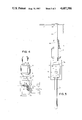
- FIG. 1 is a front view of the apparatus according to the invention.
- FIG. 2 is a front view of the telescopic guide, partically cut away, on a larger scale
- FIG. 3 is a side view of the telescopic guide shown in FIG. 2;
- FIG. 4 is a front view of the fastening head of the apparatus with the housing cut away, in order to show the bevel gear drive;
- FIG. 5 is a side view of the apparatus according to FIG. 1.
- the apparatus shown in FIG. 1 represents a portable specialized tool, one not bound to an assigned location, which can be connected to a conventional drive machine, such as a drilling machine available in commerce, so as to produce bores in inaccessible locations and also to perform other machining operations for which rotation is a suitable type of drive.
- a conventional drive machine such as a drilling machine available in commerce
- a conventional fastening head 6 bears a drill 10 by way of example in the present case, by means of which a bore is to be produced in a poorly accessible locations, such as a niche in a article 1.
- the fastening head 6 is retained on the end of a shaft stub 11, which is guided inside the wall of a housing 12 by means of a bearing 13.
- a bevel gear 14 is held in place, meshing with a further bevel gear 15, which is secured on the end of a drive shaft 9 positioned at a right angle to the shaft stub 11.
- the drive shaft 9 is disposed inside a longitudinal housing 4 and at the end protrudes outward beyond this housing, so that the projecting portion of the drive shaft 9 can be received by the fastening head (not shown) of the drive machine, for instance a hand drilling machine.
- FIG. 3 shows an end view of the longitudinal housing 4.
- the longitudinal housing 4 On its underside, the longitudinal housing 4 has a dovetail groove 16 for slidably receiving a handle 8 (not shown here but which is visible in FIGS. 1 and 5) which is displaceable and adjustable in the longitudinal direction of the housing 4.
- the longitudinal housing 4 is furthermore provided with a scale 17, the purpose of which will be descibed later.
- the longitudinal housing 4 has further grooves 18 on its front and back for slidably receiving a slide 3, which can be fixed in terms of its sliding movement relative to the longitudinal housing 4 by means of an adjusting screw 5.
- the slide 3 is provided on its top with a further groove, upon which a micrometer slide 3a is mounted.
- the micrometer slide 3a can be adjusted relative to the slide 3 via a micrometer screw 7.
- a telescopic guide 2 is secured to the micrometer slide 3a and is oriented at right angles to the longitudinal axis of the housing 4.
- the telescopic guide 2 comprises two parts 2a and 2b that can be telescoped one inside the other; as shown particularly in FIG. 2, the telescopic part 2b is subject to an outwardly exerted pressure of the spring 19.
- the telescopic part 2b On its outer end, the telescopic part 2b has a stop or shoulder 2c, which is held via a screw 20 and is supported on the workpiece or structural part that is to be machined.
- a cover plate 4a that covers the grooves 16 and 18 is retained via screws, in order to prevent unintentional slipping of the handle 8 or slide 3.
- the slide 3 is displaced along the longitudinal housing 4, using the scale 17, which indicates the distance from the central axis of the fastening head 6. Fine adjustment can be attained using the micrometer screw 7, by means of which the micrometer slide 3a is adjusted relative to the slide 3.
- the shoulder 2c is positioned at the edge of the niche, and with the motor actuated the apparatus is pressed in a direction toward the surface of the niche or wall, into which the bore is to be drilled (indicated by the arrow A), whereupon the bore is produced at the intended location with high precision.
- the telescopic part 2b is displaced into the telescopic part 2a counter to the pressure of the spring 19. Because of the telescopic guidance, tilting of the drill 10, about the direction in which the apparatus is pressed, is reliably prevented.
- the apparatus can be put to use for rough operations of the most diverse kind. As with conventional hand drilling machines, compass saws, steel brushes, grinding wheels and the like can be clamped into the fastening head 6.
- the part 2b of the telescopic guide 2 can also be provided with a scale, which indicates the depth to which a drill 10 fastened in the fastening head 6 is inserted.
Landscapes
- Engineering & Computer Science (AREA)
- Mechanical Engineering (AREA)
- Drilling And Boring (AREA)
- Processing Of Stones Or Stones Resemblance Materials (AREA)
Abstract
An apparatus for performing machining operations in poorly accessible locations includes a fastening head, which is held at one end of a shaft stub, while the other end is in engagement via a bevel gear drive with a drive shaft which is retained in a longitudinal housing. A longitudinally displaceable telescopic guide is provided on the longitudinal housing at right angles thereto. The telescopic guide is compressible counter to the pressure of a spring. A micrometer screw is provided for fine adjustment of the distance between the fastening head and the telescopic guide.
Description
This application is a continuation-in-part of U.S. Ser. No. 440,438 filed Nov. 9, 1982 now abandoned.
The present invention relates to an apparatus for performing machining operations in niches or crevices located behind, above or below obstacles, that is, in locations that are inaccessible for standard machining tools.
Conventional machining tools, such as drilling machines, are very long in the lengthwise dimension of the drill when it is fastened in place, and they do not enable drilling a hole, for instance, in such locations as those described above.
It is accordingly the object of the present invention to provide an apparatus which makes it possible to perform various machining operations, such as drilling, grinding, and polishing, in such inaccessible locations, which cannot be reached using standard equipment.
Another object of the present invention is to provide an apparatus of the type described which is light-weight and easily transported, for example by hand from one machining location to another.
Yet another object of the invention to provide a simple bore or a threaded bore to accurate dimensions even in locations that are impossible to see with the eye.
Furthermore, according to the invention it should be possible to produce a bore in a poorly accessible location without tilting of the drilling tool.
This object is attained in accordance with the invention by means of the characteristics of the main claim, and preferred forms of embodiment of the invention are attained by means of the characteristics of the dependent claims.
According to the invention, the apparatus for performing machining operations in poorly accessible locations includes a fastening head for receiving the tool, with the head being connected via a bevel gear drive with a drive shaft guided in a longitudinal housing. The end of the drive shaft can be clamped into the fastening head of a drive machine, and a telescopic guide is provided on the longitudinal housing for the drive shaft. The telescopic guide is at a right angle to the drive shaft and is displaceable in the longitudinal direction of the housing, i.e. along the axis of the housing.
In the lengthwise direction, for instance along the length of a drill fastened into place, this apparatus has only a short length, so that it can be used in extremely tight and poorly accessible locations, such as behind, above or below obstacles. A conventional drive machine, for instance a drilling machine, can be connected to the drive shaft, so that the invention represents a piece of simply structured supplementary equipment for a drilling machine. Besides the drill, grinding or polishing equipment can also be fastened into the fastening head, so that various operations can be performed in the poorly accessible locations.
The telescopic guide is preferably displaceable counter to the pressure of a spring. This provision makes it possible to guide the drill fastened into the fastening head in a precisely proportioned and tilt-free manner. The telescopic guide, which has a stop shoulder at its outer end, is displaceable in the longitudinal direction of the housing and can be fixed thereto via an adjusting screw. The longitudinal housing is provided with a scale which indicates the distance of the telescopic guide from the central axis of the fastening head. This distance can accordingly be set precisely, so that a bore can be produced to accurate dimensions even in locations the operator of the tool cannot actually see with his eye. So that this distance can be adjusted accurately, a micrometer screw is provided for fine adjustment.
The apparatus may be held using a handle, which is guided along the longitudinal housing. The handle can be locked in any arbitrary position. The longitudinal housing has a simple structure, in two parts longitudinally, and is correspondingly inexpensive to manufacture.
Further advantages, details and characteristics of the invention will become apparent from the ensuing description of a preferred embodiment of the apparatus according to the invention, taken in conjunction with the accompanying drawings in which:
FIG. 1 is a front view of the apparatus according to the invention;
FIG. 2 is a front view of the telescopic guide, partically cut away, on a larger scale;
FIG. 3 is a side view of the telescopic guide shown in FIG. 2;
FIG. 4 is a front view of the fastening head of the apparatus with the housing cut away, in order to show the bevel gear drive; and
FIG. 5 is a side view of the apparatus according to FIG. 1.
The apparatus shown in FIG. 1 represents a portable specialized tool, one not bound to an assigned location, which can be connected to a conventional drive machine, such as a drilling machine available in commerce, so as to produce bores in inaccessible locations and also to perform other machining operations for which rotation is a suitable type of drive.
A conventional fastening head 6 bears a drill 10 by way of example in the present case, by means of which a bore is to be produced in a poorly accessible locations, such as a niche in a article 1. As shown in FIG. 4, the fastening head 6 is retained on the end of a shaft stub 11, which is guided inside the wall of a housing 12 by means of a bearing 13. On the end of the shaft stub 11 opposite the fastening head 6, a bevel gear 14 is held in place, meshing with a further bevel gear 15, which is secured on the end of a drive shaft 9 positioned at a right angle to the shaft stub 11.
The drive shaft 9 is disposed inside a longitudinal housing 4 and at the end protrudes outward beyond this housing, so that the projecting portion of the drive shaft 9 can be received by the fastening head (not shown) of the drive machine, for instance a hand drilling machine.
FIG. 3 shows an end view of the longitudinal housing 4. On its underside, the longitudinal housing 4 has a dovetail groove 16 for slidably receiving a handle 8 (not shown here but which is visible in FIGS. 1 and 5) which is displaceable and adjustable in the longitudinal direction of the housing 4.
The longitudinal housing 4 is furthermore provided with a scale 17, the purpose of which will be descibed later.
As clearly shown in FIG. 3, the longitudinal housing 4 has further grooves 18 on its front and back for slidably receiving a slide 3, which can be fixed in terms of its sliding movement relative to the longitudinal housing 4 by means of an adjusting screw 5. The slide 3 is provided on its top with a further groove, upon which a micrometer slide 3a is mounted. The micrometer slide 3a can be adjusted relative to the slide 3 via a micrometer screw 7.
A telescopic guide 2 is secured to the micrometer slide 3a and is oriented at right angles to the longitudinal axis of the housing 4. The telescopic guide 2 comprises two parts 2a and 2b that can be telescoped one inside the other; as shown particularly in FIG. 2, the telescopic part 2b is subject to an outwardly exerted pressure of the spring 19. On its outer end, the telescopic part 2b has a stop or shoulder 2c, which is held via a screw 20 and is supported on the workpiece or structural part that is to be machined.
On the outer end of the longitudinal housing 4, a cover plate 4a that covers the grooves 16 and 18 is retained via screws, in order to prevent unintentional slipping of the handle 8 or slide 3.
An apparatus is thereby provided, by means of which bores can be drilled or other machining operations can be performed in poorly accessible locations, as will be explained in further detail below.
If the bore is to be made in the top, bottom or side of a niche in a wall, for example, spaced apart by a predetermined distance from the edge of the niche, then first the slide 3 is displaced along the longitudinal housing 4, using the scale 17, which indicates the distance from the central axis of the fastening head 6. Fine adjustment can be attained using the micrometer screw 7, by means of which the micrometer slide 3a is adjusted relative to the slide 3.
Now the shoulder 2c is positioned at the edge of the niche, and with the motor actuated the apparatus is pressed in a direction toward the surface of the niche or wall, into which the bore is to be drilled (indicated by the arrow A), whereupon the bore is produced at the intended location with high precision. The telescopic part 2b is displaced into the telescopic part 2a counter to the pressure of the spring 19. Because of the telescopic guidance, tilting of the drill 10, about the direction in which the apparatus is pressed, is reliably prevented.
Once the telescopic guide 2 is removed by withdrawing it from the grooves of the longitudinal housing 4, the apparatus can be put to use for rough operations of the most diverse kind. As with conventional hand drilling machines, compass saws, steel brushes, grinding wheels and the like can be clamped into the fastening head 6.
Finally, the part 2b of the telescopic guide 2 can also be provided with a scale, which indicates the depth to which a drill 10 fastened in the fastening head 6 is inserted.
It should expressly be noted again that the foregoing description addresses merely a preferred exemplary embodiment, and that various alternations and modificationss may be made without departing from the scope of the inventon.
Claims (13)
1. An apparatus for performing machinery operations on a work surface within a niche or crevice constituting a poorly accessible location, comprising
a fastening head for receiving a machining tool for rotation about a first axis;
a drive shaft having a second axis located at a right angle from said first axis, said drive shaft having a distal end which is fastenable to a drive machine;
bevel gear means for rotatably connecting said fastening head to said drive shaft;
a longitudinal housing for said drive shaft extending along the axial length of said drive shaft and providing guiding means therefor;
a spring urged telescopic guide extending from said longitudinal housing at a right angle from said drive shaft, said telescoping guide telescoping in a direction along said first axis, said telescopic guide having a distal end;
means for displaceably mounting said telescopic guide on said housing and for fixedly locating said telescopic guide at a selected location along the length of said housing from said fastening head; and
support means, located at said distal end of said telescopic guide, for abuttingly bracing said apparatus against the work surface to be machined without attachment thereto,
wherein said telescoping of said telescopic guide allows advancement of the apparatus in the direction of said first axis as said work surface is machined by said machining tool.
2. An apparatus according to claim 1 wherein said support means for bracing said apparatus against the work surface to be machined comprises a shoulder affixed to the distal end of said telescoping guide.
3. An apparatus according to claim 1 wherein said means for displaceably mounting said telescopic guide on said housing comprises a dove tail guide.
4. An apparatus according to claim 1 further comprising an exterior scale on said longitudinal housing for accurately determining the distance of said telescopic guide from said fastening head.
5. An apparatus according to claim 1 wherein said means for fixedly locating said telescopic guide at a selected location along the length of said housing from said fastening head comprises an adjusting screw.
6. An apparatus according to claim 1 wherein said means for displaceably mounting said telescopic guide on said housing and for fixably locating said telescopic guide at a selected location along the length of said housing from said fastening head comprises a dove tail guide and an adjusting screw.
7. An apparatus according to claim 1 wherein said means for displaceably mounting said telescopic guide on said housing comprises a slidable mounting block.
8. An apparatus according to claim 7, wherein said telescopic guide is mounted on said slidable mounting block through a fine adjustment means, said fine adjustment means including a micrometer screw for fine adjustment of the distance between said telescopic guide and said fastening head.
9. An apparatus according to claim 1 wherein said telescopic guide comprises a first hollow portion and a second portion which telescopes within said first hollow portion, and distance determining means to indicate the depth into the work surface a machining tool as penetrated, said distance determining means comprising an external side on said second portion.
10. An apparatus according to claim 1 further comprising a handle and means for mounting said handle on said longitudinal housing for displacement along the length thereto.
11. An apparatus according to claim 22 further comprising means for fixing said handle in a selected position along the length of said longitudinal housing.
12. An apparatus according to claim 1 further comprising handle means for manually transporting said apparatus from one location to another.
13. An apparatus for performing machinery operations on a work surface within a niche or crevice constituting a poorly accessible location, comprising
a fastening head for receiving a machining tool for rotation about a first axis;
a drive shaft having a second axis located at a right angle from said first axis, said drive shaft having a distal end which is fastenable to a drive machine;
bevel gear means for rotatably connecting said fastening head to said drive shaft;
a longitudinal housing for said drive shaft extending along the axial length of said drive shaft and providing guiding means therefor;
a telescopic guide extending from said longitudinal housing at a right angle from said drive shaft, said telescopic guide having a distal end;
means for displaceably mounting said telescopic guide on said housing and for fixedly locating said telescopic guide at a selected location along the length of said housing from said fastening head; and
support means, located at said distal end of said telescoping guide, for abuttingly bracing said apparatus against the work surface to be machined without attachment thereto,
wherein said telescopic guide comprises a first hollow portion, a second portion for slidably moving within said hollow first portion, and a compressible spring carried within said first hollow portion and abutting said spring, said spring becoming compressed as said telescopic guide telescopes to become shorter in length.
Applications Claiming Priority (2)
| Application Number | Priority Date | Filing Date | Title |
|---|---|---|---|
| DE31329[U] | 1981-11-11 | ||
| DE8132934 | 1981-11-11 |
Related Parent Applications (1)
| Application Number | Title | Priority Date | Filing Date |
|---|---|---|---|
| US06440438 Continuation-In-Part | 1982-11-09 |
Publications (1)
| Publication Number | Publication Date |
|---|---|
| US4687386A true US4687386A (en) | 1987-08-18 |
Family
ID=6732910
Family Applications (1)
| Application Number | Title | Priority Date | Filing Date |
|---|---|---|---|
| US06/734,733 Expired - Fee Related US4687386A (en) | 1981-11-11 | 1985-05-16 | Apparatus for performing machining operations in poorly accessible locations |
Country Status (2)
| Country | Link |
|---|---|
| US (1) | US4687386A (en) |
| DE (1) | DE8132934U1 (en) |
Cited By (3)
| Publication number | Priority date | Publication date | Assignee | Title |
|---|---|---|---|---|
| CN102179545A (en) * | 2011-05-13 | 2011-09-14 | 镇江中船设备有限公司 | Drilling device |
| CN108262804A (en) * | 2018-01-18 | 2018-07-10 | 浙江工商大学 | A kind of tubing, pipe fitting perforating device for being used to position temperature sensor |
| US20230114743A1 (en) * | 2021-10-07 | 2023-04-13 | Toyota Motor Engineering & Manufacturing North America, Inc. | Offset-angle extension devices for rotating power tools |
Citations (16)
| Publication number | Priority date | Publication date | Assignee | Title |
|---|---|---|---|---|
| US595896A (en) * | 1897-12-21 | Boring-machine | ||
| US639203A (en) * | 1899-07-24 | 1899-12-12 | Hiram Blanchard Woodill | Boring-machine. |
| US704657A (en) * | 1901-09-10 | 1902-07-15 | Stephen Mcclellan | Joist-boring tool. |
| US894228A (en) * | 1905-12-07 | 1908-07-28 | Walter D Price | Boring-machine. |
| US914759A (en) * | 1907-07-02 | 1909-03-09 | Alfred J Signor | Boring appliance. |
| US960097A (en) * | 1908-08-27 | 1910-05-31 | Luther M Keithley | Angle-boring machine. |
| US973136A (en) * | 1909-03-05 | 1910-10-18 | James W Ogle | Boring-machine. |
| US1011098A (en) * | 1909-11-19 | 1911-12-05 | Wilbur H Washburn | Boring-machine. |
| US1343370A (en) * | 1917-12-07 | 1920-06-15 | Sueur Philip Joshua Le | Breast-drill |
| US1517987A (en) * | 1923-03-02 | 1924-12-02 | Henderson Robert Halsey | Floor-joist-boring machine |
| US3060769A (en) * | 1960-08-19 | 1962-10-30 | Merle J Heider | Portable self-drilling device |
| US3679320A (en) * | 1970-10-28 | 1972-07-25 | Zephyr Mfg Co | Portable right angle drill |
| US3741671A (en) * | 1971-01-08 | 1973-06-26 | R Douglass | Drill guide |
| US3781999A (en) * | 1972-04-26 | 1974-01-01 | P Colangelo | Cutting tool setting device |
| US4281949A (en) * | 1979-08-06 | 1981-08-04 | Bugarin Tony L | Combination depth gauge and level for a drill |
| US4403892A (en) * | 1980-11-03 | 1983-09-13 | Kane Patrick J | Apparatus for driving fasteners and other insertable objects into remote structures |
-
1981
- 1981-11-11 DE DE8132934U patent/DE8132934U1/en not_active Expired
-
1985
- 1985-05-16 US US06/734,733 patent/US4687386A/en not_active Expired - Fee Related
Patent Citations (16)
| Publication number | Priority date | Publication date | Assignee | Title |
|---|---|---|---|---|
| US595896A (en) * | 1897-12-21 | Boring-machine | ||
| US639203A (en) * | 1899-07-24 | 1899-12-12 | Hiram Blanchard Woodill | Boring-machine. |
| US704657A (en) * | 1901-09-10 | 1902-07-15 | Stephen Mcclellan | Joist-boring tool. |
| US894228A (en) * | 1905-12-07 | 1908-07-28 | Walter D Price | Boring-machine. |
| US914759A (en) * | 1907-07-02 | 1909-03-09 | Alfred J Signor | Boring appliance. |
| US960097A (en) * | 1908-08-27 | 1910-05-31 | Luther M Keithley | Angle-boring machine. |
| US973136A (en) * | 1909-03-05 | 1910-10-18 | James W Ogle | Boring-machine. |
| US1011098A (en) * | 1909-11-19 | 1911-12-05 | Wilbur H Washburn | Boring-machine. |
| US1343370A (en) * | 1917-12-07 | 1920-06-15 | Sueur Philip Joshua Le | Breast-drill |
| US1517987A (en) * | 1923-03-02 | 1924-12-02 | Henderson Robert Halsey | Floor-joist-boring machine |
| US3060769A (en) * | 1960-08-19 | 1962-10-30 | Merle J Heider | Portable self-drilling device |
| US3679320A (en) * | 1970-10-28 | 1972-07-25 | Zephyr Mfg Co | Portable right angle drill |
| US3741671A (en) * | 1971-01-08 | 1973-06-26 | R Douglass | Drill guide |
| US3781999A (en) * | 1972-04-26 | 1974-01-01 | P Colangelo | Cutting tool setting device |
| US4281949A (en) * | 1979-08-06 | 1981-08-04 | Bugarin Tony L | Combination depth gauge and level for a drill |
| US4403892A (en) * | 1980-11-03 | 1983-09-13 | Kane Patrick J | Apparatus for driving fasteners and other insertable objects into remote structures |
Cited By (5)
| Publication number | Priority date | Publication date | Assignee | Title |
|---|---|---|---|---|
| CN102179545A (en) * | 2011-05-13 | 2011-09-14 | 镇江中船设备有限公司 | Drilling device |
| CN102179545B (en) * | 2011-05-13 | 2013-04-17 | 镇江中船设备有限公司 | Drilling device |
| CN108262804A (en) * | 2018-01-18 | 2018-07-10 | 浙江工商大学 | A kind of tubing, pipe fitting perforating device for being used to position temperature sensor |
| CN108262804B (en) * | 2018-01-18 | 2019-04-30 | 浙江工商大学 | A punching device for pipes and pipe fittings for positioning temperature sensors |
| US20230114743A1 (en) * | 2021-10-07 | 2023-04-13 | Toyota Motor Engineering & Manufacturing North America, Inc. | Offset-angle extension devices for rotating power tools |
Also Published As
| Publication number | Publication date |
|---|---|
| DE8132934U1 (en) | 1982-04-08 |
Similar Documents
| Publication | Publication Date | Title |
|---|---|---|
| US7621206B2 (en) | Multi-function woodworking guide | |
| US4314782A (en) | Tool guide | |
| US6599064B1 (en) | Combined dowel-hole and pocket-hole drilling apparatus | |
| US4256000A (en) | Adjustable workstop | |
| US5465492A (en) | Alignment device for a hand tool | |
| US5004027A (en) | Biscuit joiner | |
| US20030233926A1 (en) | Multi-function woodworking system | |
| US4262891A (en) | Three dimensional positionable workpiece support table | |
| US3531870A (en) | Chain saw measuring device | |
| US4687386A (en) | Apparatus for performing machining operations in poorly accessible locations | |
| US5915808A (en) | Power saw guide kit | |
| US7131898B2 (en) | Adjustable surface positioning guide for a rotary hand-held tool | |
| EP0296711A1 (en) | Portable power tool | |
| US20030233925A1 (en) | Multi-function woodworking adapter | |
| US6450741B1 (en) | Apparatus for deburring, chamferring and beveling workpieces | |
| US4063577A (en) | Wood lathe tool holder | |
| US4926916A (en) | Biscuit joiner | |
| US4815347A (en) | Lathe attachment with axially movable chuck | |
| US2830378A (en) | Center-punching tool | |
| US8261464B2 (en) | Swivel mounting device | |
| US5662441A (en) | Small scale milling machine | |
| US2742801A (en) | Boring machine | |
| US5217336A (en) | Edge finder | |
| US2821874A (en) | Boring bar | |
| US4702131A (en) | Hand driven precision tapping system |
Legal Events
| Date | Code | Title | Description |
|---|---|---|---|
| REMI | Maintenance fee reminder mailed | ||
| LAPS | Lapse for failure to pay maintenance fees | ||
| STCH | Information on status: patent discontinuation |
Free format text: PATENT EXPIRED DUE TO NONPAYMENT OF MAINTENANCE FEES UNDER 37 CFR 1.362 |
|
| FP | Lapsed due to failure to pay maintenance fee |
Effective date: 19910818 |